Final project - The Airable
Welcome to my final project page in which I document my journey in the creation of the Airable. This was updated on a weekly basis during Fab Academy 2021.
Summary
- Hero shots
- Project description
- Fabrics design and production
- Electronics
- Embedded programming
- Bill of Materials
- Weekly progress
- First sketches (week 1)
- Computational Design (week 2)
- Computer-Controlled Cutting (week 3)
- Electronics Production (week 4)
- 3D Scanning and Printing (week 5)
- Electronics Design (week 6)
- Computer-Controlled Machining (week 7)
- Embedded Programming (week 8)
- Mechanical and Machine Design (week 9)
- Input Devices (week 10)
- Molding and Casting (week 11)
- Output Devices (week 12)
- Networking and Communications (week 13)
- Interface and Application Programming (week 14)
- Wildcard Week (week 15)
- Applications and Implications (week 16)
- Invention, IP and Business Models (week 17)
- Next steps
- Downloads
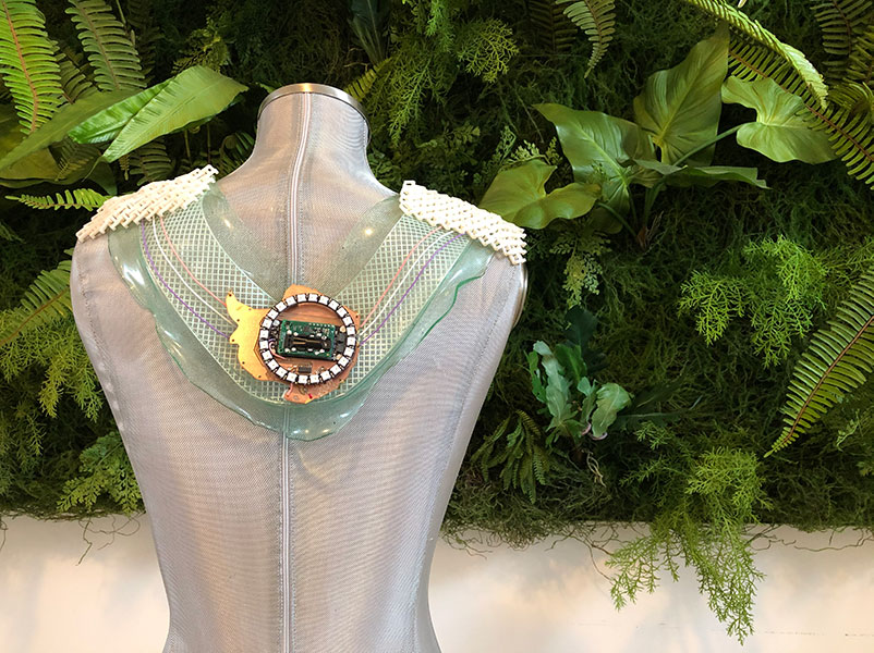
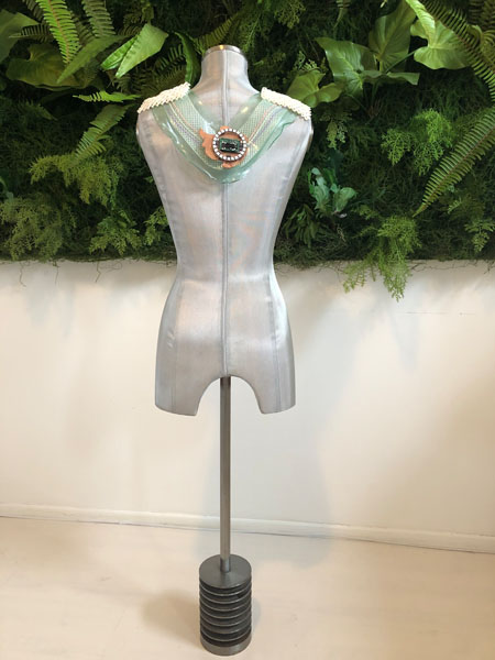
Hero shots
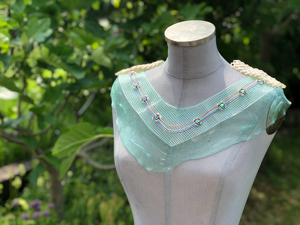
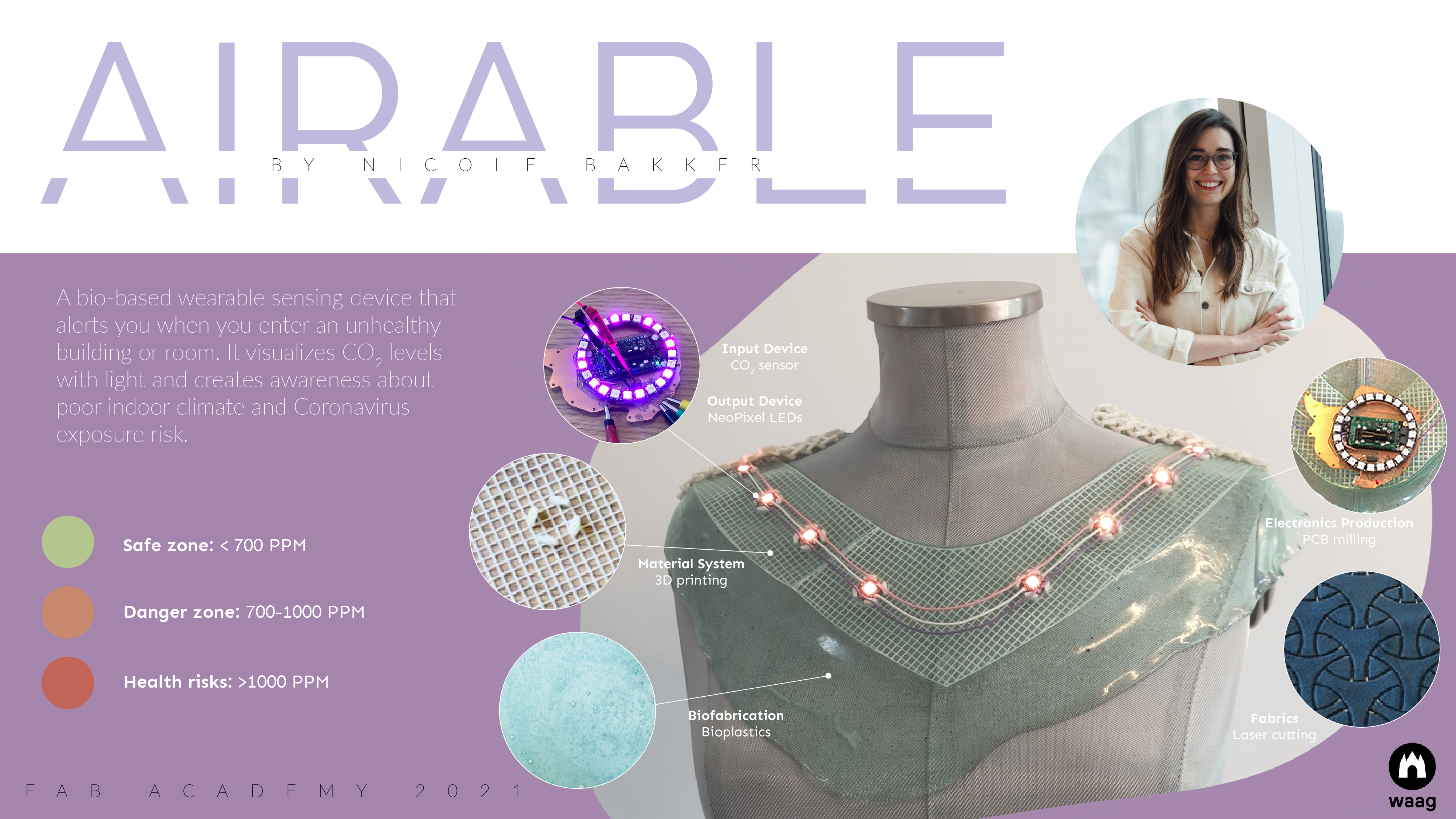
What have you designed? The Airable, a bio-based wearable for monitoring indoor air quality and Coronavirus exposure risk.
What does it do? The Airable provides visual feedback about good-medium-bad air quality with coloring LEDs based on environmental data collected by an integrated CO2 sensor.
What’s in the name? I propose Airable as a new class of wearable technology specifically designed to monitor air quality.
Here is the hero video of the final project:
And the summary slide:
Project description
This Fab Academy final project is a wearable sensing device to alert you when you enter an unhealthy building or room. It aims to create awareness about poor indoor climate and unsustainable material use in buildings. Who will use it? People who might suffer from the Sick Building Syndrome and want to improve their health. Or people who want to reduce their exposure risk of COVID-19.
The aim of this project is not to create a product that can be commercialized and mass produced. Instead, this is a one-of-its-kind artistic/maker exploration in which ancient history and modern technology will be merged. Inspiration will be drawn from my native Frisian ancestry.
It is an exploratory study at the convergence of the digital and biological. We will take a closer look at the largest sensor of our body: the skin. Our bodies are interconnected with our environment. We sense, register, and act upon external impulses. It is an interface for processing information. The sensing capabilities of the skin provide similar functions as input-output devices in electronics, yet more complex.
When our (indoor) environment is unhealthy, we also can experience acute and/or indirect health problems. The global rise of carbon emissions, and toxicity of cheap products of mass production will only add to this - as well as to the growing mountains of waste. These are all products of the linear economy. A system that’s long overdue and not conductive to our productivity, health and happiness. We need to take better care of nature, including ourselves.
Better approaches and design methods are on the rise. Yet, there still is a surprising lot of unawareness about indoor air quality. Therefore, this project places the need for a circular economy in a different perspective: tangible and physical, on a sensory level. It measures, protects and regulates, just like a skin.
System diagram and spiral development
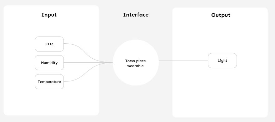
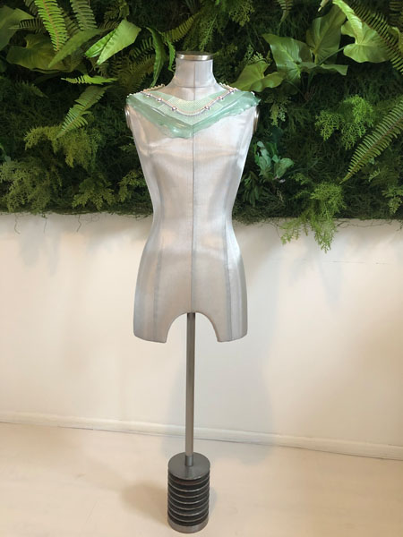
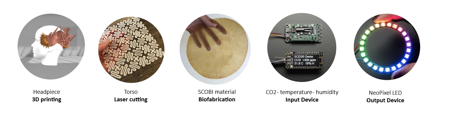
A simplified overview of the Airable is provided in the system diagram below. It has three input sensors, including CO2, humidity and temperature. The interface is the torso piece, a bio-based structure, and its output is light with integrated RGB LEDs.
I designed the Five Spiral Flower Diagram to provide guidance in working through the separate components of the final project. This is divided in Design, Hardware, Fabrication, Programming and Biomaterials. In the center, you can see the first spiral. Moving outward, more functionalities are added.
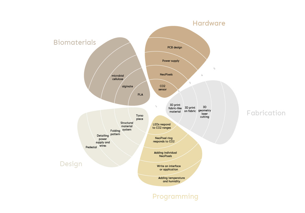
During the first weeks of Fab Academy I started with the idea to make two designs: a headpiece and a torso piece. Over the course of the weeks I narrowed this down to one wearable device positioned at the torso. This reduced complexity of the overall project and provided an opportunity to dive deeper into creating workflows for making my own materials from scratch based on Fabricademy’s resources on (bio)material production and programmable textiles.
Design inspiration
Throughout the centuries, the Frisian peoples in Northern, Eastern and Western territories could be recognized by their distinctive clothes and costumes. Nowadays no cultural references can be found in regional garments, except for an occasional Frisian flag on T-shirts, swimwear and wooden shoes called klompen. To draw attention for this lost heritage of everyday attire, one of the traditional Frisian costumes provided inspiration for this device. The pictures below were taken in the Fries Museum in Leeuwarden, The Netherlands.
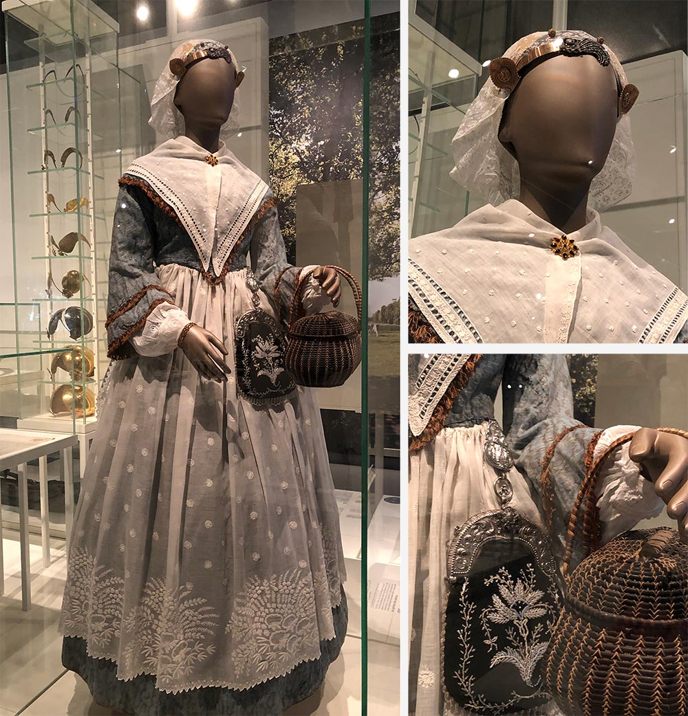
A component of this costume is the “oorijzer”, an “ear iron” which is a piece of metal headgear worn in the Netherlands during the 16th to 20th century. They were worn as part of the traditional costume and used to keep a cap in place.
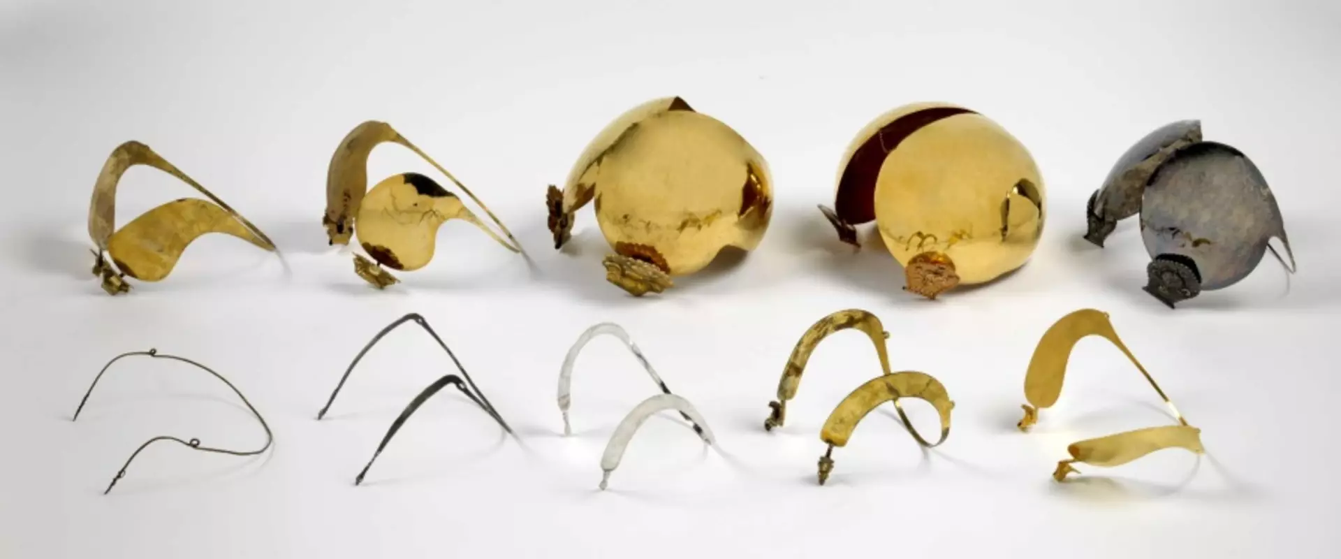
Image courtesy: Fries Museum
Lastly, Frisian embroidery. The digital archive contains a collection of over 600 embroidery patterns from the 17th to 20th century. For example, this piece made by a Frisian girl in 1860. The piece on the right was made in 1744.
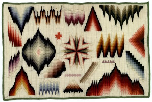
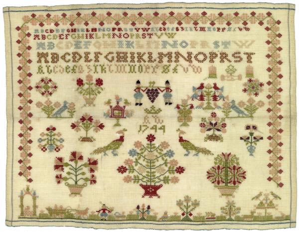
Image courtesy: Fries Museum and Tresoar
References and literature
Projects that combine carbon dioxide monitoring with design interventions in buildings or dangerous areas include:
- Building façade in São Paulo with LEDs visualizing noise and pollution.
- Room CO2 RGB LED matrix portal monitor.
- Research paper (2009) on a wearable sensing application with carbon dioxide monitoring for emergency personnel.
On March 4 2021, Studio Roosegaarde published a new project in development called Urban Sun. This urban installation promises to ‘clean public spaces of coronavirus to bring well-being’. The light can clean up 99.9% of the coronavirus, thereby making public interactions possible.
“Suddenly our world is filled with plastic barriers and distance stickers, our family reduced to pixels on a computer screen. Let’s be the architects of our new normal and create better places to meet.” - Daan Roosegaarde
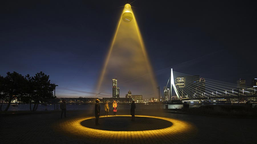
Image credits: Studio Roosegaarde
This is similar to the idea for a reinterpretation of the Frisian costume into an Airable. What if we can work with the same Far-UV 222 nm light frequency and create a personal device? For now, the first goal is to create a monitoring device that visualizes CO2 in light. In later iterations it could be interesting to add regulating functions for altering the environment. Because these types of LEDs are not available yet, it is out of scope for this final project.
Fabrics design and production
An important element of this final project is the design and manufacturing of the pattern. This is the template from which the parts of a garment are traced onto fabric before being cut out and assembled (wiki). This is something else than the texture of the material. With this final project I developed digital workflows for both. The novelty of this project is in the material system itself.
Pattern design
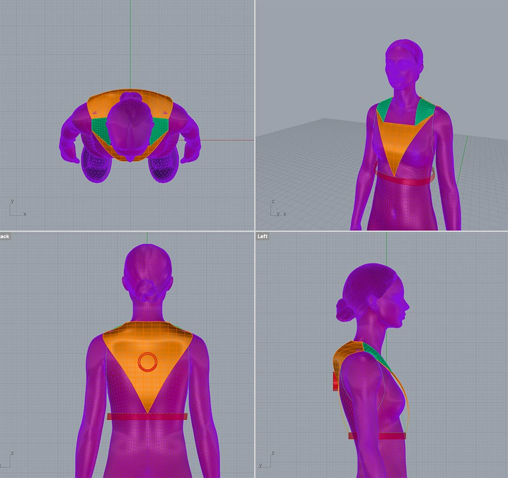
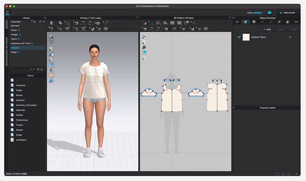
With an .obj mannequin model exported from Clo, I started with designing the wearable in Rhino software.
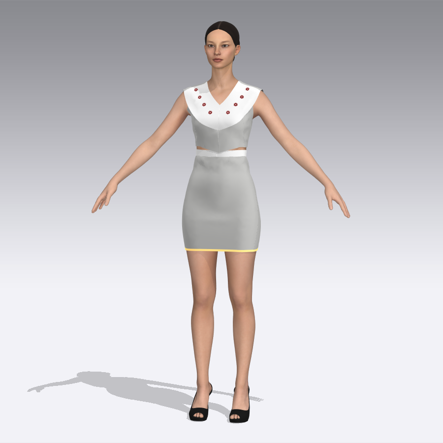
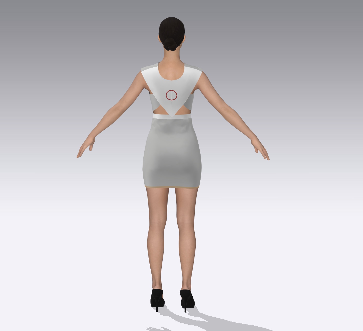
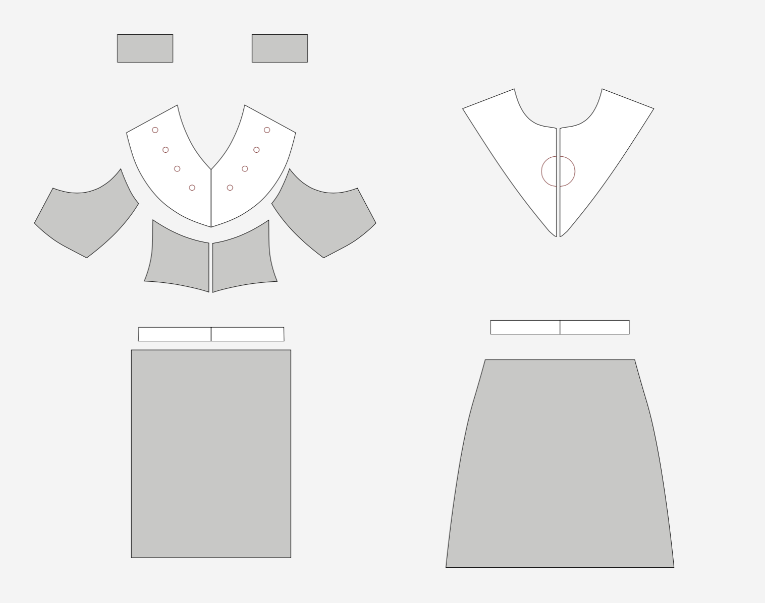
Because I wasn’t quite happy with the looks of it, I designed a less futuristic style with Clo software. The wearable is the white part. I also designed a top and skirt to dress up the avatar a little.
The pattern was then exported to PDF.
Neopixel holders
To keep the Neopixels in place on the front side of the wearable, specific holders were designed. I started with a sketch of the concept. The holders would be printed on top of the fishnet structure.
![]()
With the help of this Adafruit Fusion360 tutorial for creating snap fit cylinders and spheres I started with with reference lines and a 2D geometry in Rhino, then made surfaces out of them. Other Adafruit tutorials I watched were Snap fit Circular PCBs and Circular Snapfit cases. This Formlabs blog on designing enclosures also was a useful reference.
![]()
![]()
![]()
After completing the 2D geometry I created solids from the surfaces by extruding them. To lock the Neopixels in place, I added a notch on each one. I made sure to make it a little higher, so there would be enough space for the biomaterial to flow underneath it.
![]()
![]()
After a couple of iterations I imported the Clo pattern in Rhino for further processing and texture design. Then I positioned the Neopixels on top of the pattern.
![]()
The overall design of the front was now ready. This provided a foundation for parametric design of the fishnet texture.
Fishnet structure
During Wildcard Week I experimented with many techniques for creating programmable fabrics. In this final project I’m scaling up the fishnet tests to create a hybrid material system with 3D printed PLA and bioplastics. This fishnet pattern was created from scratch with Rhino and Grasshopper, after a lot of tests and failed procedures. First, the front was subdivided in three parts and the back in two to fit the build plate size of the 3D printer. This is 230 x 190 x 200 mm.
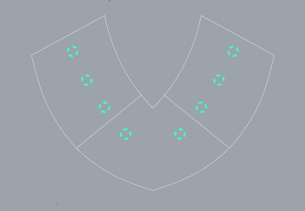
To generate useful input data for Grasshopper, five surfaces were created: three on the front and two on the back.
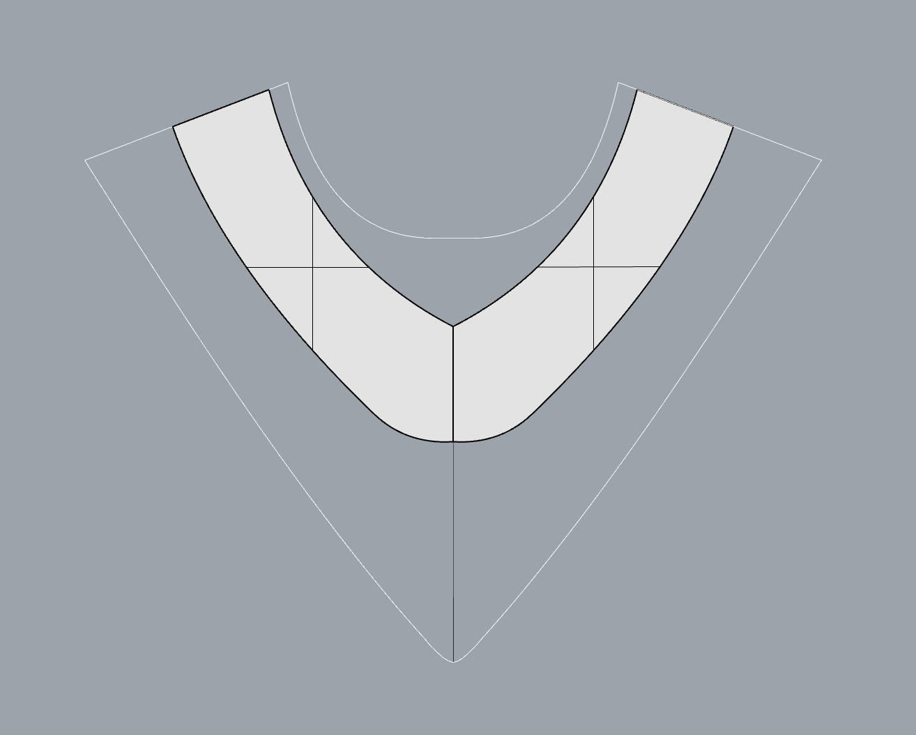
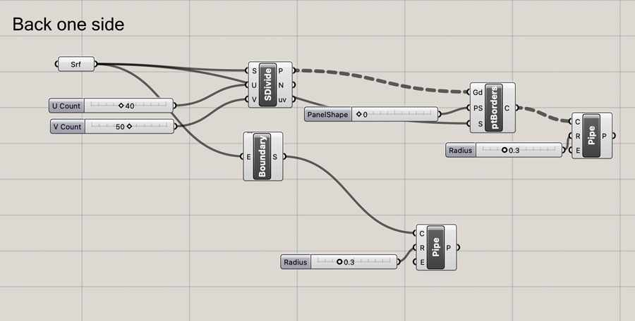
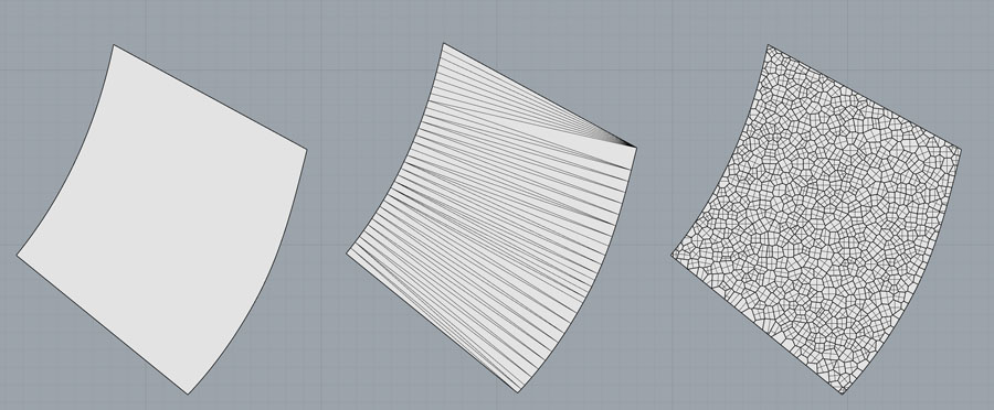
In Grasshopper, the surface is linked with a Srf component. I connected this with a Boundary component and a Pipe to create a type of solid that’s suitable for meshing later on. For a fishnet, we need intersection points. Therefore the SDivide component was added with number sliders for points in the U and V direction. These points were the input value for ptBorders, a component that creates a grid off of points. After this grid is completed, add a thickness with the Pipe function. This script might look very simple, but I spent hours and hours before I got to this point. My other attempts are documented on the bottom of this page, in the weekly progress section of week 17. For readability I decided to only show the design process of the successful model here.
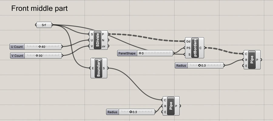
After waiting for a long time for the calculations to finish, this is how the script came out. I was relieved to see that the software was able to compute all these small solid polysurfaces!
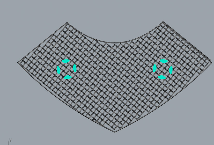
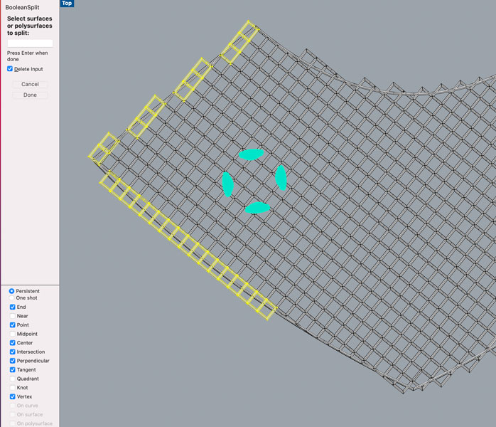
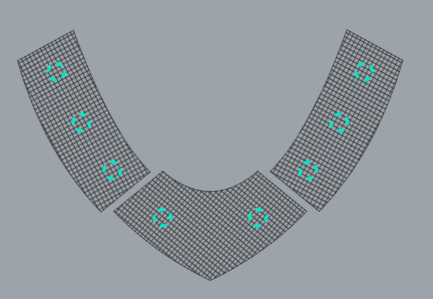
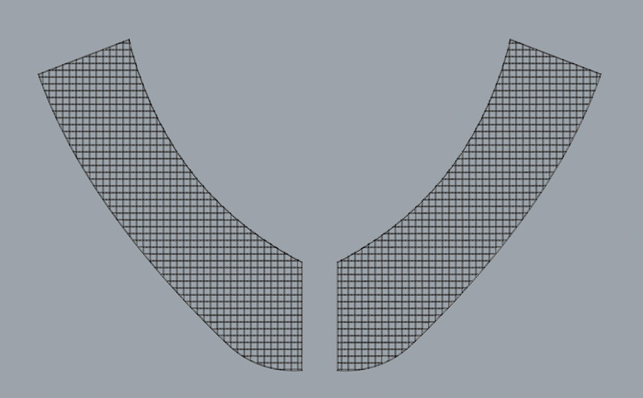
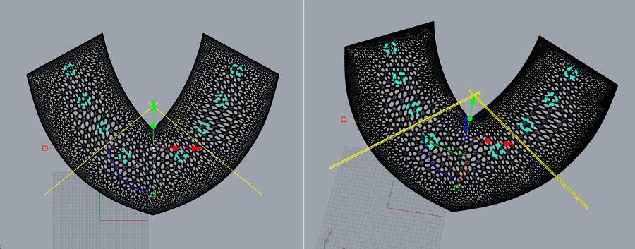
Because the border regions weren’t quite there yet I manually added squares at regions where the inner and outer pipes intersected and where the script dropped the inner squares. Next, I removed the squares that were crossing the outer pipe. In Grasshopper, the BooleanSplit function didn’t generate the desired result so I decided to apply this command in Rhino. Meaning: select all polysurfaces to split, select the cutting polysurface and then delete all items. This was a lot of work.
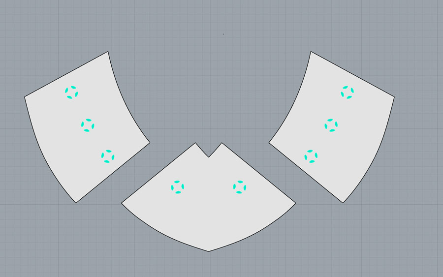
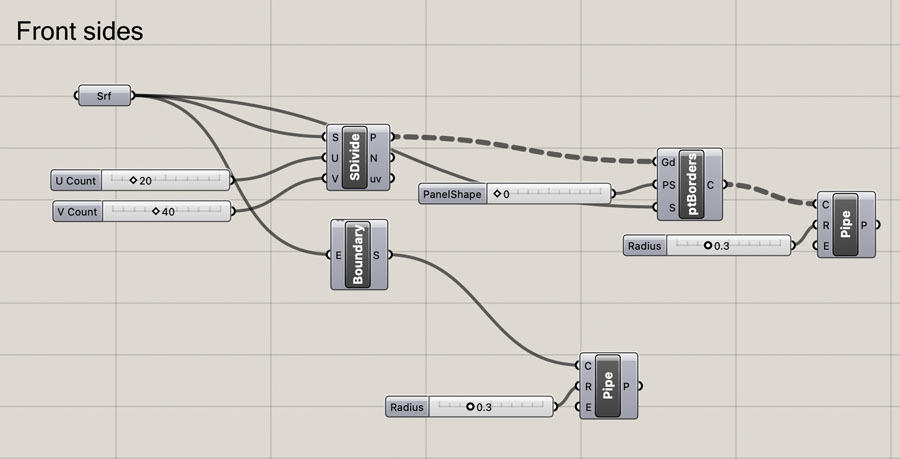
Next, I duplicated the script, linked it to the surface of the right front side, and adjusted the UV Count values until the geometry resembled the first. After this process, I baked it in Rhino and repeated the same process with adding squares and subtracting geometries. After this was finished, it was easy to get the left front side, as I could simply mirror the geometry.
The script for the two shapes on the back is the same. I repeated the procedure described above. Each time it took a lot of time to compute, as so many small geometries are created in this pattern.
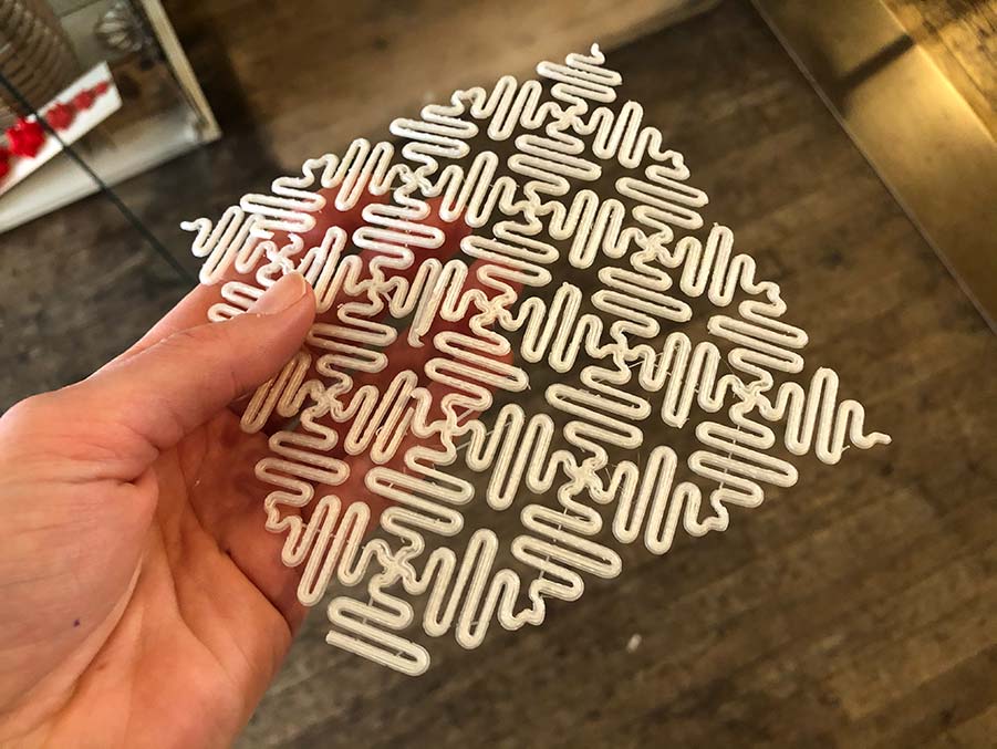
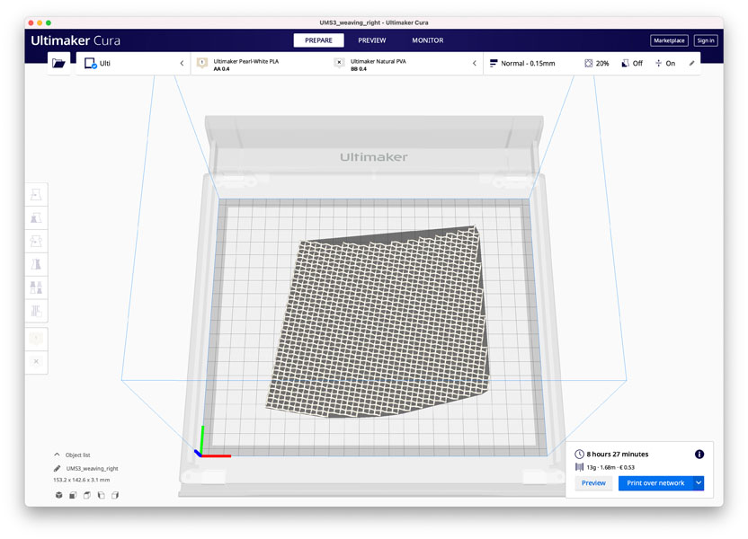
Here are the five parts in Rhino, ready for 3D printing. I created meshes and exported them as stl files.
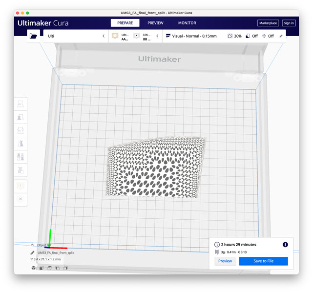
Two of the parts in Cura, showing no errors! :) I was really happy with this because earlier I suffered a lot with non-manifold models created from Rhino’s workflow.
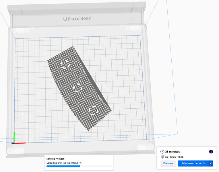
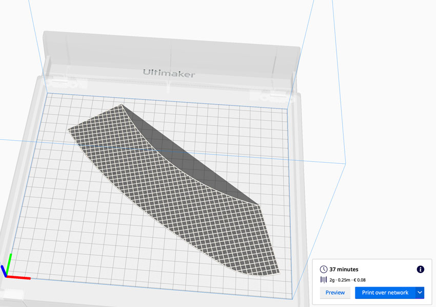
Printer settings Ultimaker S3:
- Printing profile: 0.15 visual
- No support and adhesion
- Layer height: 0.15 mm
- Initial layer height: 0.2 mm
- Line width: 0.25 mm
- Infill density: 30%
- Print speed: 20 mm/s
- Infill speed: 50 mm/s
- Wall speed: 13 mm/s
- Initial layer (print) speed: 10 mm/s
- Initial layer travel speed: 75 mm/s
- Build plate adhesion type: none
- Surface mode: both
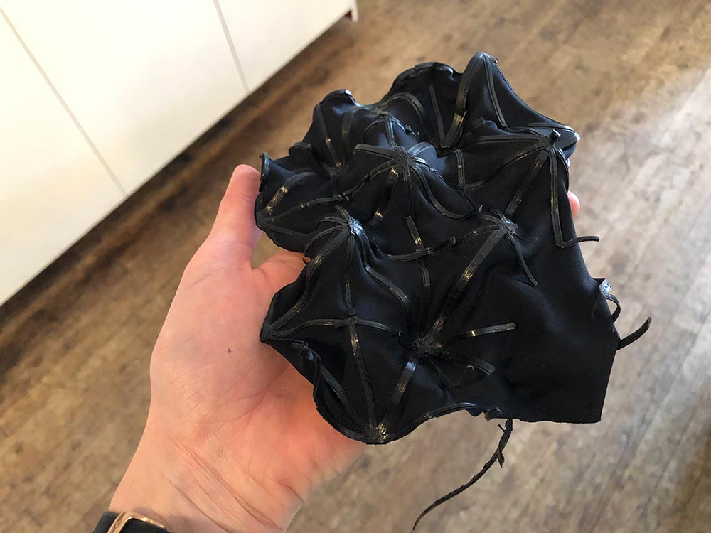
Printing time is in between 30-45 minutes per part. Below you can see the result, the front and back side after 3D printing. The reason why I selected 3D printing as a technology instead of laser cutting, is that for this geometry the laser cutting process would create a lot of waste material.
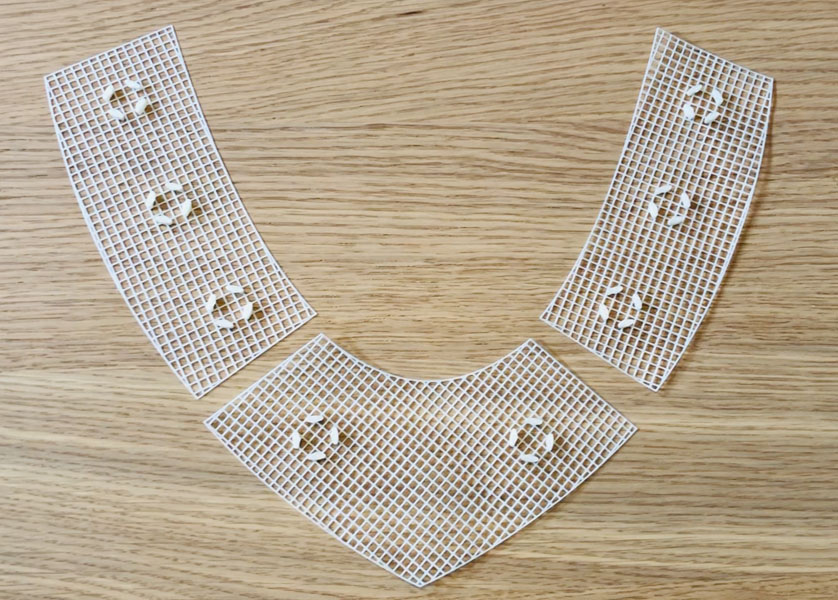
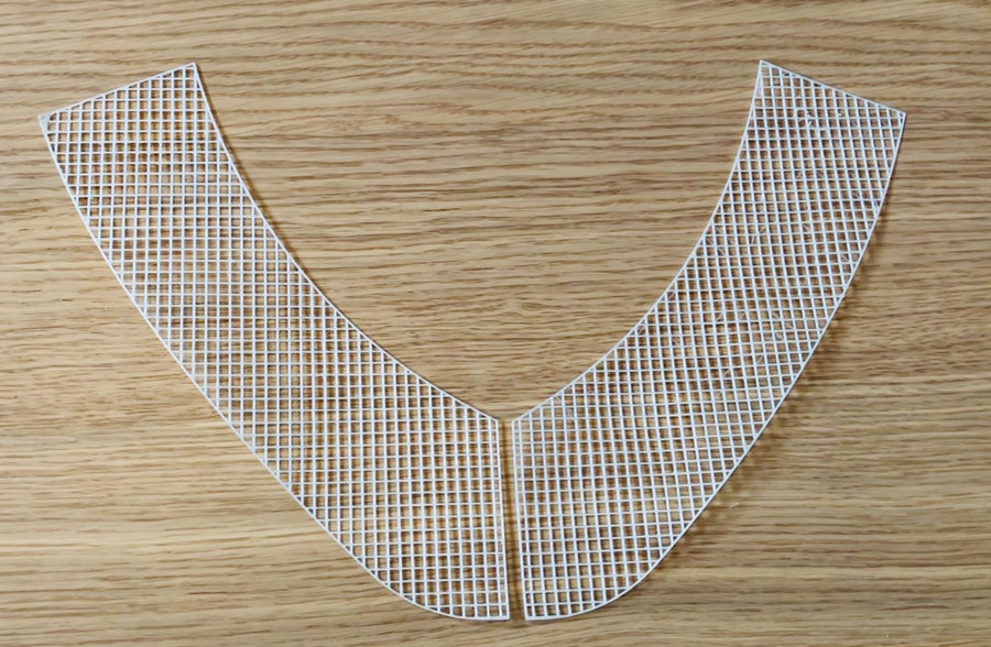
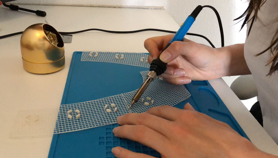
I connected the parts by gently melting them together with the heat of a soldering iron. When you do this, make sure to turn the temperature at its lowest (in my case 200 degrees Celsius) and press very softly into the material. Otherwise it will burn through and melt the PLA away.
After completing this step, the scaffolding fishnet structure is ready. Now we can add the liquid material that will solidify the pattern as one structure.
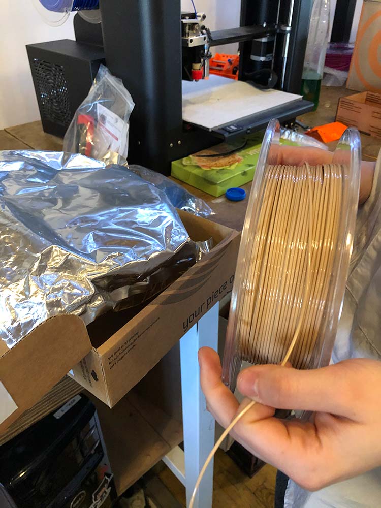
Biomaterials production
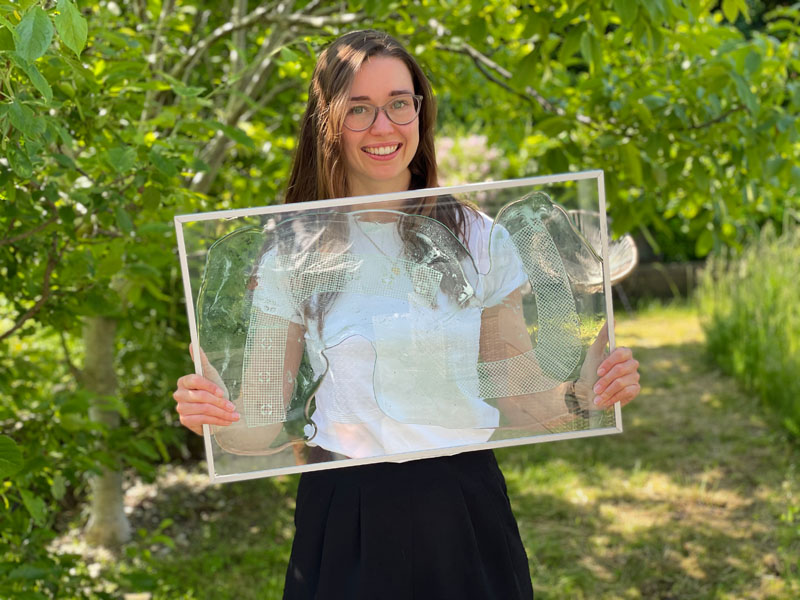
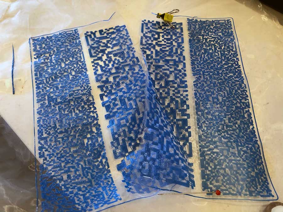
The final fabric consists of two parts: a 3D printed PLA scaffolding structure and a bioplastic. I worked with a gelatin-glycerin recipe to create the latter. In the image below I’m holding the sheets while they are still drying.
Ingredients:
- Gelatin: 100 gr
- Glycerin: 30 ml
- Water: 500 ml
- Spirulina: 3 gr
- Blue food coloring
This is the recipe:
- Heat the gelatine in the water at maximum 40 degrees Celsius, keep stirring until the gelatine fully dissolves
- Add the liquid glycerin and stir a bit more
- Add food coloring and spirulina, stir well
- Place the 3D printed structure on a flat surface
- Pour the mixture over the 3D printed structure in a continuous movement
- Let it dry for at least an hour before you continue with post-processing
In the video below you can see the production process and assembly of the sheets, along with a sneak preview of the electronics integration on the front.
Shoulder pads
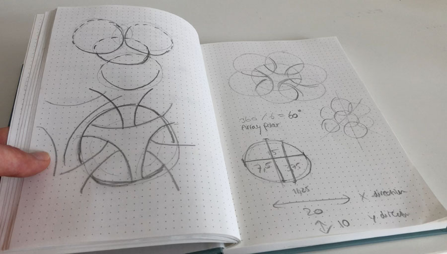
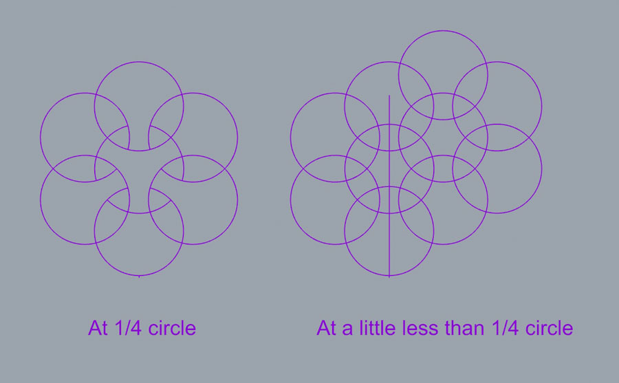
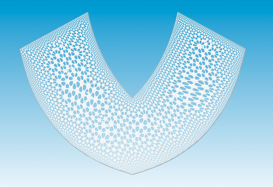
For the shoulder pads, I wanted to laser cut an interesting pattern on a fabric. My inspiration is this video of the “Breathing Facade” by Hiroya Tananka. I started with sketching out the circles and calculating the angles and distances.
In Rhino I started with drawing some guidelines for one circular structure, then deleted a couple of lines to resemble te sketch (middle image). In the third iteration I added more circles to create the internal geometry and continued from there.
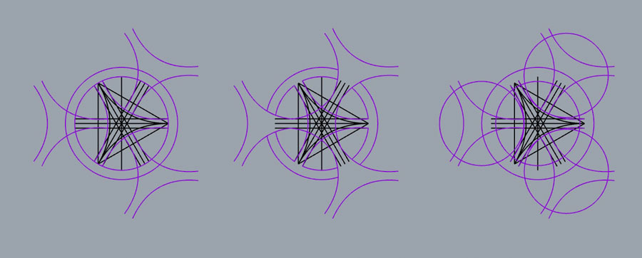
In the next step of the design process I experimented with adding more circles in a PolarArray and deleted the lines until I was satisfied with the remaining structure.
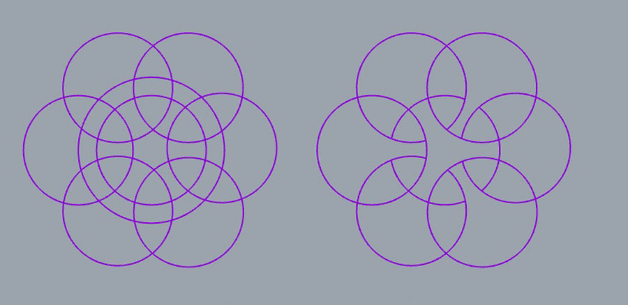
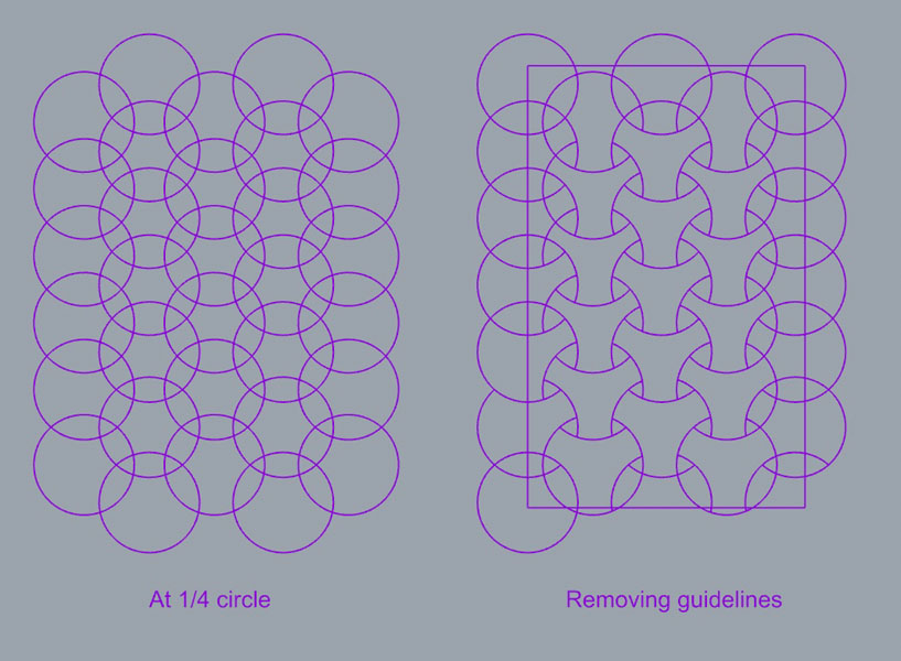
Scaling up the pattern (left) and removing the guidelines with Trim command. With this repetition the final pattern became visible. I also added a frame.
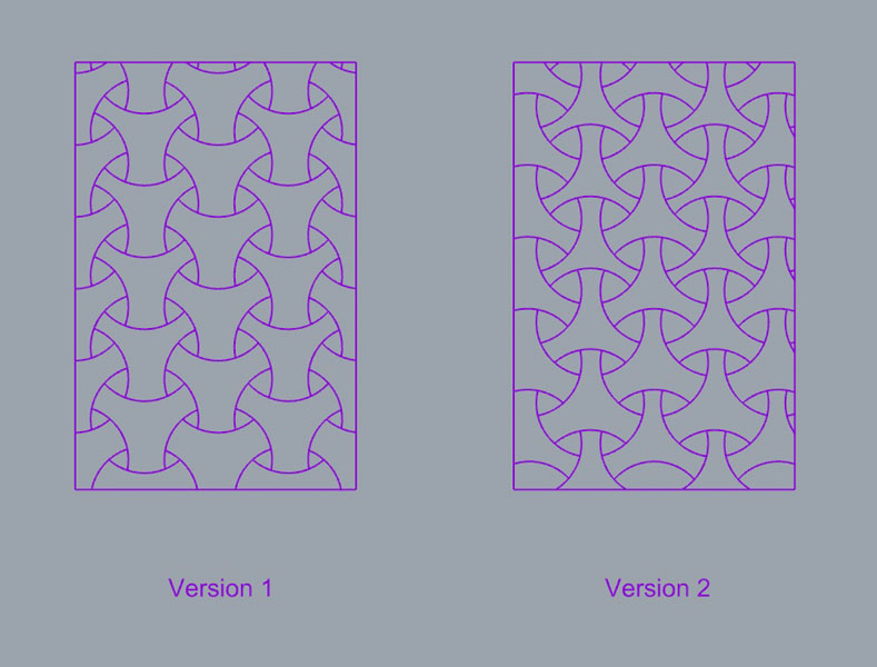
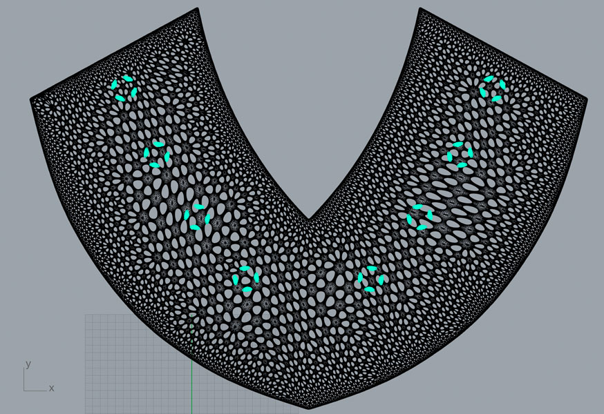
The final patterns were created by removing the shapes that intersect the frame. I created a second version and liked this more than the first. Then I exported the design in dxf and scaled it up in LightBurn to match the size of the fabric.
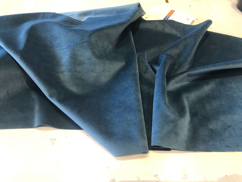
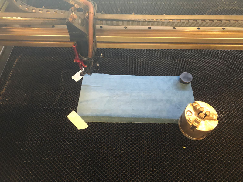
Next, I wanted to laser cut version 2 of the pattern on fabric. I had never done this before so I was very excited to see how that would go. The fabric I wanted to work with is this leftover velours curtain sample made out of recycled PET bottles.
In this step I placed the fabric on the laser cutting bed and fixed it with tape and weights. The laser cutting settings I used are:
- Speed: 500 mm/s
- Max. Power: 20%
Make sure to stay close to the laser cutter and be prepared to put out a fire if needed. In my case nothing happened and it all went very smoothly. But when you work with new materials you never know how they behave in relation to the laser. It still is fabric and might catch fire quickly. This specific sample is produced for curtains, so they get fire retardant properties in order to comply with regulations. This might not be the case with other velours materials so always be careful.
The resulting shoulder pads! Really love how they came out and I’m surprised by the level of detail. I made one extra just in case.
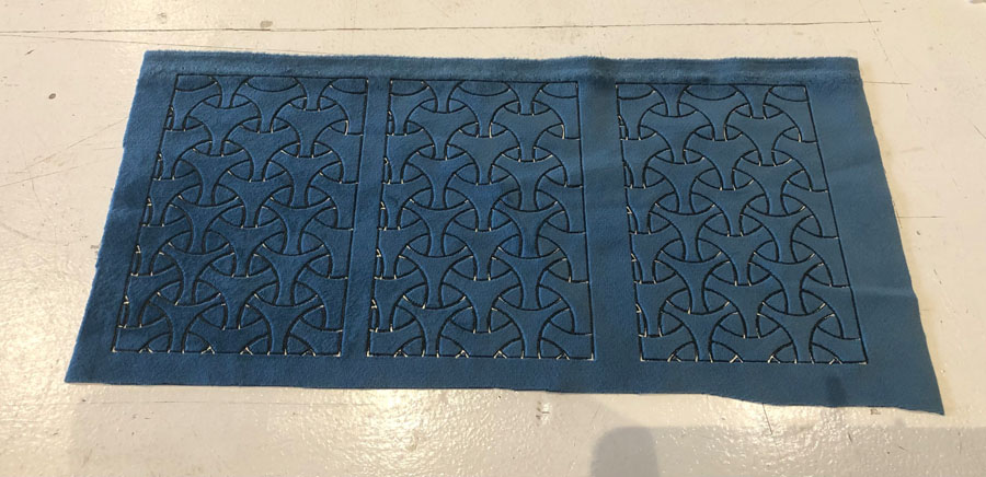
Later when I assembled the wearable I revaluated the material choice and decided to go for the chainmail structure (created in the wildcard week) instead of this fabric. It would be too distracting if I would add another color, material and texture.
Electronics
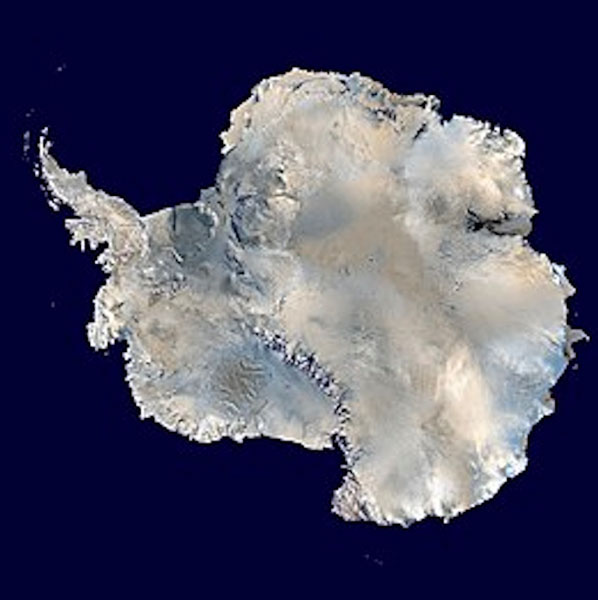
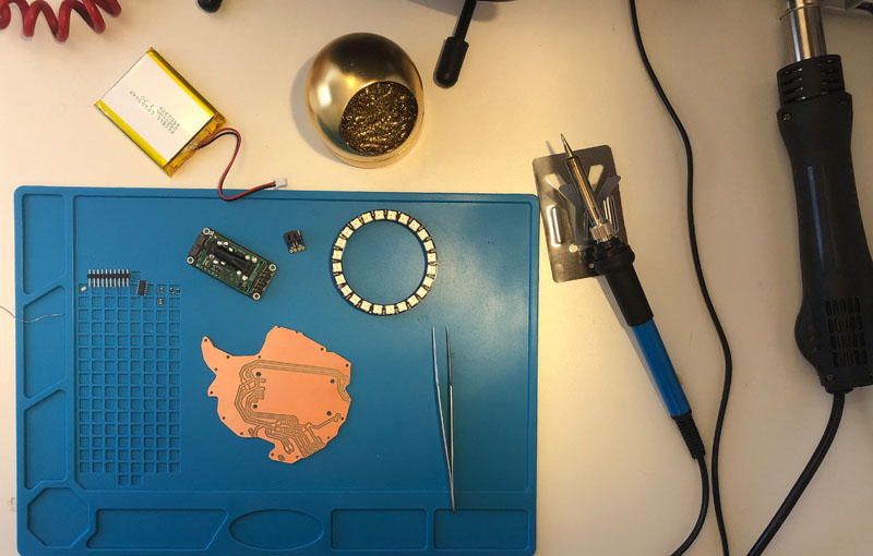
My philosophy for the PCB design was to use as little materials and components as possible, because electronics generally use most rare earth metals. The final PCB was shaped after Antarctica, as a reference to melting ice caps as a result of rising CO2 levels.
Here are the schematics in Kicad’s Eeschema. My mission to use as little components as possible seems to have worked.
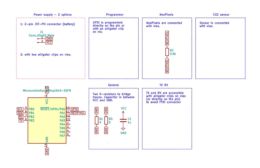
The power supply is organized in two ways to accommodate for a variety of circumstances. The first is ‘demo mode’ in which the installation can be positioned stationary for a longer period of time. In this case, power is organized with alligator clips connected to an FTDI that’s hooked up to a USB port of a laptop. This is useful for presentations and exhibitions.
The second way to power this project is with a portable 1200 mAh LiPoly battery. I downloaded Adafruit’s JST battery board from Github, opened it in Eagle and exported it as an dxf file. On the image on the right you can see how it looks after it’s imported in Kicad. With white, I redrew the outline of the JST battery connector.
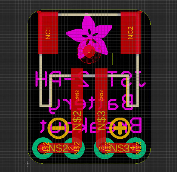
And I placed the connector on the board to fit the battery pads on the design.
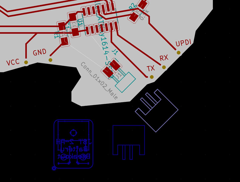
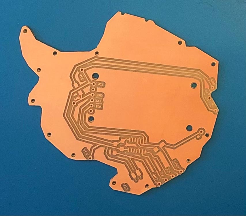
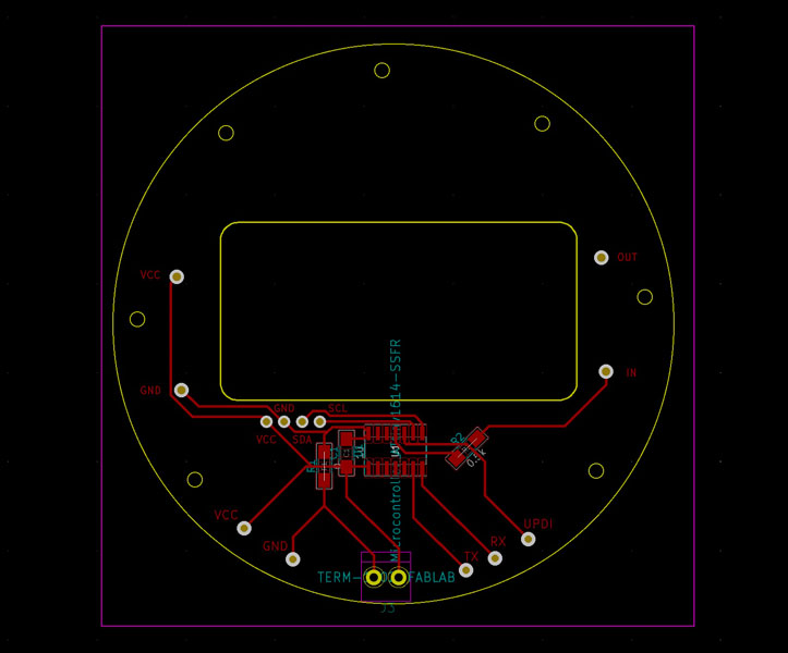
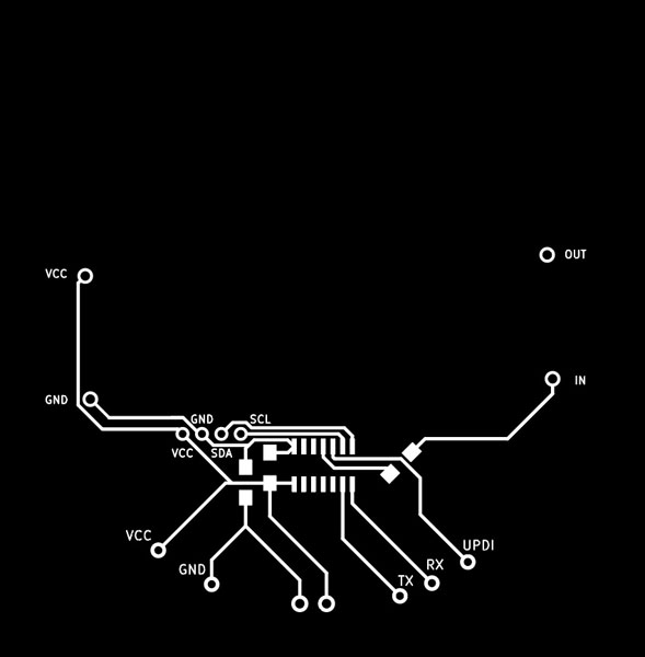
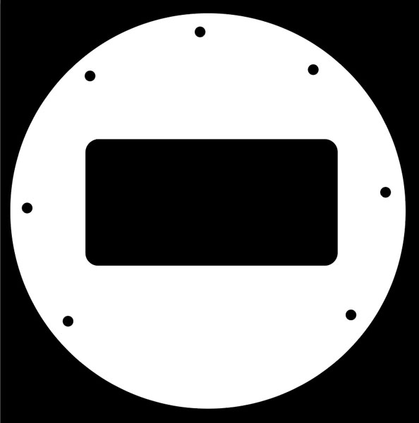
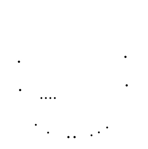
The final PCB with the outline and traces is shown below. Long tracks and two 0Ω resistor bridges were needed to create a dual power supply system, and to reach one side of the Neopixel ring. The long track on top moves around the SDC-30 sensor.
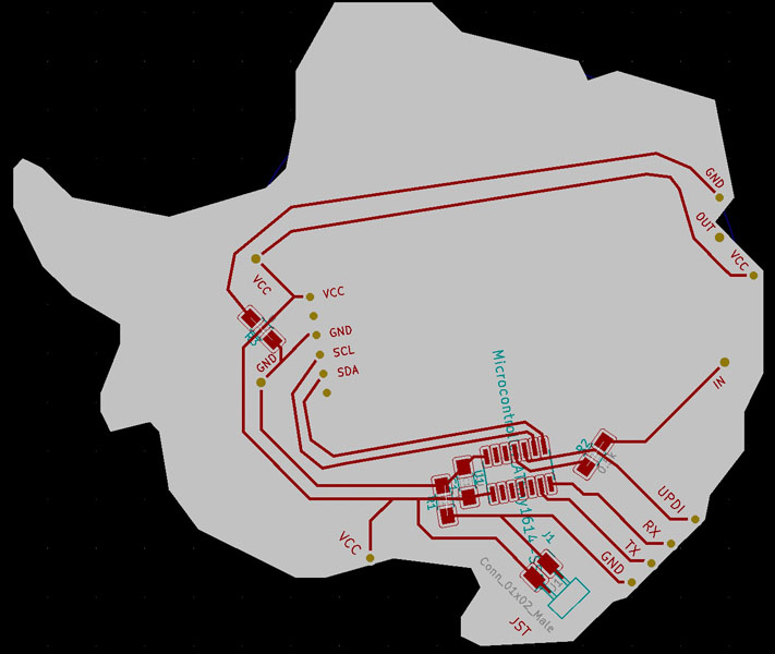
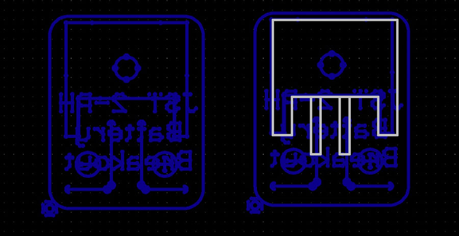
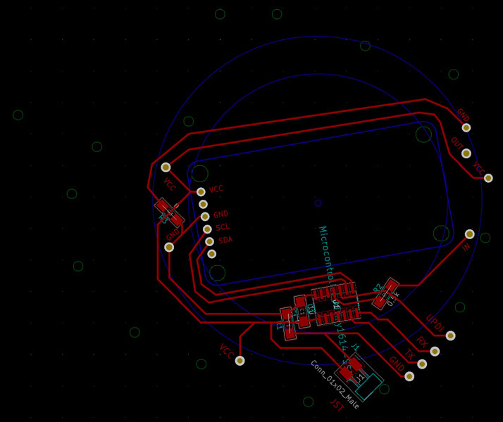
To clarify this system a bit more, below you can see the reference lines for the Neopixel ring and SCD-30 sensor. They are drawn with blue in another layer and will not be milled. The small circles in green are the through-holes.
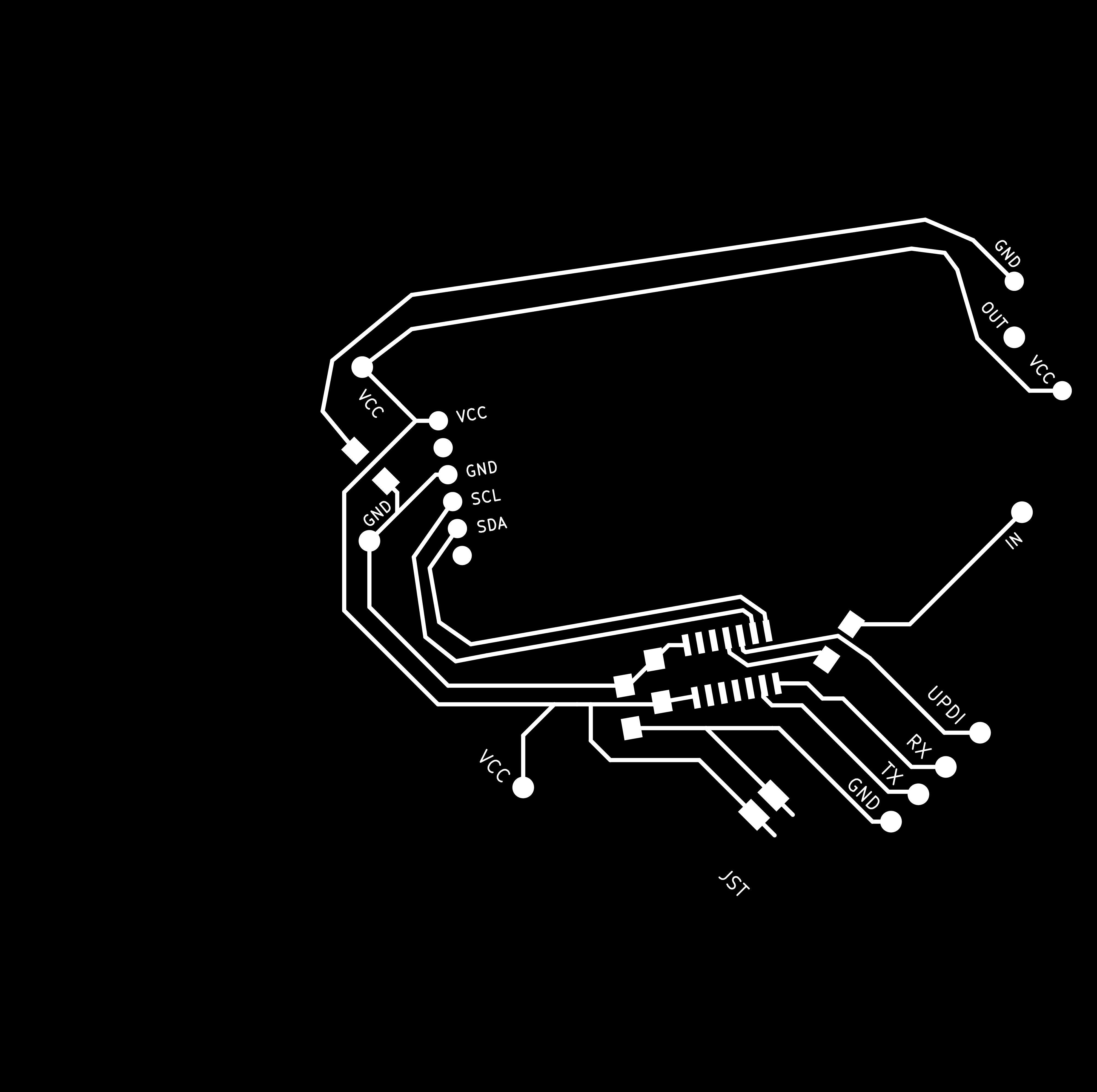
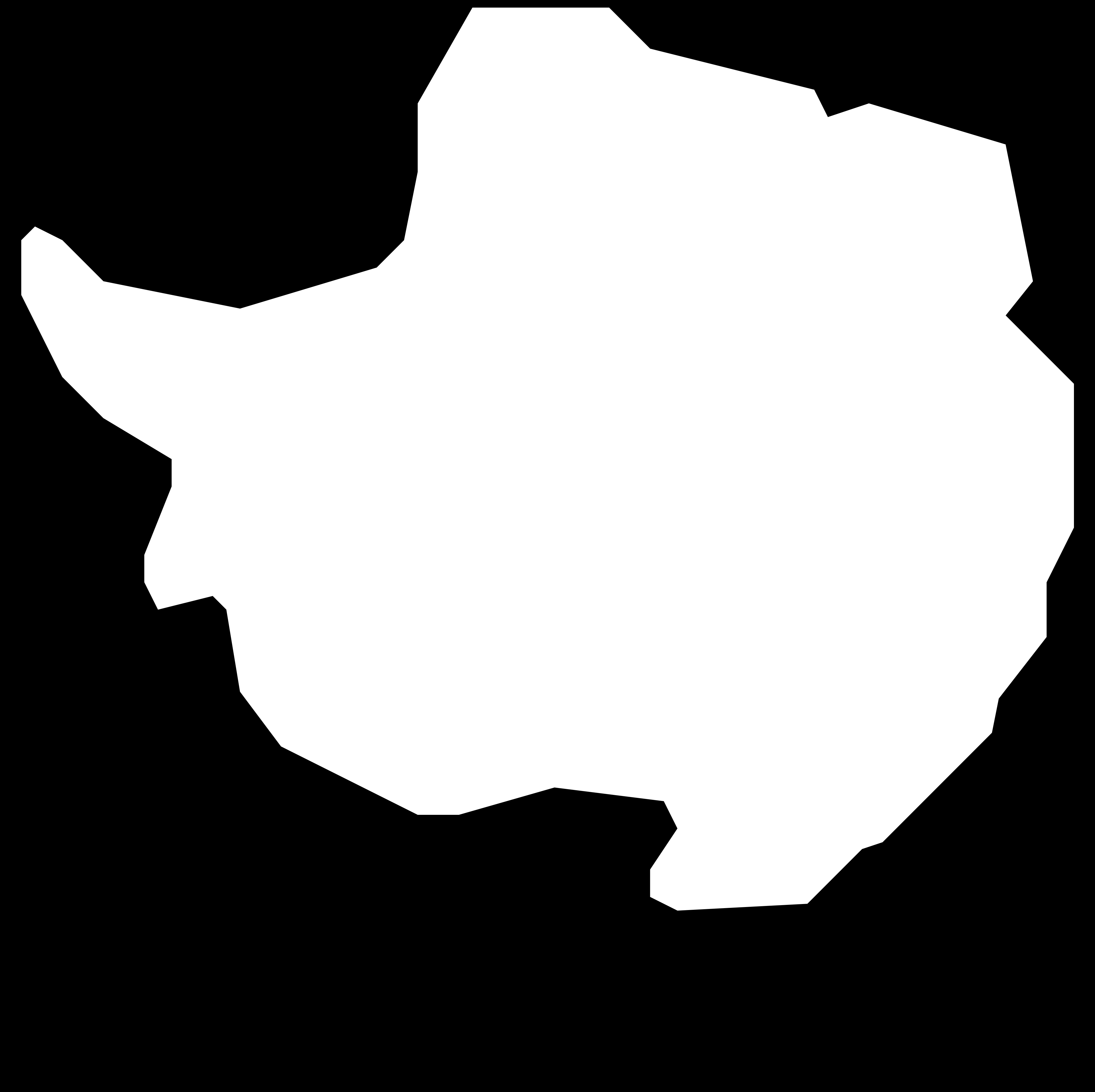
Here are the final png images of the Traces, Outline and Through-holes.
After milling, the board was ready for soldering. Below you can see all components.
Front and back side after soldering.
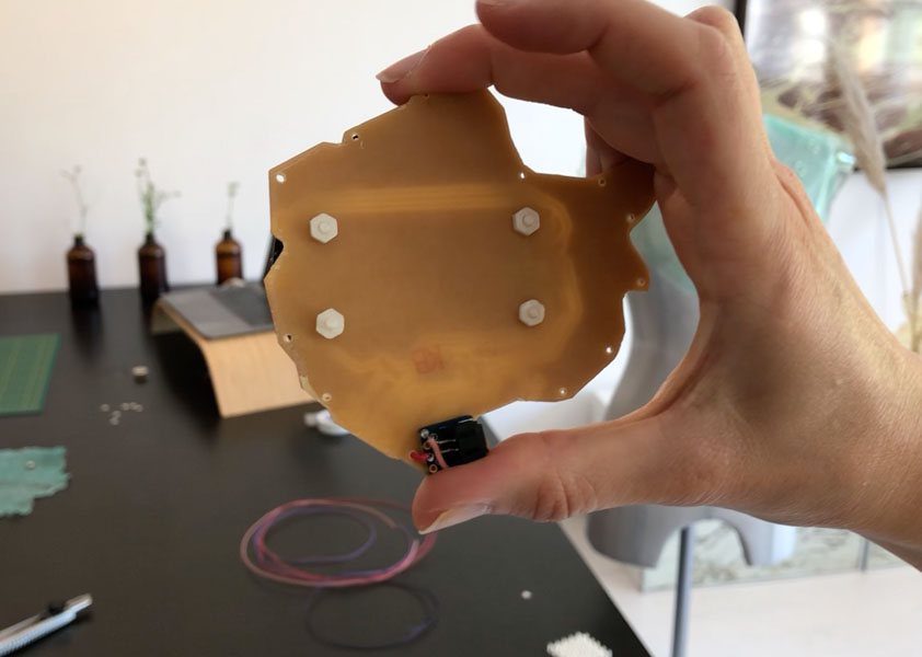
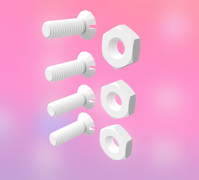
I didn’t have M2.5 bolts and nuts so I looked them up on McMasterCarr and 3D printed them. I also made a cover for the Neopixel ring.
![]()
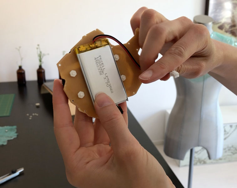
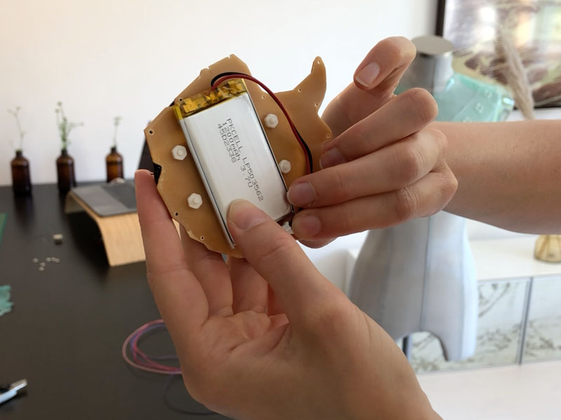
This is how the battery can be connected.
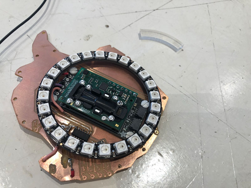
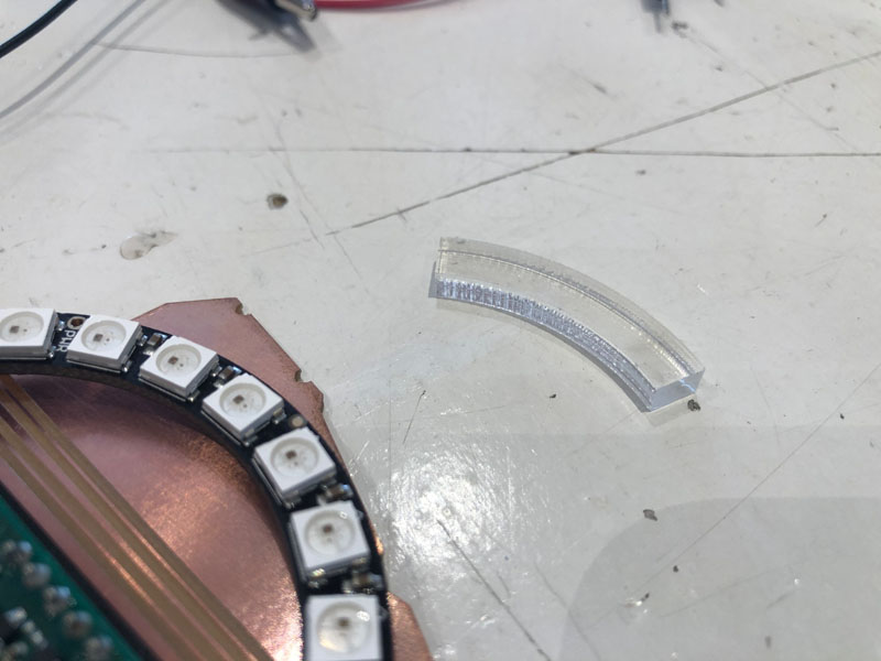
To firmly connect the Neopixel ring to the PCB a part of the ring was laser cut in acrylic. I glued this on the PCB.
Embedded programming
The Airable visualizes atmospheric CO2 values with light, and indicates when levels are too high. During Output Devices I elaborated on the implications of CO2 emissions on our health. Based on the research papers cited there I defined the CO2 threshold values of my sensor at:
- Mode 1 (green LED): <700 ppm
- Mode 2 (orange LED): 700-1000 ppm
- Mode 3 (red LED): >1000 ppm
Here is the full code of the Antarctica board:
// Antarctica Carbon2Color SCD30
// Visualizes atmospheric CO2 in three colors: green, orange and red.
// Nicole Bakker
// Fab Academy 2021


// Based on sample code: Basic demo for readings from Adafruit SCD30

#include <Adafruit_SCD30.h>

Adafruit_SCD30  scd30;

#include <tinyNeoPixel.h>

tinyNeoPixel strip = tinyNeoPixel(32, 8, NEO_GRB + NEO_KHZ800);


#define PIN B0
#define PIN B1
#define PIN 8

const int low = 700;
const int high = 1000;

void setup() {

  // CO2 sensor setup

  Serial.begin(115200);
  while (!Serial) delay(10);     // will pause Zero, Leonardo, etc until serial console opens

  Serial.println("Adafruit SCD30 test!");

  // Try to initialize!
  if (!scd30.begin()) {
    Serial.println("Failed to find SCD30 chip");
    while (1) { delay(10); }
  }
  Serial.println("SCD30 Found!");


  // if (!scd30.setMeasurementInterval(10)){
  //   Serial.println("Failed to set measurement interval");
  //   while(1){ delay(10);}
  // }
  Serial.print("Measurement Interval: ");
  Serial.print(scd30.getMeasurementInterval());
  Serial.println(" seconds");


// Neopixel setup

  strip.begin();
  strip.show(); // Initialize all pixels to 'off'

}//void setup


void loop() {

  if (scd30.dataReady()) {
    Serial.println("Data available!");

    if (!scd30.read()){ Serial.println("Error reading sensor data"); return; }

    // Blink LED1 blue to indicate that the sensor is on
    colorWipe(strip.Color(0, 0, 255), 50); // Blue
    delay(100);


    // CO2 sensor standard

    Serial.print("Temperature: ");
    Serial.print(scd30.temperature);
    Serial.println(" degrees C");

    Serial.print("Relative Humidity: ");
    Serial.print(scd30.relative_humidity);
    Serial.println(" %");

    Serial.print("CO2: ");
    Serial.print(scd30.CO2, 3);
    Serial.println(" ppm");
    Serial.println("");


    // Activate LED at CO2 levels

    if (scd30.CO2 < low) { //low - blink green LED
        Serial.println("CO2 below 700ppm");
        colorWipe(strip.Color(0, 255, 0), 50); // Green
    } else if (scd30.CO2 > high) { //high - blink red LED
        Serial.println("CO2 above 1000ppm");
        colorWipe(strip.Color(255, 0, 0), 50); // Red
    } else { //medium - blink orange LED
        Serial.println("CO2 in between 700-1000 ppm");
        colorWipe(strip.Color(255, 70, 0), 50); // Orange
    }//else

    // regular code

  } else {
        //Serial.println("No data");
  }//else

  delay(100);
}//void loop


//////////////////// Color functions //////////////////////

 // Fill the dots one after the other with a color
void colorWipe(uint32_t c, uint8_t wait) {
  for (uint16_t i = 0; i < strip.numPixels(); i++) {
    strip.setPixelColor(i, c);
    strip.show();
    delay(wait);
  }//for i
}//void color
In the video below you can see how this works in practice. First, I connected the TX and RX to read out the data in the Serial Monitor.
Programming is done directly on the pins of the microcontroller with small clips. No connector pins are needed so it saves space and materials.
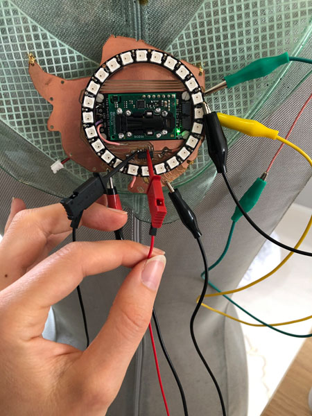
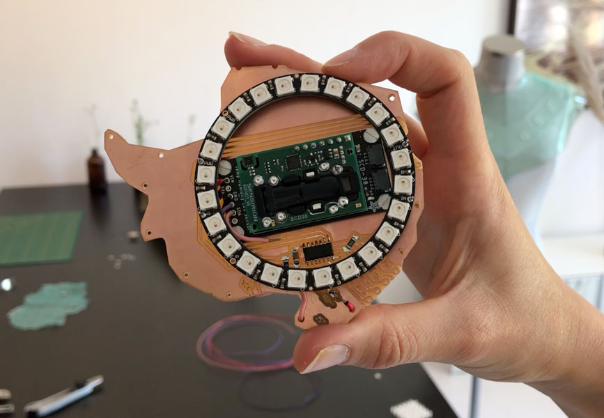
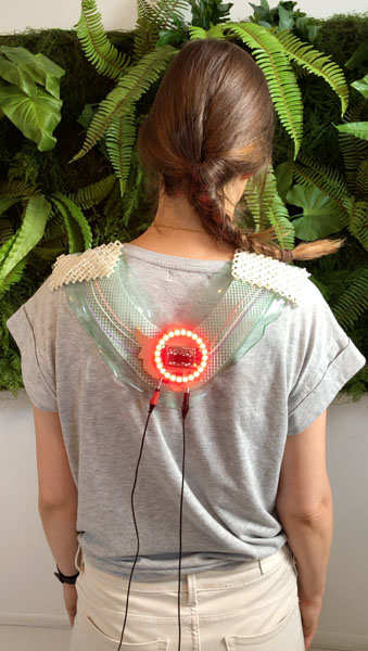
Here is the full system in operation with the Neopixels connected, before sewing the wires of the back:
Bill of Materials
Throughout the weeks, all materials will be added here. This includes a bill of materials.
| Component | Qty | Vendor | Costs |
|---|---|---|---|
| CO2 sensor module SCD30 | 1x | Adafruit, Brooklyn (NY) | €44.66 |
| NeoPixel ring 24 RGB LED | 100 x 100 mm | Adafruit, Brooklyn (NY) | €19.95 |
| 8 sewable NeoPixels | 1 sheet of 20 | Adafruit, Brooklyn (NY) | $34.95 |
| Conductive thread 3 ply | 1x | Adafruit, Brooklyn (NY) | $9.95 |
| ATtiny1614 | 1x | DigiKey ordered by Waag | €0.54 |
| Capacitor 1μF | 1x | DigiKey ordered by Waag | €0.23 |
| Resistor 5k Ω | 1x | DigiKey ordered by Waag | €0.08 |
| Resistor 0 Ω | 1x | DigiKey ordered by Waag | €0.08 |
| LiPoly battery 1200 mAh 3.7V | 1x | Adafruit, Brooklyn (NY) | €9.95 |
| JST-PH 2-Pin SMT Right Angle Breakout Board | 1x | Adafruit, Brooklyn (NY) | €1.50 |
| USB LiIon/LiPoly charger - v1.2 | 1x | Adafruit, Brooklyn (NY) | €12.50 |
| Copper sheet for PCB milling | 1x | Digikey ordered by Waag | €7.43 |
| Pearl White PLA filament | 1x | Ultimaker, The Netherlands | € 33.00 |
| Biomaterials: glycerine, gelatine, food coloring | 1x | The Netherlands | €10.00 |
Not used and/or for prototyping purposes:
| Component | Qty | Vendor | Costs |
| Shinyei Model PPD42NS Dust Sensor | 1 | Seeed Studio | Second-hand, new prize €15 |
| Arduino Uno | 1 | Arduino | Second-hand, €20 before tax |
| Small electronics components: UPDI, FTDI, solder etc. | 1x | DigiKey ordered by Waag, The Netherlands | €15.00 |
The CO2 sensor is the most expensive component of the system. For the final project, I will make a small material impact analysis of all components and materials used.
Weekly progress
In the section below my weekly progress on the final project is documented. For me, the most challenging elements are related to electronics and programming as I’m an absolute beginner. As a structural engineer, I’m comfortable with designing/making large things from bulky materials such as concrete, wood and steel. To broaden my skill set I decided to choose a small final project, make it with ‘soft’ and intricate materials and focus on including a variety of electronics components.
During each week, I started with documenting an initial idea or first experiment. As my experience with the machines and skill set builds, I added more advanced tests in the weeks that followed. These later additions are timestamped.
First sketches (week 1)
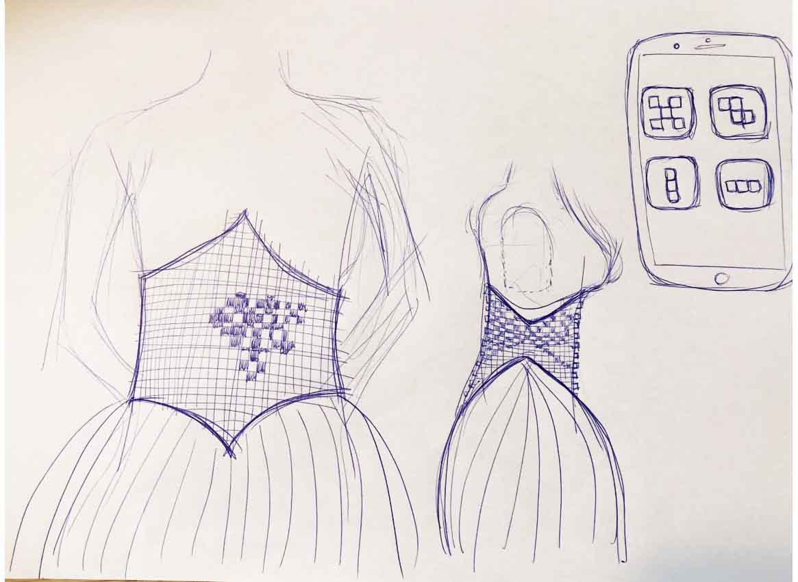
In Week 1b Principles and Practices of the Fab Academy, we made sketches of a potential final project. Below is a hand drawn sketch with a first concept.
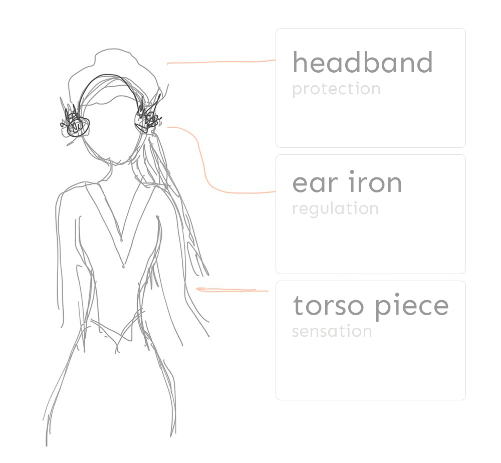
In the second sketch, three functions of the skin are mapped on three parts of the final project. These are: sensation, protection and regulation.
Computational Design (week 2)
This is a beginning of the Rhino/Grasshopper design with a mannequin, the headpiece and the body piece. The mannequin will be milled or lasercut, depending on the material choice later on in the project. The headpiece and body part will be made with a combination of lasercutting, 3D printing and perhaps molding and casting.
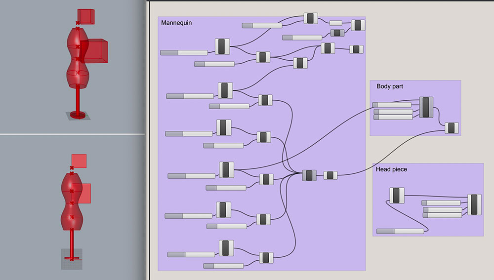
The ‘oorijzer’ design below was made in Gravity Sketch, a VR design application available on Steam.
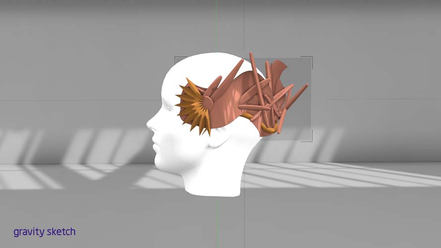
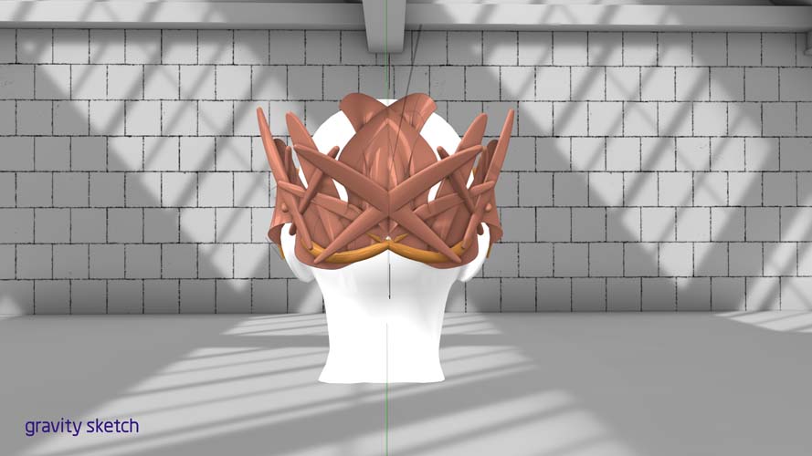
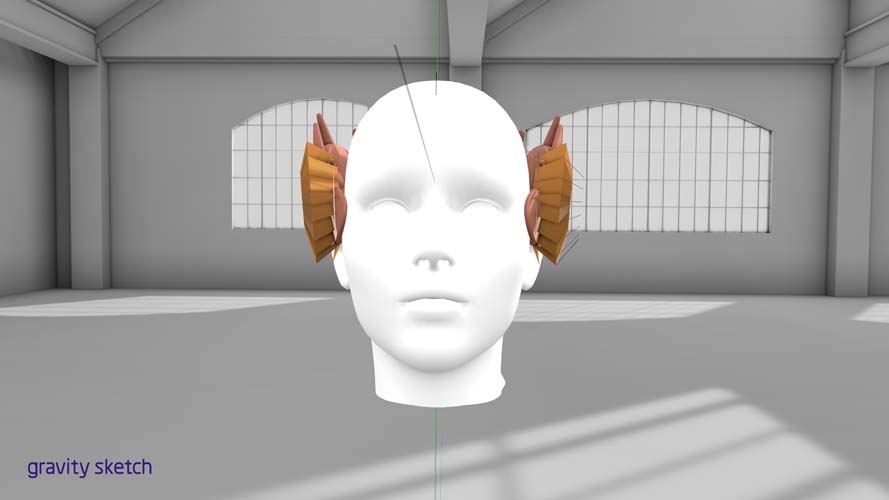
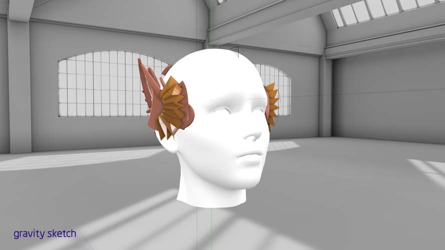
Designing in VR is more powerful than I expected. I will try to manufacture this version soon!
Computer-Controlled Cutting (week 3)
In preparation for next week’s assignment of milling PCB’s, I experimented with cutting copper material on a vinyl cutter. This is a first test for creating wearable electronics. Nadya Peek wrote a tutorial on How to make flexible vinyl cut circuits. A description of the vinyl cutting PCB workflow is as follows:
- Design constrains for the circuit
- Cutting the circuit
- Moving your circuit onto a base
- Fixing your circuit to the base
- Weeding the circuit
- Soldering the circuit
USB stick on copper
In this first experiment, I skipped step 1 and downloaded the traces test and USB file from week 4’s class page. Following step 2 of this procedure, I cut the design on the Roland vinyl cutter at Waag with the settings allowed for this week. The goal for this week is to get to know the machine workflow and speed/pressure settings.
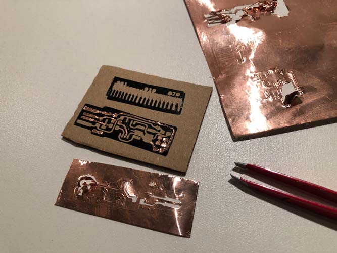
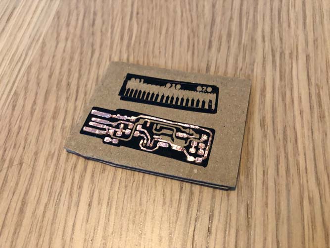
It was challenging for the vinyl cutter to create the traces. In certain areas the knife didn’t cut all the way through and in other it dragged the traces along the copper. I will retry this process later.
Electronics Production (week 4)
During this week, it’s too early for me to make a PCB for the final project, because I don’t have enough knowledge about electronics to know what components and configuration I need. The PCB fabrication process will be added here when we progress further into the weeks, learn how to design a PCB (week 6) and how to do the embedded programming (week 8). The following sensors will be added to measure environmental data and provide visual feedback and, if possible, remediation.
3D Scanning and Printing (week 5)
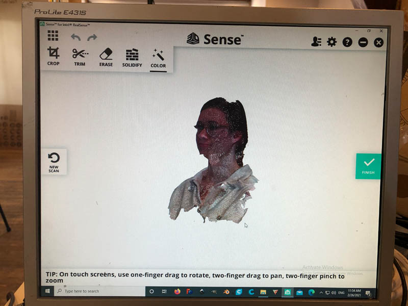
3D scanning
The plan for 3D scanning is to scan my head (for setting the right dimensions in Rhino) and to scan the ear iron from the museum (to adjust the design in Grasshopper and Rhino). Unfortunately, the 3D scans of my head weren’t very good. For 3D scanning the ‘oorijzer’ I contacted the museum. Due to the lockdown in the Netherlands it’s not possible to visit the museum on appointment yet. Update March 22: an appointment is in the making.
3D printing: VR design
The file created in VR is now post-processed in Rhino, to prepare for 3D printing.
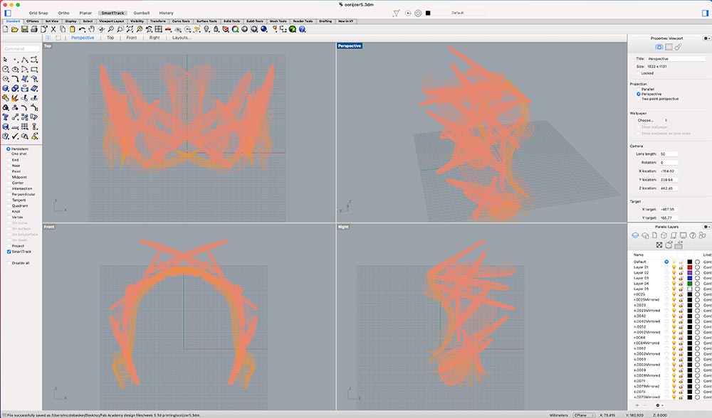
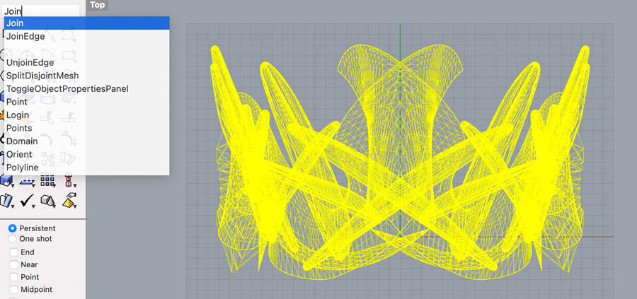
However, there are some issues with open meshes.
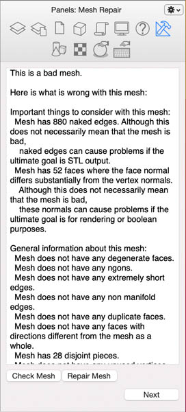
Use Join and Weld commands to repair the paths.
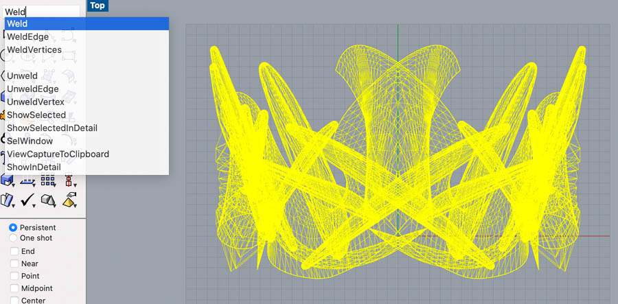
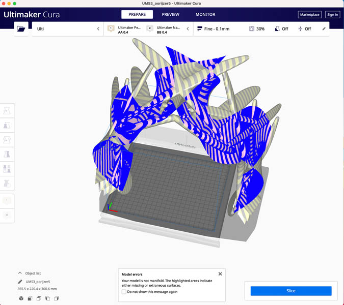
In Cura, the file still has model errors.
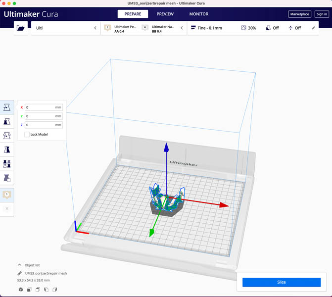
A new prototype will be made soon.
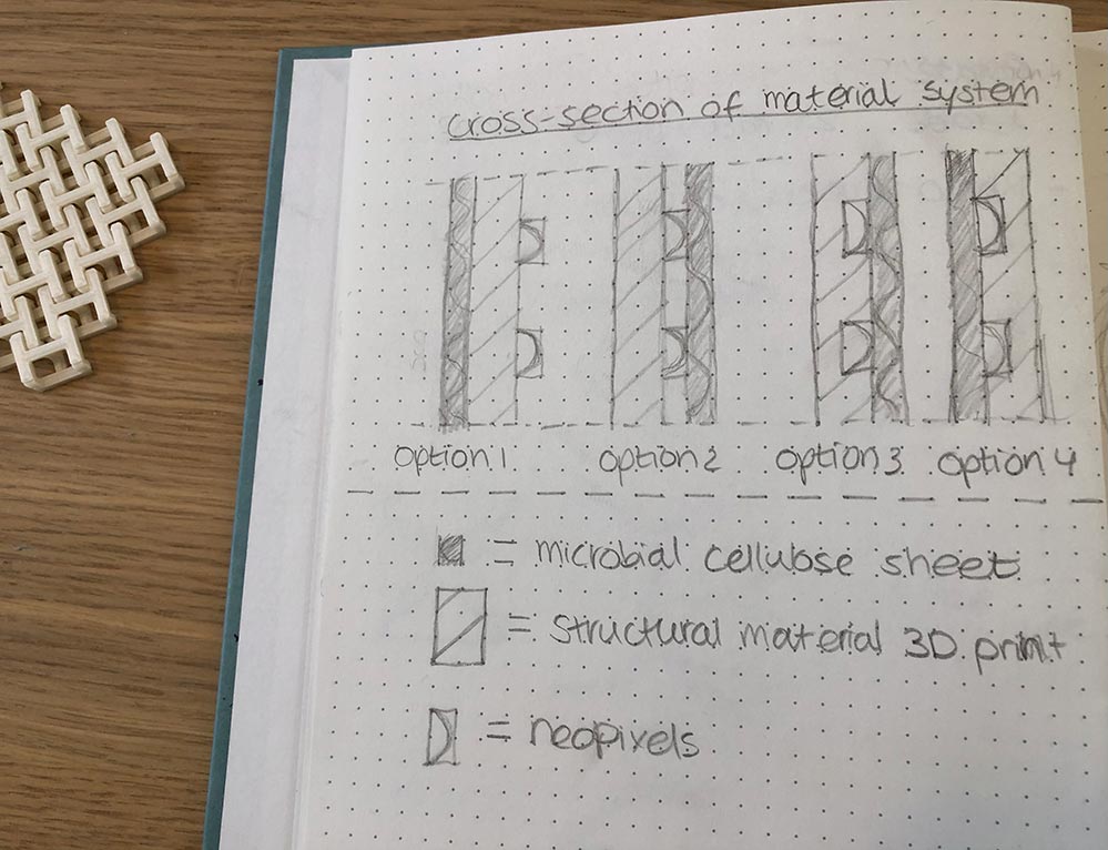
3D printing: fabrics design
This week, I researched a variety of techniques for 3D printing a fabric-like product. The Textile Lab at Waag was a great source of inspiration.
Option 1: 3D printing on fabric
Option 2: Textile-like geometry.
Option 3: Flexible filament. At Waag, we have Flexfill 98A 1,75 mm in Powder Beige color.
The design pattern of this week’s assignment will be applied to the body, with one of the above fabrication techniques. Wires, sensors and LEDs will be integrated in the pockets on the backside.
Electronics Design (week 6)
For the PCB(‘s) in my final project, I’m looking into devices and fabrication methods suitable for wearables.
3D printing PCB’s
- 3D printing PCB
- Flexible PCB article by AdaFruit
Ultraviolet light (far-UVC) sensor
The fact sheets of the URBAN SUN project from Daan Roosegaarde are published online.
The science behind URBAN SUN is based on multiple peer-reviewed journal articles authored by scientists from Columbia University and Hiroshima University. The research shows that specific ultraviolet light (far-UVC) with the wavelength of 222nm can reduce the presence of viruses, including various strains of coronavirus and influenza, up to 99.9%. Even though traditional 254nm UV light is harmful, this specific light of 222nm is considered safe for both people and animals.
The following is a shortlist of the research articles which served as the scientific inspiration for Urban Sun.
- Source 1: Nature article “Far-UVC light: A new tool to control the spread of airborne-mediated microbial diseases”
- Source 2: Nature article “Far-UVC light (222nm) efficiently and safely inactivates airborne human coronaviruses”
- Source 3: Hiroshima University article ‘Study shows first proof that a safer UV light effectively kills virus causing COVID-19’
- Source 4: Columbia University article “Far UVC light safely kills airborne coronaviruses”
So what is this and can this be used in the final project? On February 1, 2021 the FDA published an article on UV Lights and Lamps: Ultraviolet-C Radiation, Disinfection, and Coronavirus.
DigiKey search to LED Emitters - Infrared, UV, Visible.
Computer-Controlled Machining (week 7)
Due to the wearable nature of this final project, the large milling machine will probably not be used for creating the small parts. However, what could be milled is a mannequin torso. In the Fabrics Lab in Waag, there is an example.
In week 2, I spent a lot of time searching for a good free 3D CAD model download of a female torso. This was quite hard and I ended up with a guy.
Software for designing clothing:
- CLO 3D fashion designing software
- MakeHuman is an open source platform.
- Valentino is open source pattern drafting software.
With CLO 3D, you can enter your own sizes and export the torso as a CAD file. This is an eye-opener and will improve the design workflow significantly. I measured my sizes and exported the model as an .obj file.
Embedded Programming (week 8)
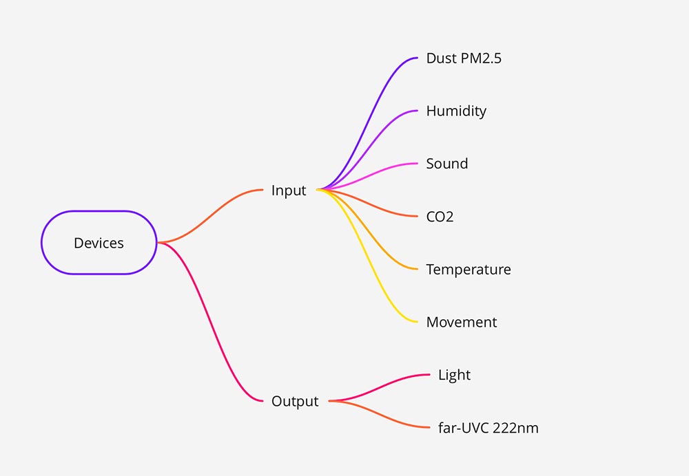
This week is crucial for learning more about the sensors. It is my first exposure to embedded programming. The following sensors and devices will be implemented in the final project (depending on availability):
- Humidity
- Temperature
- PM2.5
- CO2
- LED
A sensor for temperature and humidity is included in my Arduino starter kit, so I’m going to start with this dht11 temperature and humidity sensor. I’m working with Arduino prototype first, and once all sensors and components are working I will fabricate my own board(s).
In Dutch, will be translated to English: “De DHT11 is een goedkope en populaire sensor voor het meten van temperatuur en vochtigheid. Het de module vereist 3 verbindingen met de Raspbery Pi: 3,3 V; GND en een GPIO-invoerpin. Aangezien het uitgangssignaal 3,3 V is, kan dit rechtstreeks worden aangesloten op een GPIO-ingangspin van de Raspberry Pi. Temperatuurbereik is 0-50 ° C (+/- 2 ° C) en vochtigheidsbereik is 20-90% (+/- 5%). De sensor is vrij langzaam en heeft een beperkte nauwkeurigheid, maar het is een ideale sensor voor uw experimenten.”
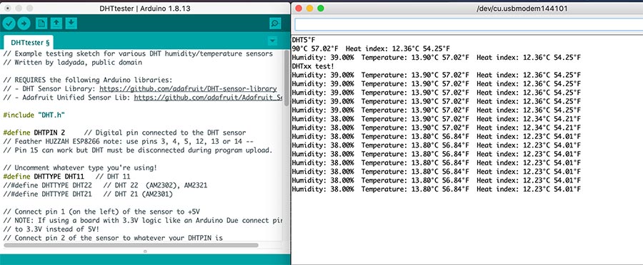
Better explanation is on the Arduino forum, How to Connect DHT11 Sensor With Arduino Uno. I completed the wiring according to the example:
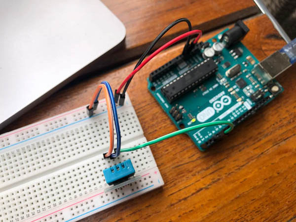
And tested the DHTtester program that came with the Adafruit library. The sensor works!
Then I found an Adafruit tutorial on RGB LEDs. I followed the steps and was able to create this:
Mechanical and Machine Design (week 9)
During these two weeks my focus was fully on the group assignment in which we built an interactive lamp that responds to light.
Input Devices (week 10)
The input device is a CO2 sensor, the Adafruit SCD-30 - NDIR CO2 Temperature and Humidity Sensor. Measurements are shown on an OLED display.
Molding and Casting (week 11)
Possible design directions with biomaterials:
- Fabric-like 3D printing (materials: TPE, regular PLA, filaflex)
- 3D print on fabric
- 3D printing on bio-based sheet (materials: scobi or mycelium)
Fabrication:
Output Devices (week 12)
A NeoPixel ring and sewable NeoPixels for visualizing CO2 values.
Here with a more hysteric program:
This is after I programmed it to work together with the internal LEDs and the sensor:
Here is the code of the NeoPixel ring that responds to CO2 values:
// Carbon2Color SCD30 internal LEDs
// Visualizes atmospheric CO2 in three colors: green, orange and red.
// Nicole Bakker
// Fab Academy 2021


// Based on sample code: Basic demo for readings from Adafruit SCD30

#include <Adafruit_SCD30.h>

Adafruit_SCD30  scd30;

#include <tinyNeoPixel.h>

tinyNeoPixel strip = tinyNeoPixel(24, 8, NEO_GRB + NEO_KHZ800);


#define PIN B0
#define PIN B1
#define PIN 8

int button = A3;
int LED1 = A4;
int LED2 = A5;
int LED3 = A6;
int LED4 = A7;

const int low = 700;
const int high = 1000;

void setup() {

  // CO2 sensor setup

  Serial.begin(115200);
  while (!Serial) delay(10);     // will pause Zero, Leonardo, etc until serial console opens

  Serial.println("Adafruit SCD30 test!");

  // Try to initialize!
  if (!scd30.begin()) {
    Serial.println("Failed to find SCD30 chip");
    while (1) { delay(10); }
  }
  Serial.println("SCD30 Found!");


  // if (!scd30.setMeasurementInterval(10)){
  //   Serial.println("Failed to set measurement interval");
  //   while(1){ delay(10);}
  // }
  Serial.print("Measurement Interval: ");
  Serial.print(scd30.getMeasurementInterval());
  Serial.println(" seconds");

  // Internal LED setup

  pinMode (LED1, OUTPUT);
  pinMode (button, INPUT_PULLUP);
  pinMode(LED2,OUTPUT);
  pinMode(LED3,OUTPUT);
  pinMode(LED4,OUTPUT);


// Neopixel setup

  strip.begin();
  strip.show(); // Initialize all pixels to 'off'

}//void setup


void loop() {

  if (scd30.dataReady()) {
    Serial.println("Data available!");

    if (!scd30.read()){ Serial.println("Error reading sensor data"); return; }

    // Blink LED1 blue to indicate that the sensor is on
    colorWipe(strip.Color(0, 0, 255), 50); // Blue
    digitalWrite(LED1,HIGH);
    delay(100);
    digitalWrite(LED1,LOW);
    delay(100);


    // CO2 sensor standard

    Serial.print("Temperature: ");
    Serial.print(scd30.temperature);
    Serial.println(" degrees C");

    Serial.print("Relative Humidity: ");
    Serial.print(scd30.relative_humidity);
    Serial.println(" %");

    Serial.print("CO2: ");
    Serial.print(scd30.CO2, 3);
    Serial.println(" ppm");
    Serial.println("");


    // Activate LED at CO2 levels

    digitalWrite(LED2,LOW);
    digitalWrite(LED3,LOW);
    digitalWrite(LED4,LOW);

    if (scd30.CO2 < low) { //low - blink green LED
        Serial.println("CO2 below 700ppm");
        digitalWrite(LED2,HIGH);
        colorWipe(strip.Color(0, 255, 0), 50); // Green
    } else if (scd30.CO2 > high) { //high - blink red LED
        Serial.println("CO2 above 1000ppm");
        digitalWrite(LED4,HIGH);
        colorWipe(strip.Color(255, 0, 0), 50); // Red
    } else { //medium - blink orange LED
        Serial.println("CO2 in between 700-1000 ppm");
        digitalWrite(LED3,HIGH);
        colorWipe(strip.Color(255, 70, 0), 50); // Orange
    }//else

    // regular code

  } else {
        //Serial.println("No data");
  }//else

  delay(100);
}//void loop


//////////////////// Color functions //////////////////////

 // Fill the dots one after the other with a color
void colorWipe(uint32_t c, uint8_t wait) {
  for (uint16_t i = 0; i < strip.numPixels(); i++) {
    strip.setPixelColor(i, c);
    strip.show();
    delay(wait);
  }//for i
}//void color
Networking and Communications (week 13)
During this week, I started with biomaterial production.
Supplies needed: [x] boxes (one that is as straight as possible - 1:30:00 min) [x] culture plates [x] cloth [x] weight (acrylic piece) [x] elastic band / clips [x] ph meter: 3.5 pH or less [x] ethanol [x] wipes [x] apple cider vinegar [x] scobi [x] sugar [x] water:
Monday may 10 9.00 AM found a scobi on a fermenting facbook group. 11.00 AM bought boxes for the scobi’s and collected other supplies. 21.30 PM start with preparing the box. Done at 00:30 AM.
Recipe:
- 7 liters of water
- 9 bags of green tea
- 700 gr sugar
- little bit of apple cider vinegar
Measurements:
- pH: 7
- Temp: 35 degrees Celsius
- After adding apple cider vinegar: pH 3
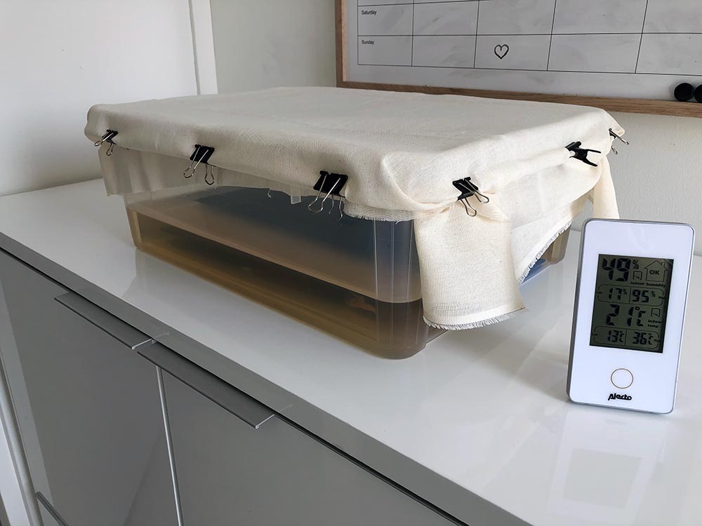
Unfortunately the sheet turned moldy and I had to toss it.
Interface and Application Programming (week 14)
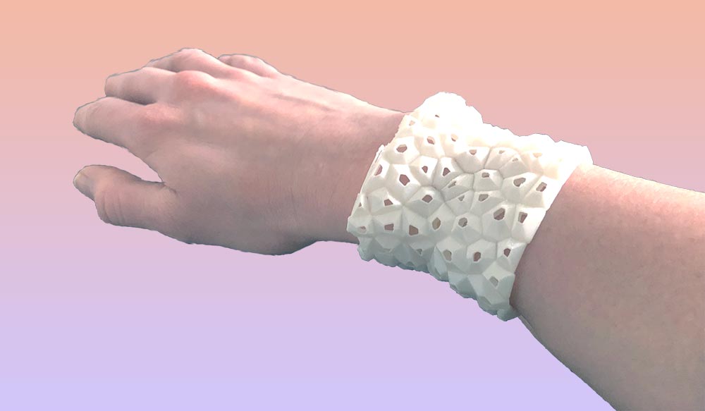
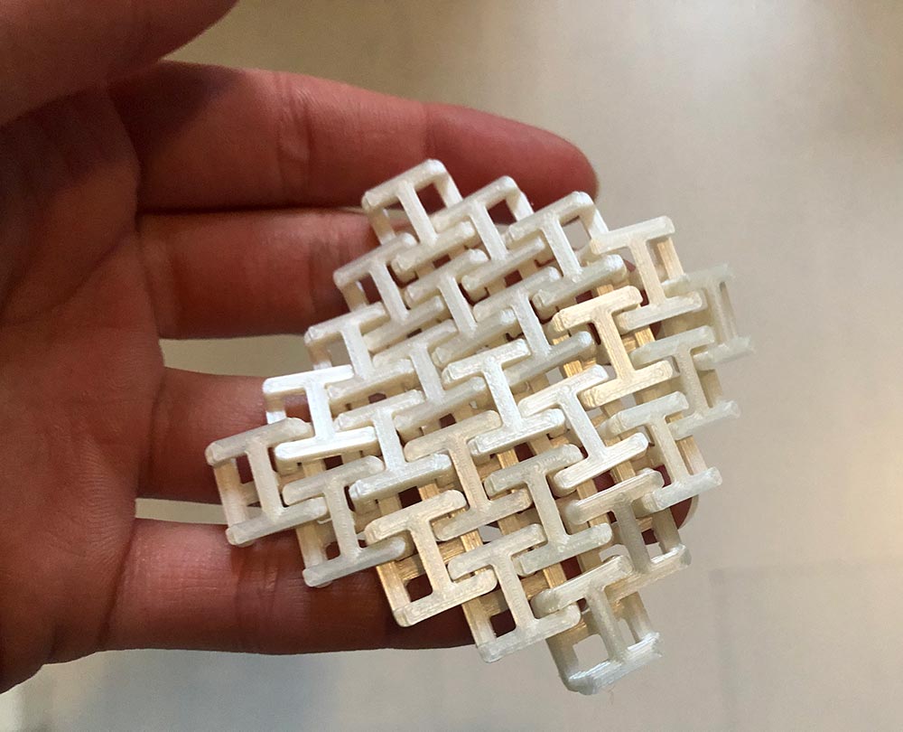
In this week I worked on a structural material.
To provide structural integrity to the design, I prototyped an interlocking unit that can be replicated. Here are two sketches.
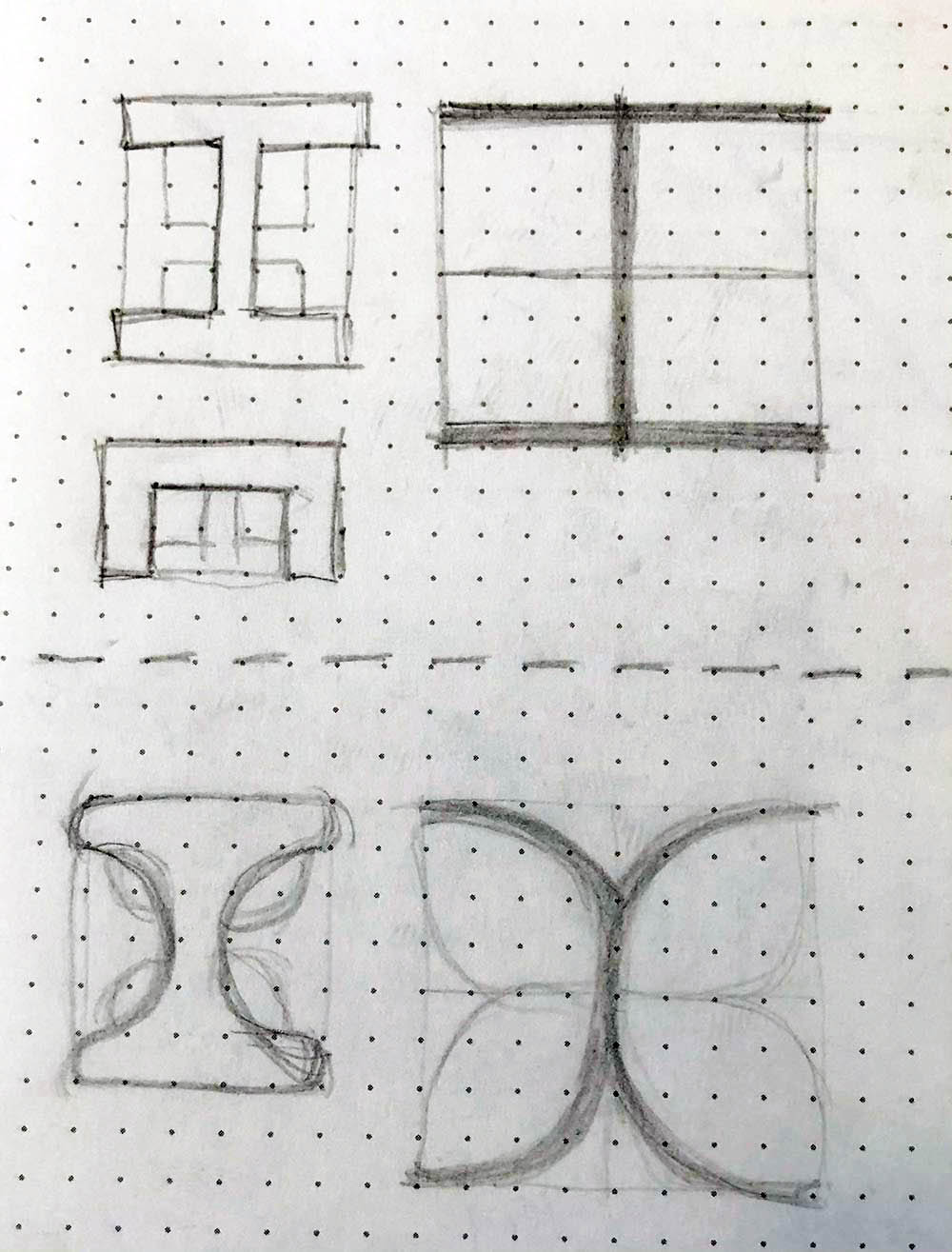
This is a part of the unit.
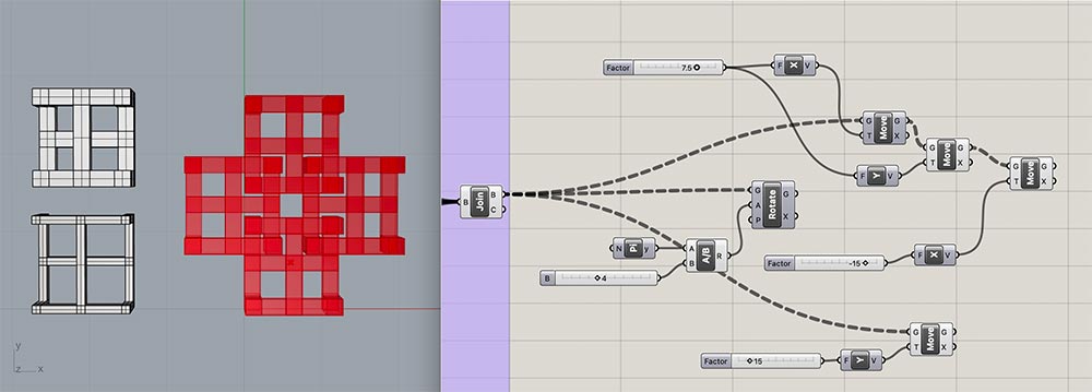
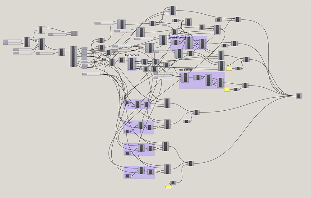
Here is the full Grasshopper script.
And after 3D printing.
Next, I started detailing potential connections between the materials.
Wildcard Week (week 15)
During wildcard week I experimented with various (bio)materials and materials systems. In particular the gelatin-glycerine recipe worked well, so I decided to incorporate this in the final design. This strongly informed the overall design of the wearable, which I also made in Rhino this week.
Applications and Implications (week 16)
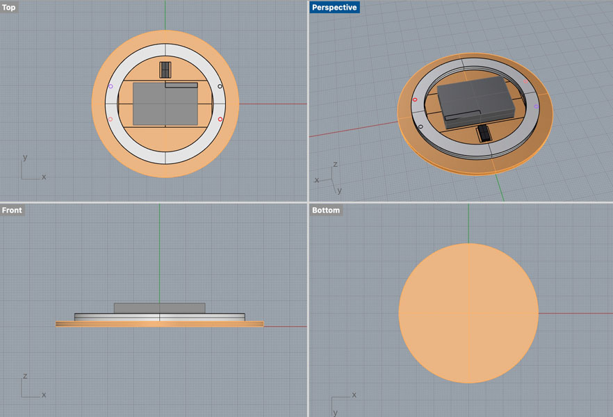
During this week we started to think about the next steps of this final project beyond Fab Academy. The documentation can be found here. After completing this assignment my primary focus shifted to designing the PCB. In Rhino, I started with a 3D model to estimate the sizes of the components and prepare for system integration.
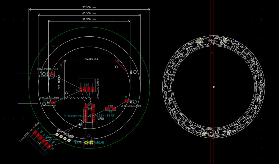
The first version of the PCB was circular. I added vias for the Neopixel ring pins to be pressed into.
To make sure the vias would be positioned in exactly the right spot I downloaded the Eagle model of the Neopixel ring, opened it in Eagle and exported it as .dxf (left image). Then I imported it in Kicad. Next, I cleared up the circles and only kept the information that was needed: the outlines and the positions of the pins.
![]()
![]()
During the design process. I always work with dimensions to make sure everyting fits. Because I wanted to create traces in between the Neopixel pins and the microcontroller, I added 01x01 male connectors to represent the holes. In the final design, I replaced these for vias.
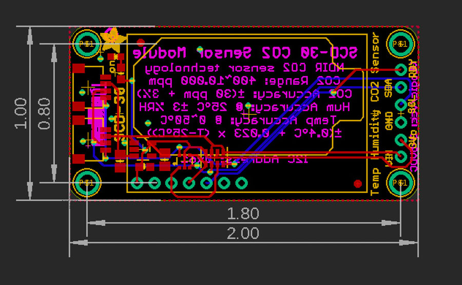
For the sensor, I did the same. Opening the file in Eagle and export as dxf.
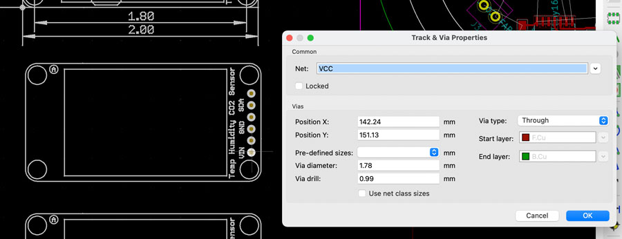
Importing the dxf in Kicad and clearing up all the lines that were not needed. Next, I added vias on top of the holes and connected them to the corresponding nets. Below you can see an example of the one for VCC.
Final design files of the first PCB: traces, outline and holes.
I was not satisfied with this design and decided to remake it. The design process of the Antarctica board was already presented on this page.
During this week I also completed the pattern in Clo, below you can see a screenshot of how I added the Neopixel placeholders.
![]()
![]()
When exporting the pattern to Rhino, I quickly learned that dxf created really messy files. Exporting as pdf was fine though so I proceeded forward with the latter.
![]()
Two curves are created, which is fine.
![]()
Invention, IP and Business Models (week 17)
The documentation of this week can be found here. I also included the licence below on this page. During this week I spent three days getting the fishnet structure to work. Initially, I was planning to go for a much more complex design. In this section I will show the design iterations and all the stuff that didn’t make it into the final project.
Design 1: Grasshopper
Here is the render of the the design I actually wanted to create for my final project. I added a blue background for better visibility. With the fishnet structure being spiral 1, this is spiral 2. As you can see it succeeded to design this, however the calculations were very heavy on my computer. Everytime I made a small adjustment, I had to wait for a very long time.
This is the design in Rhino. I created this in combination with a Grasshopper script that relied on the Weaverbird plugin. This workflow creates solid objects that can be meshed into 3D-printable structures. Rhino is notable for creating solid-like geometries that are very unsuitable for stl files. More on that later.
Based off of this main design, I had to subdivide the shape into three in order for it to fit on the 3D printer’s build plate.
The first succeeded, and printing time was ‘only’ 2.5 hours for such a complex geometry. I was very excited.
However, when I attempted to split the other objects (with about seven different commands, including BooleanSplit, MeshSplit, MeshRepair, Weld etc) I kept getting errors or the calculations crashed Rhino. It was not possible to slice the object and when it would it wasn’t possible to fix the mesh as it created ‘Naked Edges’ and ‘Non-Manifold Edges’. There were thousands of them and it was impossible to fix them by hand (I tried it for about two hours and gave up after that).
With the deadline in mind, this is one of those situations where you have to give up on your aspirations and excercise the triage that Neil talked about in lecture. I was disappointed but quickly moved on to another strategy. Back to the fishnet of spiral 1.
Design 2: Creating my own fishnet in Rhino
Inspired by this Rhino paneling tools tutorial I decided to create my own fishnet. I also consulted the McNeel Paneling Tools Guide.
A summary of the pt commands:
- ptGridSurfaceDomainNumber
- ptPanel2DGrid
Point Attractors can be created with:
- Rectangular surface
- Rebuild
-
SoftEditSrf
- Create point on top of the surface
- ptGridSurfaceDomainVariable
- draw a rectangle
- ptPanelGridCustom
- extrude
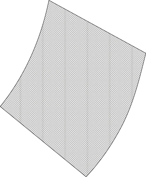
I started with a small test. In Rhino I created a small pattern and applied the above commands. Test piece: rhino ptGrid of approximately 25 x 25 mm. Then I extruded the curves as a solid (0.4 mm). Export as STL. This worked!
![]()
So the next step was to open the pattern and apply the paneling grid commands to it. I started with a grid of 60 x 60 points. My computer had a hard time calculating this.
![]()
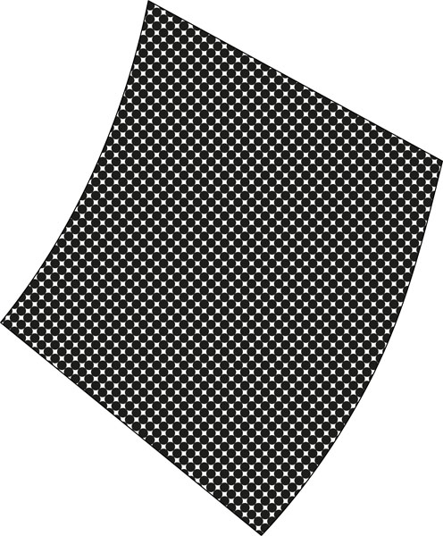
The lines were too far away from each other to create a fishnet, so I doubled the amount of points. It took a very long time to compute.
![]()
This is a close-up of the grid when I applied the ptPanelGrid in diamond shape.
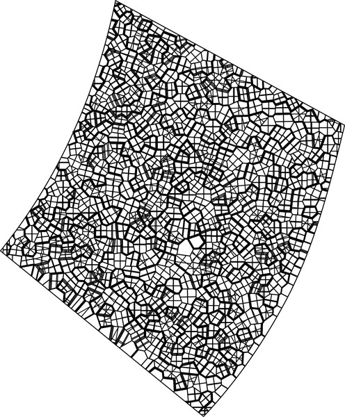
![]()
This is after the calculation completed. I created surfaces and extruded them into solids so they would become 3D printable. Export as stl.
![]()
When I imported a small test piece in Cura I received the following error: “Your model is not manifold.” In this article it is explained what happens and how to solve it. I spent hours trying to fix the model but everyting failed. When I attempted to mesh and export the larger structure, the calculations were too big so my laptop and desktop computer couldn’t compute it. Cura crashed many times, even with the small model. After many attempts I decided that this was a dead road.
Design 3: Back to the fishnet svg
This is the SVG file I worked with during wildcard week. The plan was to apply this simple texture to the pattern.
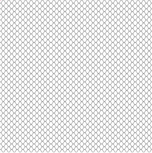
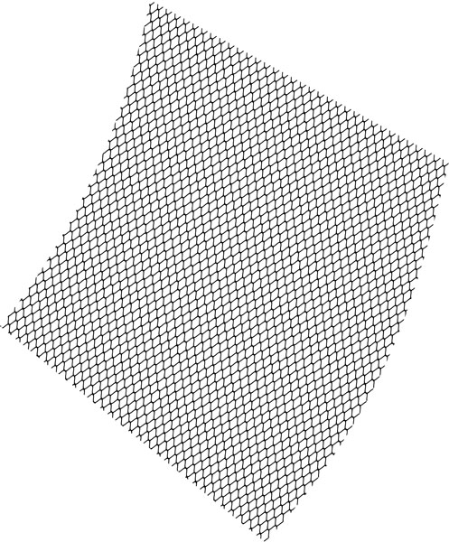
With this I applied the shape to the exterior, but this warped the design. This method is not scalable and creates ugly files.
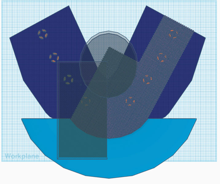
Design 4: Tinkercad hack
Then I continued with my Tinkercad hack that I found during wildcard week. It is kind of the last resort because it’s an ugly process. In Rhino I created a surface of the front with the Neopixels and exported this as an stl file. This file was imported in Tinkercad (blue shape). Then I added the fishnet svg and duplicated this to fit on the pattern.
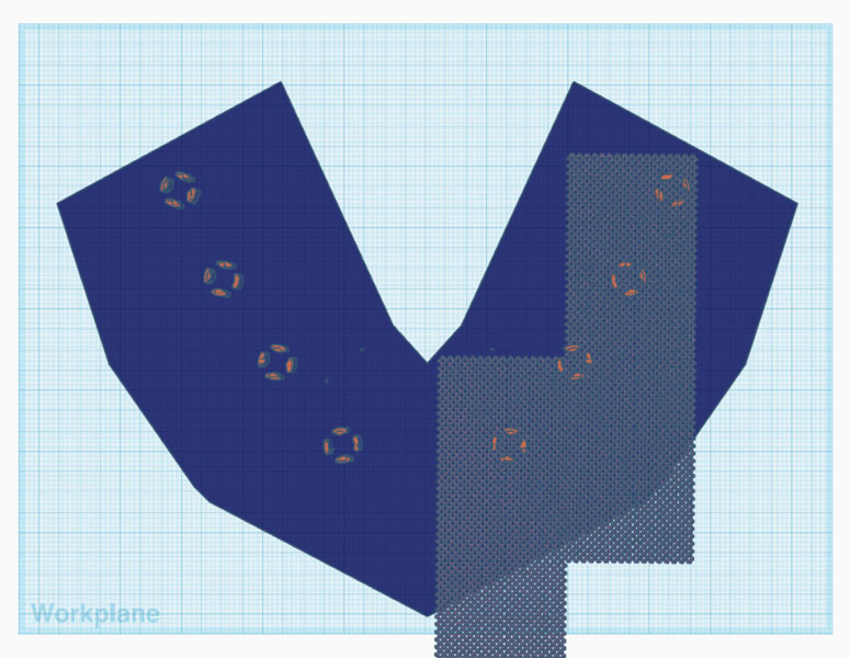
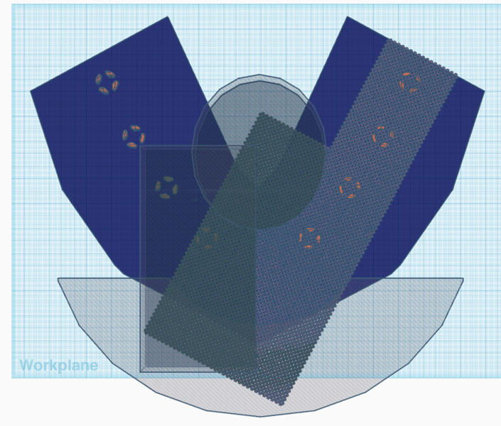
In Tinkercad you can only trim shapes with other objects. I spent a lot of time creating this.
And when I finally had everything ready… This message came.
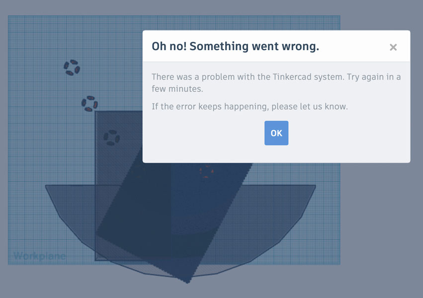
This was an absolute nightmare. It turns out that this method works for a small test sample like I created during wildcard week, but is not scalable at all when you want work with other geometries.
Design 5: Rhino + Illustrator
Designs in Rhino. The middle is a mesh that failed. The right is a Grasshopper script for creating voronoi surfaces.
Experimentation in Illustrator with 2D patterns (left and center) and with importing the voronoi image from Rhino. Neither of the techniques resulted in a successful stl file.
Design 6: Rhino perforations in solids
Next, I tried to create a solid, and make holes in it with ArrayHole. This worked in a small test, but not when scaling up. This is a boring geometry and it turned out that it also was super difficult to compute. Rhino crashed when I applied this method to the pattern.
![]()
Design 7: Grasshopper script for weaving
Based off an example I created another weaving structure. Printing time would be way too long with this geometry so I decided not to move forward with this technique.
Design 8: Grasshopper script for fishnet
Finally, I succeeded with the procedure that was documented above.
Next steps
In the section below, next steps are defined for project development, evaluation and the licence.
Licence
During the week on Invention, IP and Business Models we selected a licence. Because the aim of this final project is to create awareness about indoor air quality, I want it to be widely shared. And I’m planning to put some of my design files up on Thingiverse, for others to download and remix. However, attribution is important. Therefore I selected the Attribution-NonCommercial-ShareAlike 4.0 International (CC BY-NC-SA 4.0) license.
Project Development
The questions related to project development are answered below.
What tasks have been completed, and what tasks remain?
A day before the final presentation I dropped the PCB and it broke the sensor.. What remained was the assembly of the final electronics board, with the new sensor. I completed this a couple of days after the presentation.
What has worked? What hasn’t?
The fishnet patterns as documented above! I had a lot of trouble getting the Rhino model of the fishnet ready for 3D printing. It turned out that the ‘hack’ I found during wildcard week didn’t scale up to the larger structure. The fishnet wouldn’t print when the connectors were designed properly according to Rhino’s rules. In the end, I was happy to have solved it but it was a very tough challenge. Luckily the 8th attempt worked :)
The kombucha sheet failed tremendously. It got moldy after one week. Luckily the gelatin-glycerin recipe provided a back-up solution.
What questions need to be resolved?
After Fab Academy I’m planning to continue with designing bio-based products. The gelatin-glycerin recipe generates predictable results with relatively low shrinkage. However, in future projects I’m aiming for fully plant-based materials. That will pose more questions, for example about material properties: how does it deform after drying and how does it respond to heat and water?
Other questions I’d like to dive into after Fab Academy:
- It would be helpful to have a button on the board, to turn on/off the device when it runs on battery.
- It is a very delicate construction. I’m not very happy with how the wires of the Neopixels on the front are connected to the PCB.
- Will the bioplastics melt when the battery is on?
What will happen when?
During the week after the final presentation I was able to demonstrate the functionality of the full wearable.
What have you learned?
During Fab Academy, I have learned so much! I was particularly new to electronics and programming. This opens up doors to so many more possiblities for personal expression and professional goals. With this newly obtained knowledge I’m starting to understand technological development on a whole new level and I’m empowered to shape it. I have also learned to let go of perfectionism due to the concept of spiral development. Integrating this in my daily workflow will pay back the tuition fee for the rest of my life! This was quite an unexpected take-away, however an interesting one.
Evaluation
During the week on Applications and Implications we were asked how our final project should be evaluated. And how to know if it succeeds or fails. Below are the answers to the evaluation points I wrote down earlier.
First, the electronics can be evaluated by its technical functionality: if the sensor works and if the NeoPixels respond accordingly to changing indoor CO2 levels.
Result: I dropped the CO2 sensor a day before the final presentation. Therefore, the technical functionality of the full wearable could not be shown yet. However, during Output Devices I demonstrated the technical functionality and working code. I fixed the board after the final presentation and made it work.
The same applies to the evaluation of the pattern design and the fabrics production. Is it finished and does it fit?
Result: Using a variety of tools - Rhino, Grasshopper, Clo3D - I was able to produce a pattern, design its texture and manufacture it. The biomaterials production succeeded and it was integrated well with the 3D printed scaffolding structure. It fits the mannequin, and I tried it on as well.
Regarding the wearable’s aesthetics, it is not intended to be a product that will be mass-produced, rather it is an artistic expression to create awareness. How do you evaluate art? That’s an intuitive process based on subjective impressions. But of course I want to make something that looks good!
Result: there have been really cool aha moments from people who’ve seen the wearable or heared about it. So far everyone wants to have it! :) I’m quite happy about the aesthetics too, plus it is exciting to know that there are more spirals to pursue after Fab Academy.
Downloads
Pattern design:
- Clo file pattern (pdf)
- Rhino file pattern (zip, 38.2 MB)
- Grasshopper script (gh)
- Airable pattern front-left (zip, 36.4 MB)
- Airable pattern front-center (zip, 47.8 MB)
- Airable pattern front-right (zip, 36.7 MB)
- Airable pattern back-left (zip, 37.8 MB)
- Airable pattern back-right (zip, 46.5 MB)
Shoulder pads:
PCB design:
- Antarctica board Traces (png)
- Antarctica board Outline (png)
- Antarctica board Through-Holes (png)
- KiCad folder Antarctica board (zip)
- 3D printed bolts and nuts (dxf)
Programming: