Week 15 Wildcard Week
It's wildcard week! In the summary below, you can jump directly to topics.
Summary
This wildcard week is an opportunity for Fab Academy students to explore topics not covered by the curriculum, including soft robotics, biomaterials, textiles and other types of machines. This week was originally dedicated to composites. My focus will be on textiles and biomaterials, because they are an important element in my Final Project.
Assignments
Design and produce something with a digital fabrication process (incorporating computer-aided design and manufacturing) not covered in another assignment, documenting the requirements that your assignment meets, and including everything necessary to reproduce it. Possibilities include but are not limited to wildcard week examples.
Learning outcomes:
- Demonstrate workflows used in the chosen process
- Select and apply suitable materials and processes to do your assignment.
Project management
This week’s planning:
| Spiral | Tasks | Time |
|---|---|---|
| 1 | Group assignment | 2 hours |
| 2 | Bio-based material production | 16 hours |
| 3 | Designing CAD files | 16 hours |
| 4 | Laser cutting and 3D printing | 16 hours |
| 5 | Documentation | 8 hours |
Let’s get started!
This week’s results
Biomaterial production:
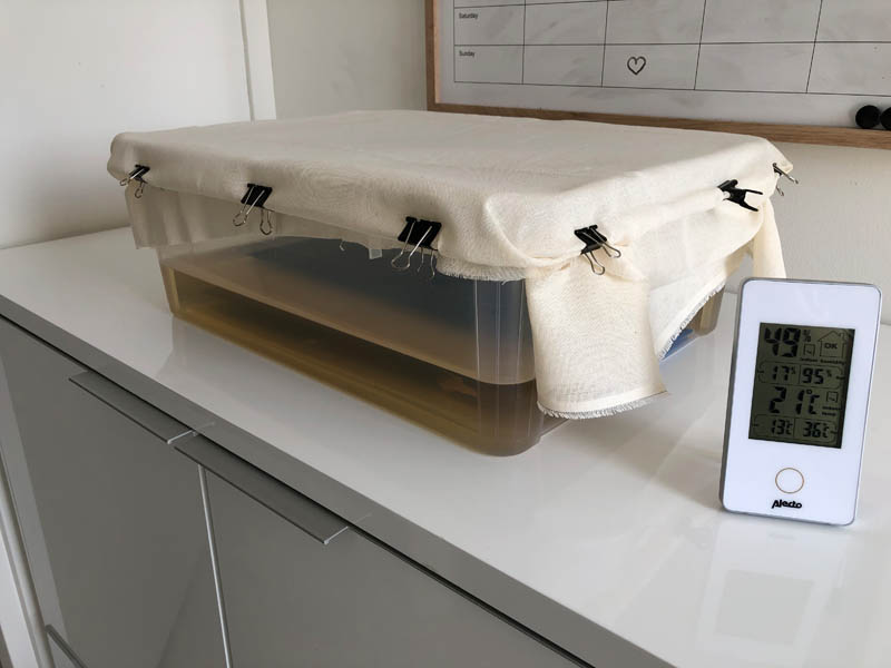
Kombucha growing process:
Fishnet svg printing:
3D printing textile-like material:
3D printing on fabric:
Group assignment
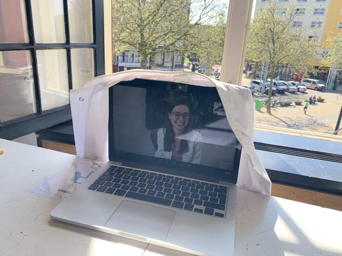
This week I attended the group assignment from home to reduce exposure to hazardous materials.
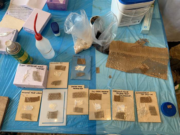
For the group assignment we worked with Tarbender. The safety data sheet provides insight in the hazardous materials and how to handle them. The following ingredients are hazardous according to Regulation 2012 OSHA Hazard Communication Standard: Oxirane, 2,2’-((1-methylethylidene)bis(4,1- phenyleneoxymethylene))bis-, homopolymer. Picture by Paula.
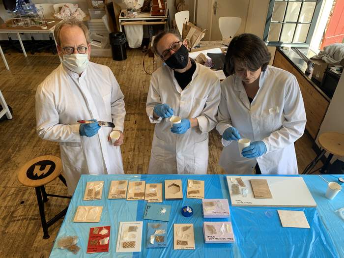
So nice, they also gave me a lab coat :)
Here is a video by Smooth-On on how to make a bartop using Tarbender. The group made many samples at Waag. Picture of the results by Paula:
Intro to biomaterials
Inspiration from Fabricademy students:
Binders
- Agar
- Gelatin
Natural gums can be categorized according to their sources and chemical structures. (a) Marine (sea weeds) origin: agar, alginate, carrageenan; (b) microbial origin (fungi, bacteria, algae): pullulan, glycan, dextran, gellan gum, dextran; and (c) plant origin: (i) seed gums (e.g., guar gum, locust bean gum, starch, amylase, cellulose); (ii) tree exudates: gum arabia, gum tragacanth, ghatti gum, karaya gum; (iii) tubers-Potato starch (e.g., Konjac); and (iv) extracts-pectin.
Gelatin: Is it a waste product or does it create value as a by-product, thereby incentivizing pig farmers?
Fibers
- Coffee grind
- Functional properties and processing of carrot.
Additives
Bioplastics based on wheat gluten processed by extrusion
The preparation of wheat gluten bioplastics by extrusion was the main objective of this research, modifying their structure by varying the pH value or by incorporating additives (glyoxal or xanthan gum).
To improve water resistance, add beeswax to the bioplastic solution - bioplastic cookbook
Biomaterials production
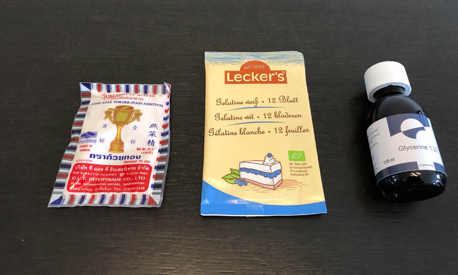
Materials
- Gelatine
- Glycerine
- Agar Agar
- Food coloring
- Xanthan gum
Glycerine calculation
Density of glycerine-water solutions:
- 100% glycerine at 20 degrees celsius = 1.2611 g/cm3
- 86.5% glycerine at 20 degrees celsius = 1.225 g/cm3
So that translates to:
- 1 gram = 1 ml for water
- 1 gram = 1.26 ml for glycerine
These recipes are for reference.
Recipe (cook book):
- Glycerine 3.6 g = 4.536 ml
- Water 60 ml
- Gelatine 12 g
Loes:
- Glycerine 16 g
- Water 480 ml
- Gelatine 96 g
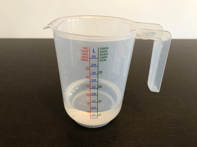
Recipe
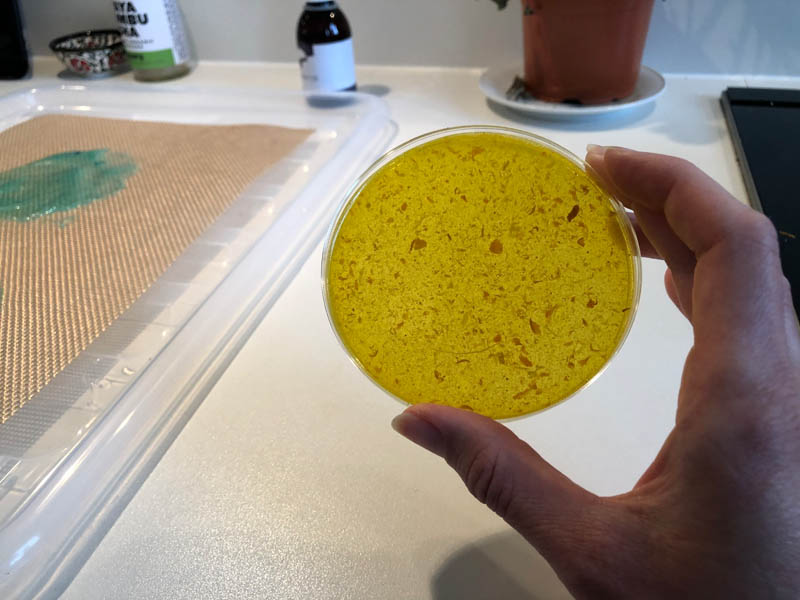
Start: 15:05 uur Simmer and slowly stir the mixture between 60-80 degrees celcius for at least 20 minutes or up to an hour. Turn it lower when bubbles appear: you don’t want the liquid to move, don’t boil it.
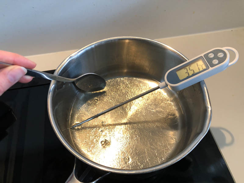
Keep the temperature below 80 degrees celcius while stirring very very slowly and gently to avoid making bubbles. I prefer a simple spoon to do this, not a whisk.
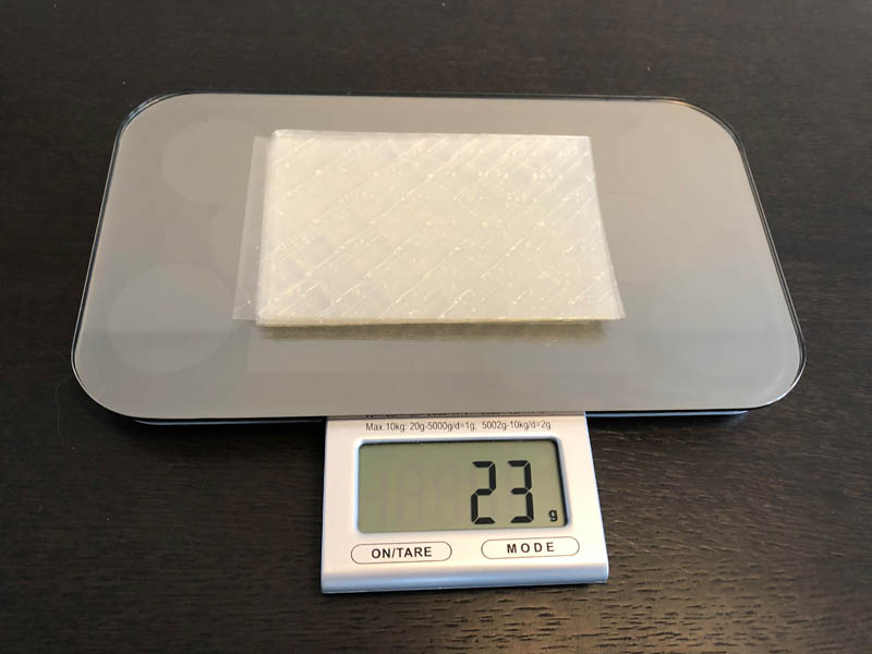
- Gelatine: 23 grams
- Glycerine: 7.2 grams = 9.1 ml
- Water: 120 ml
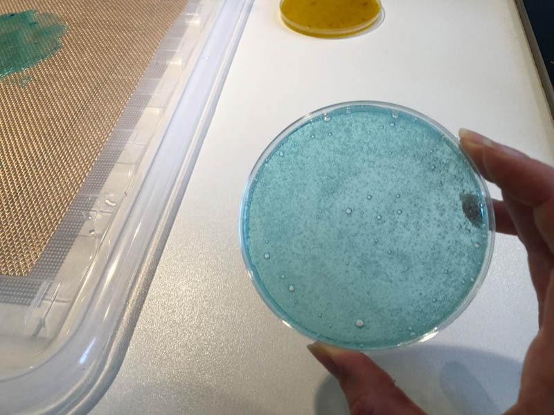
- Blue food coloring
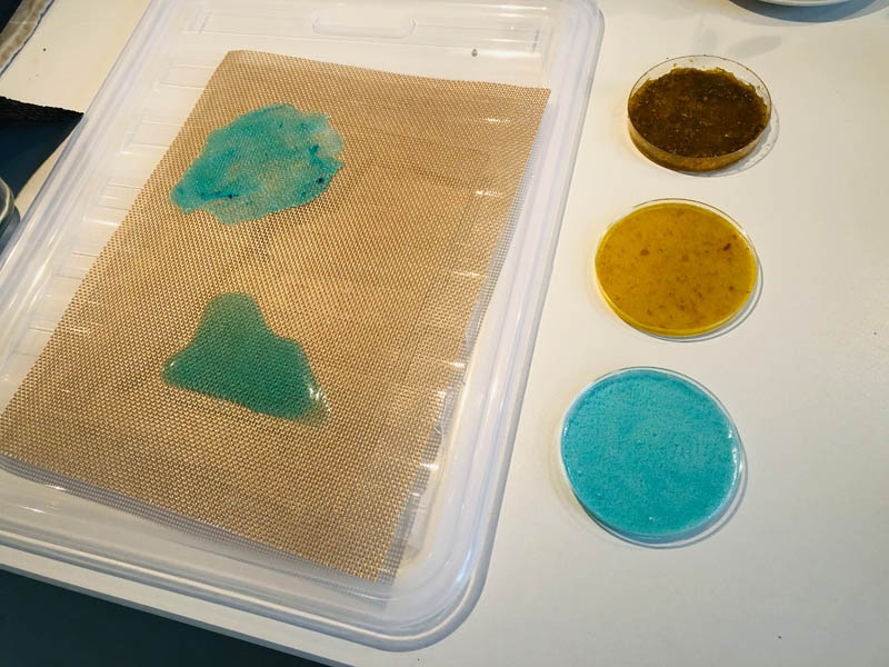
15.36 uur: remove and pour into petri dish.
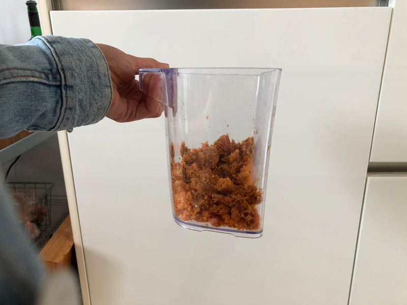
Next, I made a sample with some leftover tumeric, carrot and ginger fibres from a juicer. The right picture is a little bit of fibres + spoon of tumeric powder to make it yellow.
Creating structure can by achieved by pouring the mixture over fabrics, nets and other textured materials.
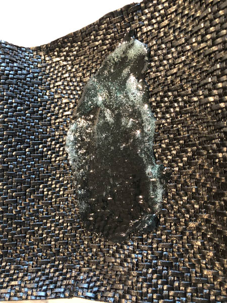
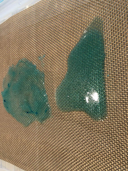
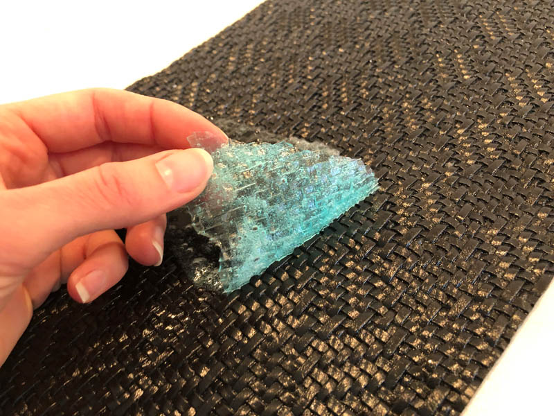
After 1 day of drying you can peel it off the surface:
A summary of the day:
Next, I wanted to experiment a little bit more with two more recipes.
Coffee recipe on Materiom:
- Glycerol 10 grams
- Water 200 ml
- Vinegar 10 ml
- Coffee grounds 10 grams
- Sodium alginate 4 grams
Changed that to a glycerol - mix.
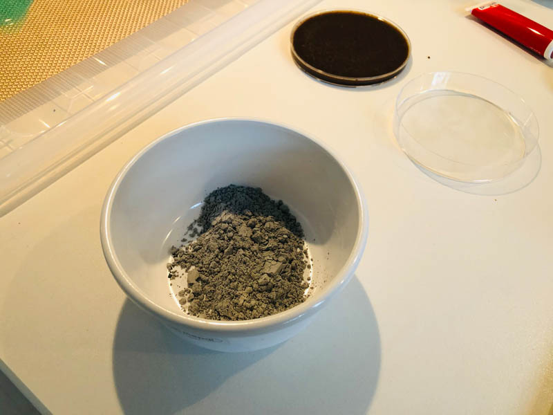
Charcoal Conductive Gelatin bioplastic inspired recipe:
- Gelatin 26 gram
- Glycerol 10 gram
- Water 100 ml
- Activated charcoal 16 gram
30 gram glycerol (liquid)
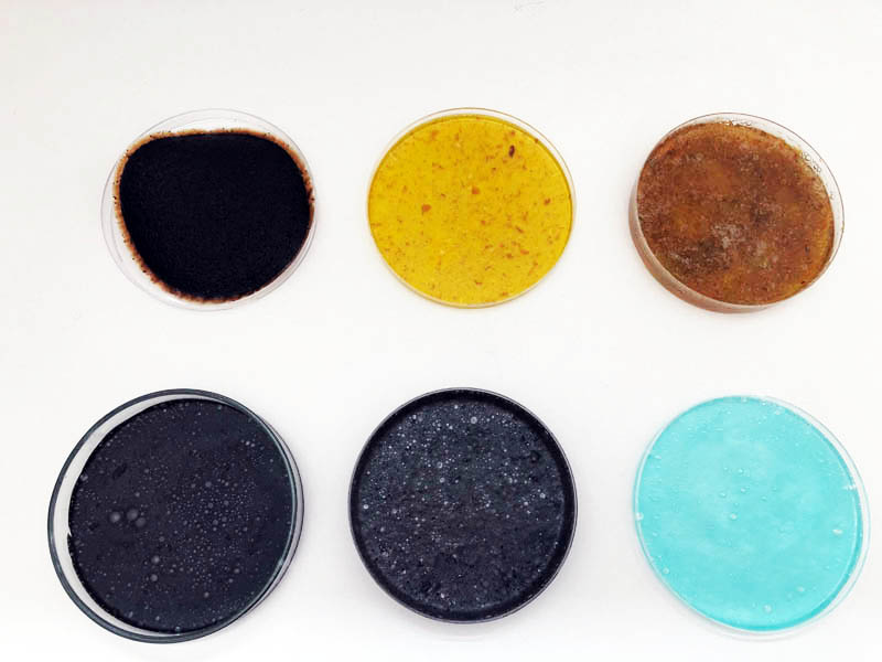
Here are the two samples:
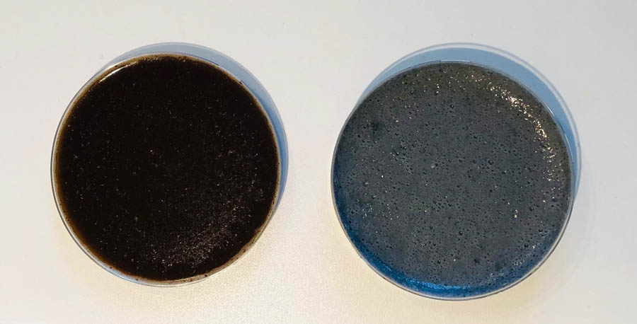
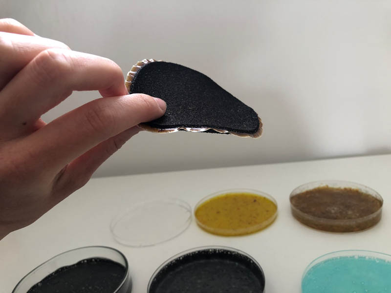
All samples after 1 day of drying:
Here you can see the coffee sample warping.
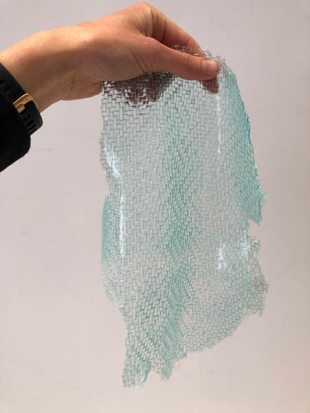
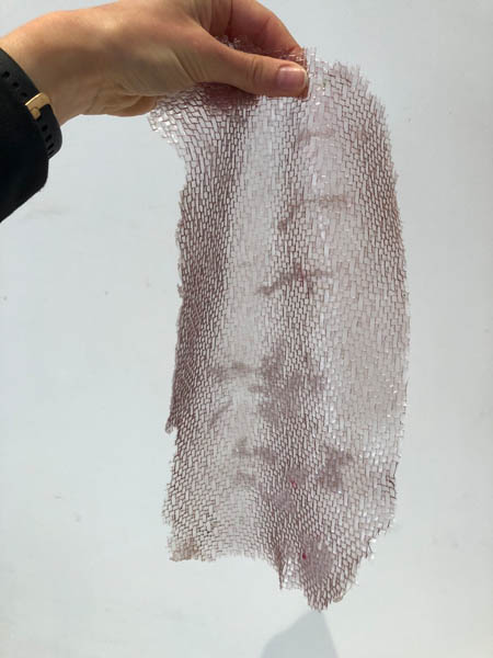
Scaling up the sheets
Gelatine: 40 gr Glycerine: 18 ml Water: 240 ml
Here are the sheets in action:
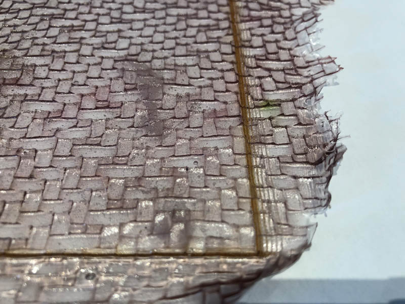
A close-up of the large sheet:
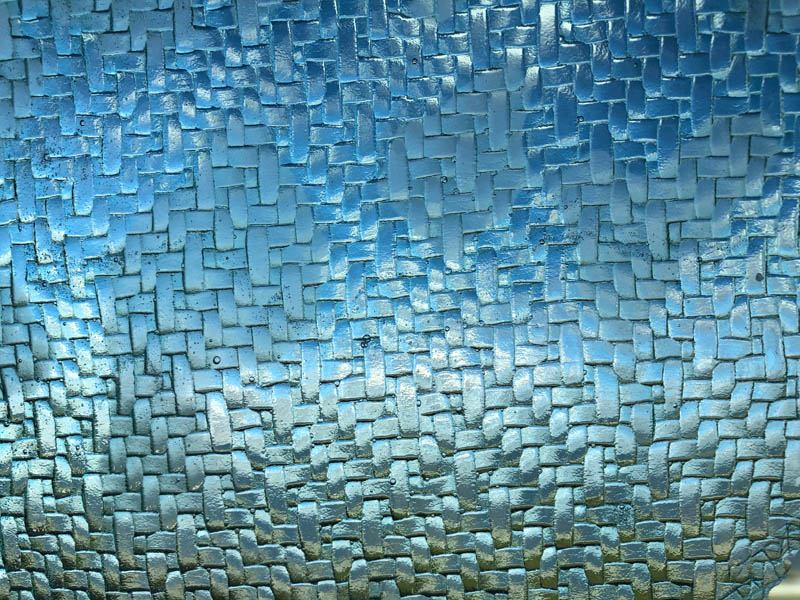
Laser cutting the biomaterial sheets
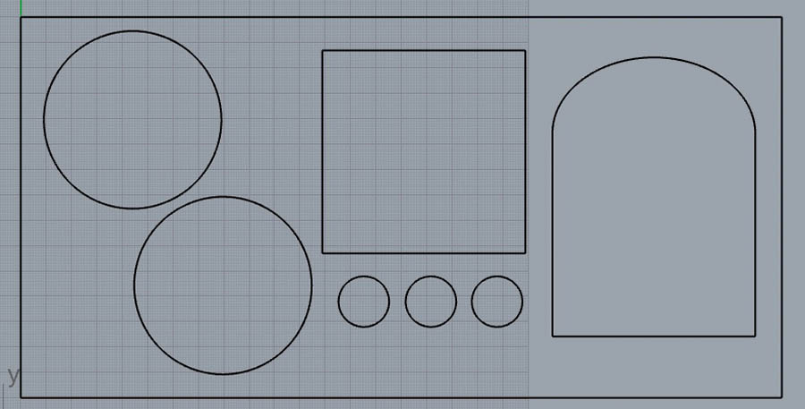
To combine biomaterials production with fabrication techniques, I decided to try laser cutting. The sheet is 150 x 300 mm. Thickness of the sheet: 5 mm. I created the following design in Rhino.
Laser cutting with a variety of settings for speed and power. I started very careful because if you add too much power the sheet will melt. Eventually I cut this with speed 10 and power 100%. This is a lot, and I was surprised that it didn’t cut all the way through.
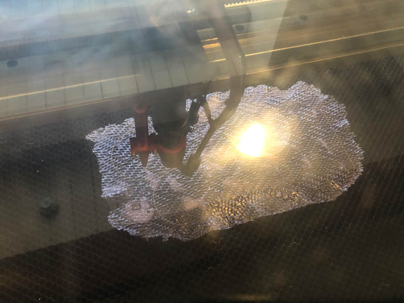
After laser cutting. I had to laser the material many times (8+ times) and it still didn’t come all the way through. Just before I started working with the laser cutter, Henk did some maintenance on this machine. I suspect some settings changed, resulting in a less powerful laser.
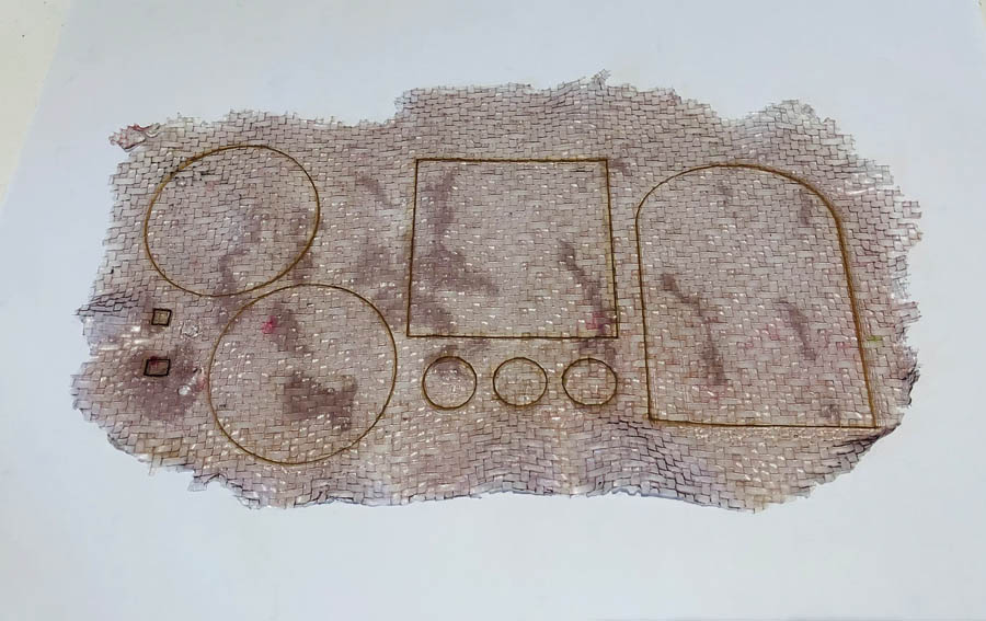
Here you can see how the laser cutter slightly offsets the design in each run. This should not be the case.
Thus, I ended up cutting the material with a knife and scissors. The engraving of the lasercutter provided great guidance.
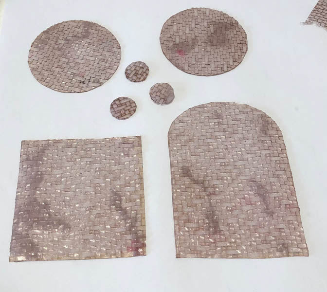
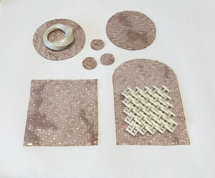
Here it is with the jewelry on top of it.
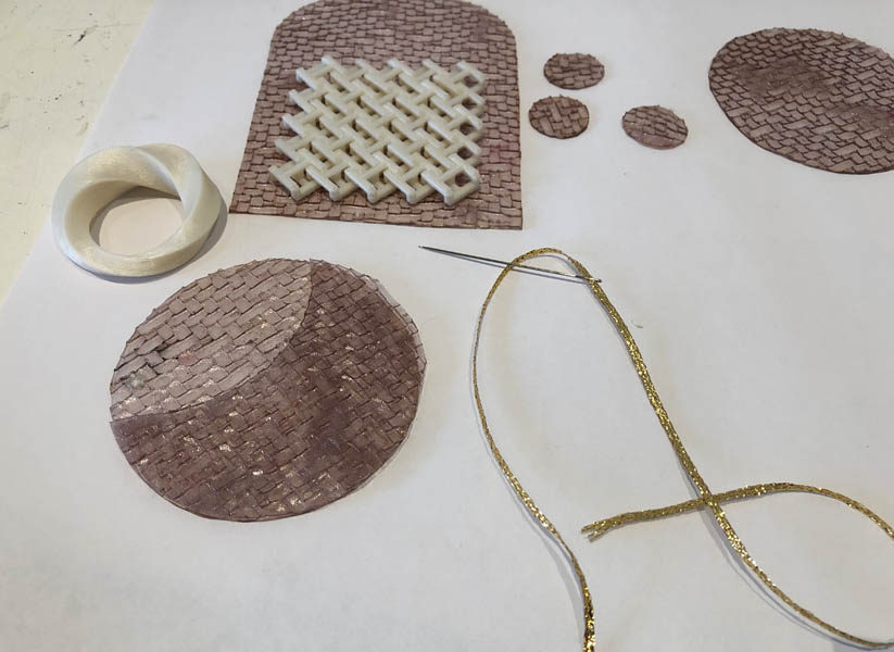
Sewing the parts together with golden thread.
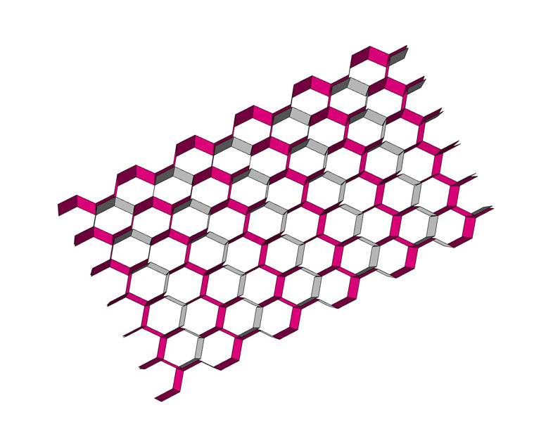
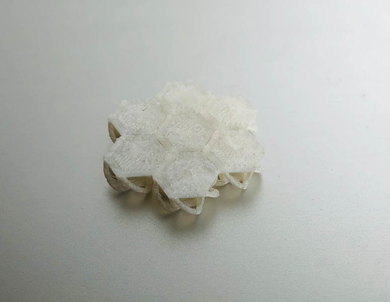
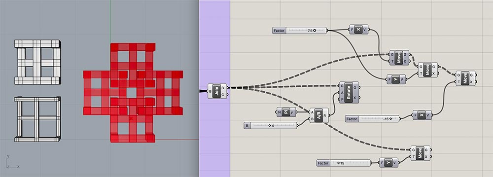
Kirigami
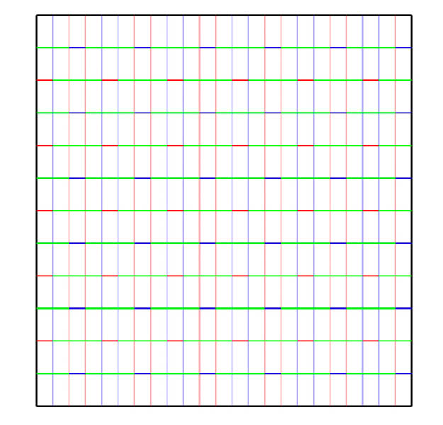
The Origami simulator I experimented with the Kirigami Honeycomb.
- Mountain folds have red stroke - rgb(255, 0, 0), hex #ff0000
- Valley folds have blue stroke - rgb(0, 0, 255), hex #0000ff
- Boundary edges have black stroke - rgb(0, 0, 0), hex #000000 - use this edge type for both the outline of the pattern, and any internal holes.
- Cuts have green stroke - rgb(0, 255, 0), hex #00ff00 - use this edge type to form thin slits in the pattern.
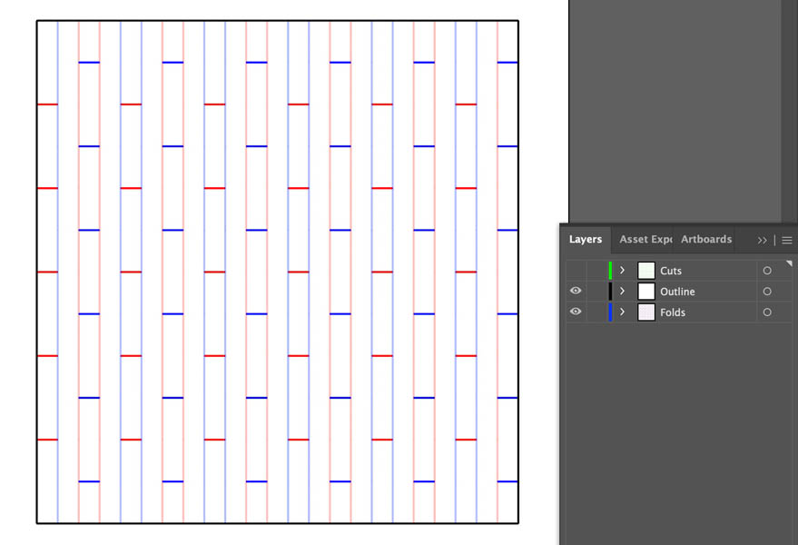
In Illustrator, I sorted the lines in various layers to prepare for laser cutting.
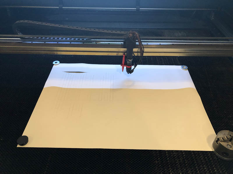
After laser cutting. Unfortunately the laser was not working properly after a maintenance session.
3D printing and fabrics
This week I’m mostly interested in discovering techniques for pattern generation and workflows for translating the digital designs into 3D-printed structures. Therefore, the geometries will be relatively simple. The idea behind this is to get an initial exposure to the methods and evaluate the ones most suitable for the final project. The focus on prototyping techniques over designing one complete design enables a decision-making compass for further expression.
Chainmail
Creating structural geometry with 3D printing can be achieved with a chainmail.
Chainmail version 1:
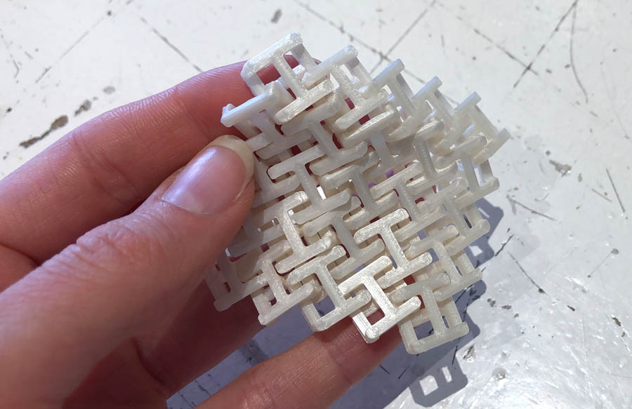
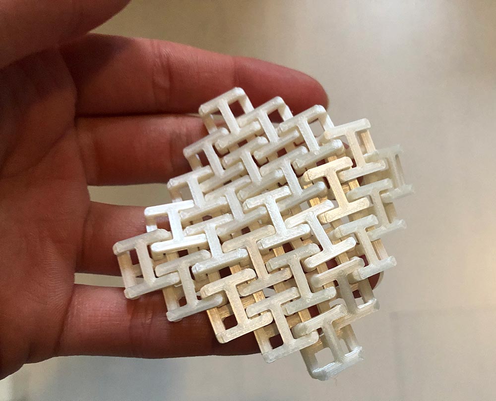
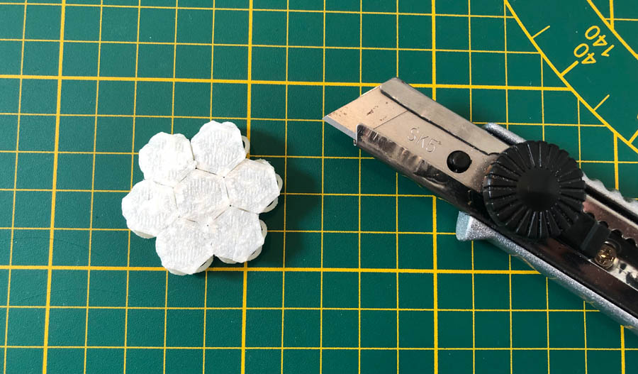
Version 2: Hexagonal chainmail
Printing time: 1 hour printing time for the small design. After printing. The hexagons are connected, where they shouldn’t.
Using a Stanley knife, I cut them off. Unfortunately it was very fragile. You can’t put much pressure on the design.
Here you can see the design in action:
You can only move the design to the inside. No axial movement is possible.
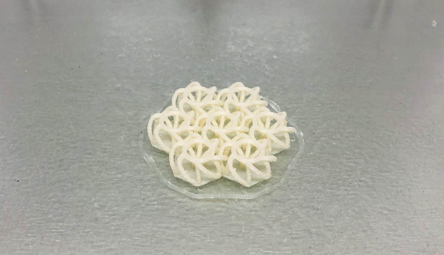
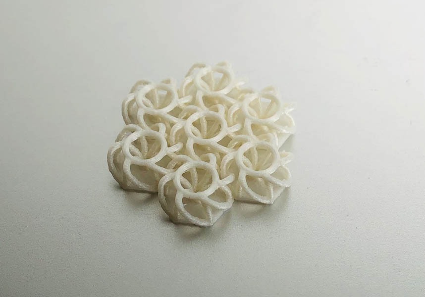
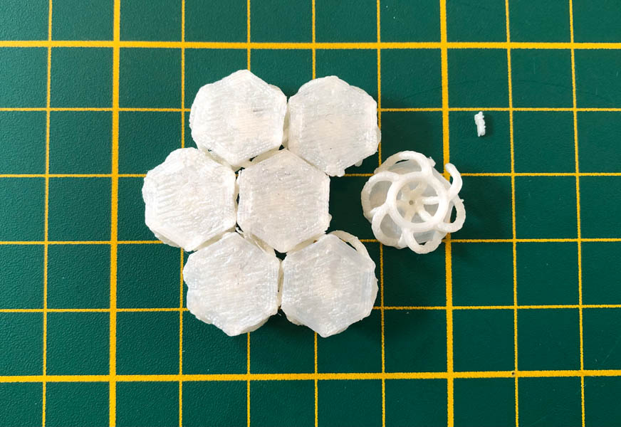
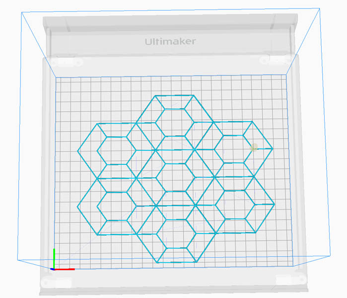
Version 3: my own design. This is a part of the unit.
Here is the full Grasshopper script.
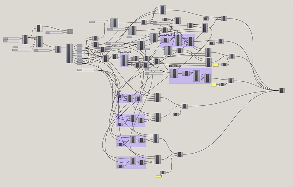
Due to time constraints I wasn’t able to make final tweaks to the design, like adding fillets to the corners.
Fishnet: from SVGs to 3D printing
SVGs are useful for designing and printing 2D patterns and making them into fabric-like materials. Because I wasn’t familiar with this workflow, I was interested in exploring this. Cura has a plugin called SVG Toolpath Reader to 3D print 2D structures. First, I downloaded an SVG image of a fishing net pattern from internet. Then I imported this in Cura. Unfortunately, the software couldn’t process the image.. After a search on the internet, I found that this functionality is not really supported by Ultimaker. :(
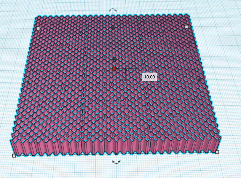
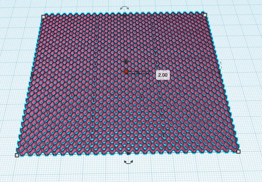
Option 2: Import in TinkerCAD and convert SVG files to STL files. I start with the example fishnet file, which loads successfully. It automatically adds a layer height to the SVG file. I change this from 10 mm to 2 mm.
Because I want to prototype with various settings, I’d like to make this file smaller. Cutting off parts in TinkerCAD is a little counterintuitive. You have to create a box, make it a ‘hole’ instead of a ‘solid’, place it on the part you want to cut. Next, you join both objects.

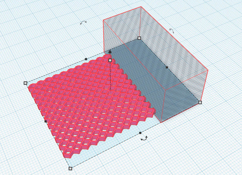
Then you sort of randomly click and rotate on the canvas and the existing object until the hole box disappears.
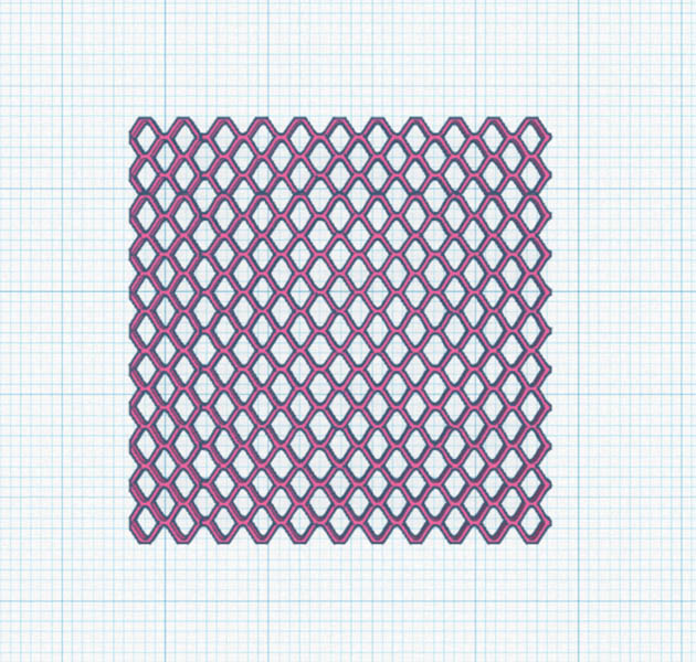
Export as STL and send to Cura software. Printing time is 15 minutes. Changing the layer height to 1mm reduces printing time to 7 minutes. I’ll try that first.
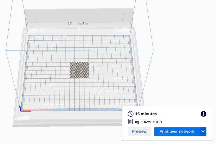
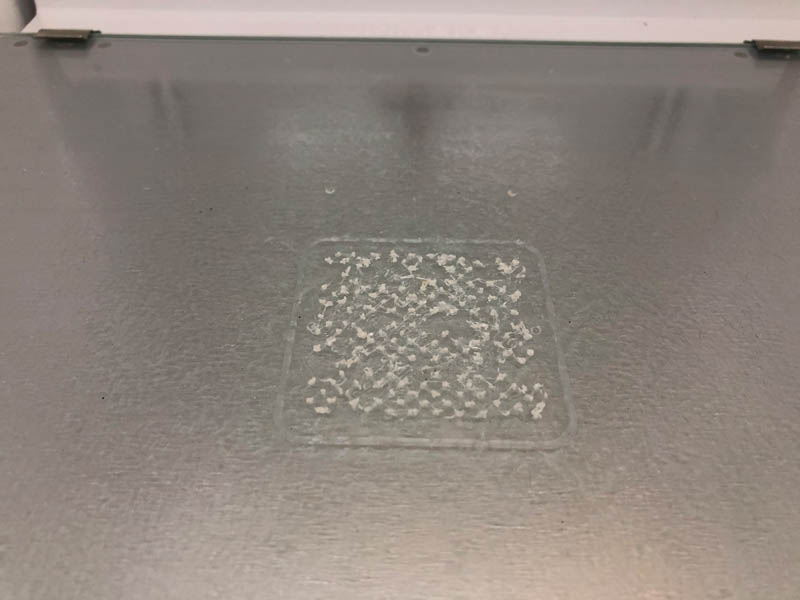
Result: a few dots. Next, I’ll do this again with a layer height of 2mm. Result: a little better, but still not quite there yet. Then I see that I had kept the layer height in Cura on the standard 1.5 mm.
Checking the toolpath in Cura’s simulation tab reveals why this didn’t go quite right.
Setting the Surface Mode in Special Modes to ‘Surface’ seems to be creating a better printing pattern for this type of design.
I set the printing profile to Default and 0.2 mm. And I reduce the printing speed to 20 mm/s and the speed of the initial layer to 10 mm/s. This should improve adhesion to the build plate. Also, because I’m experimenting with the printer settings, I make the file a bit smaller for a quicker prototyping cycle. The printing time of this model is calculated at 3 minutes.
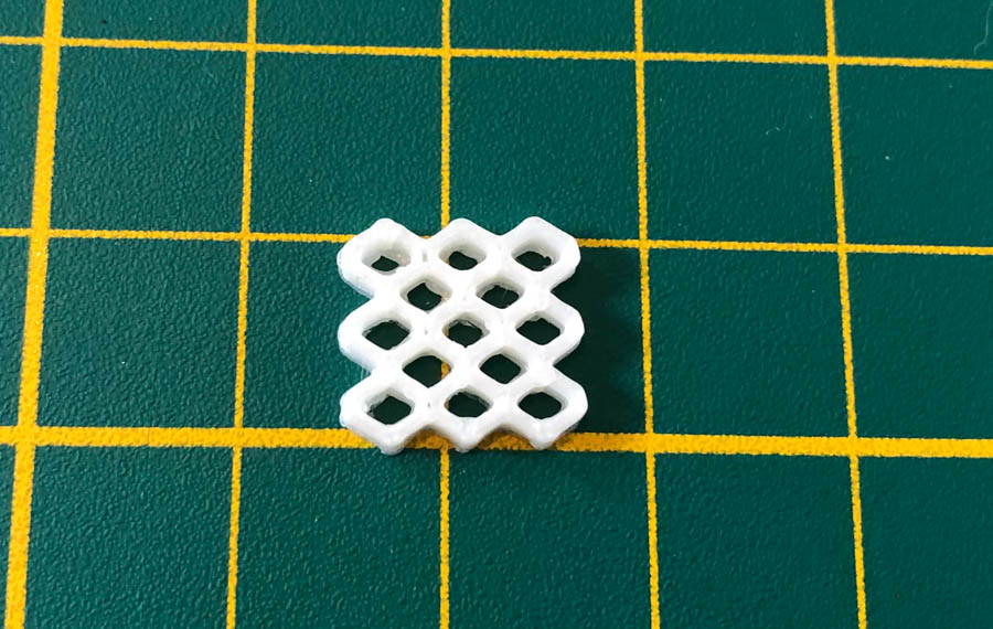
This looks good! Now I print the same design without the speed adjustments. I also disable the brim by setting Build Plate Adhesion Type to None. The printing time is only 1 minute.
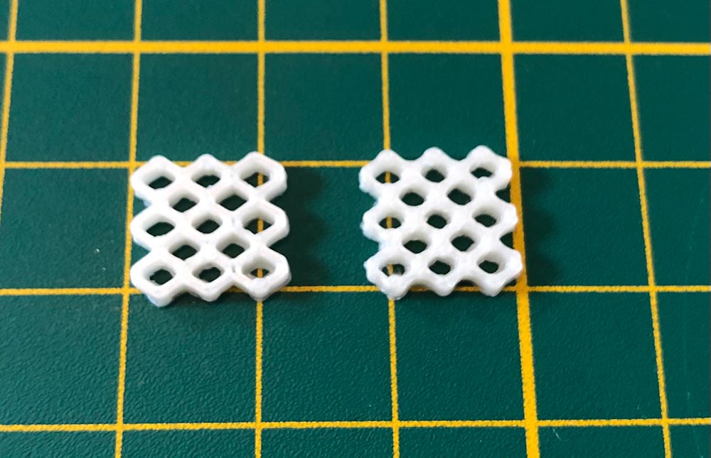
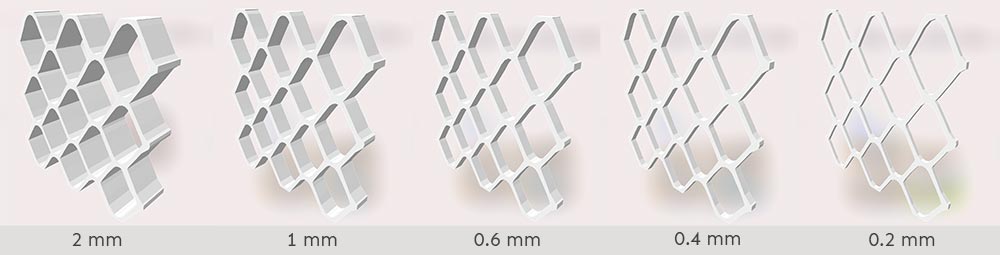
It still looks good, but the first print has more detail. The second print at standard speeds of 70 mm/s and 20 mm/s for the first layers is more ‘smushed’ together. Next, I adjust the same design from Tinkercad with a height of 1 mm and export the STL file to Cura. Then, 0.6 mm. Moving on to 0.4 mm, and 0.2 mm, this is only one layer height. It creates a flexible and very flat structure. Be careful when taking it out of the printing bed.
Then, I experimented with reducing the Line Width in the quality panel from 0.35 to 0.25. This turns the field orange. 0.3 is still ok. I’ll try 0.25 mm. And I also set Infill Line Width to 0.25 mm. By default, the Initial Layer Line Width is set at 120%. I keep this setting for now.
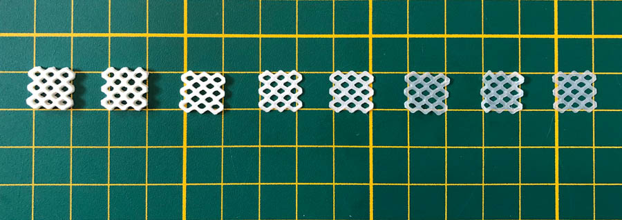
Because I want to create a smaller net, I set the line width to 100% to see what will happen. Cura shows that increasing this could improve bed adhesion. By setting this to 100% I take a risk of reducing this. So far, the designs came out very nicely. So let’s take some risks :) Here is the entire family:
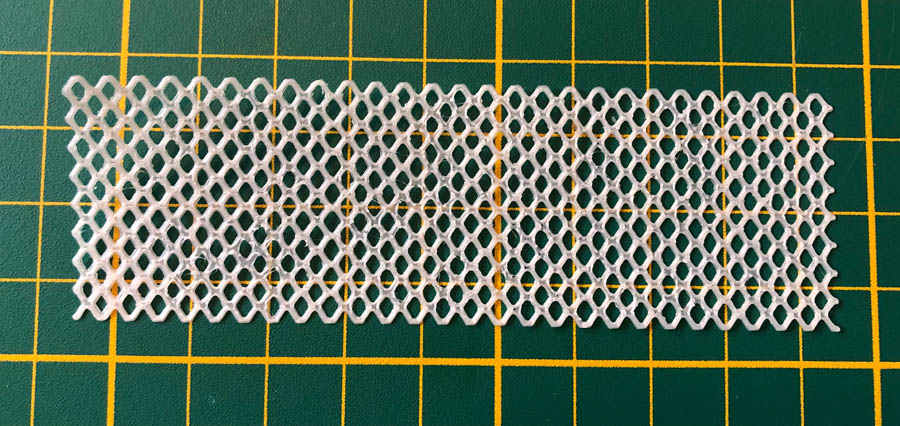
This one actually looks better than the previous! Now let’s print a larger fishnet with these settings. When I took it out of the printer, some parts were sticking to the bed. There was some glue left (from when I still glued the build plate). The parts that weren’t glued came out nicely. It actually is a pretty strong and flexible material, resembling a fabric.
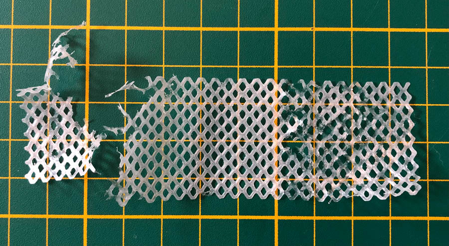
I removed the glue and printed it again with 0.4 mm. The estimated printing time is 17 minutes.
Et voila! Looking wonderful.
Rhino
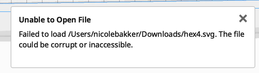
Then, my own Rhino file. After importing the test file to Cura, it shows an error. So then it must be something with the Rhino file. In my opinion, exporting to an SVG in Rhino is a tedious and troublesome process. I looked up svg exporting processes on Youtube, and couldn’t really find a single tutorial. Most people export directly to an .ai Illustrator file if they want to create vector graphics. For example this one:
Interesting side path: making vector lines in Rhino. Make an isometric view and save it as a viewpoint. Type Make2D to create a vector file for Illustrator. In the drawing options pop-up frame, select “Maintain source layers” in object properties. Hit OK. Look at it from top view. Then export as an Illustrator file.
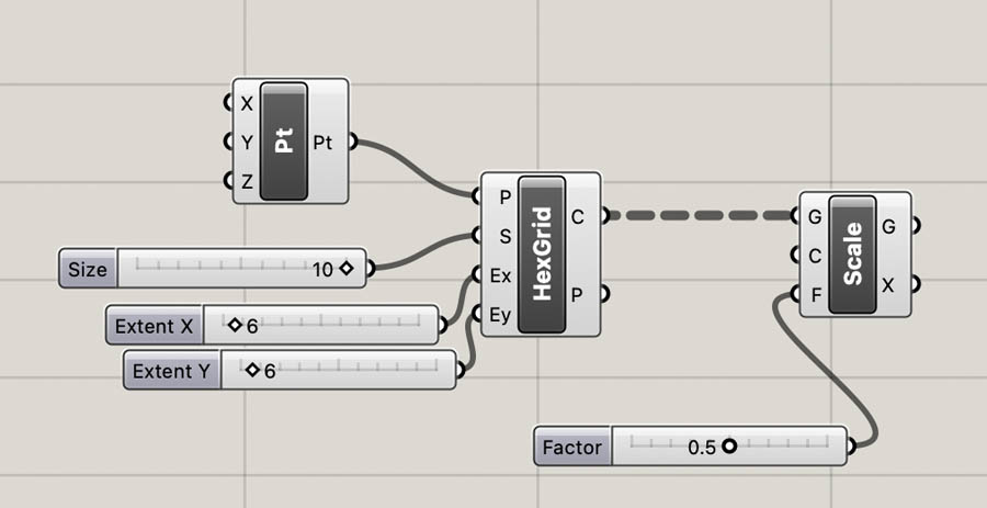
Ok, so let’s move back to my design process of going from Grasshopper to 3D-printable SVG. Here is the Grasshopper script:
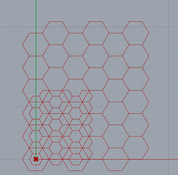
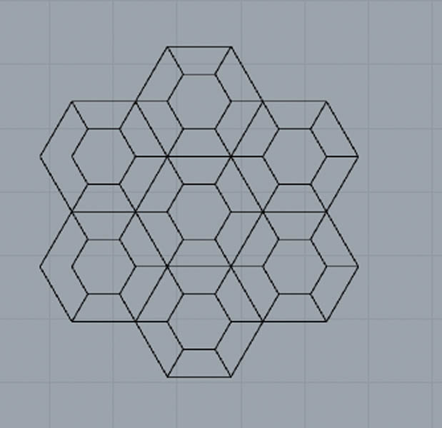
I baked it in Rhino. Then I ungrouped and exploded the both hexagonal grids and deleted the outer lines until this shape remained:
With Export Selected I saved the file as an .svg file with the following settings:
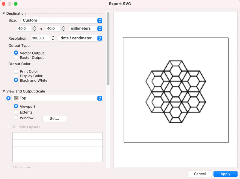
There is this really sneaky setting you have to beware of:
Then export the .svg file and import this in Cura.
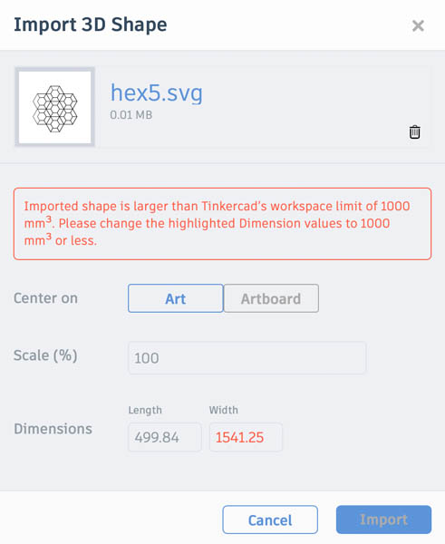
Importing the design into TinkerCAD also results in a major error, revealing a little more about the reason why this doesn’t work.
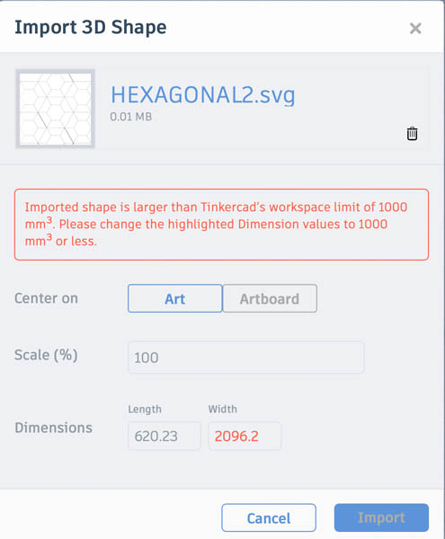
Somehow Rhino creates a way bigger file, despite defining a maximum frame size. Reducing the resolution.
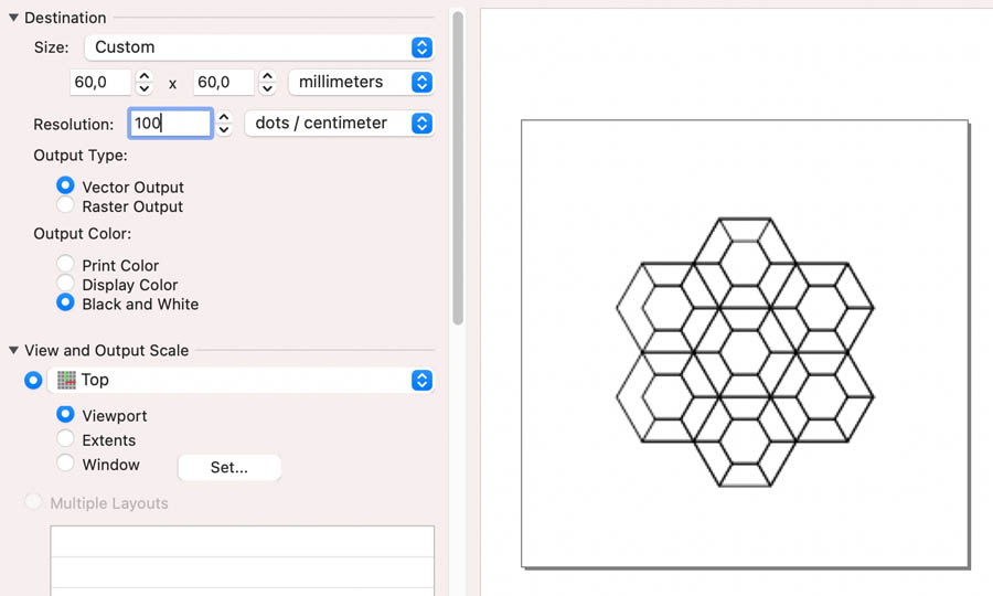
Again, the file’s dimensions change.
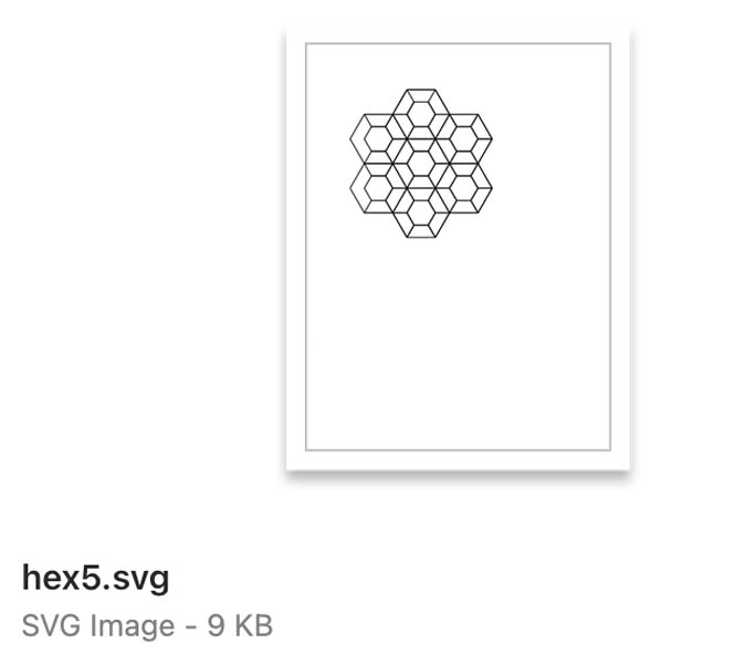
Opening the SVG file shows this. Not exactly the 60 x 60 mm of my export settings.
Then I changed the design in Rhino, by adding height to the file.
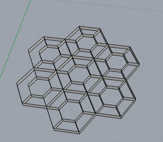
And importing this in Cura shows this:
I give up on exporting SVGs with Rhino!
With Export Selected I saved the file as an .ai file with the following settings:
Then in Illustrator I exported as an SVG.
Conclusion: it is better to design a 2D file in Illustrator and export it as an SVG file there. That is quite unfortunate, because when I create patterns in Grasshopper I’d like to be able to 3D print them.
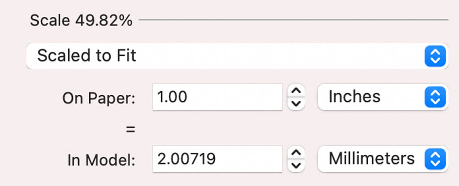
Illustrator Finally, make a design in Illustrator. Just a random shape from the standard toolbox.
I export this and import in Cura. Again: no success. Even a shape of which we know is 40 x 40 mm will translate as a huge file in Cura.
3D print on fabric
Next, Bea showed some beautiful examples from the Fabricademy. For example Loes Bogers. For creating 3d shapes on fabric this is a really helpful guide with multiple examples and this IAAC blogpost.
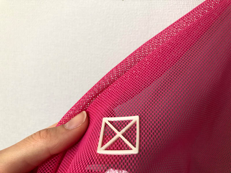
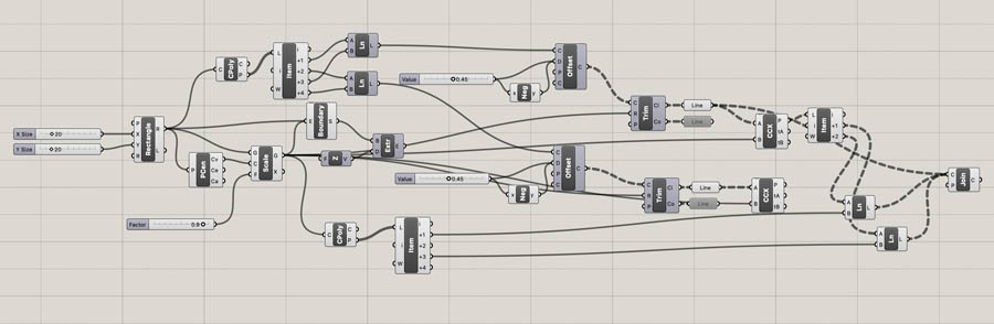
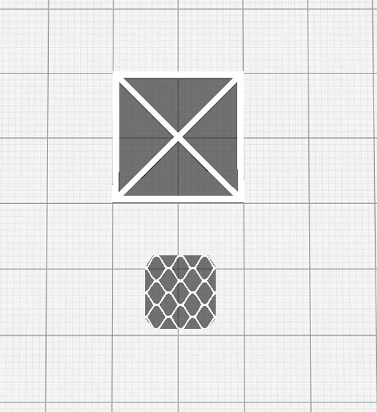
In grasshopper, I created a simple square with a cross.
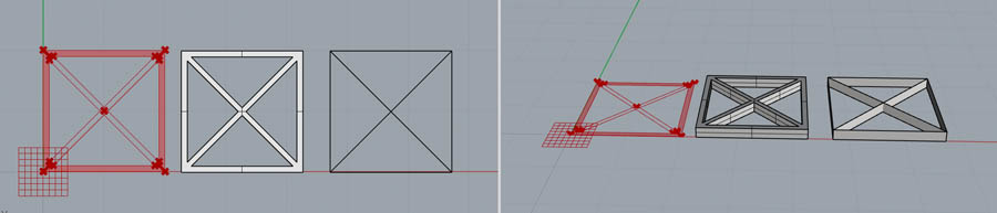
Here is the script:
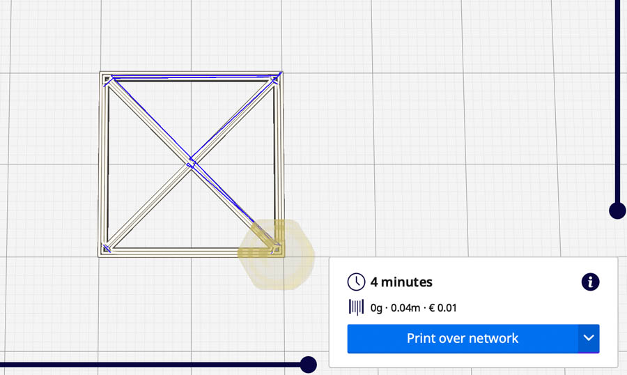
In Cura, I added the Z Offset Setting plugin. But doesn’t work. So I changed the Initial Layer Height from 0.2 to 0.3 mm to prevent the nozzle from dragging the fabric. Printing time is 4 minutes.
Preparation of the printing bed. Duct tape is king!
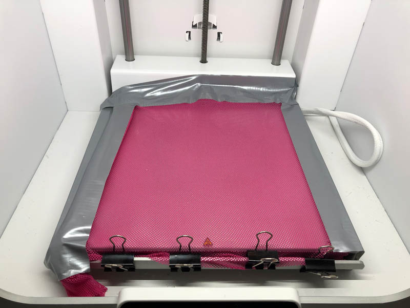
And just when I was about to press ‘Send file to printer’, this happened…
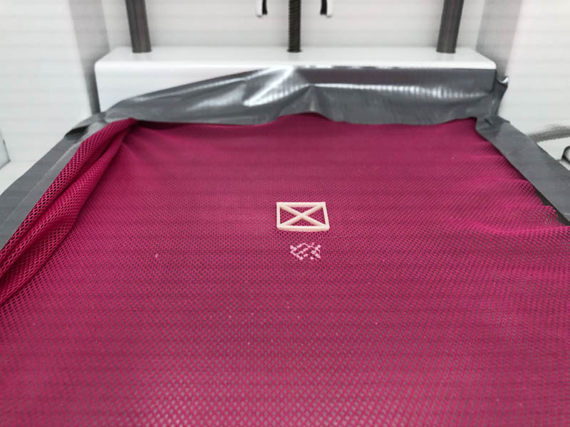
Success!
Next, I wanted to add the fishnet.
After printing.. This didn’t really work out.
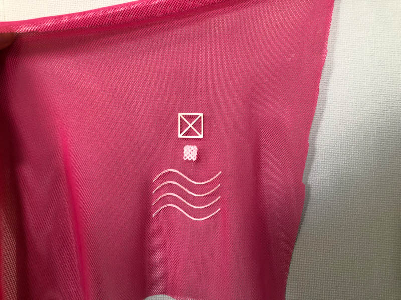
I also created a wavy pattern in Rhino.
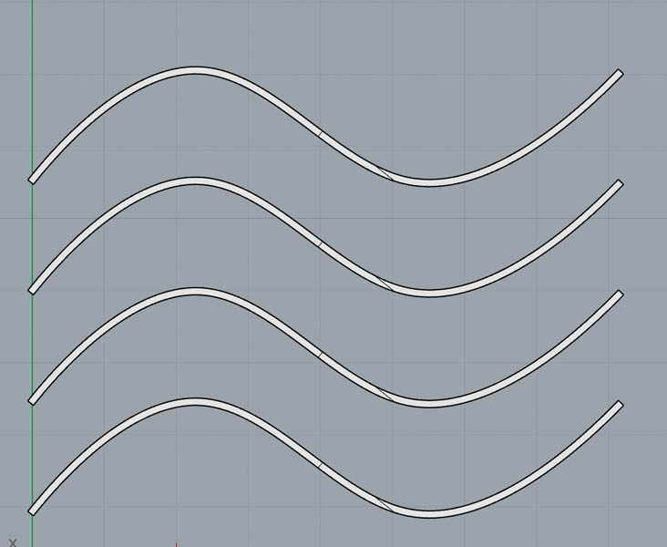
In Cura, I scaled down the model with 70%. Still had Surface Mode on. Should be turned to Normal for this wavy pattern. Here you see how it’s printed nicely on fabric:
Pattern creation on surface in Rhino
How to create a pattern on a vase design in Rhino. Here are the steps:
- Work with the
UV Curvecommand in Rhino to lay out the surface flat. - Design your pattern.
- Navigate to
TransformandFlow along surfaceto apply the pattern to the shape.
This is for further reference, might come in handy for the final project.
Halftone
Grasshopper’s Image Sampler for creating a halftone image.
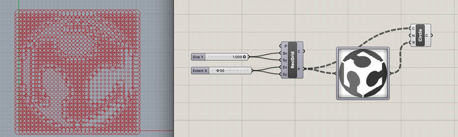
My first impression of this component is that it takes a lot of computing power. Rhino crashes multiple times.
Reflections
This week was so exciting! Since the beginning of Fab Academy I had been looking forward to this wildcard week. Particularly the aspect of biomaterials was compelling to me. And I even had time to experiment with fabrics and fabric-like materials.
One note on these materials: beware of fragile structures with parts that easily fall off. For example, the NASA chainmail was very fragile. Because I want to create robust designs, I decided not to iterate further with this type of geometry. This also applies to 3D printing very tiny shapes on fabric, like circles. If they are too small, they can easily fall off and create pollution. I’m looking forward to develop design strategies that mitigate this effect.
Downloads
- Small fishnet 0.2mm (stl)
- Small fishnet 0.4mm (stl)
- Small fishnet 0.6mm (stl)
- Small fishnet 1.0mm (stl)
- Small fishnet 2.0mm (stl)
- Medium fishnet 0.2mm (stl)
- Medium fishnet 0.4mm (stl)
- Design file for lasercutting bioplastics (dxf)
- Kirigami experiment Illustrator file (ai)
- Hexagonal figure (svg)
- 3D printing on fabric test 1 (stl)
- 3D printing on fabric test 2 (stl)
- 3D printing on fabric test 3 (stl)
- Halftone image Fab Academy logo (dxf)
Designed by others, tested on 3D printer:
- NASA Fabric Hexagon Sheet Small (stl) or on Thingiverse
- Chainmail sample (stl) or on Thingiverse and my attempt to recreate it in Grasshopper (stl) and (dxf)
Explore more like this
Week 17 Invention, Intellectual Property and Business Models
After acing through the technical assignments of Fab Academy, the last two weeks have a lighter load so we can focus on the final project. But this does not mean...
Week 16 Applications and Implications
Propose a final project masterpiece that integrates the range of units covered, answering: