Week 9 Mechanical and Machine Design
In the summary below, you can jump directly to topics.
Summary
Machine week! This is one of the most interesting weeks during Fab Academy, because it’s the only group project and we combine skills from other weeks, including CAD design, 2D and 3D manufacturing, embedded programming, input and output devices.
Assignments
Group project:
- design a machine that includes mechanism+actuation+automation
- build the mechanical parts and operate it manually
- document the group project and your individual contribution
- Actuate and automate your machine.
Individual assignment:
- Document your individual contribution
Learning outcomes
- Work and communicate effectively in a team and independently
- Design, plan and build a system
- Analyse and solve technical problems
- Recognise opportunities for improvements in the design
This week’s results
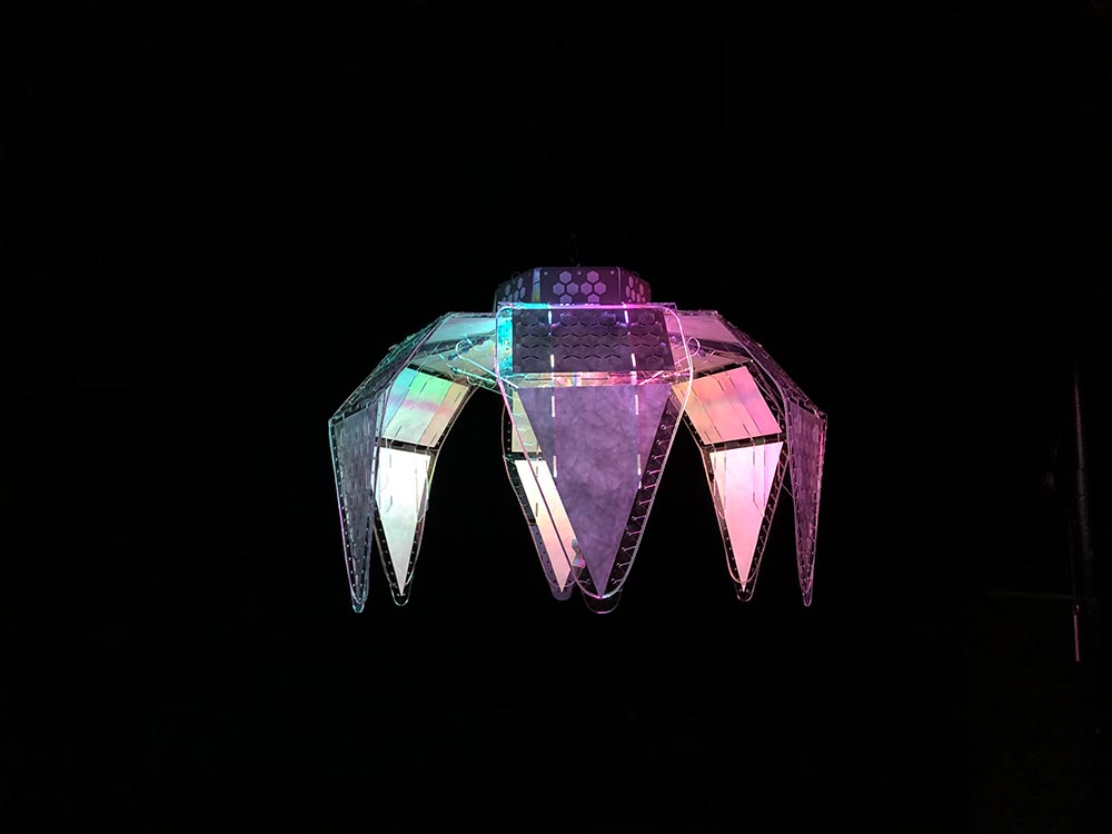
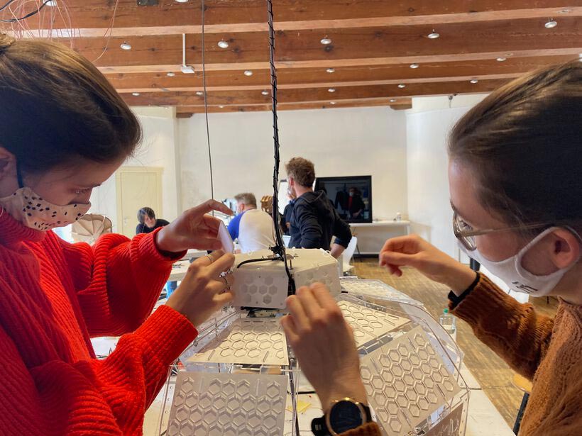
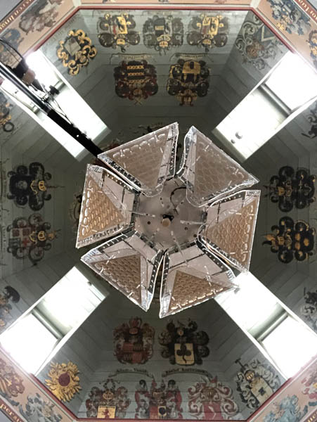
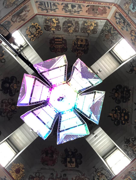
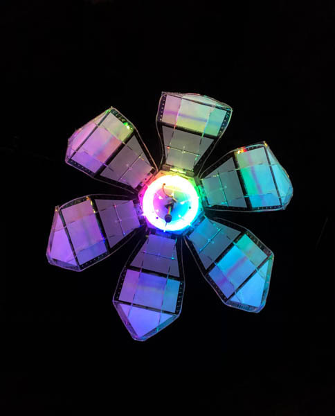
Our Waag group was split up in two teams and therefore two machines were created. Together with Loes, Nadieh and Douwe we built an interactive lamp: Flo. Follow the link to our group page to see what our individual contributions were and how it all came together. Meet Flo, a flower lamp responsive to light:
The other group created Pat-on-the-back-o-matic, a funny (and rather scary) shoulder patting machine based on our Fab instructor Henk. He looks so alike, every time I walk by I think it’s him!
Project management
During machine week, project management is extra important because we work in a team! Therefore, this section provides an overview of our process.
Design inspiration
After the lecture and group formation, we started with sharing project ideas on Mattermost. For the design of the responsive lamp, we came up with the following video’s:
- Inspiration 1: Responsive facade with origami folded geometry
- Inspiration 2: Kinetic smart facade prototype
- Inspiration 3: Mechanical tulip
- Inspiration 4: Mechanical flower
- Inspiration 5: Shylight by Studio Drift
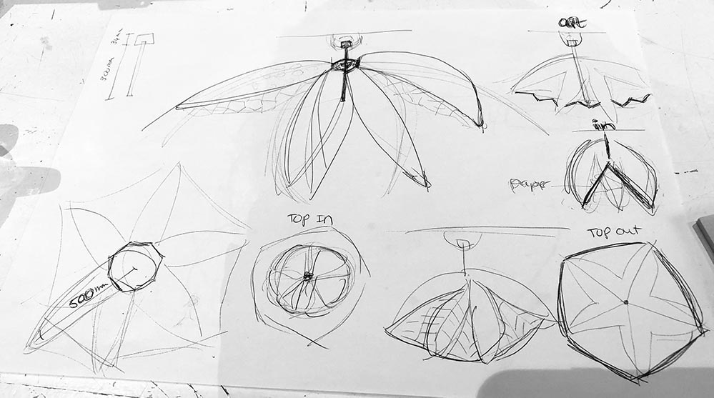
Mechanical system in video 2: a stepper motor pushes five connectors outward.
From video 3: a metal pin is placed through the petal to fix it to the plateau and facilitate rotational movement. This is invisible from the top.
Here is a first sketch I made of how the lamp’s petals and motor system could come together with Nadieh’s origami paper folding techniques:
After a good night of sleep, we were ready for the brainstorm session.
Brainstorm session
Our group came together on Thursday. For a smooth process towards settling on one project idea I facilitated a 2-hours design session. First, each of us had the opportunity to share what our impressions and interpretations of last night’s ideas were. Here are the notes of this session (partially in Dutch).
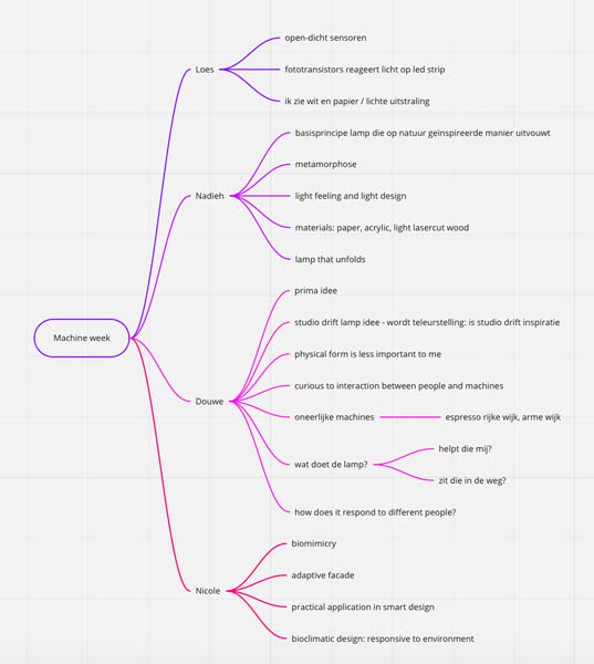
To summarize, we were interested in creating an object that would still be a machine, but could also be art. Exactly at this intersection we would all feel comfortable. Our next step was to dissect the project into individual elements. To make this machine we have to think about five elements: the concept, functionality, interaction, design and materials.
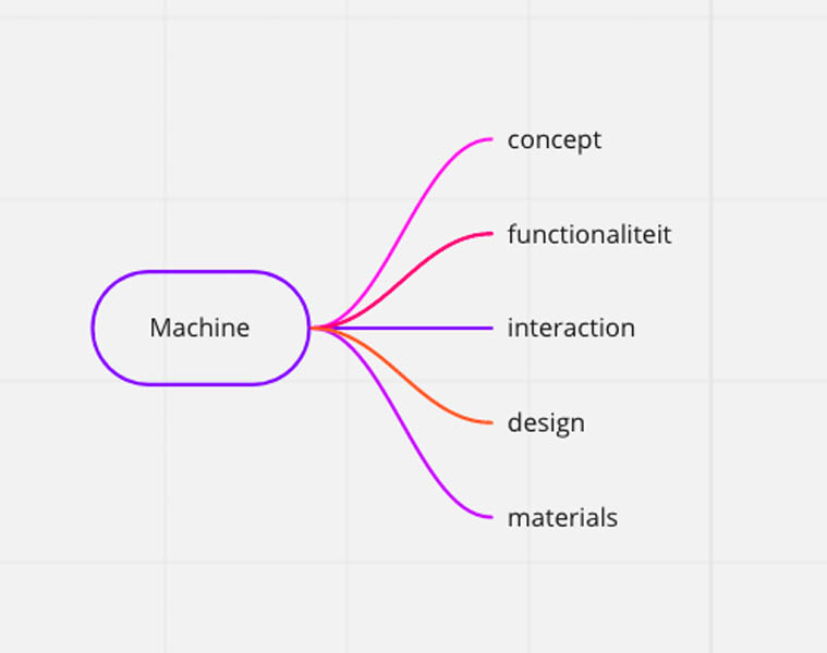
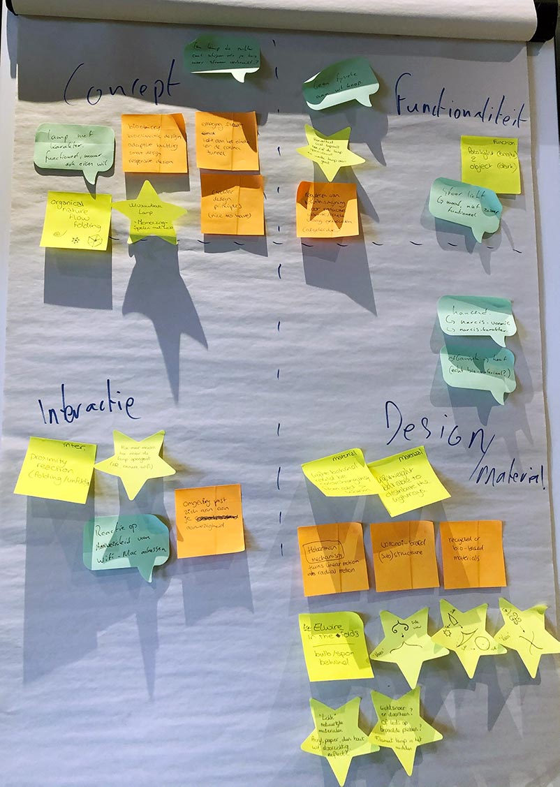
With this information, we continued in a second design session. To narrow down the main idea for each of the elements, we all picked a sticky note color and jotted down our ideas for 5 minutes. After that, everyone briefly presented their thoughts. This brought more clarity to the details of the project.
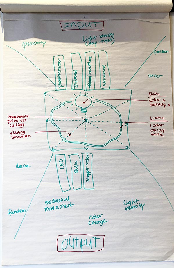
After we settled on the most important details I started to summarize the project in a first draft of a technical system diagram. Above you can see a selection of potential input devices needed. These are: a phototransistor, infrared sensor, microphone and/or ultrasound. In the center you can see a representation of the machine itself. Below are all output devices. These are LEDs, a light bulb and a stepper motor.
Division of tasks
After settling on the most important technical and design objectives, we divided the tasks among our team members. We started with a short brainstorm on what each of us would be interested in.
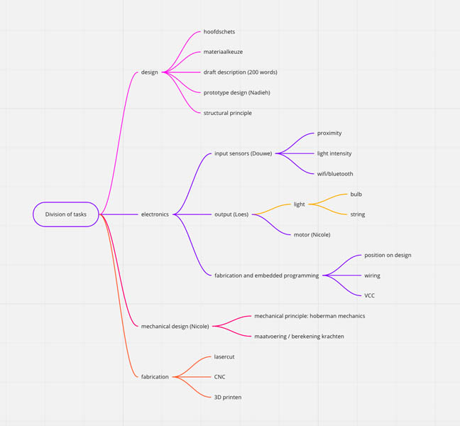
We naturally gravitated towards topics we were most interested in and also kept in mind that we had to finish this complex project in time. Because there is little time we decided to hone in on our existing skill set and/or professional interests. This summarizes to:
| Student | Tasks |
|---|---|
| Nadieh | Petal and origami design |
| Nicole | Mechanical design plateaus + motor |
| Douwe | Input devices: sensors |
| Loes | Output devices: light |
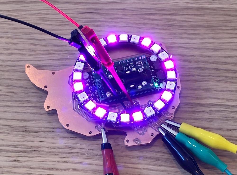
Loes is a light designer and focused on the LEDs in our project: the NeoPixels and EL wire. She soldered the hardware pieces and programmed the LEDs. Douwe made the video and worked on the input devices. Our initial plan was to make the flower respond to light and the presence of people in a room. Due to time constraints we decided to drop the latter. Nadieh designed the beautiful petals, did some experimentation with origami paper folding and took a lead in fabricating the entire thing. She also wrote the code for the stepper motor, supported Loes with the code for LEDs and did an amazing job in bringing all the code pieces together. My contribution was the design of the mechanical parts and two decorative parts. On the first day, I also facilitated a design session to help converge all our ideas into one clear project with well-defined boundaries and tasks.
We made sure to communicate well at the intersections of our individual tasks. For example, it was important to know the dimensions of the sensors, wires and circuit boards to make sure they integrate well in the petal and platform design. In my experience, this went really well throughout the weeks and we were able to present a beautiful video and live demo during the regional and global presentations.
Individual planning
After settling on the team’s goals, I made a more detailed overview of my tasks with a time estimation for completing them. At the beginning of Fab Academy we noticed a break in the schedule, and a few team members (including me) planned a trip during this ‘break’. One week before machine week we discovered that it was not actually a break. Therefore we decided to front-load most of the work in the first week.
| Spiral | Tasks | Time |
|---|---|---|
| 1 | Group brainstorm session | 4 hours |
| 2 | Design of mechanical parts | 16 hours |
| 3 | Prototyping and iteration: file preparation and laser cutting | 8 hours |
| 4 | Stepper motor hardware | 4 hours |
| 5 | Stepper motor programming and testing | 8 hours |
| 6 | Parametric design of cap and top cover | 8 hours |
| 7 | 3D printing of cap and top cover | 4 hours |
| 8 | Group meetings, check-ins, bringing it all together | 8 hours |
Let’s get started!
Design of the mechanical system
For this assignment, Fusion360 was the CAD program of choice. Throughout the weeks I’ve been working in Rhino and Grasshopper. Because I’m responsible for the mechanical components and the connections between the base structure and the petals, it makes sense to explore the functionality and simulation features of Fusion. Because I’m new to this software I will explain certain basic steps in detail in this documentation.
In the design phase, Nadieh and I worked closely together to make sure our parts came together. The sharing options provided by Fusion came in handy.
Logbook
- Design + dimensioning of plateaus
- Animation of total construction (angle of movement petals)
- Connections between leafs and middle plateau (scharnieren)
- Connector physical tests + CAD design
- Positioning of connector (together)
- Collecting bolts and nuts at Waag
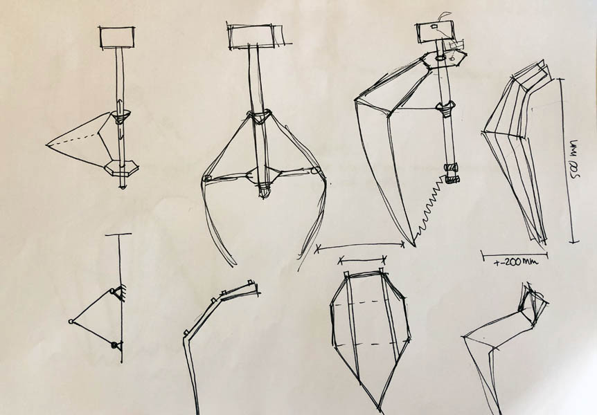
Exploring possible mechanical systems.
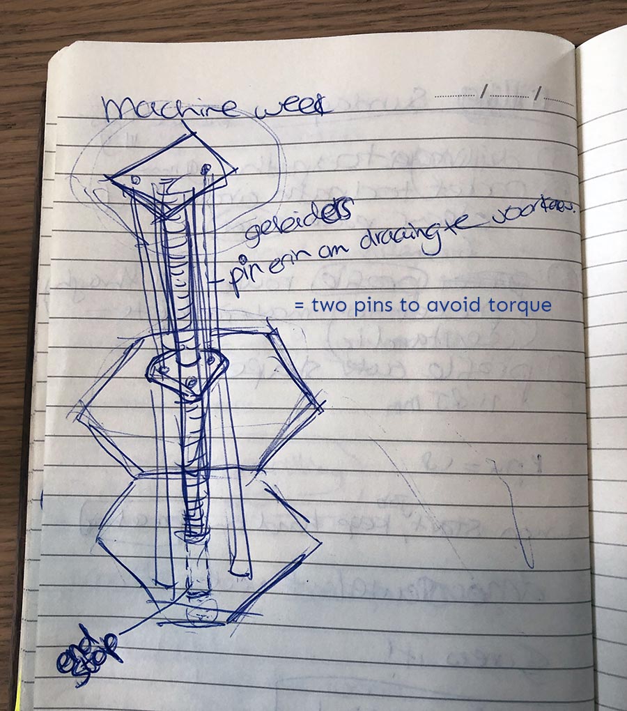
And one sketch to come up with a solution to avoid torque. We ended up not needing them, because the flange nut does not rotate if it is fixed to the petals.
Detailing the mechanism and a representation of one petal in a more technical sketch.
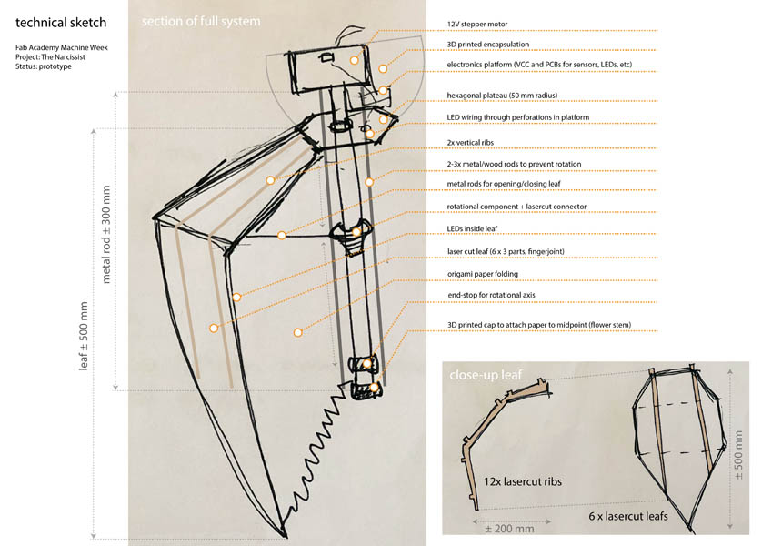
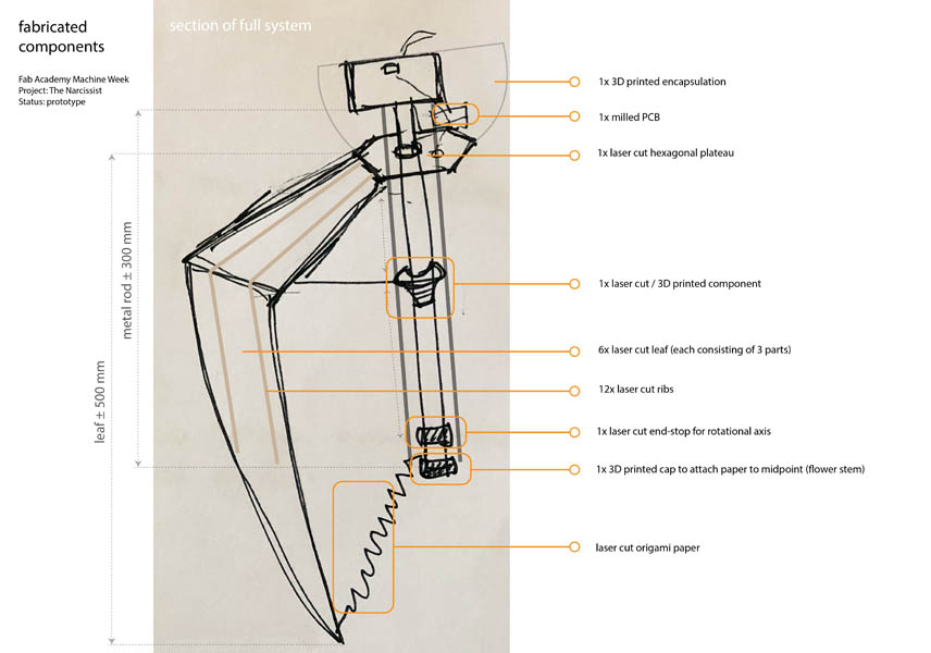
Next, I made an overview of the to-be fabricated components and their position relative to the lamp.
With this general design of the mechanical system I was ready to make it in CAD software. At the core of the design I had to keep in mind the following requirements:
- Enough space for LED ring
- Enough space to fit the circuit boards
- Space for the wires, and a way to hide them
- Strong enough to lift the petals, withstanding torque
- Fixation point for connection to ceiling
- Attachment points for folding lines: 2D origami design in javascript/python by Nadieh
In parallel to this design process, Nadieh made the beautiful design of the petals. We met a couple of times in a video call and decided on a hexagonal overall structure. This informed the shape of the three plateaus.
First plateau
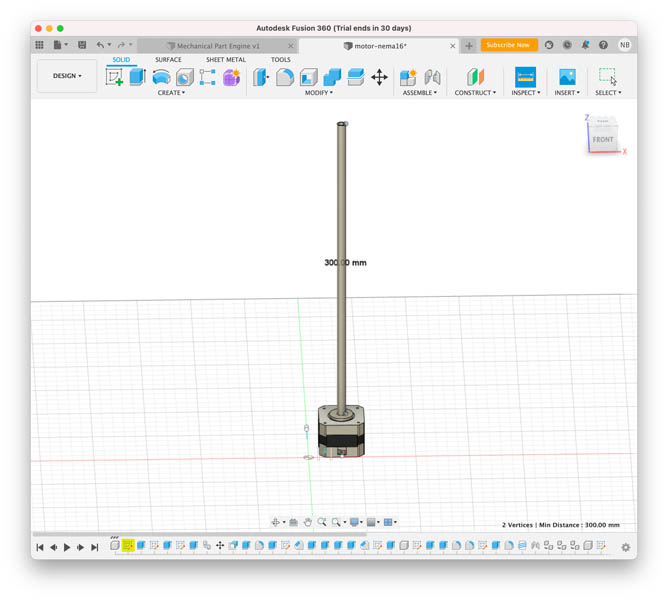
I started with searching for stepper motors online. After searching for about an hour I found a suitable design file of the NEMA-16 stepper motor on Autodesk online gallery. I imported this in Fusion and played with the Animation functionality. The video below shows the components of this motor.
Next, I made a Sketch and added a 300mm long thread on top of the motor.
Then I added the first plateau.
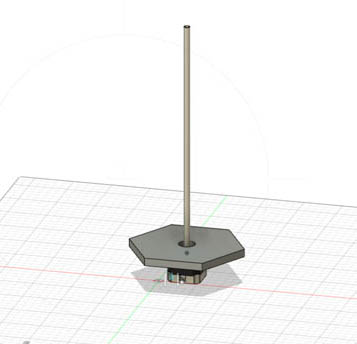
Next, I thought it would be nice for the render and/or simulation to add a real thread. This appears to be a functionality in Fusion. You can even adjust the size, type and direction. The thread size we’re using is an M8.
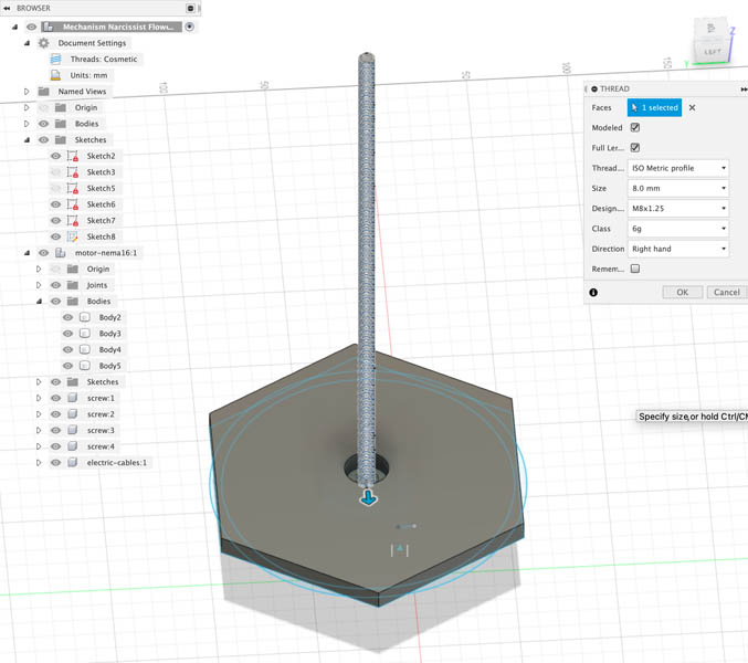
Turning the design upside down to put the lamp in its final position.
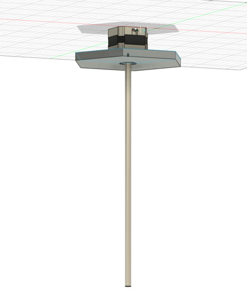
The base is now ready. In the meantime, Nadieh finished the first draft of the petals. In the next section I bring both elements together and simulate the movement. This helps in getting an idea of how the actual lamp will look like.
Simulation of the lamp’s mechanical movement
To me, it was important to integrate the petal design and mechanical system as soon as possible. First, to get an overall impression of the final design. Second, to check if all dimensions are correct. In my experience in the construction industry, it is best to change major elements early on in the design process during the concept design phase. Later in the final design phase you can specify details and make minor adjustments.
Below you can see a picture of Nadieh’s petals, she sent it exactly at the same time when I worked out the overall mechanics and finished the first plateau. She was real quick with designing this!
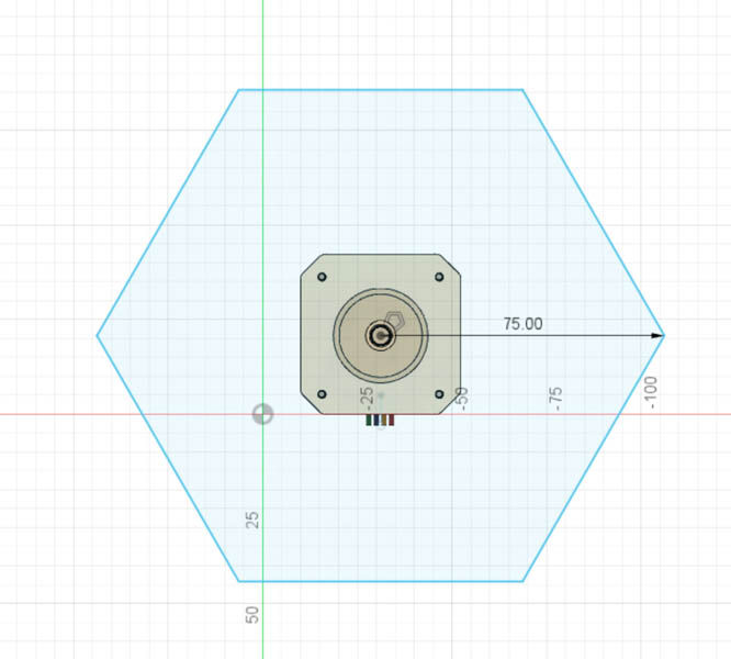
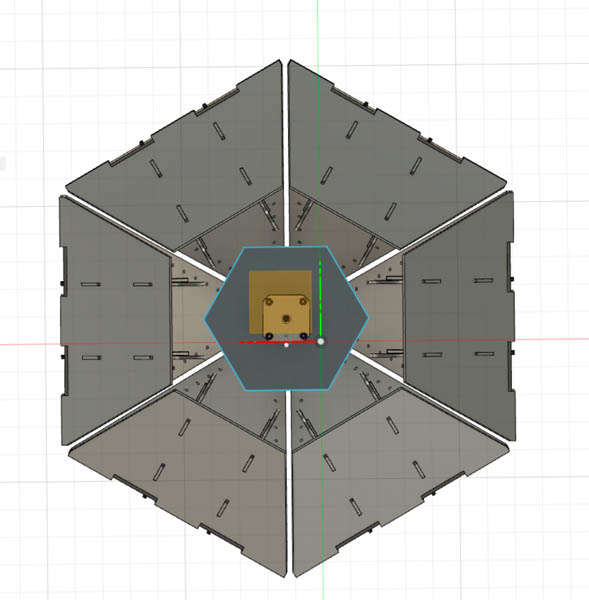
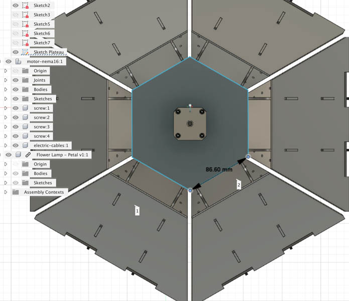
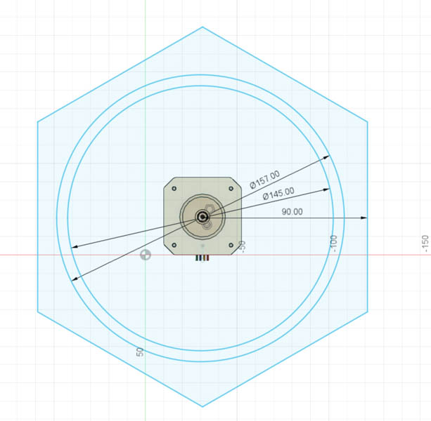
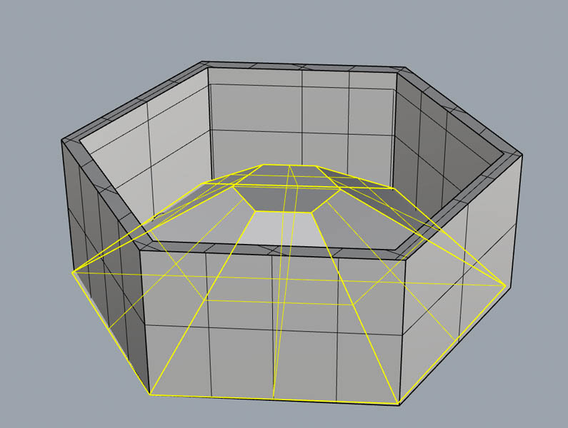
I combined the two designs and noticed that the plateau was rather small. Below you can see the difference between a plateau of 75 mm and 86,6 mm. I scaled it up a little to make it large enough for the petals.
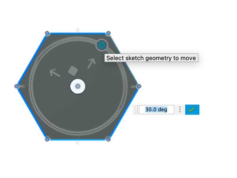
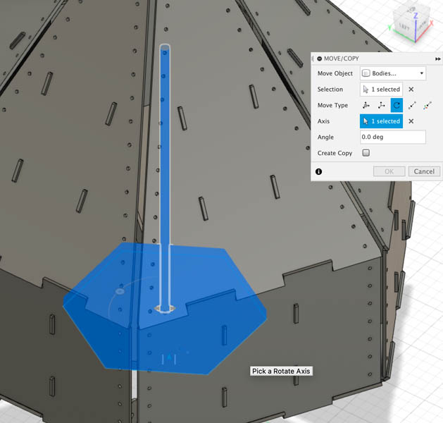
Next, I rotated the plateau and aligned this with the petals. To do this in Fusion, you select the geometry you want to rotate, and then pick a rotation axis. The thread is exactly at the center of the geometry, so that was easy to select.
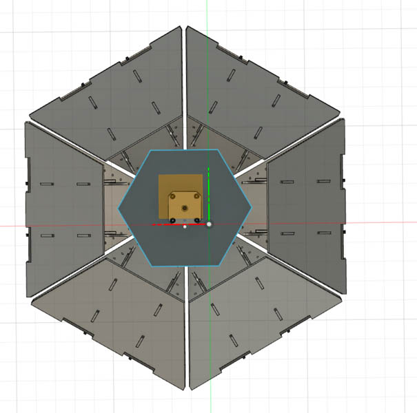
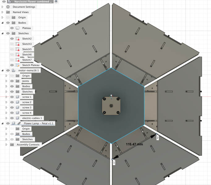
Now the two designs fit together perfectly. To double-check the dimensions, I measured the side of the plateau at 86.6 mm and the petal size at 115.47 mm. Here you can also see that the contact points of the ribs fit within the plateaus.
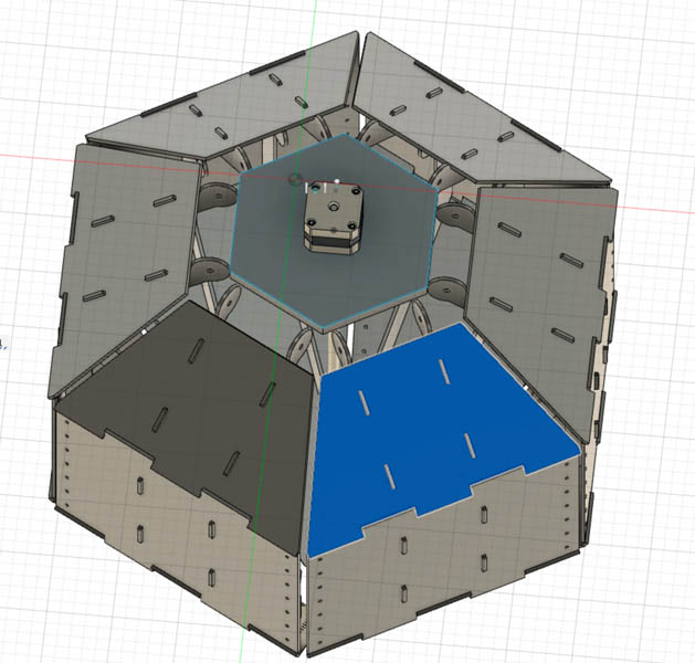
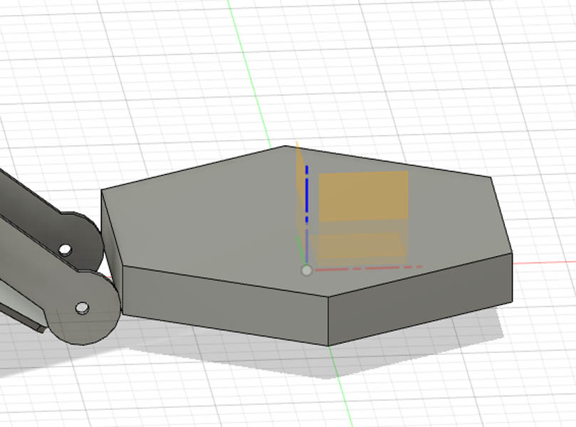
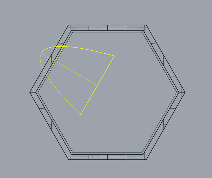
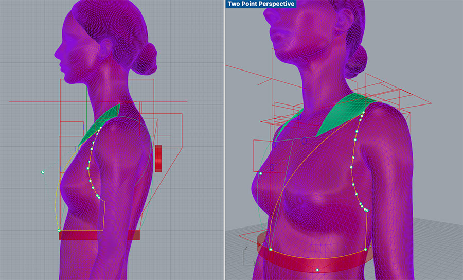
Through this exercise I noticed that the current design of the ribs would introduce a moment in the rib, making it unnecessarily difficult for the motor to lift the petals. I also suspected that the connection between the petal and plateau would be too fragile. It is best if the distance between the plateau and petal is as small as possible. To illustrate this I highlighted one petal in the image below.
The moment of a force is a measure of its tendency to cause a body to rotate about a specific point or axis. Moment = Force x Distance or M = (F)(d). Source: MIT
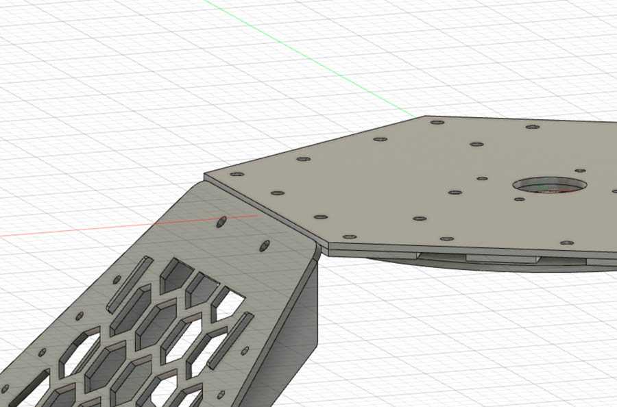
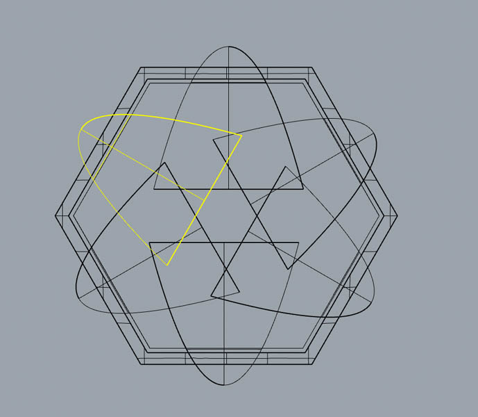
Nadieh agreed with this and updated the petal design. As a consequence, the petals also became smaller to match the dimensions of the plateau. In the new Fusion file, I highlighted one petal and noticed that the new ribs would touch the hexagonal plateau. This means the lamp would not be able to fully close.
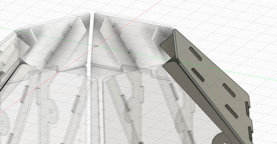
We decided to cut off the ribs vertically and use hinges instead. Thus, we fundamentally changed the function of the ribs and separated the construction into two systems: the ribs for providing structural integrity to the petals, and the hinges for facilitating movement and fixation to the plateau. Below you can see the before and after. The design was updated by Nadieh.
After we solved this, I continued with an estimation of the forces needed to lift the petals. This is important for the material choice, material thickness and dimensioning of the motor. Because I have training in structural engineering, I’m used to working with static forces. However, calculating the movement of the petals requires knowledge about dynamic forces (which is limited in my case). Luckily Fusion 360 has a simulation module, which I was very interested in exploring. Unfortunately this is a paid functionality that requires ‘credits’. So I decided to animate the petals instead in the hope to get a ‘quick and dirty’ estimation. To do this, I started with grouping all the components of each petal together. This ended up being quite a lot of work, because each petal has three leaf components and two rib components. I renamed each of them for further reference.
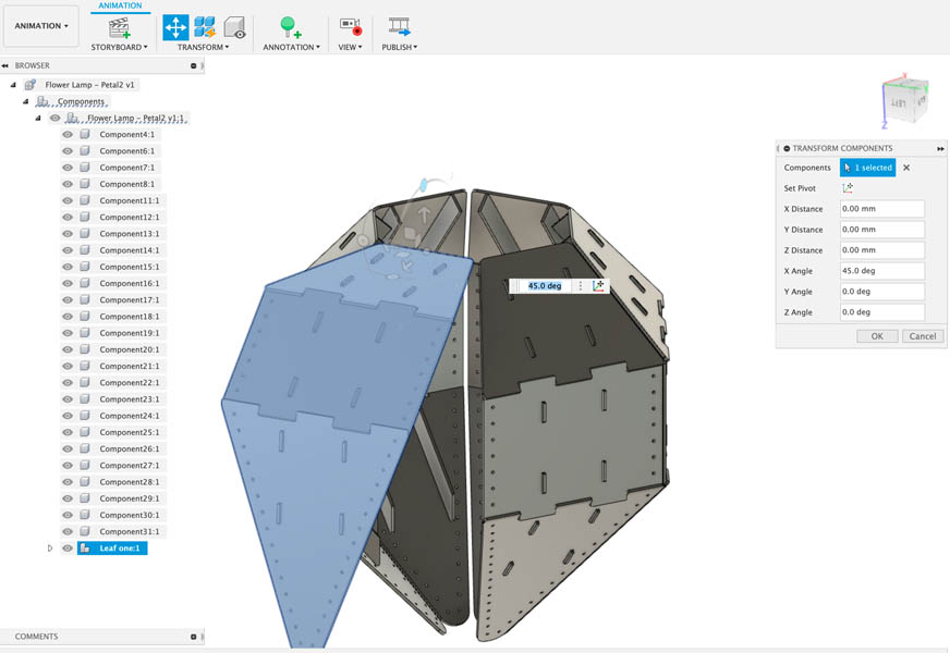
In the Animation tab, you select one group and lift it up with Transform Components. Select the top petal for the correct rotational axis. The petal is lifted at its maximum capacity with an angle of 45 degrees, otherwise it will lift too high and touch the ceiling.
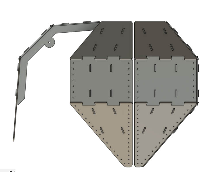
After this initial study, I created a full animation of the flower lamp. This is to demonstrate how it will look like when it changes position from closed to open.
The following step is to finish the top plateau and think about how the lamp will be connected to the ceiling.
Second plateau
As Loes was making progress with the NeoPixel ring and EL wires, it became a bit more clear how much space the electronics required on the platform. I started with adding more details, such as allocating material properties and the NeoPixel ring underneath the platform. Next, I added a second plateau on top of the motor. This second plateau will be connected to the ceiling.
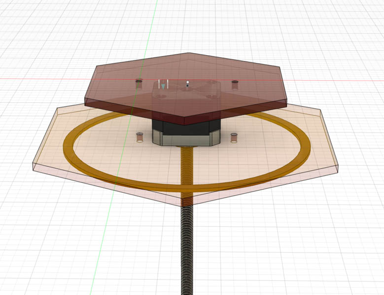
Then I reserved space for two ESP-32’s on top of the first plateau because Douwe and Loes estimated that the motor, LEDs and bluetooth scanning device would not operate on one microcontroller. Then I continued with inspecting the cross-section. This can be activated with the Section Analysis tool.
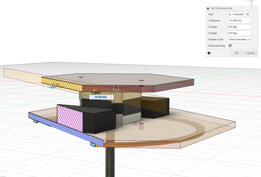
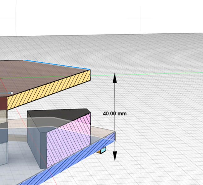
The screws need to be at least 40 mm to bridge the two plateaus.
Adding screws and flange nut
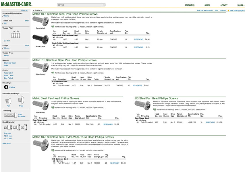
I navigated to the McMaster-Carr website and quickly found out that there are many different types of M5 screws that meet my criteria. The first way to import one of these in a Fusion project is to click on the item and download the CAD file. It’s quite an extensive library!
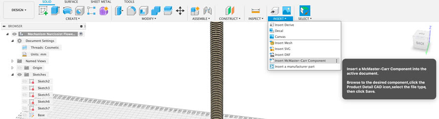
Then I found a Youtube tutorial about Fusion’s functionality to import McMaster Carr items directly within Fusion. That’s quite cool so I wanted to try that out. In the Design environment, navigate to Insert McMaster-Carr Component.
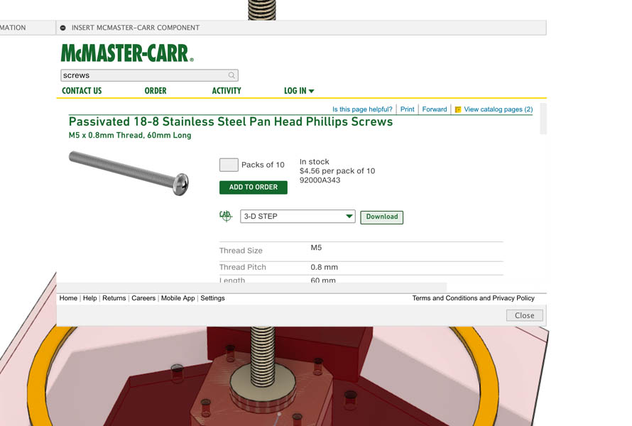
A pop-up screen with the homepage of McMaster-Carr appears. You can navigate to the M5 stainless steel 60 mm and ‘download’ the file. It is important to import as 3-D STEP file instead of a Fusion file because the Fusion file doesn’t work according to the tutorial. I can confirm this.
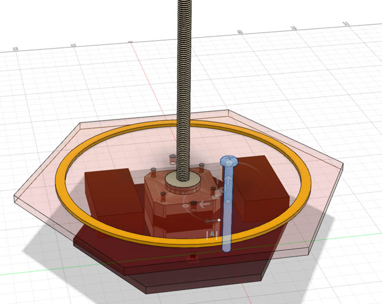
Here you are, beautiful screw.
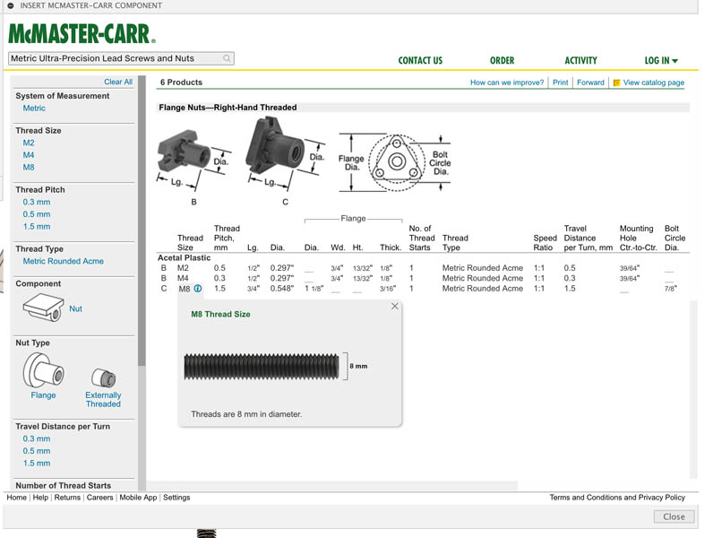
For selecting a flange nut I consulted the Metric Ultra-Precision Lead Screws and Nuts page.
Operating with less backlash (play) than Metric Precision Acme Lead Screws and Nuts, these provide increased nut life and more reliable movement in automated systems. Also known as single-start and self-locking lead screws and nuts, they have a single thread that runs the length of the screw. The nut travels only when the screw turns, so your system won’t unexpectedly move when the lead screw is at rest. To ensure compatibility, select components that have the same thread type and thread size.
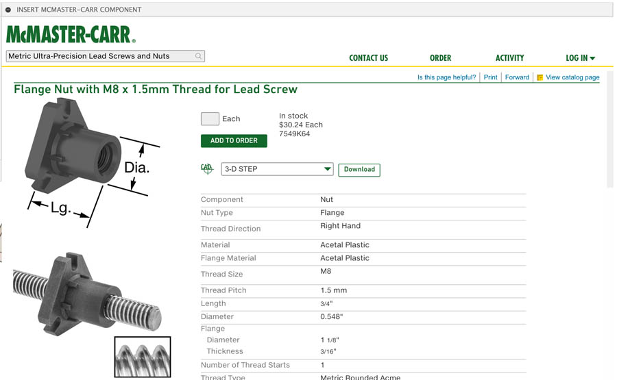
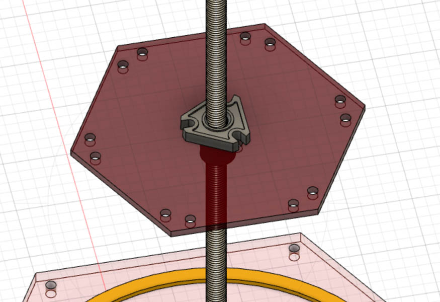
That sounds good, and it looks a lot like the flange nut on the stepper motor that’s available to us. I chose the Flange Nuts—Right-Hand Threaded. The thread size is M8.
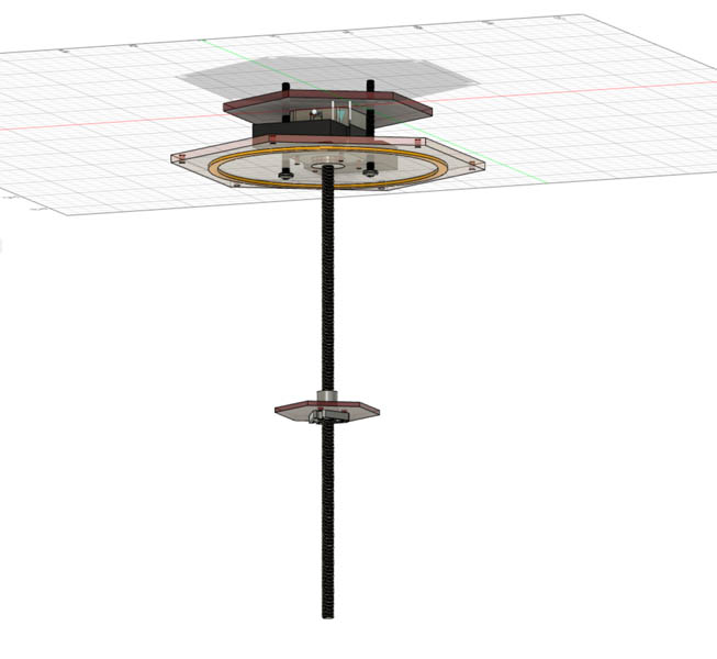
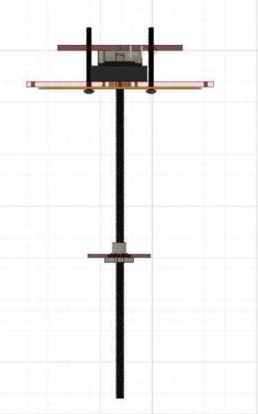
Import it to Fusion with the 3-D STEP file download.
And position it on the thread. Suddenly it starts to look real!
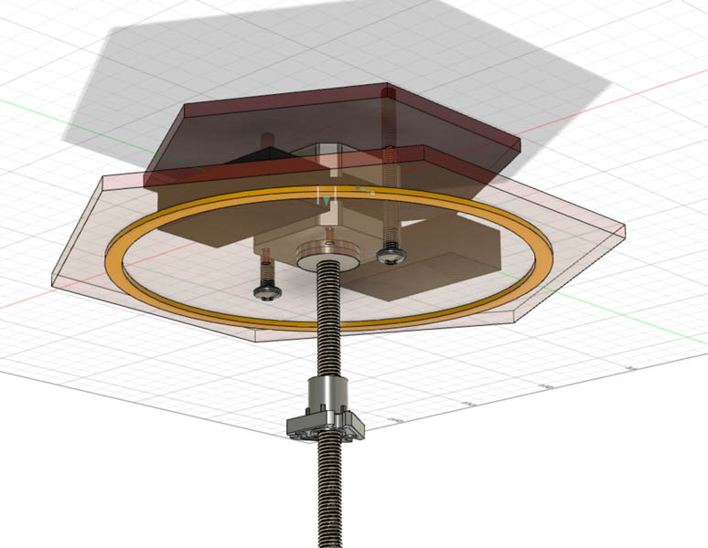
My goal is to visualize the movement of the flange nut to get an impression of the mechanics and find out what the minimum/maximum required travel distance is to lift the petals. For the animation of the flange nut I’d like to specify its Joint Limits, which can be found here.
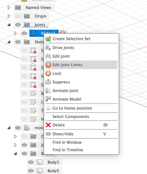
Here is an animation of the result:
Now that the flange nut is ready, I can add a third and final plateau for fixing the petals to it. This plateau moves up and down and will drive the movement of the flower lamp. Because of the dynamic force distribution during movement, it is very important to think about its design carefully.
Third plateau
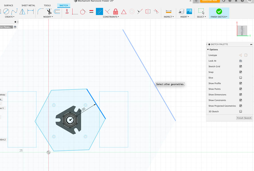
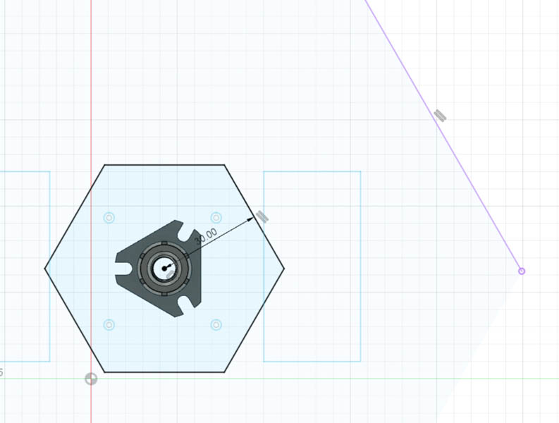
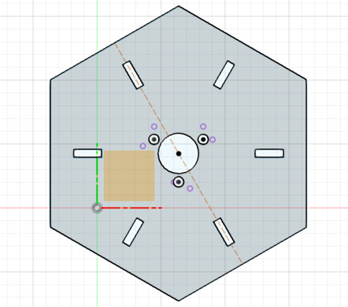
This plateau is also hexagonal to match the overall geometry. To make sure the plateau of the flange nut aligns with the petals you can add a constraint, in this case Parallel (left image). Next, you click the reference geometry. Two small lines appear next to the two lines, indicating that they are in parallel (right image).
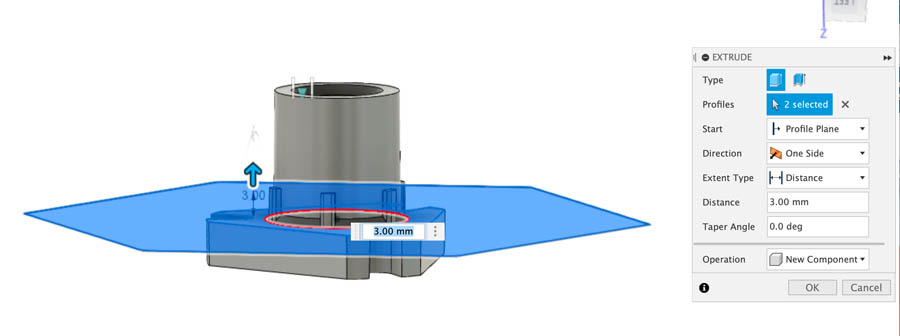
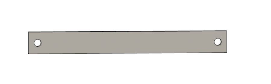
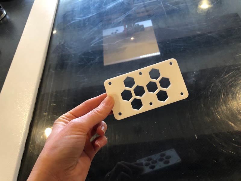
Extruding the sketch to create material thickness. We will most likely use a 3mm acrylic sheet for this element.
Back to the sketch to add references for the bolts and nuts.
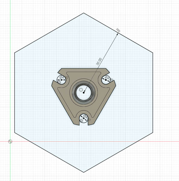
In the design, add Hole to perforate the acrylic sheet.
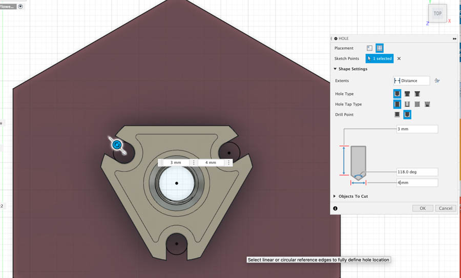
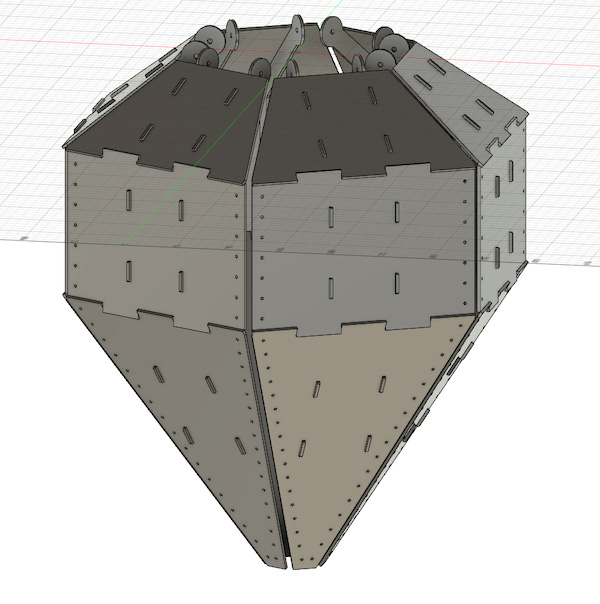
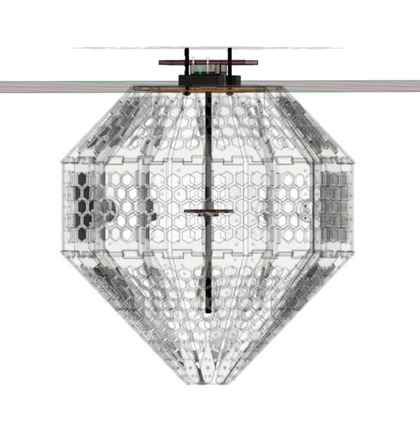
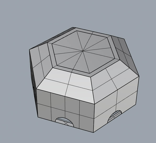
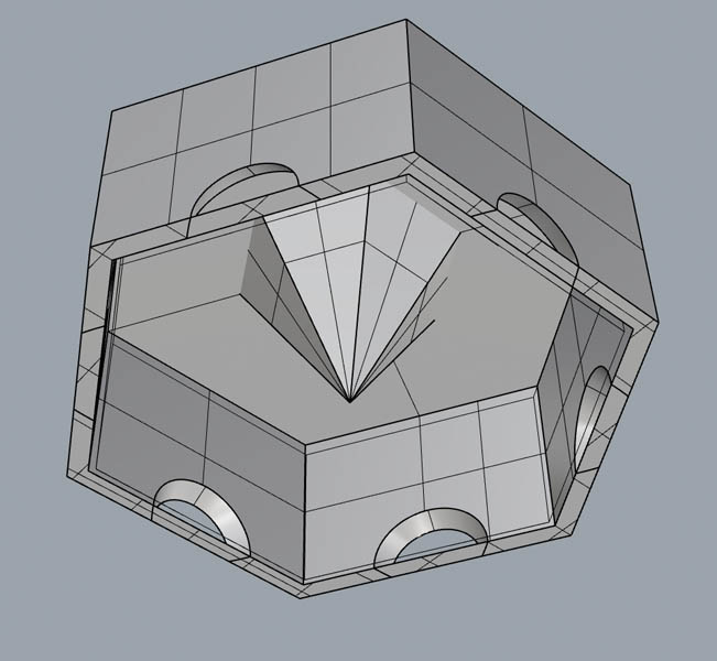
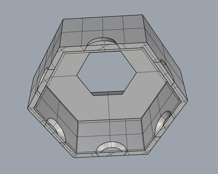
The overall design of the central mechanism in a perspective and side view.
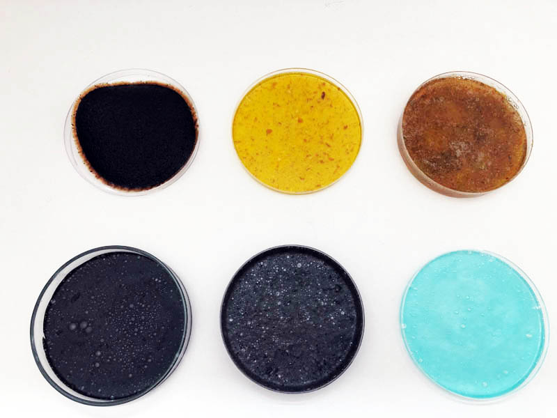
By changing the material properties in Fusion, it becomes possible to inspect the interior and exterior of the lamp. During the prototyping phase, we will lasercut the petals and mechanisms in cardboard. For the final design we are aiming for transparent acrylic. The images below give an impression of both materials.
And last but not least, adding in screw holes on the plateau for connecting it to the petals later on.
After completing the design in CAD we were ready for the first cardboard prototype!
The first prototypes
Nadieh and I finished the design relatively fast, and were able to lasercut and assemble the first prototype on Monday. It was great to work together in-person, as it accelerated our prototyping phase significantly. By the end of the day we had our design version 1.0 ready!
Prepare for laser cutting
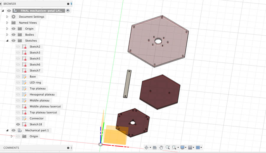
In Fusion, a couple of steps can be taken to prepare the file for laser cutting.
- Hide all components
- Open origin - create new sketch
- Click component
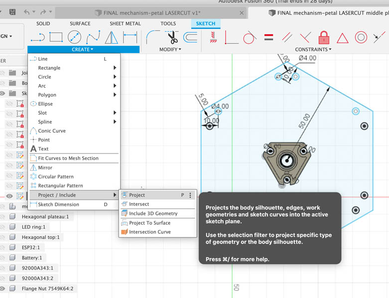
- Project
You can find the Project tool in the Create tab.
Collect all items in a Sketch on one plane.
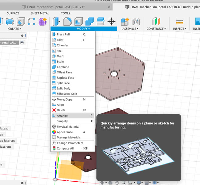
If you want you can nest the parts with the Arrange tool.
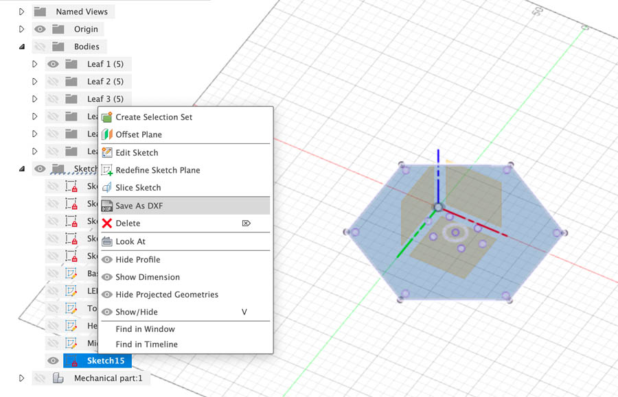
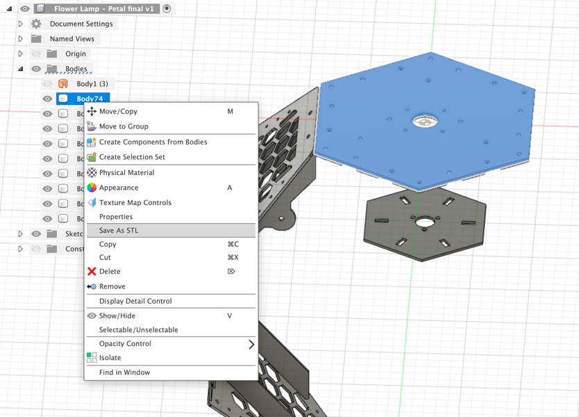
Once you have a projected item, right-click on the Sketch and Save as DXF.
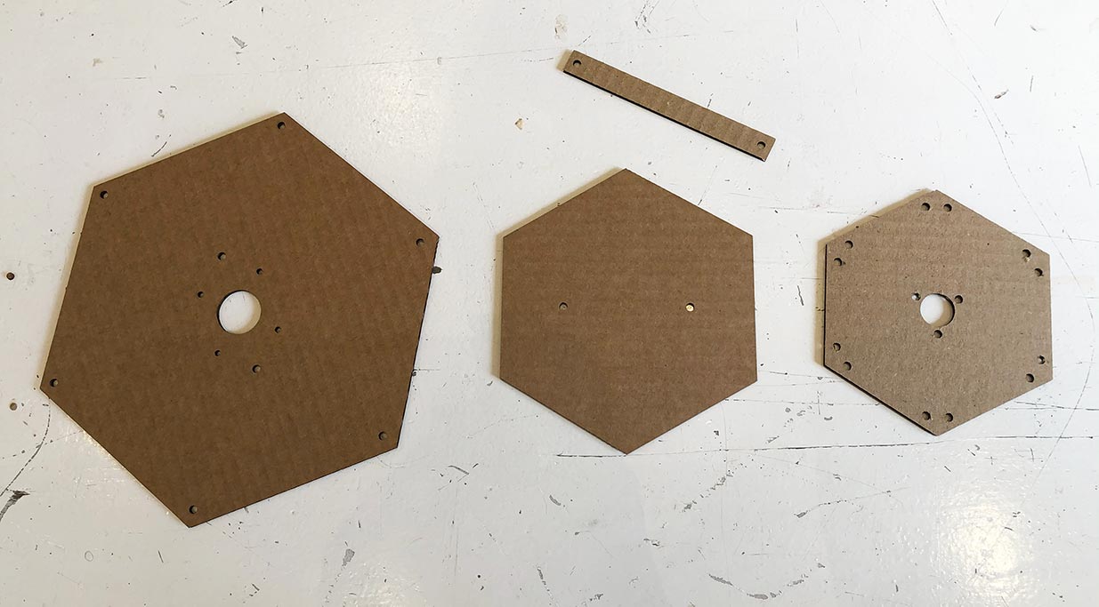
I documented this process for future reference. Here are the files after laser cutting:
Assembly of the first prototype
Before assembling the lamp I asked if there were bolts and nuts available to us. Henk referred to Sunke and she showed a real treasure room upstairs behind one of the most beautiful rooms at Waag. Here I found:
- M4 small bolts and nuts 16 mm
- M8 large thread
- A potential hook for the attachment point to the ceiling
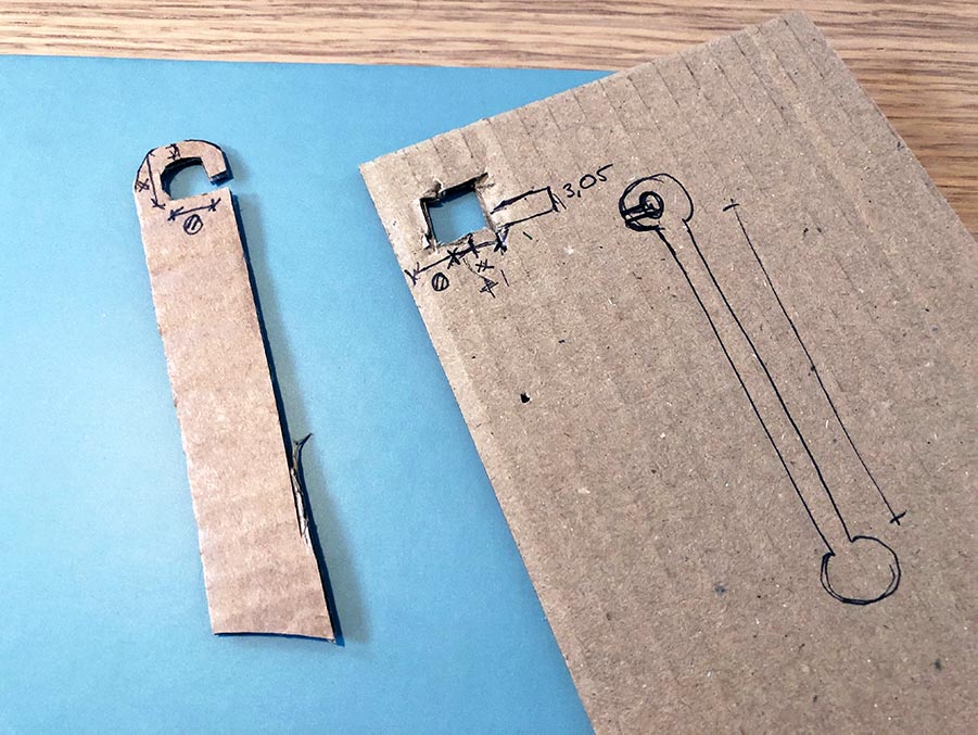
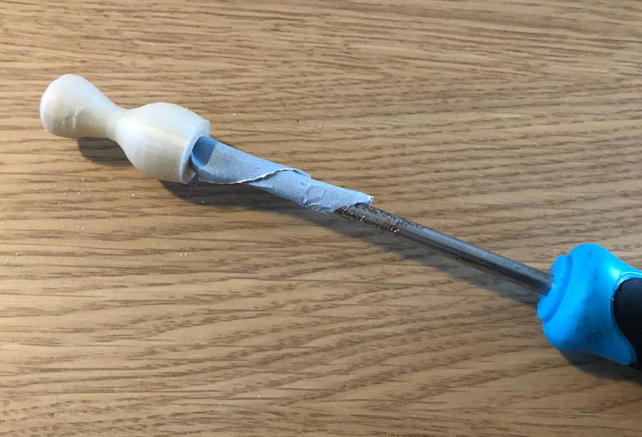
After collecting the materials it was time to play around with the mechanical system for the first time. In Fusion, I quickly designed a simple connector and lasercut it. This is the element in between the moving plateau and the petals. We were so busy designing the petals and mechanical parts that we hadn’t thought about that part yet.
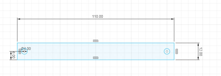
We took a wooden stick from a children’s prototyping box and taped this to the connector to extend it a bit. With an M4 bolt and nut the connector was attached to one rib. And here it is, the first movement. :)
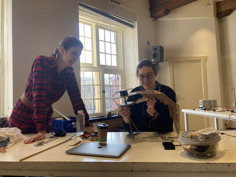
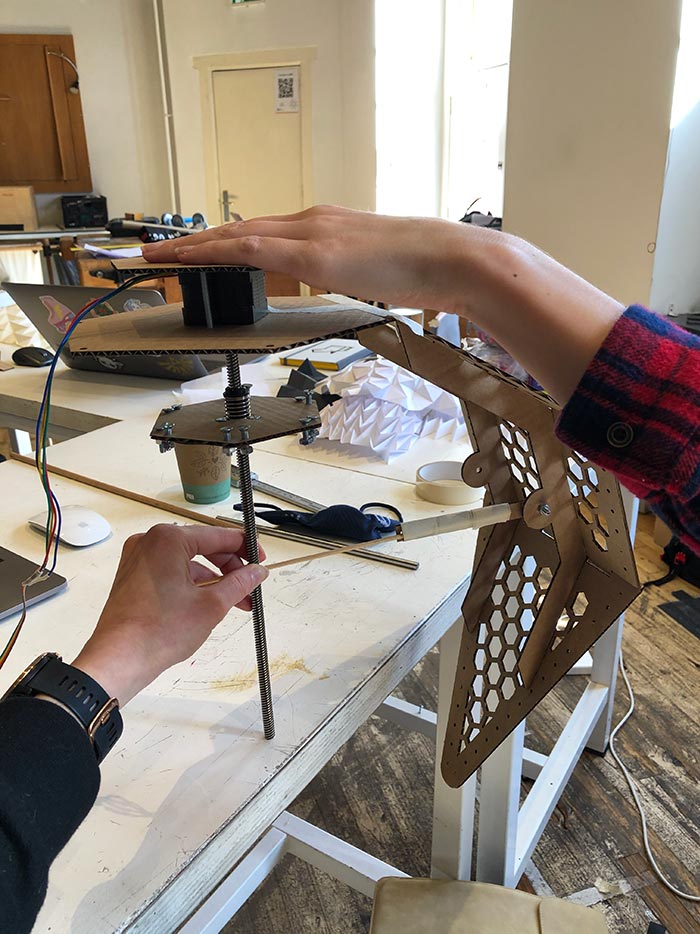
After playing around a bit we concluded that the traveling distance of the flange nut could be optimized. Nadieh added two more attachment points to the ribs of the petals and lasercut it. We tested the travel distance on those three positions and concluded that the top one was best because this one was able to push out the petal most with the least effort. Here is a hero shot of Nadieh showing the movement:
Next, we duplicated our connector-stick and attached this to the other rib of the petal. We quickly learned that this system would create unwanted tension on the side of the moving plateau. The reason was that the distance between the ribs was wider than the width of the hexagonal plateau. In cardboard we can bend the material slightly to make it fit, but this will not work in acrylic.
So I had to come up with a better system. The connection of the moving plateau is inspired on this Youtube video. This is the first prototype:
And a video of how this principle works:
With this new connector the plateau also needed an update, to accommodate for the new connector.
Somehow my Fusion file got really weird. It shifted the holes a little, messing up the entire design. This was really frustrating. Due to time constraints Nadieh recreated it in her Fusion file.
Decorative parts
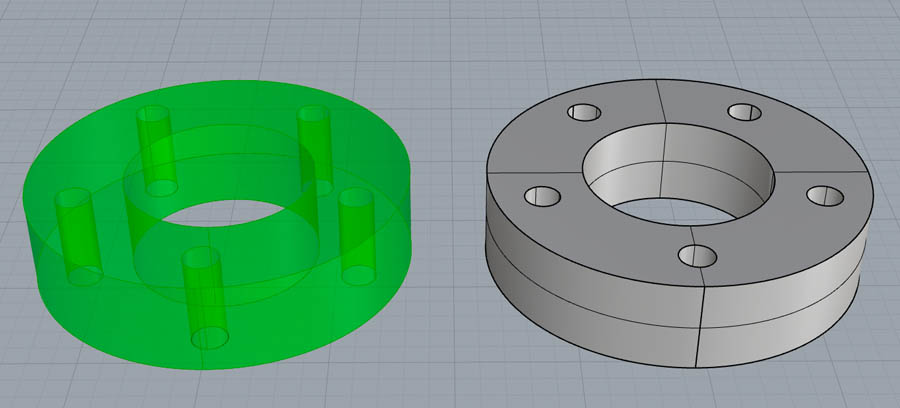
I designed two decorative elements: the flower stigma and the top cover for hiding the circuit boards and cables.
Flower stigma
The two parts of the flower stigma are made with 3D printing. Those are the end-cap and the with an aesthetic function. It symbolizes the stem of the flower. The cap has the following technical requirements:
- An internal diameter of 8 mm and a little bit to fit around the thread
- The thickness of the material should at least be 2 mm
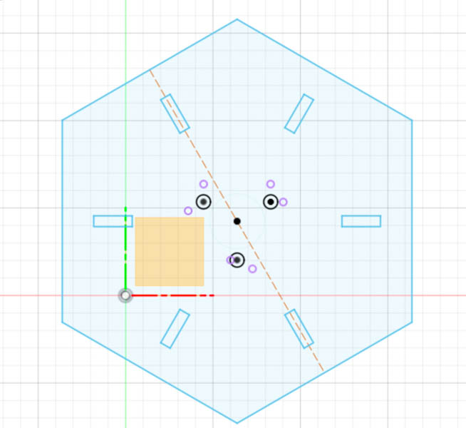
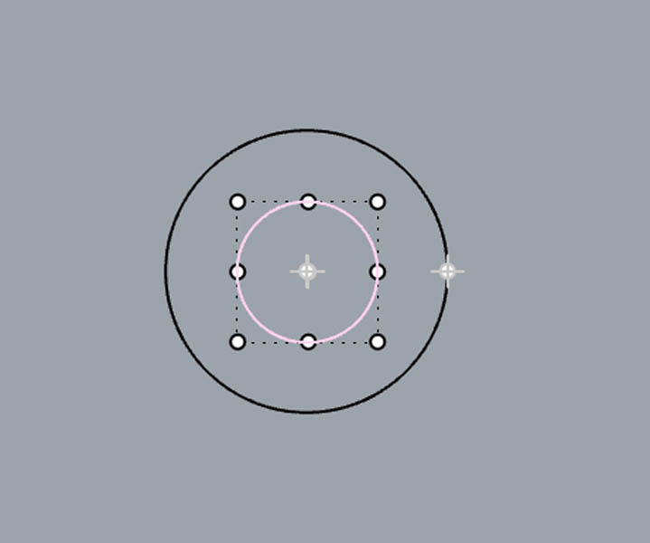
I decided to make the following parts in Rhino and Grasshopper. The design procedure is as follows. I started in 2D with two circles and copied them on a vertical axis with the Array command.
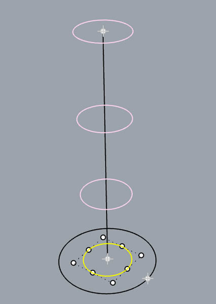
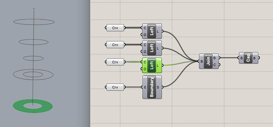
Next, I opened Grasshopper and linked each curve on the canvas. With the Loft function you can create surfaces. The first is the internal diameter. This part slides around the motor’s thread. It should be tight enough to stay there. Therefore, I decided to make the radius exactly 4 mm and potentially sand it if it is too tight.
The second curve is lofted around all outer curves to create the exterior.
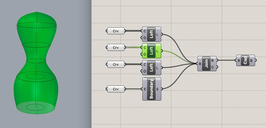
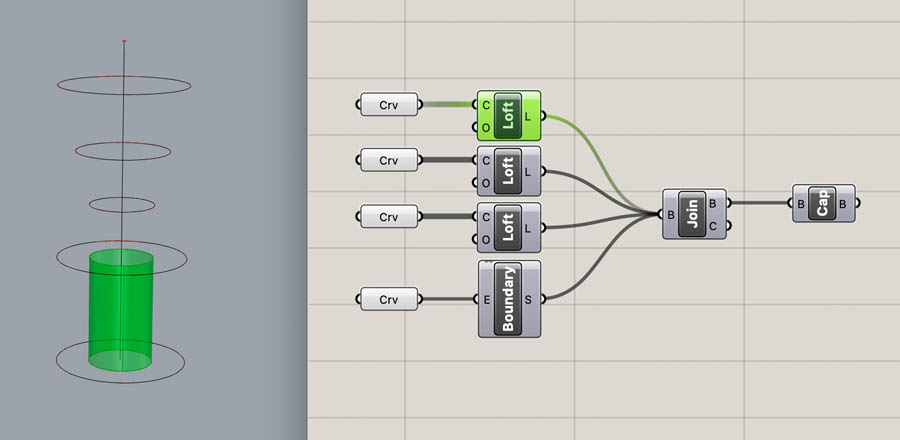
Next, another Loft and a Boundary Surface to
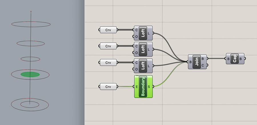
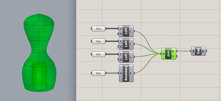
With the Join command you create a boundary representation (Brep) of the geometry. Rhino and Grasshopper work differently than other CAD programs in this regard, because solid objects don’t exist in this environment (which is weird to an engineer!). To create a good .stl file for 3D printing, you have to make the object watertight. For this geometry this can be done with the Cap Holes component. Right click the Cap component and Bake the geometry in Rhino. Then you can mesh it and export as STL.
The second part of the flower stigma is a ring that fixes Nadieh’s origami designs. I started with a 2D geometry in Rhino.
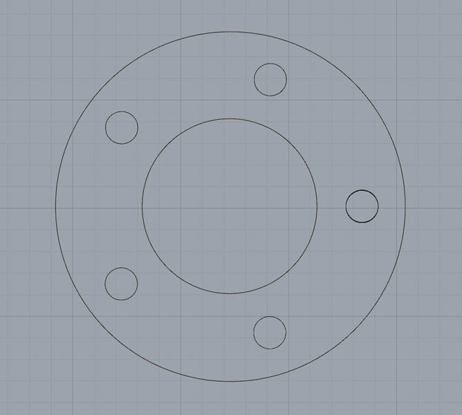
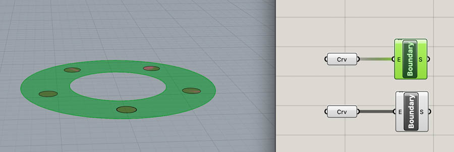
Next, the curves were linked in Grasshopper, and two Boundary Surfaces were created.
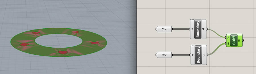
To make the holes, use the Surface Difference component to subtract one geometry from the other.
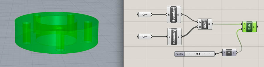
And Extrude the remaining design with 4 mm.
Bake this in Rhino and export as STL.
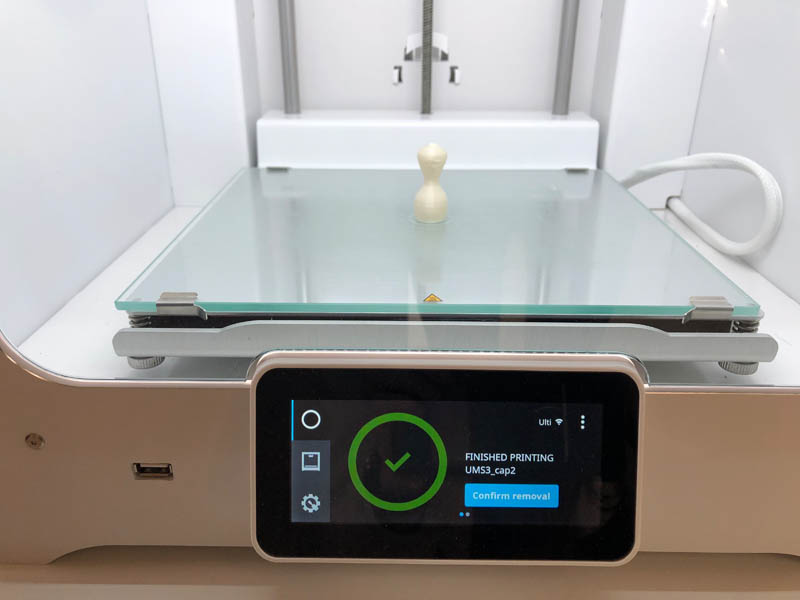
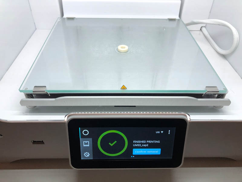
Then I sent both files to the 3D printer.
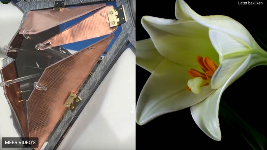
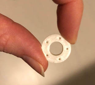
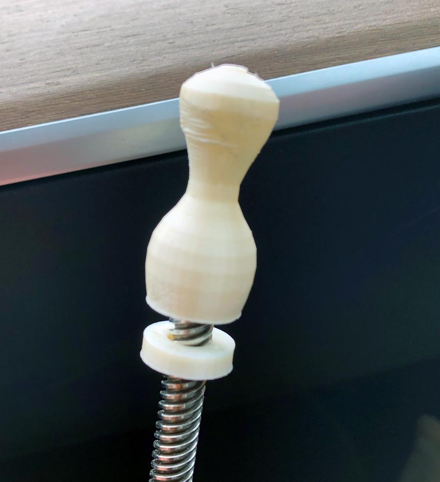
Below, the image on the left is a close-up of the ring. The image in the middle shows that some sanding was needed to fit the flower stigma on the thread. At this point the origami wasn’t finished yet, so I came up with a strategy to connect the paper in two ways: the first is with fishing wire through the perforations, and the second by locking the paper in between this ring and the flower stigma, see image on the right.
Eventually we ended up not doing the origami, so the ring was not used in the final design of the lamp.
System integration of electronics
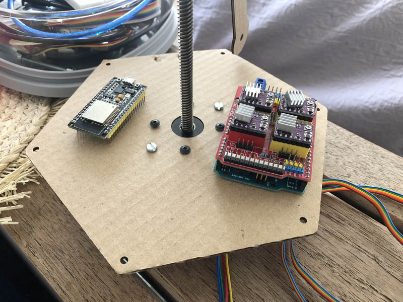
An important challenge of this project is to hide all electronics, to make the lamp look nice. Early on in the process, I reserved plenty of space for an Arduino with CNC shield and the ESP32 on the first plateau.
The second plateau that comes on top of this would provide the base for a 3D-printed cover. My first idea was to slide this from above around the smaller top plateau and use gravity and notches to snap it in place on the center plateau. As you can see in the image below, the original design had a smaller top plateau, so the cover would get a tapered design.
Here is the initial Rhino design. The ‘Tom and Jerry’ holes are for the cables. My general working principle is to start with a rough, main design, test it, and then continue with details. After this rough outline, the plan was to carve out hexagons on the surface for a more lightweight feel and less material use.
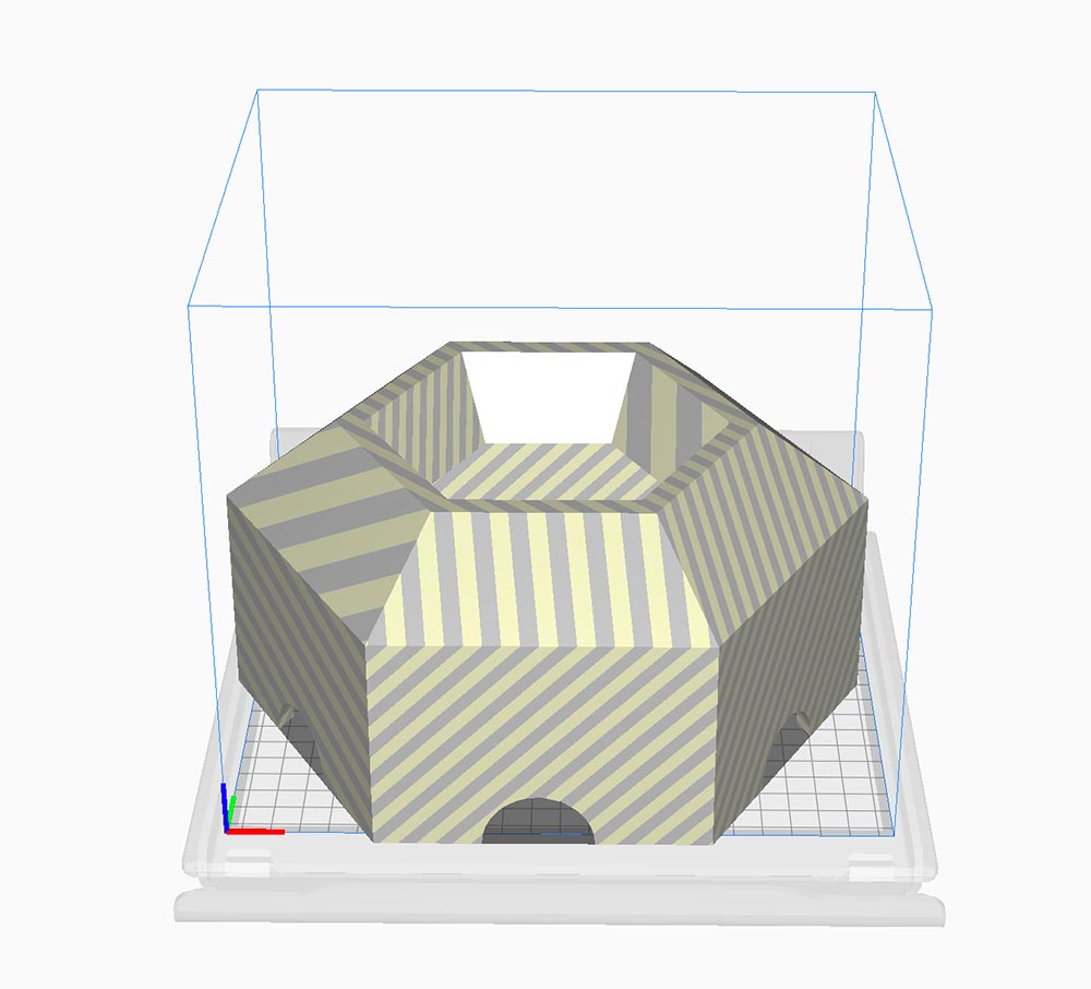
However, a quick file conversion test in Cura software revealed that the design was too big for the 3D printer’s build plate. This was a big disappointment! On the other hand, I was lucky that I did a small test and hadn’t started with detailing the shape yet.
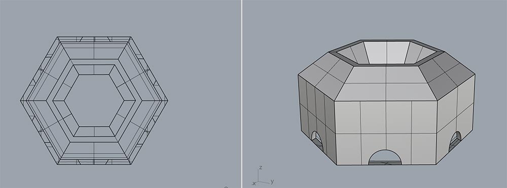
Just for documentation purposes, I’ll include the design process. I started with exporting the center plateau’s dimensions from the Fusion file, and imported this in Rhino.
I started with creating vertical lines and small circles.
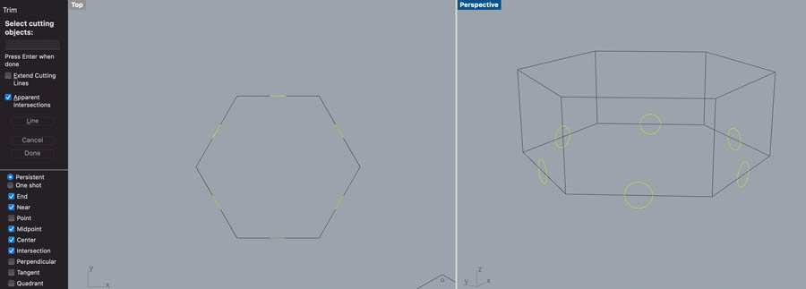
With the Trim command I created the small holes for the wires.
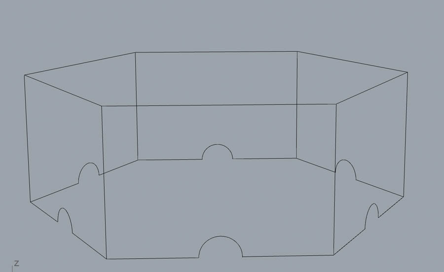
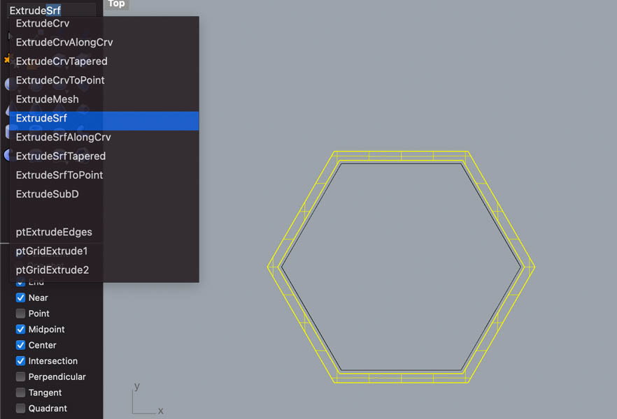
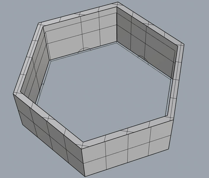
As you can see in the image below, I left a bit of space outside the main geometry to account for 3D printing tolerances. The Offset command was used to create a 2 mm wall. Next, I extruded the surface with ExtrudeSrf.
Then I experimented with creating an internal geometry. I decided not to go this route because it seemed to create a bulky design.
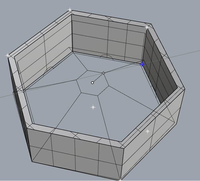
So I continued with a paraboloid to make holes in the walls.
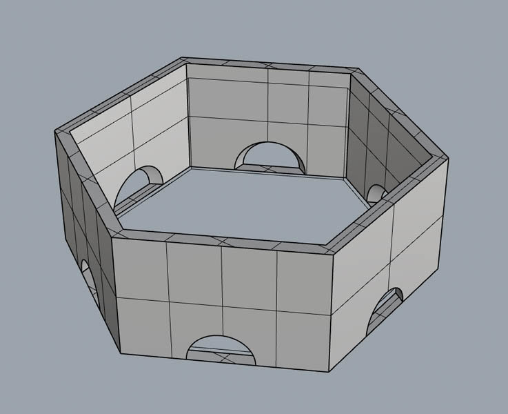
And for the top part, I created another shape to intersect and subtract with. With the BooleanUnion command I closed the geometry into a solid object.
So, that failed. In the meantime, Loes and Nadieh were at Waag and sent this picture of a very messy cable situation. We were in desperate need for a solution to hide the wires and circuit boards.
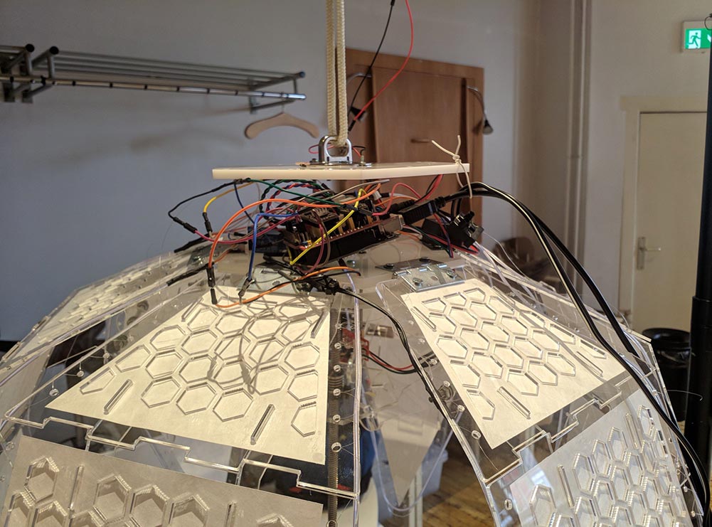
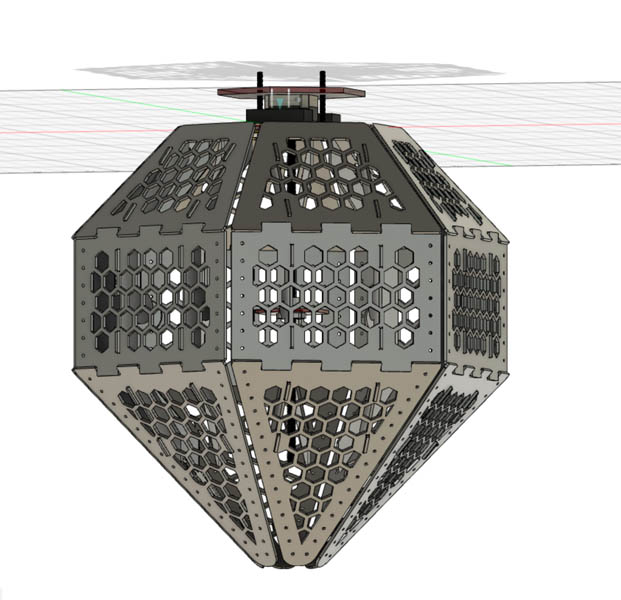
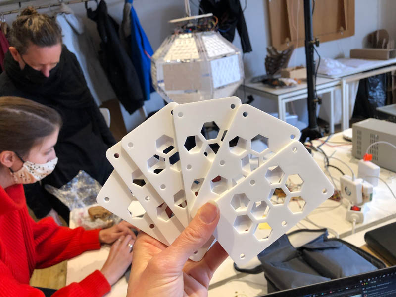
It also turned out that the design of the top plateau had changed. Its dimensions were now equal to the center plateau. In the car to Amsterdam, I came up with a second strategy: to lasercut the parts at Waag instead of 3D printing. With Grasshopper I created a hexagonal grid, baked it into Rhino and did some post-processing by deleting hexagons and adding in perforations for connecting them to the plateaus with fishing wire.

This idea turned out to work, I only had to adjust the outer dimensions of the design a little after I found out that they had changed too. Luckily I made this using Grasshopper, so it was just a matter of adjusting some sliders and baking the result in Rhino. Here is the result after laser cutting!
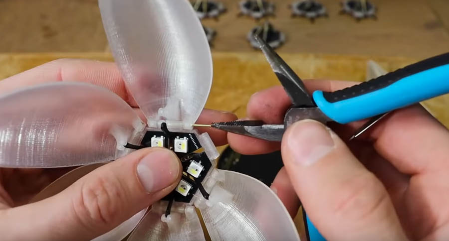
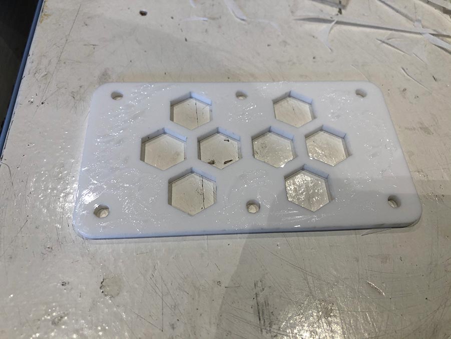
One more step before they could be added to the lamp was to cut out semi-transparent tracing paper and glue this to the back. Because the ESP32 and Arduino CNC shield have some LEDs on it, I hoped that this would give a nice effect.
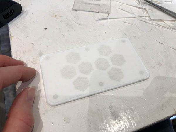
Luckily this worked in the first go! Here are Nadieh and I assembling the plates to the lamp. The idea behind it is to only attach them to the top plateau so you can flip them and reach the electronics at any time if needed.
Motor
Beside the engineering of the technical side of the lamp, we agreed that I would connect and program the motor.
Types of motors
Before we started with the group assignment, Henk provided an overview of the different types of motors available in the lab.
DC motor
- Hard to control on Arduino, because there is only ground and vcc.
- Other motors are derivatives of a DC motor, but they use an H-bridge: crosses + and - for more control.
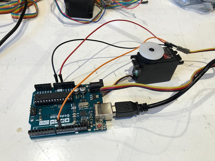
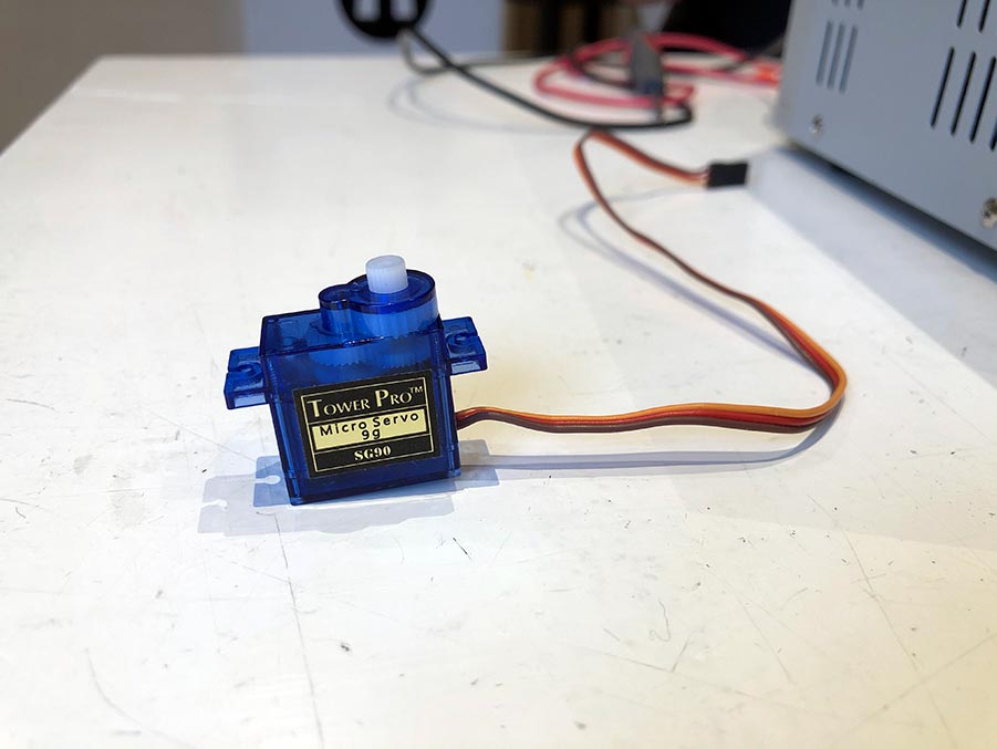
Servo motor
- small blue one, are also bigger
- internal h-bridge + board
- often they can only rotate 180 degrees
- less powerful than stepper motor - can rotate 9 grams
Stepper motor
- External feed by board
- 12V power supply for motors
- Can make 200 steps for 360 degrees rotation
- Microstepping: each step can be divided by 32 in-between steps, this equals to 6400 positions
- End-stop is there for the motor to know where zero is
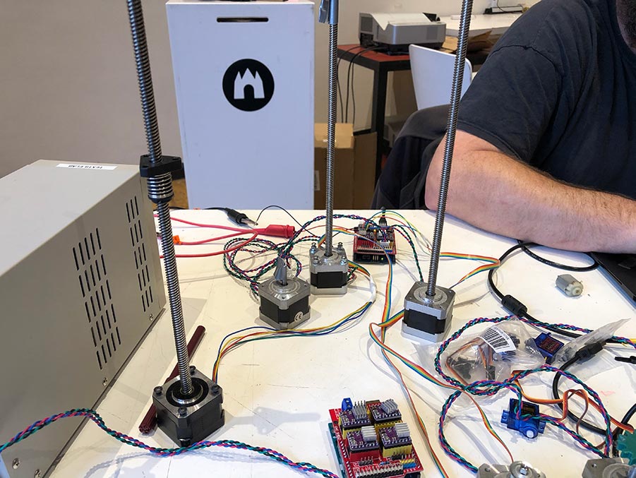
The motor we selected for our project is the stepper motor, type RB 17hdc1220-300n NEMA. An example project of a previous group project with a stepper motor can be found here. Below is a diagram of the Arduino CNC shield.
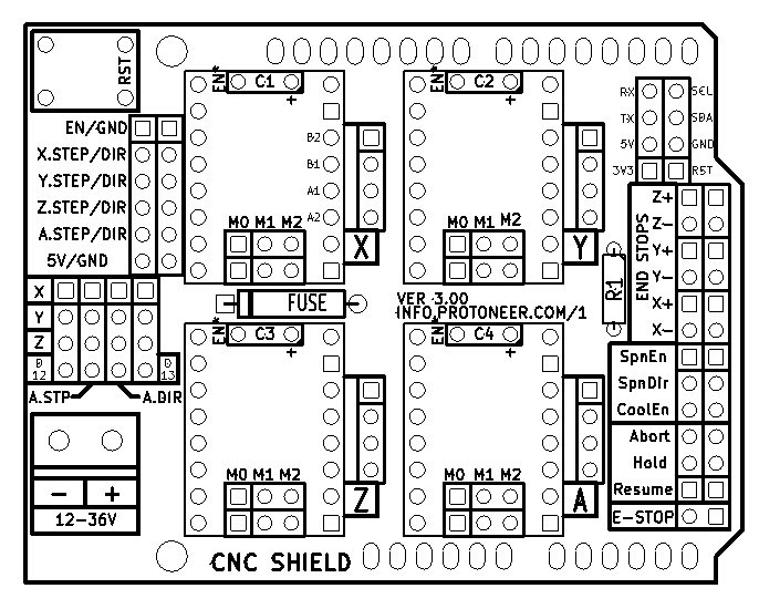
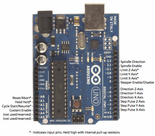
And the positions of the pins on the Arduino:
Next, I consulted the data sheet of the NEMA17 stepper motor.
Programming the stepper motor
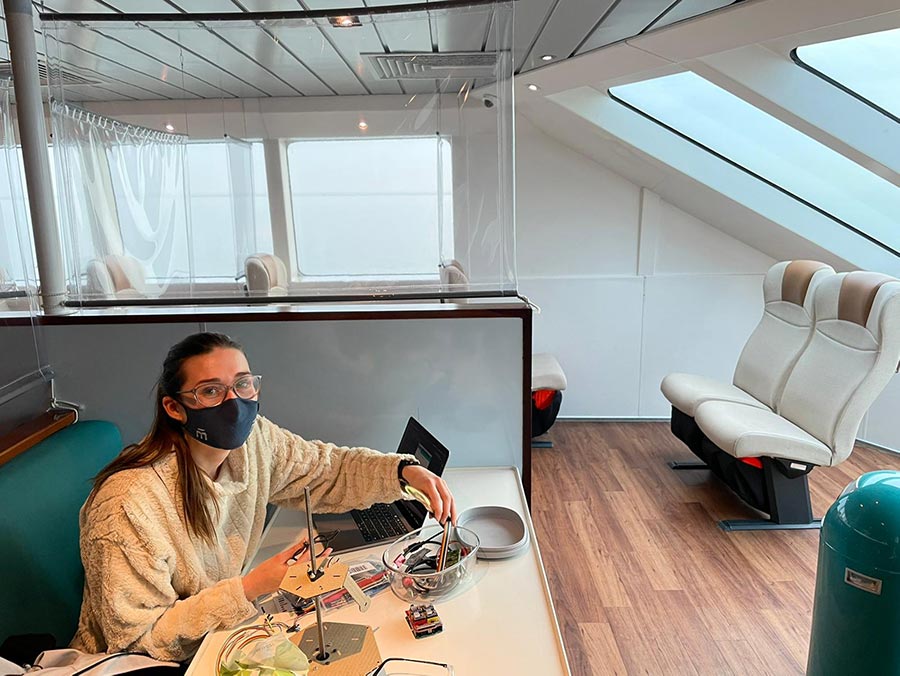
At the beginning of Fab Academy Nadieh and I noticed a break in the schedule, so we both planned a small getaway with our partners. In our planning for machine week we both front-loaded our tasks to have a couple of days off. However, after the first week it became clear that we wouldn’t be able to finish the project if we wouldn’t work on it during the ‘break’. In my case because I had a serious migraine that lasted for four days, delaying my work on the motor tremendously. So this is me trying to get the motor to work on the ferry.
Guidance for testing unipolar or bipolar stepper motors can be found in this Arduino Stepper Library. I followed Arduino’s one step at a time tutorial to test if the wiring is correct. This is the code:
/*
 Stepper Motor Control - one step at a time

 This program drives a unipolar or bipolar stepper motor.
 The motor is attached to digital pins 8 - 11 of the Arduino.

 The motor will step one step at a time, very slowly.  You can use this to
 test that you've got the four wires of your stepper wired to the correct
 pins. If wired correctly, all steps should be in the same direction.

 Use this also to count the number of steps per revolution of your motor,
 if you don't know it.  Then plug that number into the oneRevolution
 example to see if you got it right.

 Created 30 Nov. 2009
 by Tom Igoe

 */

#include <Stepper.h>

const int stepsPerRevolution = 200;  // change this to fit the number of steps per revolution
// for your motor

// initialize the stepper library on pins 8 through 11:
Stepper myStepper(stepsPerRevolution, 8, 9, 10, 11);

int stepCount = 0;         // number of steps the motor has taken

void setup() {
  // initialize the serial port:
  Serial.begin(9600);
}

void loop() {
  // step one step:
  myStepper.step(1);
  Serial.print("steps:");
  Serial.println(stepCount);
  stepCount++;
  delay(500);
}
Nothing happened. So I checked if the stepsPerRevolution were set correctly with this resource. Steps per revolution:
NEMA 17 is a hybrid stepping motor with a 1.8° step angle (200 steps/revolution). Each phase draws 1.2 A at 4 V, allowing for a holding torque of 3.2 kg-cm. NEMA 17 Stepper motor is generally used in Printers, CNC machines and Laser Cutters.
That should be correct. However, the motor didn’t do a single thing. It turned out that it needs to be powered with a 12V external power supply. Which I didn’t have, obviously! After a long search on the island we finally found something, and bought a 12V scooter battery. I proudly presented my solution to the group but Henk discouraged me to use it, because it wouldn’t be safe. He recommended work with a benchtop power supply instead. And that’s only available at Waag. In the meantime, my migraine became worse and worse and he recommended to take some much-needed rest instead. With pain in my heart I communicated this to the group and Nadieh ended up finishing the motor. I still feel bad about not being able to finish this part because obviously I didn’t want to let my groupmates down and I was very excited to learn about programming a motor.
Final design
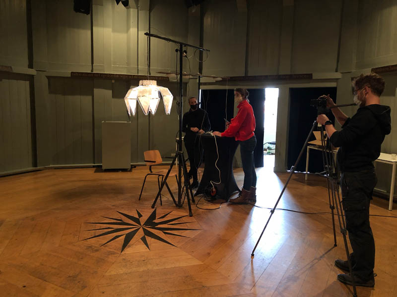
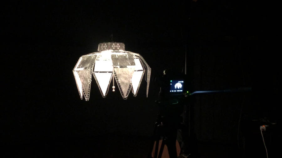
Here are some pictures of us bringing it all together in preparation for the review. Douwe in action behind the camera, he made a beautiful video.
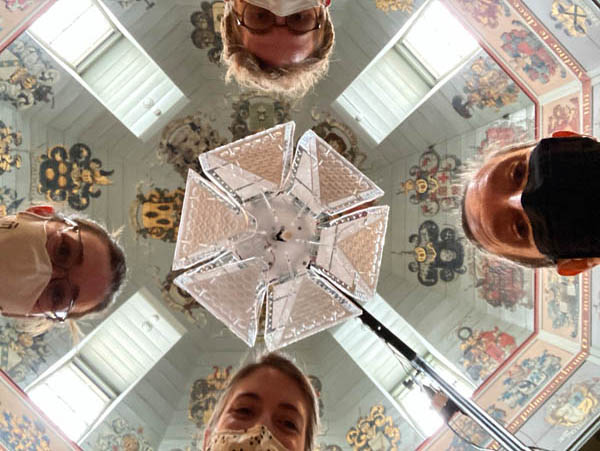
The magical moment when you look at the lamp from below. The contrast with the ceiling at Waag is fantastic.
Want to see more of the project? Here you can find our group page.
What went wrong and how did I solve it
This was a busy week! In the schedule, it said ‘break’, so we went on a mini-holiday to the Dutch island of Vlieland. Therefore, I decided to add gitlab to my laptop in addition to the desktop pc. I ran into a couple of problems, in the section below you can see how they were solved.
1. Repo size
It’s my turn this week! After a long night during machine week, I was tired and forgot about the maximum file size. There is a 10MB cap per push for our GitLab repository. So far, I’ve been able to keep within those limits. To fix this, Henk referred to Paula’s documentation.
Downloaded Homebrew with the following command:
/bin/bash -c "$(curl -fsSL https://raw.githubusercontent.com/Homebrew/install/HEAD/install.sh)
Then I downloaded NCDU, NCurses Disk Usage.
brew install ncdu
Navigate to the folder and enter:
ncdu
This shows the git size. It turned out that my .git file exceeds the limits. I used this manual to navigate. The q key allows you to quit and exit ncdu.
.git size went down from 147.1 MB to 67.3 MB. This is still too big.
Then I continued with the second step in the documentation. This reduced the file size, but still the commit wasn’t able to be pushed to git. I asked Henk for help and it was solved within 5 minutes.
cd your-repo-folder
ls
mv your-repo-folder your-repo-folder.bak
Next, go to GitLab and clone your SSH key.
git clone git@gitlab.fabcloud.org://///
Then open one page or post of your repo locally, and make a small change. I added the word ‘Test’ to one file. Save it, go back to terminal, type git add . then git commit -m "test" and git push. This solved the problem!
Now you can manually re-add the lost items.
2. Motor
I was supposed to do the hardware and software of the stepper motor. Due to the break, I was not in Amsterdam. I brought a small prototype and motor, however the 12V power supply was missing. On the island, we searched and searched. Eventually we found a power supply for a scooter. Henk didn’t recommend it, because you can’t control the voltage. So there was no power supply… :(
3. 3D print too big
As written above, the first model I designed for covering the wires was too big for the 3D printer. I solved this by creating a 2D design and lasercut it instead.
Downloads
Explore more like this
Week 17 Invention, Intellectual Property and Business Models
After acing through the technical assignments of Fab Academy, the last two weeks have a lighter load so we can focus on the final project. But this does not mean...
Week 16 Applications and Implications
Propose a final project masterpiece that integrates the range of units covered, answering: