7. Computer Controlled Machining (CNC)
Overview
This week was all about Computer Controlled Machining (CNC) — getting to understand how a digital design turns into a real, physical object cut by a machine that follows nothing but code.
During this week I learned what a CNC milling machine actually is and how it works, the complete CNC workflow from CAD file to finished part, the role of Aspire 9.5 in generating toolpaths, the role of UGS CNC (open-source software) in talking to the machine, the importance of machine axes, cutting tools, feeds and speeds, and — most importantly — the safety rules around CNC machines.
Safety was something I paid extra attention to, mostly because my final project is also a safety system, so thinking carefully about risk and protection felt very close to home this week.
Group Assignment
Our group assignment was carried out together with my classmate Ani Petrosyan, and at Fab Lab Gyumri together with instructors Rudolf Igityan and Mkhitar Evoyan. As a group we went through the CNC fundamentals, safety procedures, and machine workflow together, then tested it on the OLSK CNC at Fab Lab Gyumri. For more details, you can check out the full group assignment page.
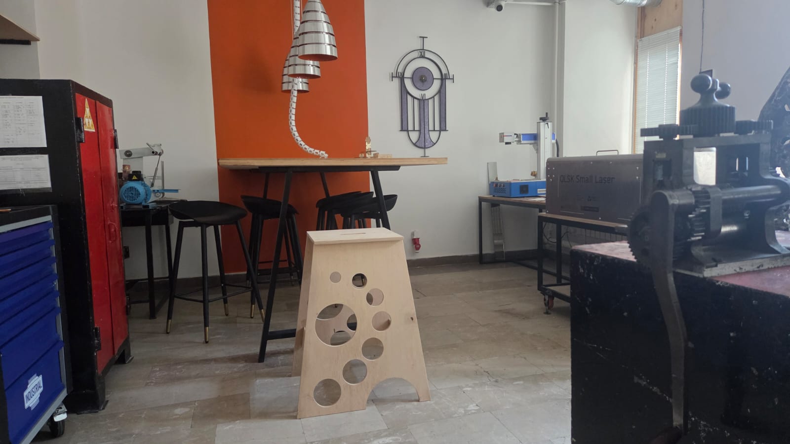
The Machine
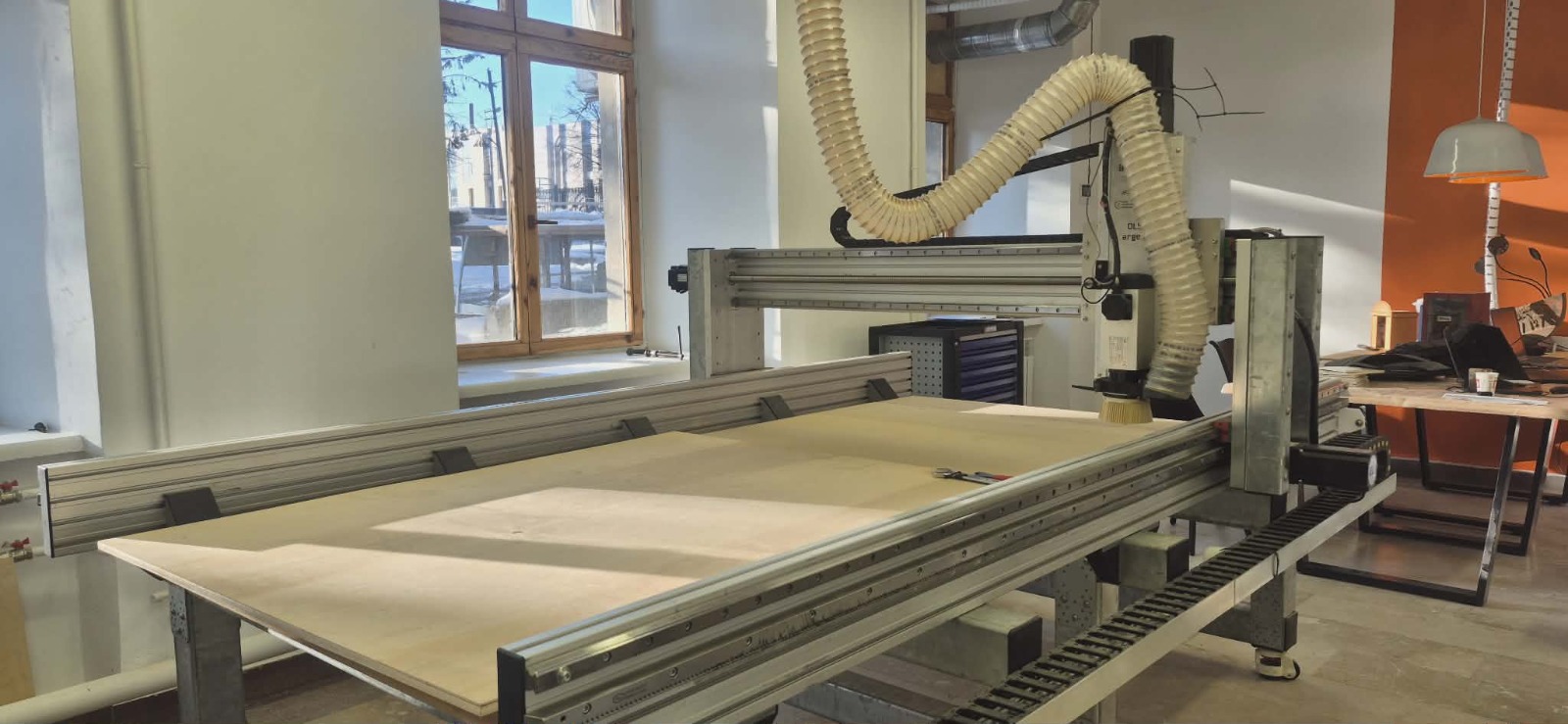
For this assignment we used the OLSK Large CNC V1, the large format CNC mill available at Fab Lab Gyumri — an open source design by Daniele Ingrassia of InMachines Ingrassia GmbH, part of the Open Lab Starter Kit (OLSK) family of open source digital fabrication machines.
Specs of the machine: milling volume 2500 × 1250 × 300 mm, a frame combining steel pipes with CNC-milled solid aluminum profiles, 25 mm ball screws with rack and pinion motion, 25 mm linear rail guides, NEMA 34 stepper motors, air-cooled spindle, inductive homing sensors, and 220V power.
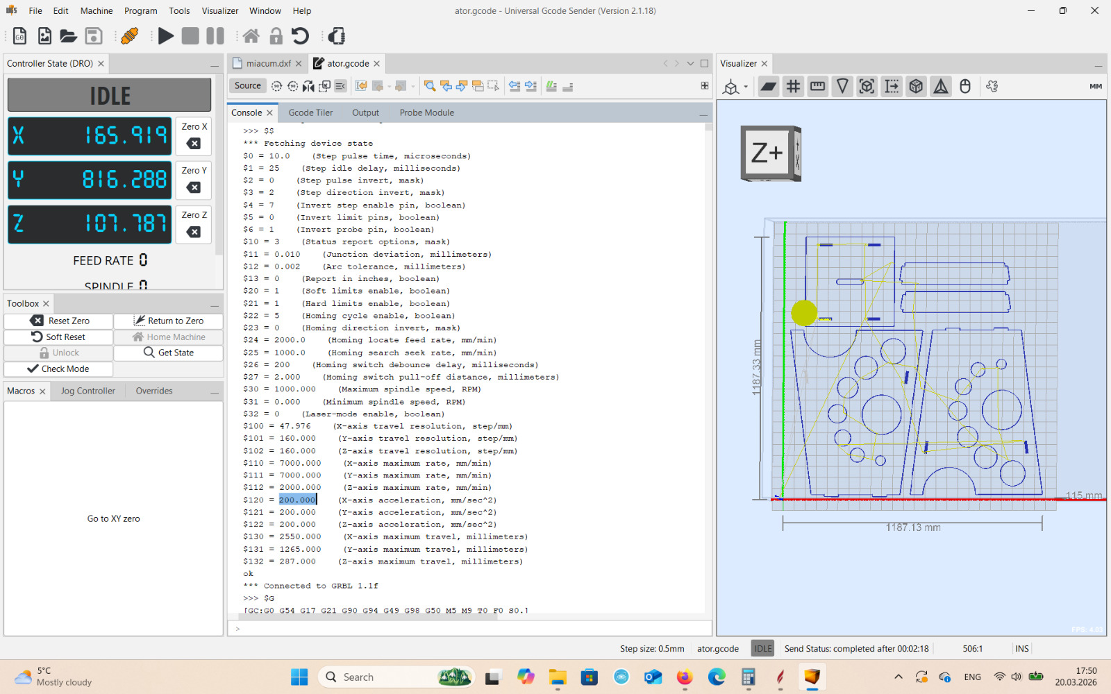
The machine moves along three axes — X (left/right), Y (front/back), Z (up/down) — and we controlled it with Universal G-code Sender (UGS), an open-source program that sends G-code to the machine, lets you jog the axes manually, and shows job progress in real time.
Safety Rules
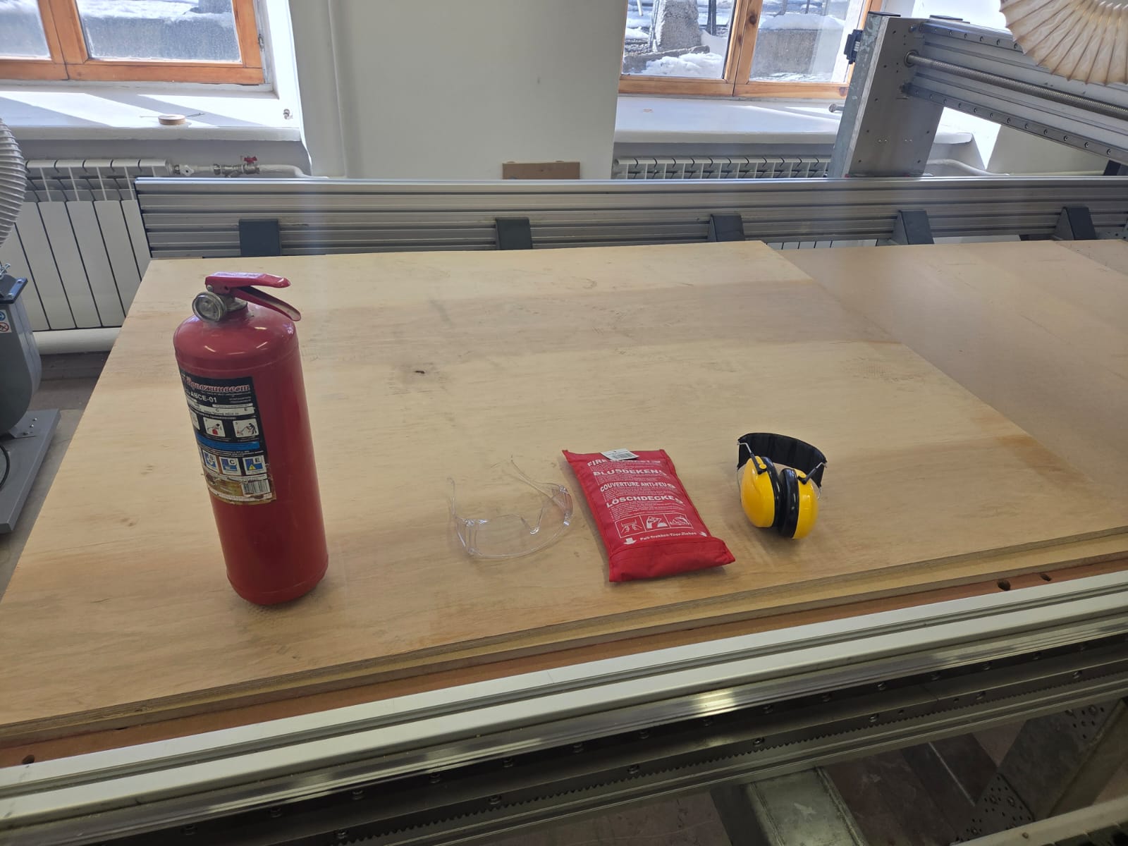
These safety rules were clearly explained by the instructors at Fab Lab Dilijan during the Fab Academy program, and honestly, after seeing how powerful these machines are, none of them felt like overkill. A CNC machine moves fast, spins hard, and doesn’t know the difference between wood and a careless hand, so before anyone touches the machine, the basics have to be second nature.
Personal protective equipment: wear safety glasses, tie long hair back, avoid loose clothing, remove jewelry.
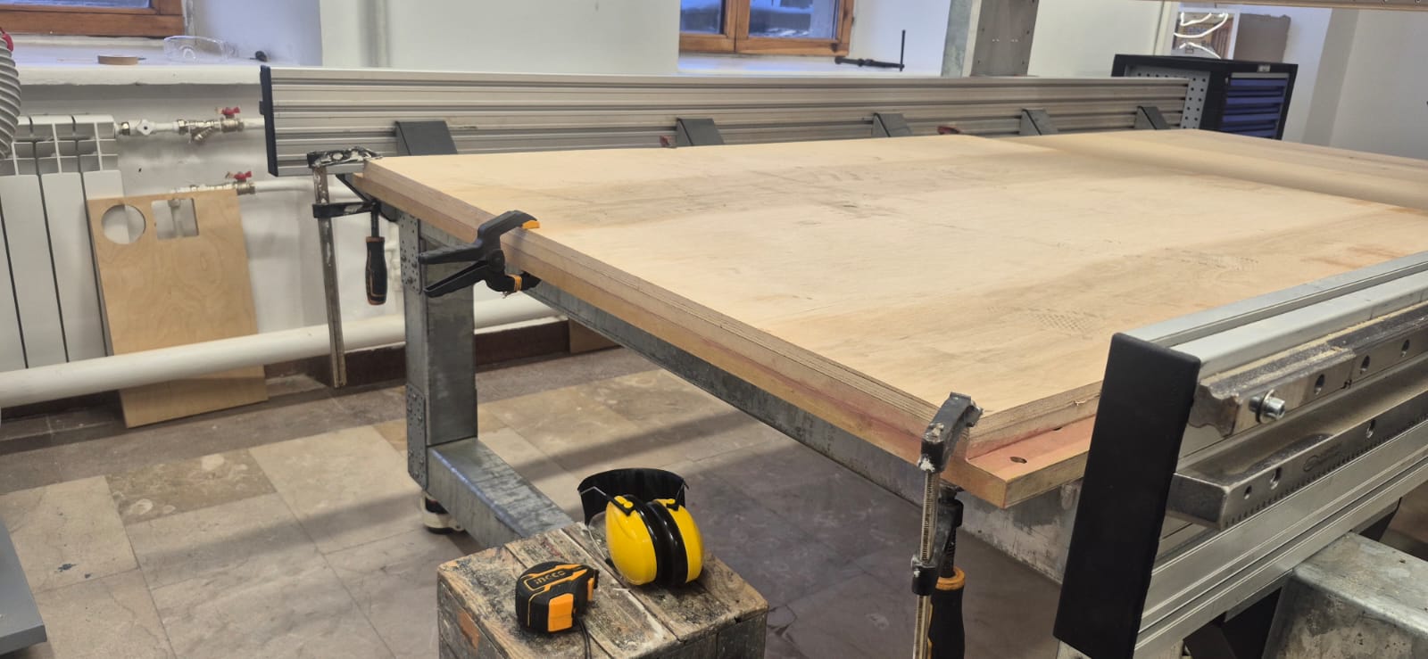
Material fixing: the material has to be firmly fixed using clamps or screws before the spindle ever turns on — a loose piece of wood at high spindle speed is not something you want to find out the hard way.
Tool check: before machining starts, the tool itself needs to be checked — properly seated, properly tightened, and the right tool for the job.
Emergency stop: always know exactly where the Emergency Stop button is before you start — you don’t want to be looking for it once something goes wrong.
What is a CNC Milling Machine
A CNC milling machine (Computer Numerical Control) is a computer-controlled fabrication machine used for cutting and shaping materials with high precision. Instead of a person guiding the cutting head by hand, the machine follows instructions written in G-code — a list of exact coordinates and movements that tells the spindle where to go, how fast, and how deep. Material is removed using a rotating cutting tool called an end mill, which physically carves the shape out of the stock material, layer by layer if needed.
CNC milling machines can process a wide range of materials, including wood, plywood, MDF, plastics, foam, and aluminum. What makes CNC machining genuinely useful in a fab lab context is that it’s accurate and repeatable — once the toolpath is right, you can cut the same part ten times and get the same result ten times, something that’s basically impossible by hand.
Once that geometry is set, CAM software turns it into an actual cutting path for the tool to follow:
CNC Workflow
The whole process, from idea to finished part, follows a clear chain: FreeCAD → Aspire 9.5 → G-code → UGS CNC → CNC Milling.
Everything starts with a digital design, built in CAD software, where the actual geometry of the part gets defined. Once the design is ready, it gets imported into CAM software, where the toolpaths are generated — the path the cutting tool will physically follow — based on parameters like cutting depth, feed rate, spindle speed, and tool selection. After the toolpath is set, the CAM software translates everything into G-code, the actual instructions the machine will read.
The G-code file then gets sent to the machine using UGS CNC, which handles the communication between the computer and the CNC.
CNC Software
This week we worked with two important programs.
Aspire 9.5 (also known as VCarve) is the software we used to prepare machining operations and generate toolpaths from the design. With Aspire we can define material thickness, select the cutting tool, set feed rate and spindle speed, generate toolpaths, and export G-code.
UGS CNC (Universal G-code Sender) is an open-source program used to communicate with CNC machines — the bridge between the G-code file and the physical motors. With UGS we can send G-code to the machine, control axis movement manually, monitor the job in real time, and start or stop machining.
Cutting Tools, Feeds and Speeds
CNC machines use different cutting tools, generally called end mills, and each one is suited to a different kind of cut: a flat end mill for flat surfaces and general cutting, a ball nose end mill for curved surfaces and 3D machining, a V-bit for engraving, and a compression bit for cutting plywood with clean edges on both the top and bottom surface.
Two parameters that can make or break a job are the feed rate (the speed at which the tool moves through the material) and the spindle speed (how fast the tool itself is spinning). Get these wrong, and the consequences show up fast — tool breakage, burned material, poor surface quality.
Individual Assignment
After learning about CNC machining and going through the safety procedures, I moved on to my individual assignment: designing, milling, and assembling a bar stool.
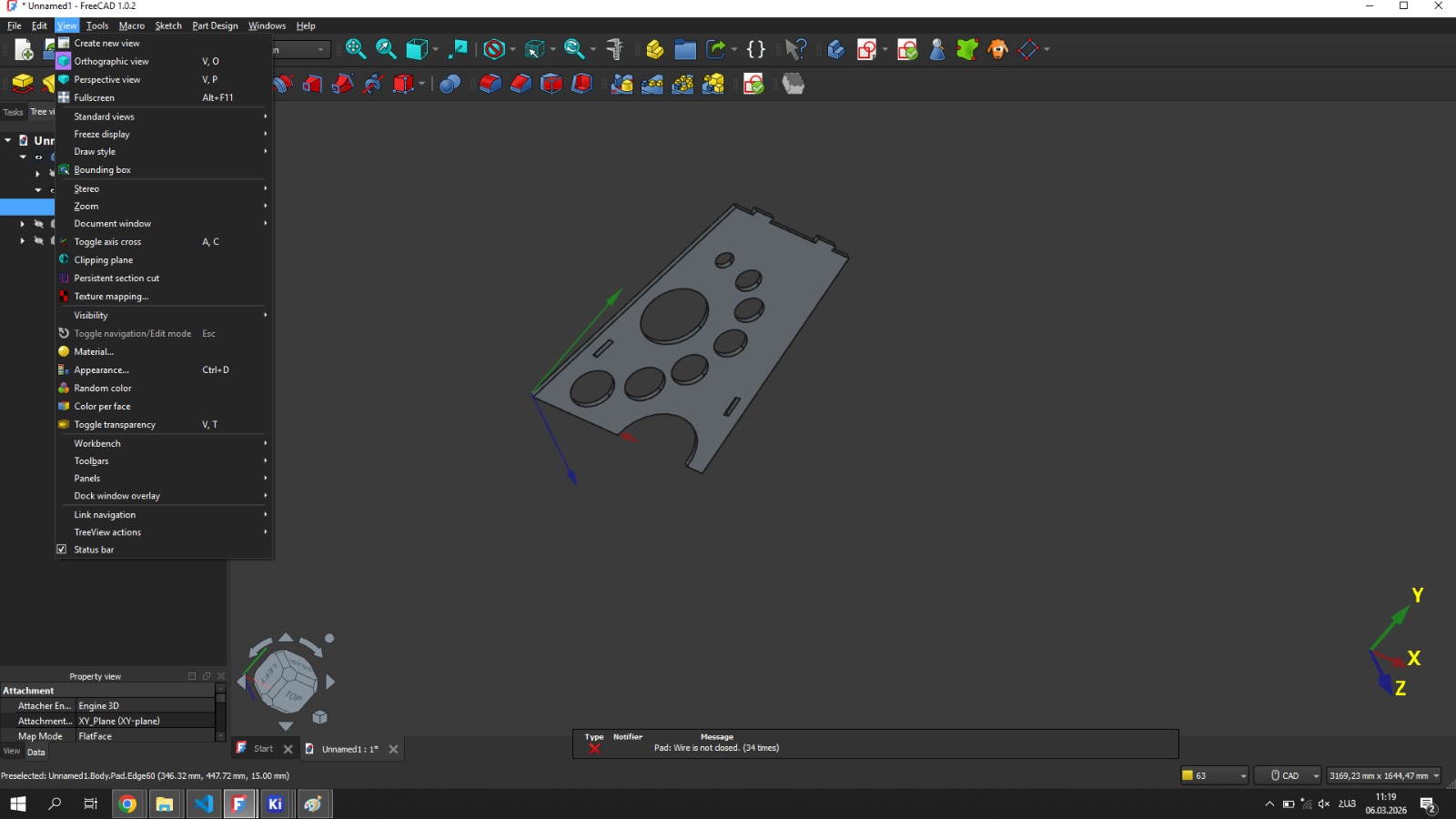
Design in FreeCAD
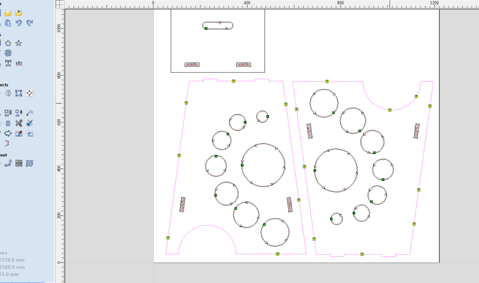
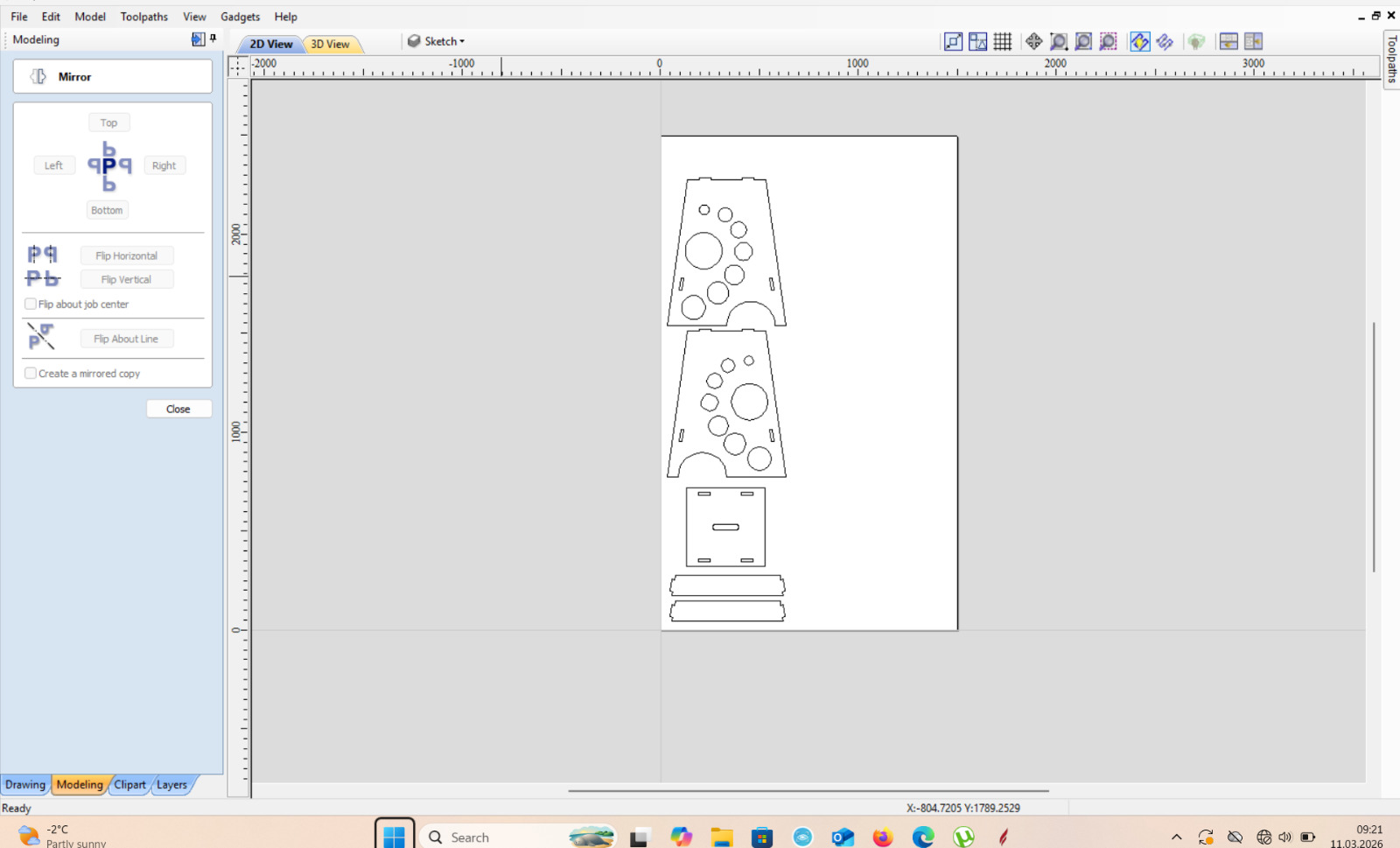
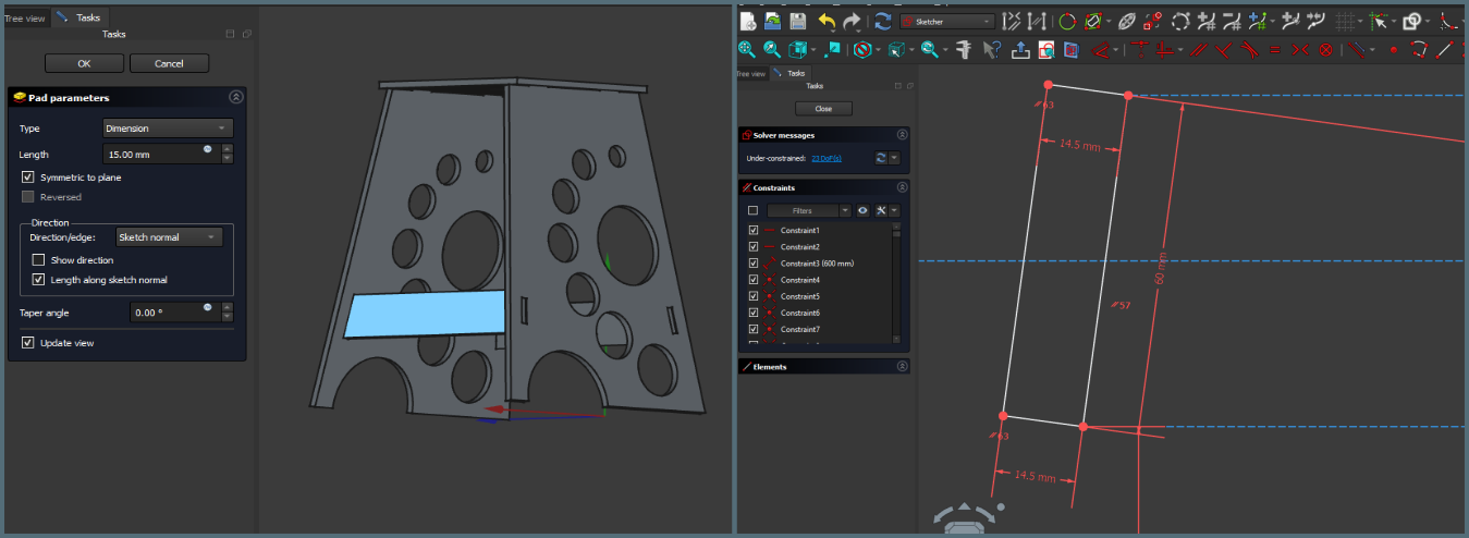
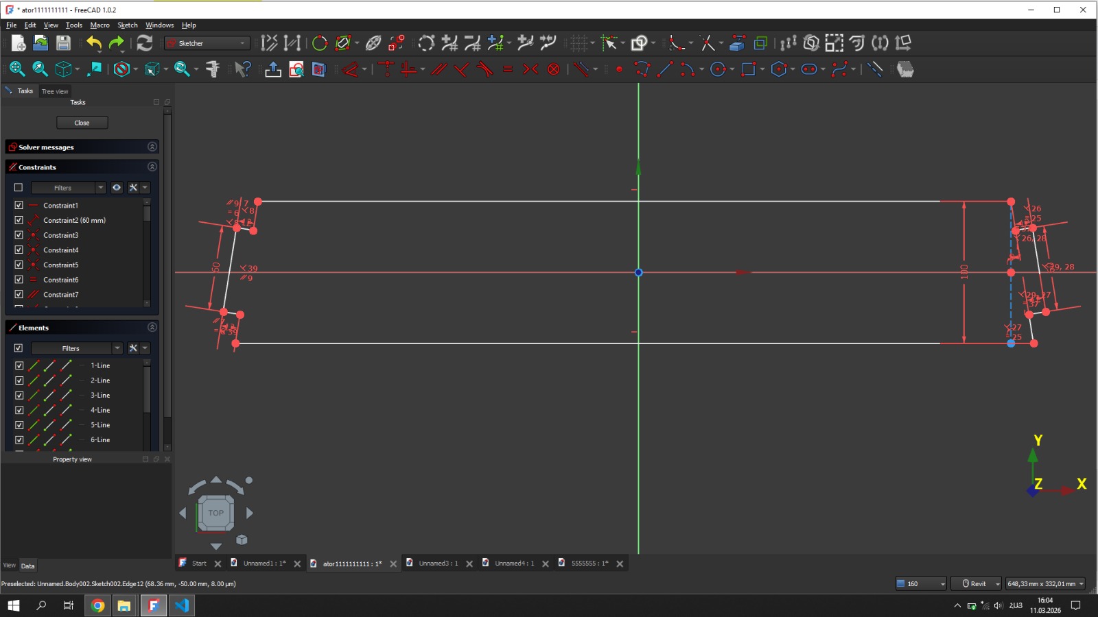
The design was created in FreeCAD using Part Design. The stool consists of fif separate bodies — each one representing an individual part of the structure: the seat, the side panels, and the support elements. Each body was modeled independently using Pad operations based on 2D sketches.
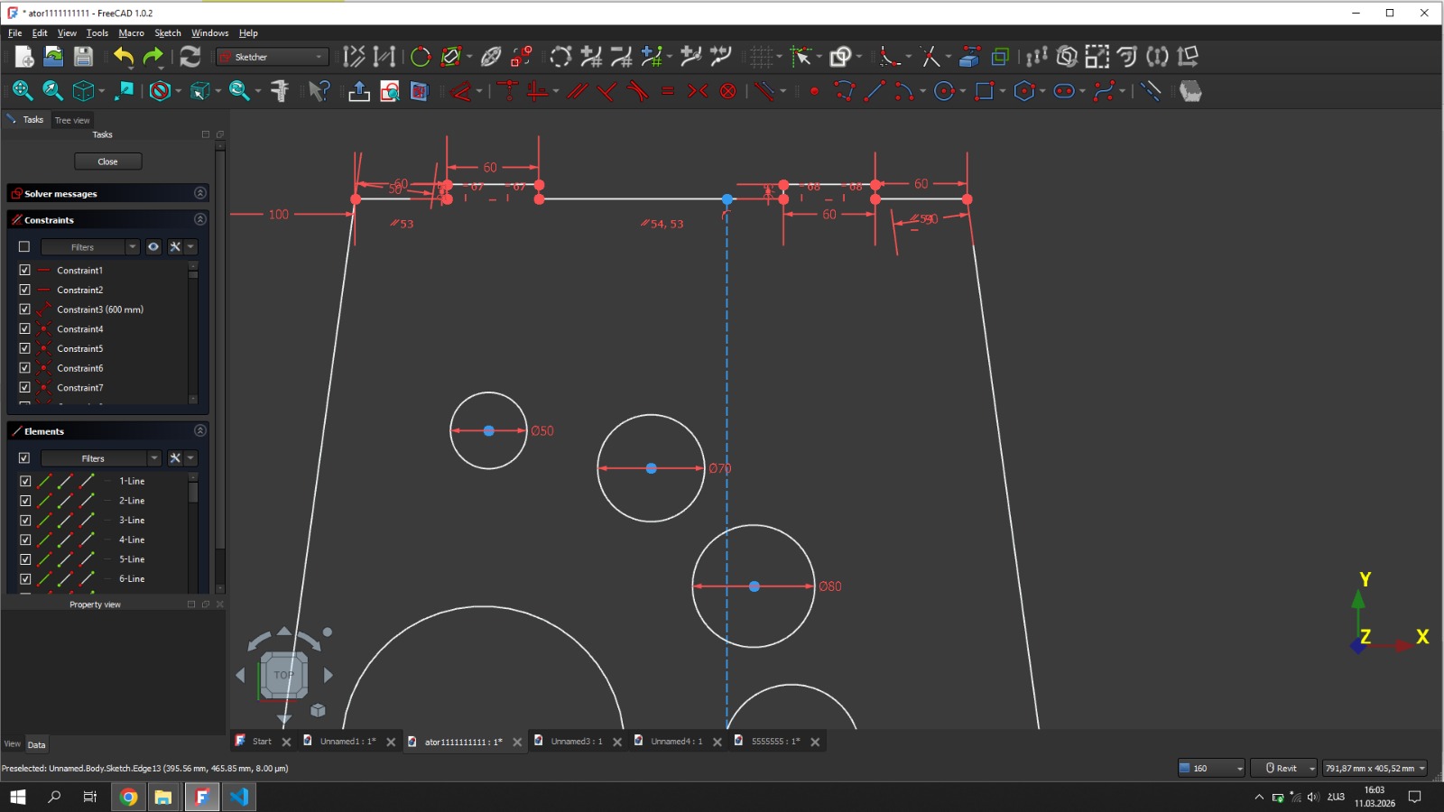
My goal was to design a stool assembled entirely using press-fit joints — no screws, no glue, no extra hardware, just the geometry of the parts holding everything together. The entire construction relies on interlocking slots cut to the exact thickness of the material. This meant the joint dimensions had to be precise, since even a small mismatch would make the parts too loose or too tight to assemble.
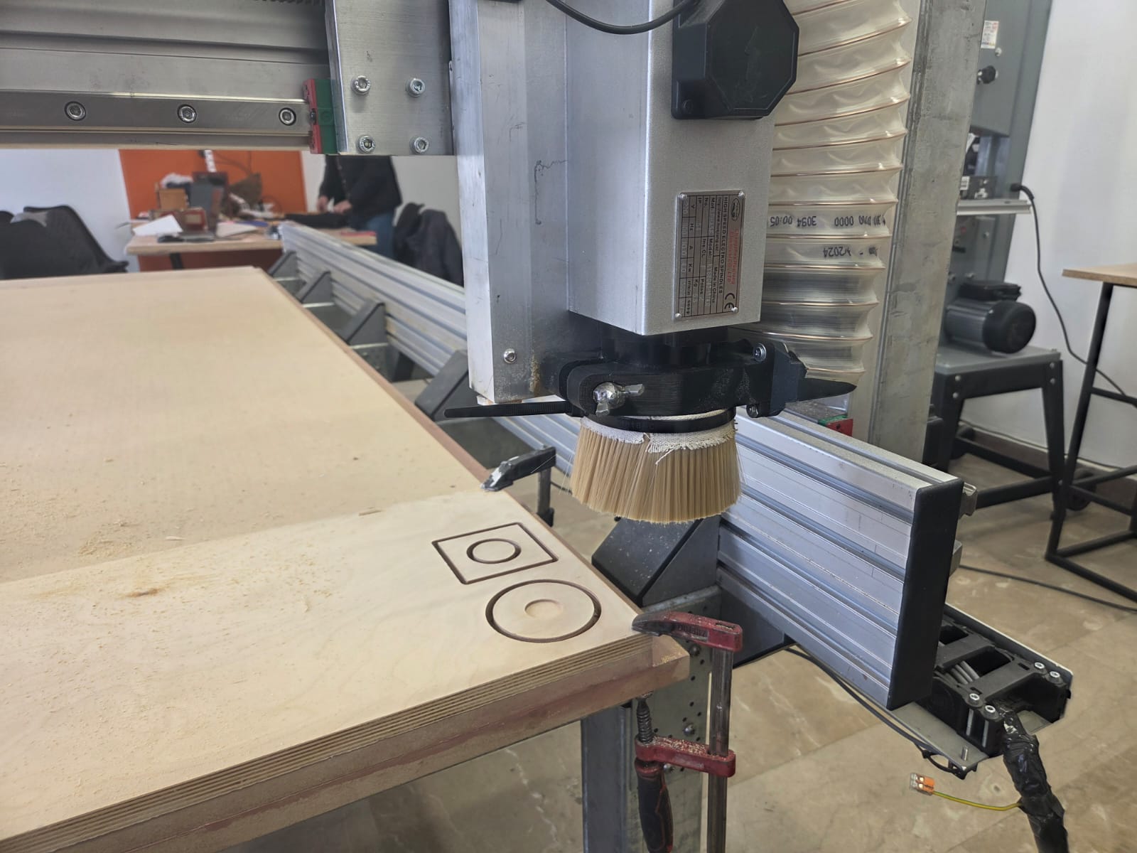
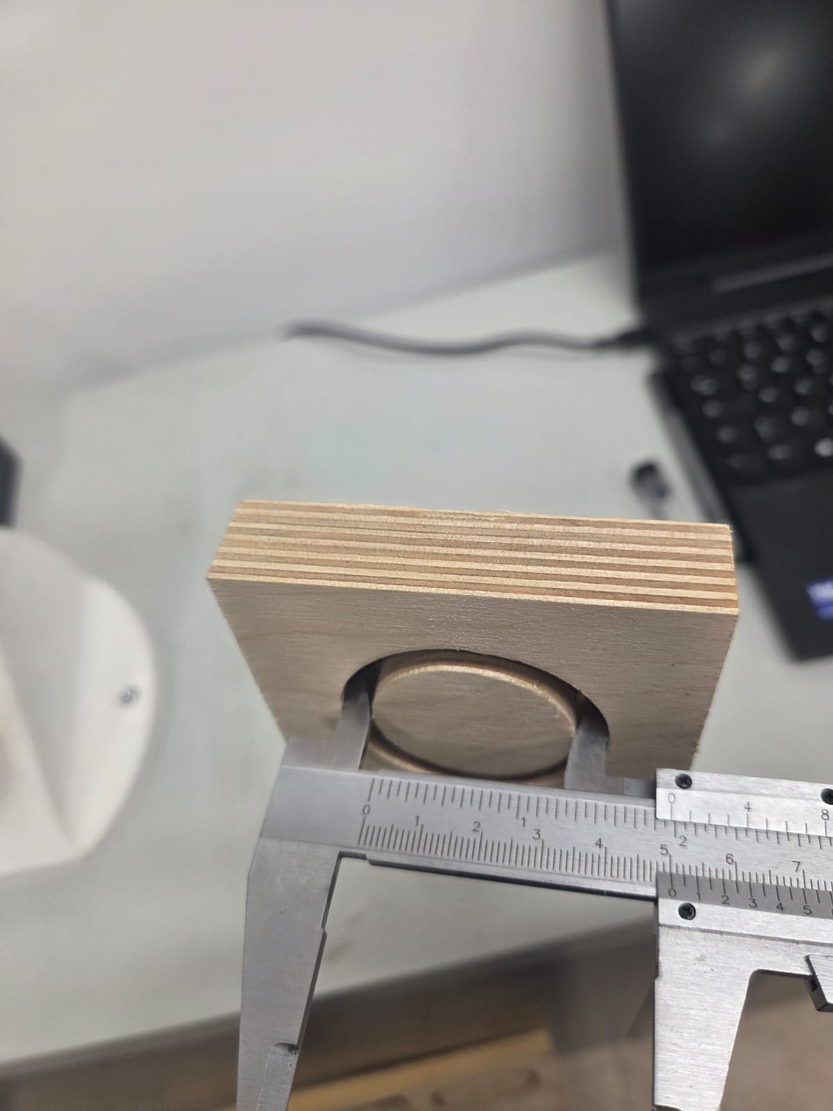
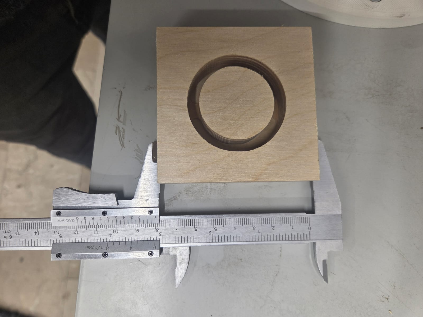
The joint slot width was set to 14.5 mm, while the material thickness is 15 mm — giving a 0.5 mm runout/kerf compensation on each side, based on the value measured during the group assignment.
A closer look at one of the press-fit joints, showing how the slots are sized to the material thickness:
The panels also feature oval and circular cutouts. These serve two purposes — they give the stool a lighter, more open visual character, and they also function as footholds, making it easier for shorter people and children to climb up onto the stool.
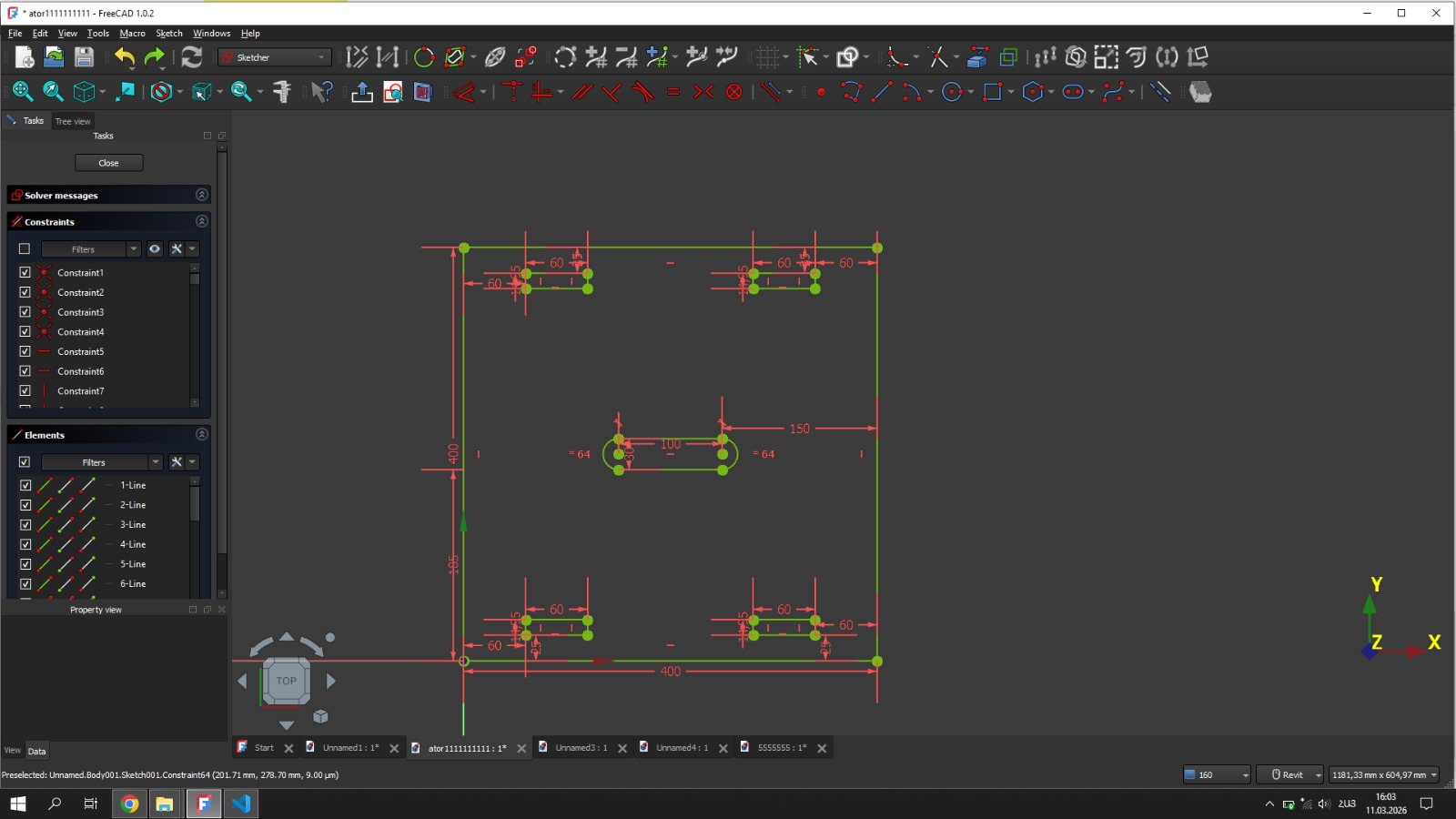
And the finished sketch, ready to be exported for machining:
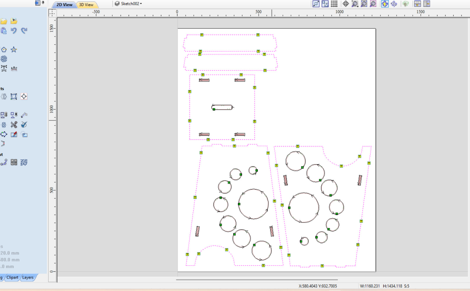
The material used was 15mm birch plywood. The parts were nested on a 1525 × 1220 mm sheet, large enough to fit all of the stool’s pieces in a single pass on the OLSK Large CNC.
It is worth noting that while the press-fit joints are clearly visible in the 3D model and in the cut parts, they are intentionally not visible on the assembled stool. This was a deliberate design decision — I wanted the final product to look clean and continuous, without the joints breaking up the surface visually. The connection is structural, not decorative, so hiding it made sense from a design standpoint.
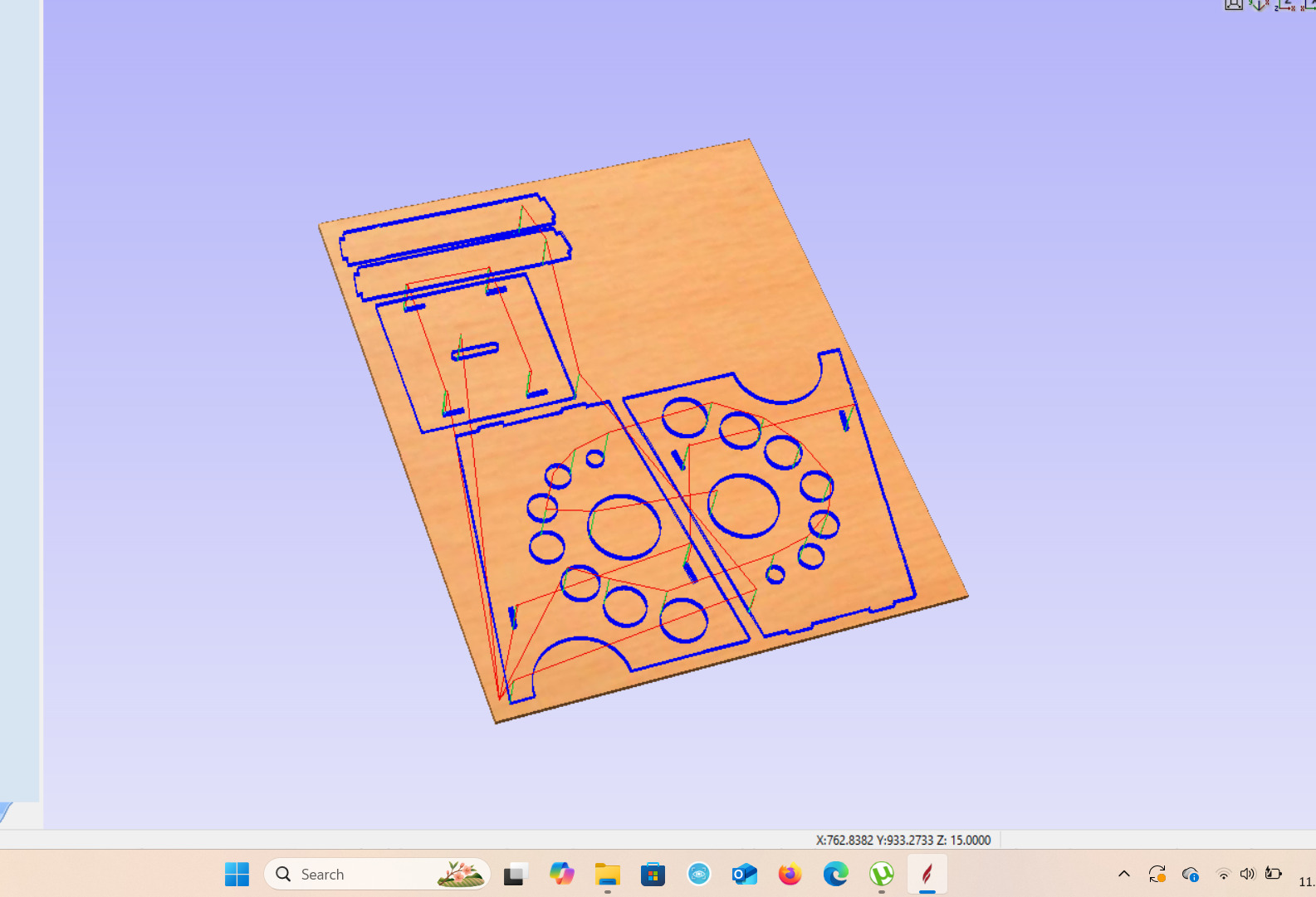
G-code Generation
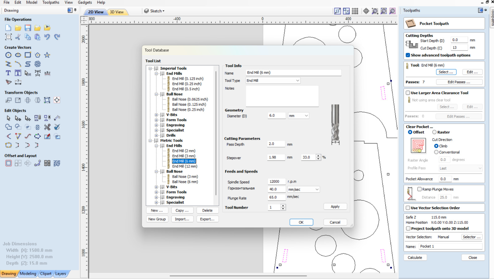
Once the model was finished in FreeCAD, I imported the design into Aspire 9.5, where I defined the material thickness, selected the cutting tool, created the toolpaths, and generated the G-code.
The cutting parameters I used:
| Parameter | Value |
|---|---|
| Tool | End Mill 6 mm |
| Cut Depth | 13 mm |
| Pass Depth | 2.0 mm |
| Passes | 7 |
| Stepover | 1.98 mm (33%) |
| Spindle Speed | 12000 rpm |
| Feed Rate | 40.0 mm/sec |
| Plunge Rate | 65.0 mm/sec |
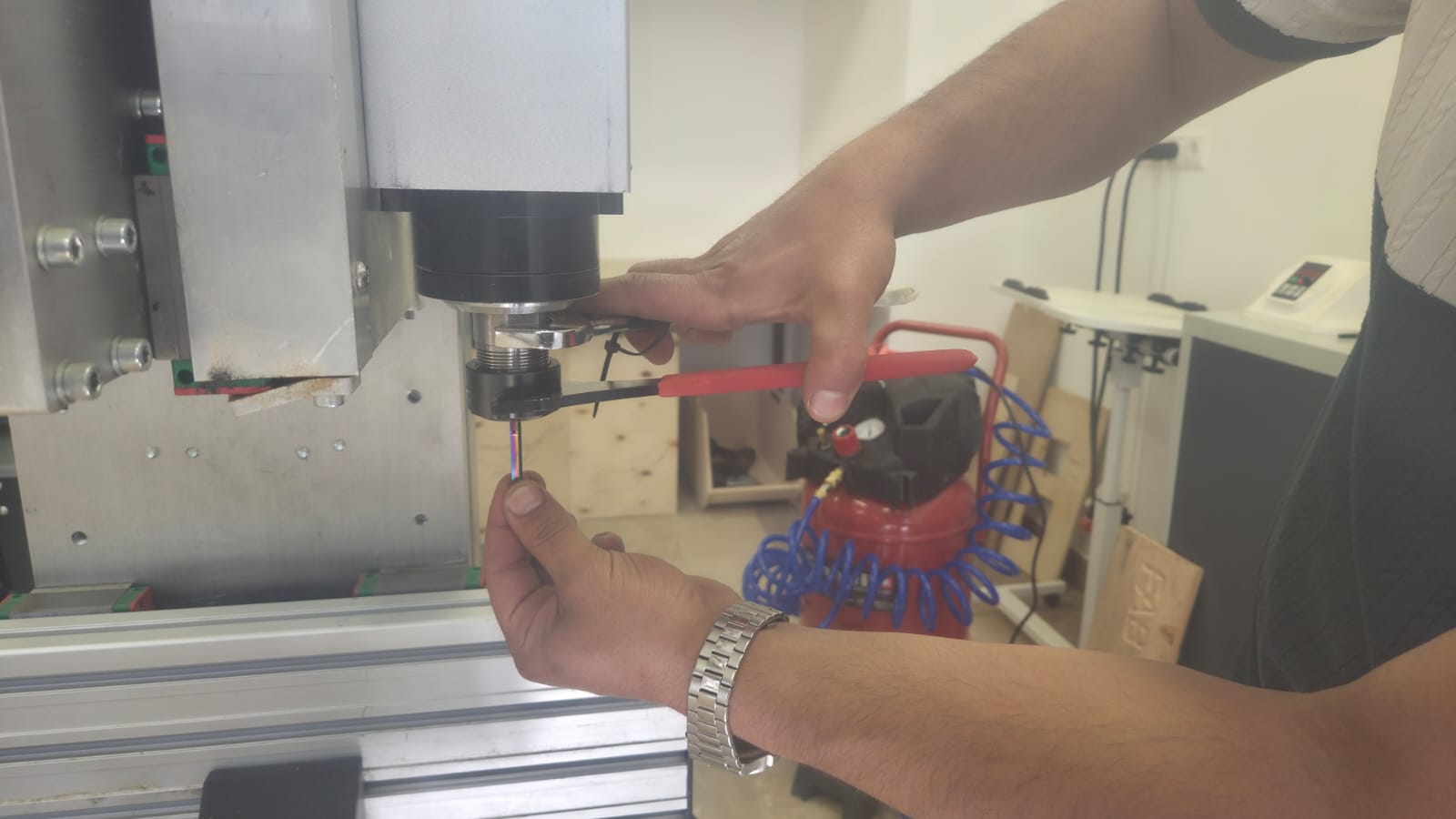
CNC Machine Setup
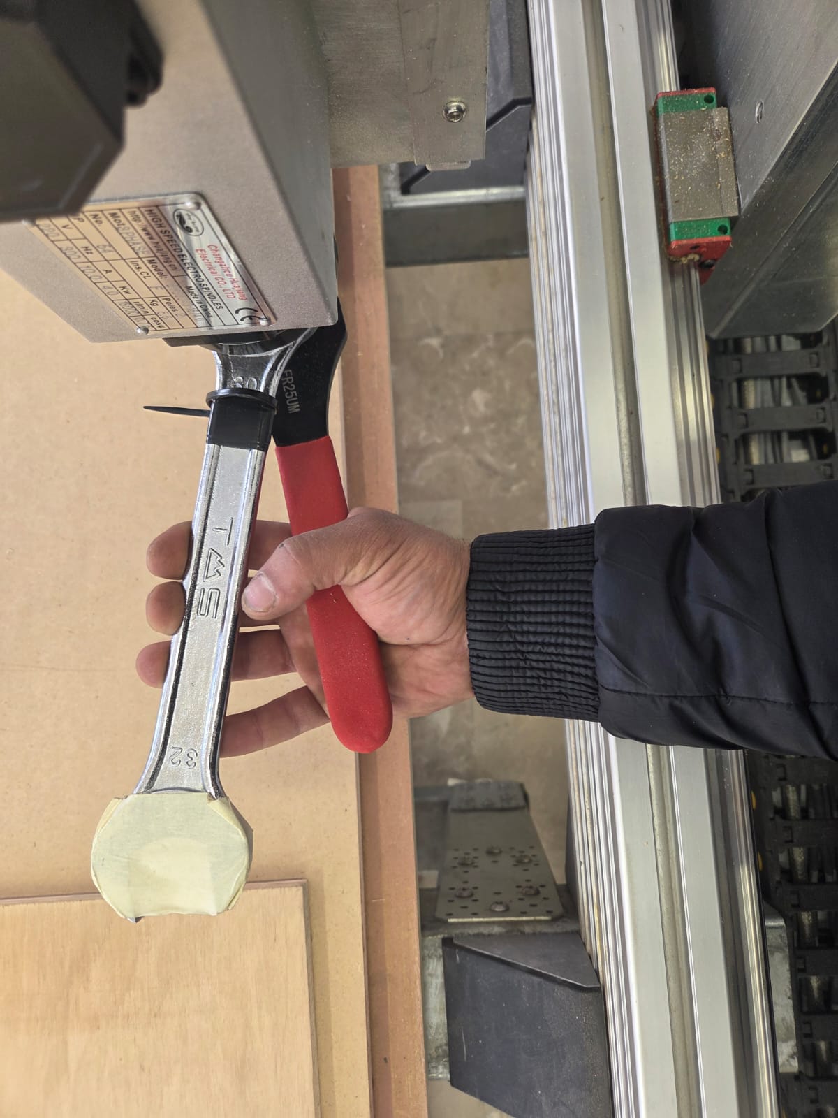
Before starting the actual machining, the machine itself had to be prepared. First, installing the cutting tool:
Then, preparing the machine bed and fixing the material in place:
And finally, setting the X, Y, Z origin so the machine knows exactly where to start cutting:
Milling Process
Once setup was complete, the G-code was loaded into UGS CNC and the machining process began.
Problems and Solutions
The machining process itself went smoothly, but the material caused an unexpected problem. The plywood looked good from the outside, but once the CNC started cutting, it became clear the internal quality wasn’t what it appeared to be — the layers began separating along the cut edges. The only solution was to glue the layers back together and clamp them until the adhesive set before continuing with assembly. This was a reminder that material quality matters as much as the design and the machining — even a well-prepared toolpath can’t compensate for delaminating plywood.
Post-Processing and Assembly
After the CNC finished cutting, the parts needed some cleanup before assembly. I removed the tabs holding each piece to the sheet, sanded the cut edges to remove any roughness from the milling process, and checked that each joint slot was clean and free of wood fibers.
Assembly was straightforward — the press-fit joints clicked together without any screws, glue, or additional fasteners. Each slot fit snugly into its matching tab, holding the structure together through friction alone.
Final Result
After machining and resolving the delamination issue, the stool parts clicked together through the press-fit joints without a single screw or additional fastener.
Learning Outcome
During this week I learned CNC machine fundamentals, the digital fabrication workflow from design to physical part, Aspire 9.5 toolpath generation, UGS CNC machine control, cutting tools and machining parameters, and CNC safety procedures — both individually and on a much larger machine in Gyumri.
This week helped me understand CNC machining as a complete digital fabrication process connecting design, software, machine control, and physical manufacturing — and seeing both a small-scale and a large-format machine in the same week made it clear how much these principles scale, even when the hardware looks completely different.