7. Computer controlled machining
Dilijan lab
Safety training
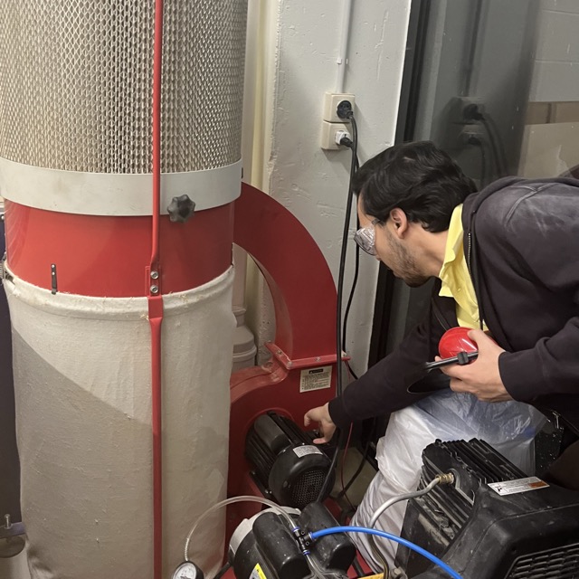
Key points to note: - Verify clearance of tool path before cutting - Ensure that the collet is in good condition and the bit is fully inserted - Ensure continuous air filtration, and dust vacuuming (dust accumulating is a fire hazard) - Eye and ear protection! Debris can come flying unexpectedly, whereas continuous noise can result in permanent hearing loss.
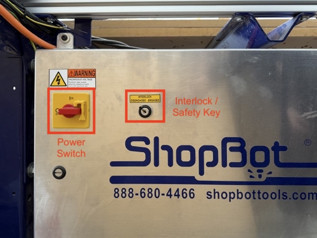
After having these considered we proceeded with machine kill-switch operations.
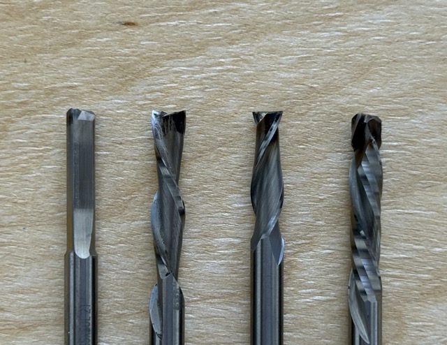
Types of bits
Bits come in various shapes and sizes, and from the first glance they can all seem the same. But it’s simpler than it seems: there are drill, and mills. Drill bits are desined to make holes – vertical cuts, and mills cut sideways, making horizontal cuts.
The grooves on the bits can vary also: clockwises, anti-clockwise, bidirectional. When changing the bits, you should first consider the side of the plywood in order to have smooth finishing. With drill bits being upcut, downcut, bidirectional. Selecting the appropriate bit for the material and application is essential. Using incorrect tooling can cause excessive friction, elevating temperatures to ignition points. Accumulated wood dust and shavings are highly combustible and can catch on fire.
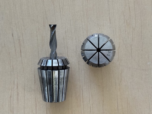
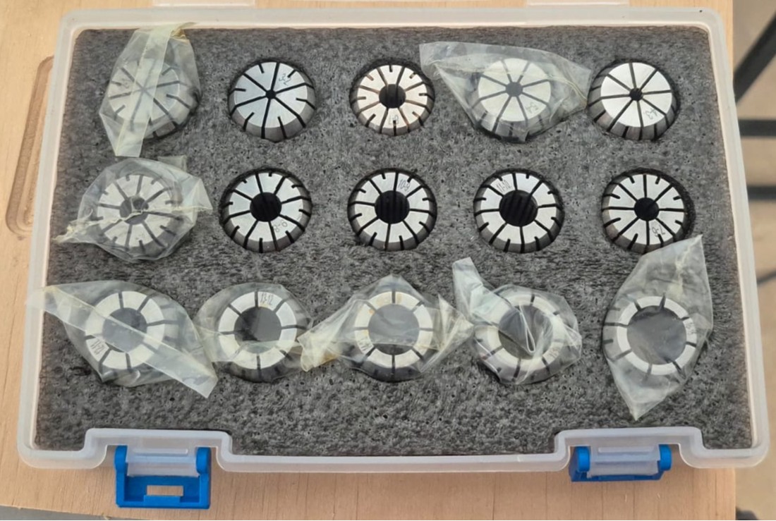
To attach the bits onto the CNC machine we use collets, a sleeve put around spindle and tightened so as to grip it. And just like drill bits and end mills, collets come in different sizes, to ensure compatible fit with bit diameter.
And here is the collet:
Machine calibration
First, if changing the end mill, you need a pair of spanners. In our shop, the one which has teeth to grip on the spindle, is attached on the power block’s keys. After changing the mill you must clean the collet with compressed air.
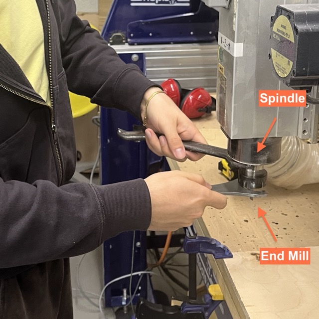

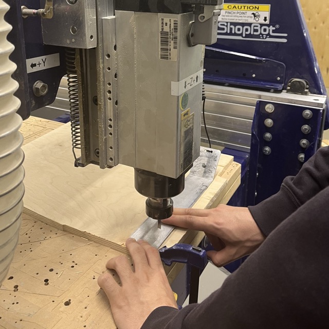
After having the mill bit fastened you should take out the aluminum plate and the crocodile clip to level the Z-axis. You should hold the plate down tightly, once the leveling begins, the mill lowers slowely and takes two samples. Finally, you should turn on the vacuum.
Securing workpieces
It is important to have the material tightly secured onto the cutting bed, also called sacrifice layer. For edges we used quick action clamps. Whereas for areas that are not reachable by clamps, we use screws and simple wood scraps. The first scrap piece should match the thickness of the material being cut, and is placed beside it. The second scrap piece is then laid across both — bridging the material and the first scrap, and is fastened down with a screw into the bed, clamping the material in place.
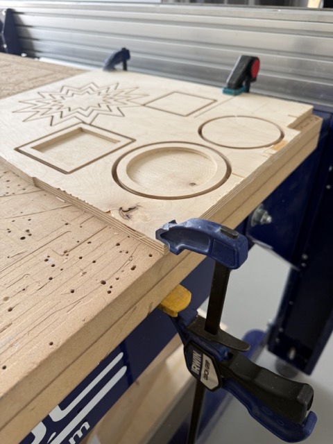
Whereas for areas that are not reachable by clamps, we use screws and simple wood scraps.
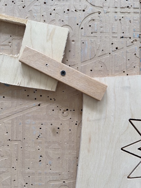
The first scrap piece should match the thickness of the material being cut, and is placed beside it. The second scrap piece is then laid across both — bridging the material and the first scrap, and is fastened down with a screw into the bed, clamping the material in place.
To run the machine: Press the red button > Turn the key to engage the spindle > Set the zero point > Turn on the vacuum & filtration > Submit the file > Turn on the spindle
Tests
Test 1
As a first test we made square and circle shaped pockets, then matching-size cutouts to see if they fit into one another. So not only had we used two cutting methods, but also placed dogbones and tabs to ensure accurate fit.
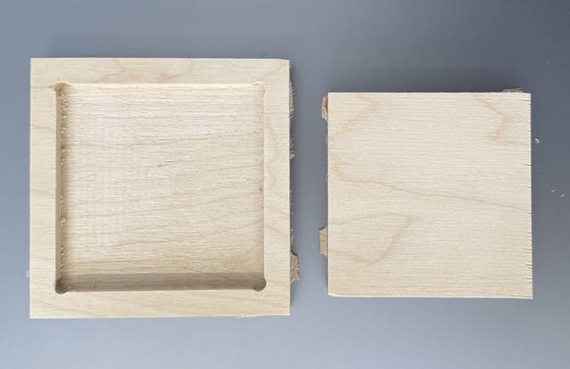
Dogbone: a small round cutout at inside corners for square parts to fit properly
Tab: a small bridge of uncut material that holds the workpiece in place during cutting
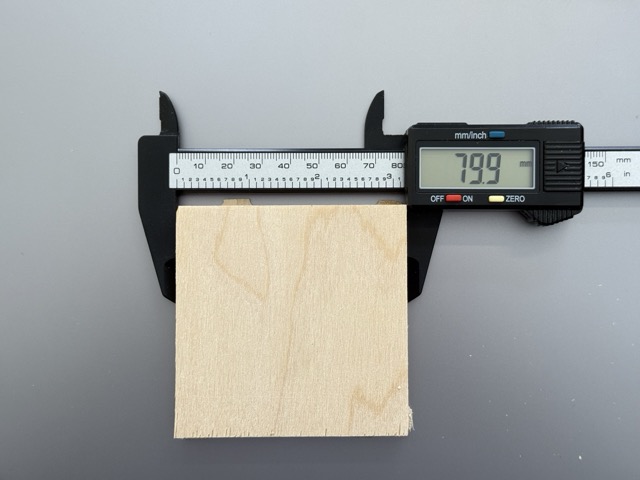
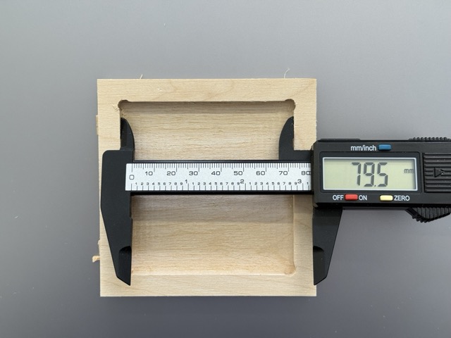
The test did not go as planned. The pieces did not fit together. We used a vernier caliper, and the numbers spoke for themselves. The pocket was too small by 0.4 mm.
Gyumri lab
The group assignment was conducted by instructors Rudolf Igityan and Mkhitar Evoyan together with students Ani Petrosyan and Gevorg Malkhasyan at Fab Lab Gyumri
Machine Overview
We worked with the OLSK Large CNC V1 at Fab Lab Gyumri — an open source large format CNC milling machine designed by Daniele Ingrassia / InMachines Ingrassia GmbH. The machine is part of the Open Lab Starter Kit (OLSK) family of open source digital fabrication machines.
Key specifications:
- Milling volume: 2500 × 1250 × 300 mm
- Frame: steel pipes, CNC milled solid aluminum and profiles
- Motion: ball screws 25 mm, rack and pinion
- Guides: 25 mm linear rails
- Motors: stepper NEMA 34
- Spindle cooling: air
- Homing: inductive sensors
- Power: 220V
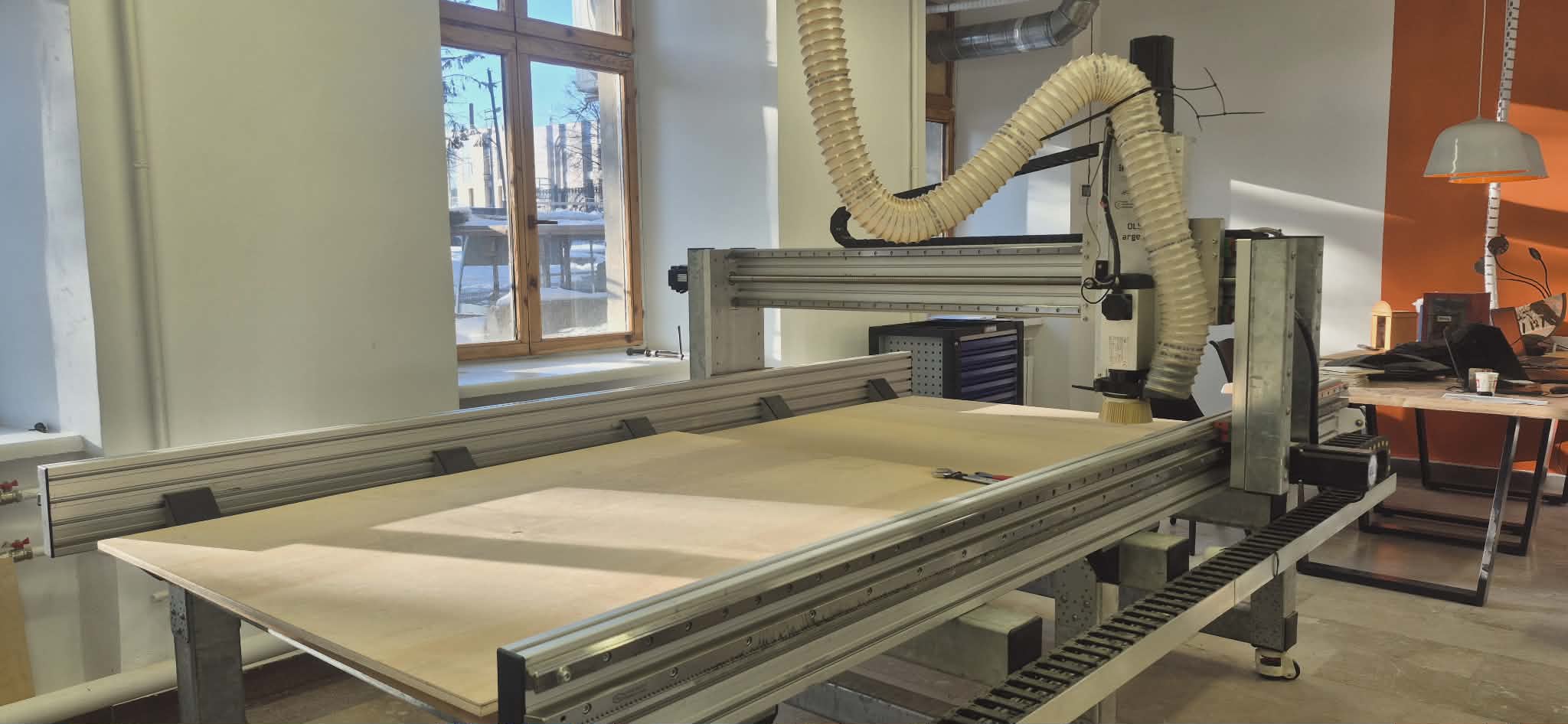
It operates along three main axes:
- X — left/right
- Y — front/back
- Z — up/down
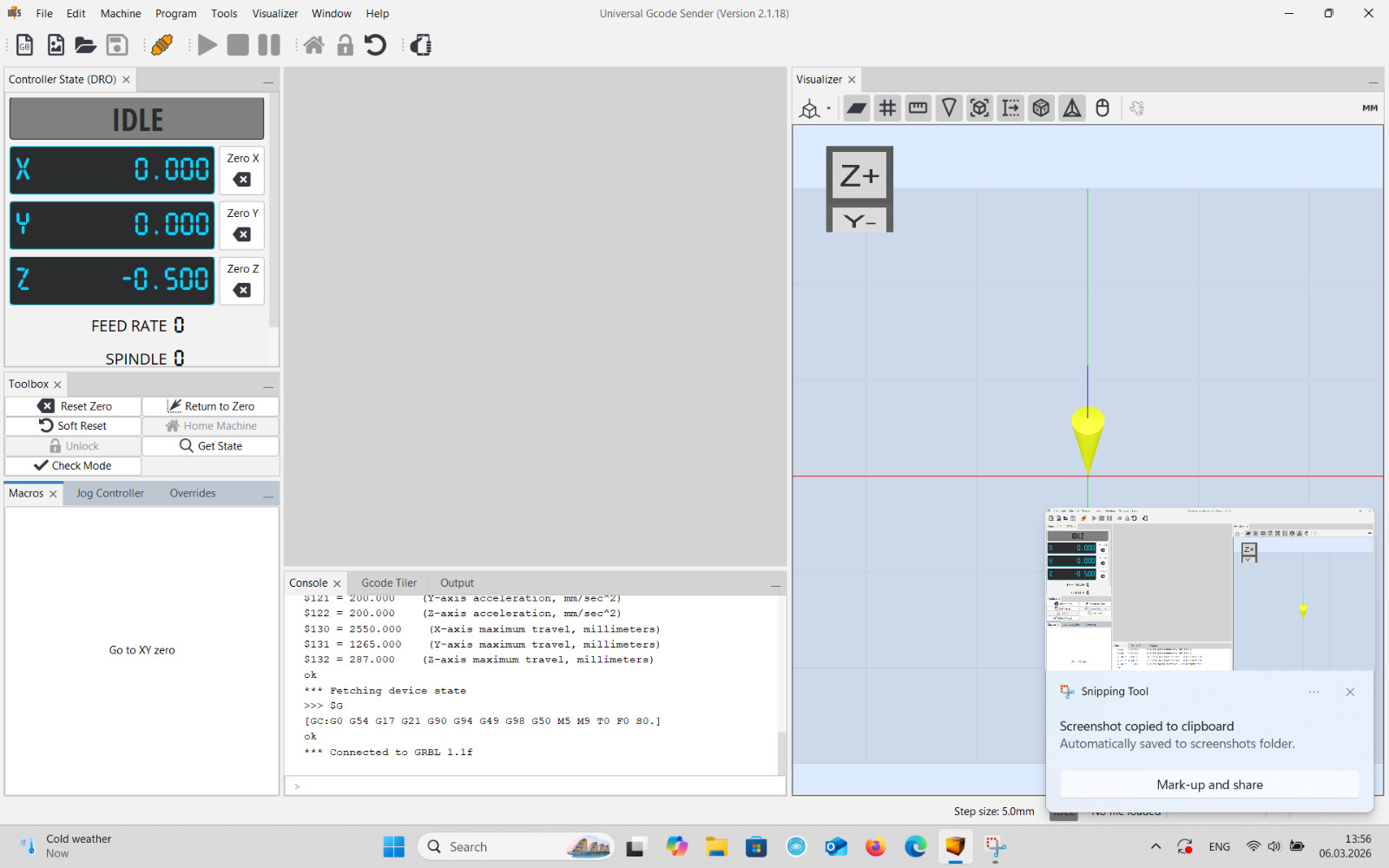
The machine is controlled via Universal G-code Sender (UGS) — open-source software that sends G-code to the machine, allows manual axis control, and monitors the job in real time.
Safety Training
Before operating the machine, we reviewed the safety rules together with the instructor.
Personal Protective Equipment (PPE):
- Safety glasses must be worn at all times
- Long hair must be tied back
- Loose clothing and jewelry must be removed
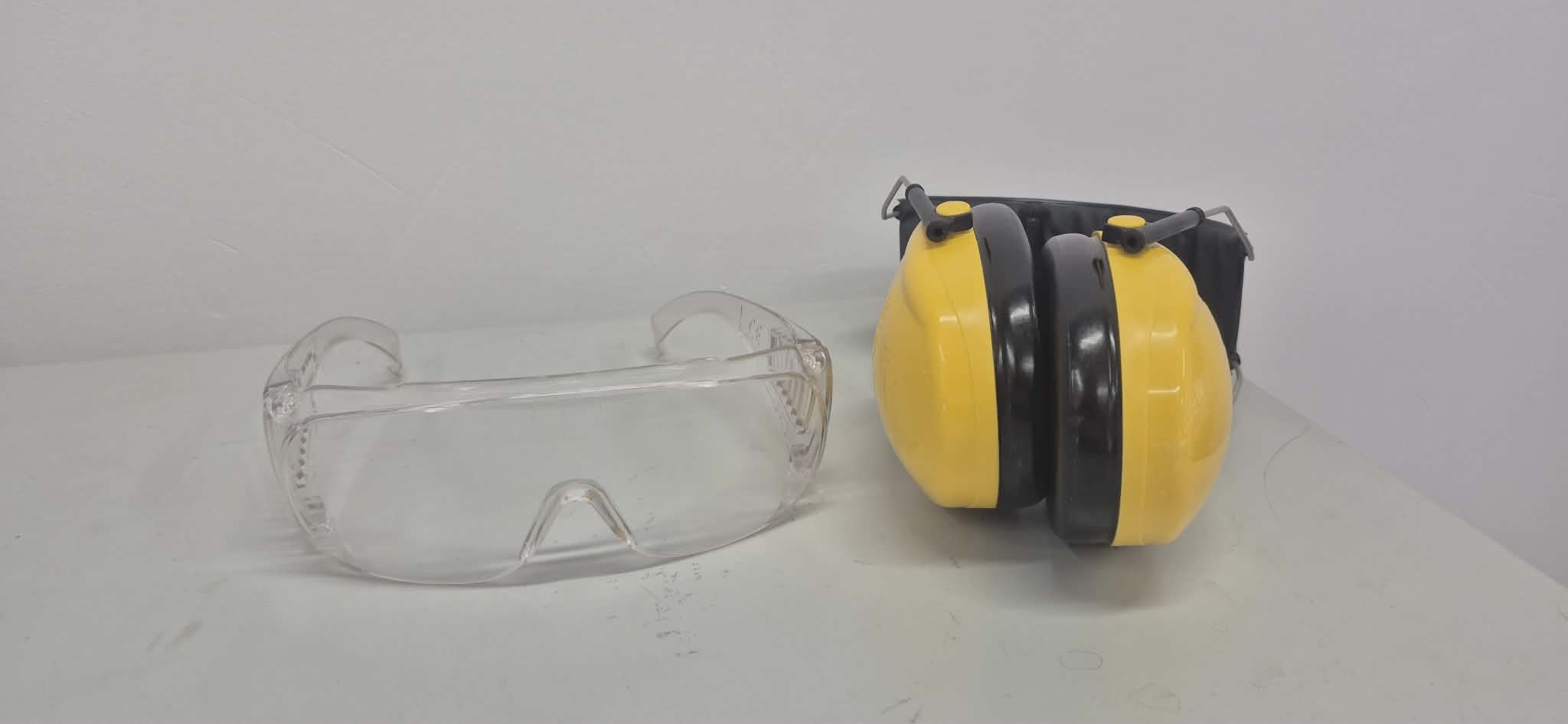
Before starting:
- The workpiece must be firmly fixed to the bed using clamps or screws
- The cutting tool must be properly installed and tightened in the collet
- Never leave the machine unattended during operation
During operation:
- Keep hands away from the cutting area
- In case of unusual sound or vibration — stop immediately using the Emergency Stop button
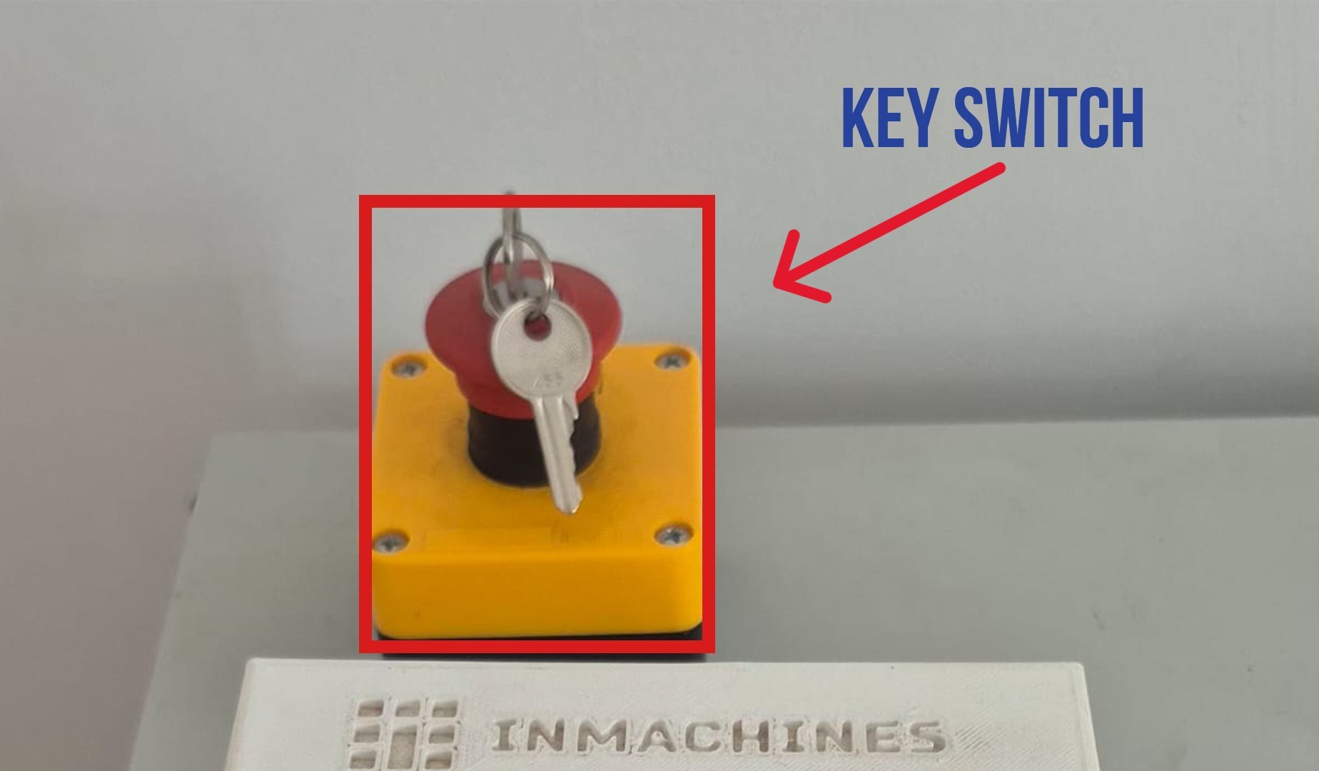
After finishing:
- Turn off the machine
- Clean chips and dust from the work area
- A fire extinguisher and fire blanket must be accessible in the workspace
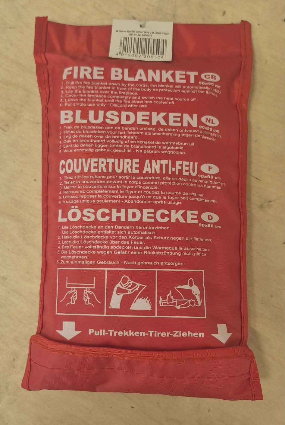
Machine Components
Power Switches
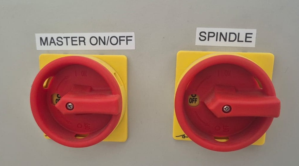
The machine has two main switches:
- MASTER ON/OFF — controls the overall power supply
- SPINDLE — turns the spindle motor on and off
Collet Set
The spindle uses ER collets to hold cutting tools. Each collet is designed for a specific tool diameter, ensuring precise and stable clamping.
Cutting Tools
We examined the following types of milling bits:
| Type | Description |
|---|---|
| Upcut | Pulls chips upward — good chip removal, but top surface may be rougher |
| Downcut | Pushes chips downward — cleaner top surface, but chips can accumulate in the cut |
| Compression | Combines upcut and downcut geometry — clean edges on both surfaces; the bit in our lab |
| Flat End Mill | General cutting, flat surfaces |
| Ball Nose | Curved surfaces and 3D machining |
| V-Bit | Engraving |
Machine Setup in UGS
If the computer does not recognize the machine after power-on:
- Go to Machine → Setup Wizard
- Click through steps, enable Enable Homing
- Enable Enable Soft Limits, then click Finish
- Press Home Machine to return to zero position
Setting Z-zero:
- Lower Z axis (step size: 1 mm)
- Switch step size to 0.1 mm for fine control
- Lower until the tool touches the material surface
- Press Zero Z
In our machine setup, the X/Y zero point (0,0) is located at the bottom-right corner of the table.
Software: Aspire 9.5
For CAM toolpath preparation we used Aspire 9.5.
Setup steps:
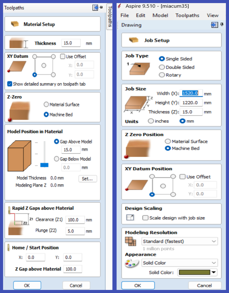
- Create a new project, set material dimensions (length, width, thickness)
- Set Z origin — on the material surface or on the machine table
- Set X/Y origin at the bottom-left corner
- Import the design file
- Open Toolpath → Material Setup and define:
- Clearance (Z1): 100 mm — safe travel height
- Z Gap Above Material: 100 mm
- Define toolpaths, select tool, set feeds and speeds
- Export G-code