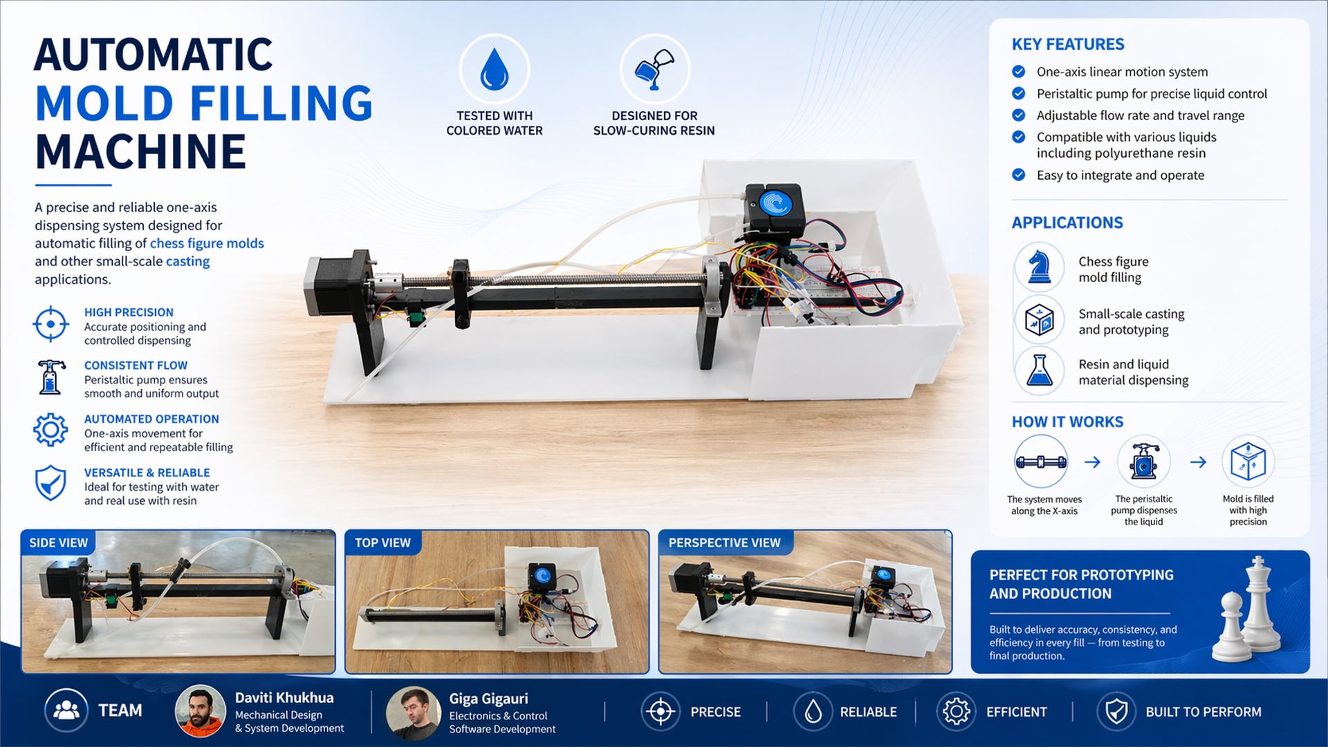
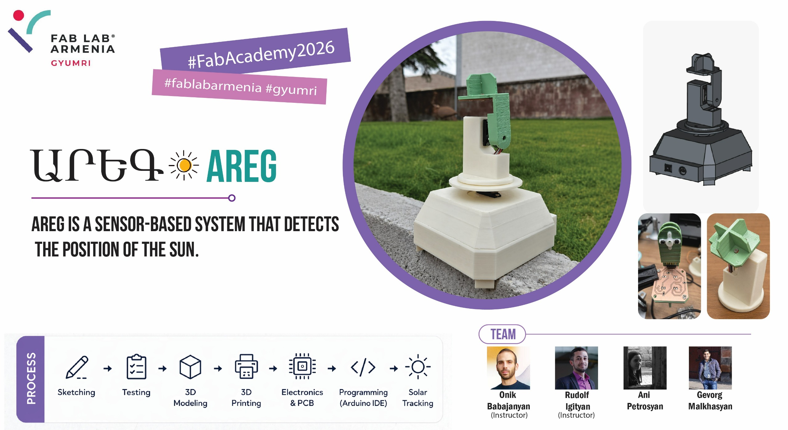
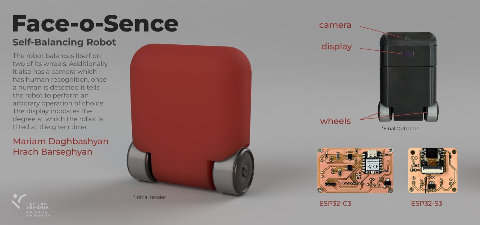
Skip to content

12 Machine building

Presentation Machine 1

slide


Presentation Machine 2

slide


Presentation Machine 3

slide


πŸ‘₯ Mariam’s Individual Contribution β€” Self-Balancing Robot

Full page: Mariam’s Week 12 documentation

πŸ€– Main Robot

This week the group assignment required us to design a machine that includes mechanism + actuation + automation + function + user interface, build the mechanical parts and operate it manually, and document both the group project and individual contributions.

After discussing many ideas, we decided to build a self-balancing robot. Mariam also proposed adding a camera that detects a smile β€” and when a smile is detected, the robot deliberately loses balance πŸ˜„. This made the individual task significantly more complex, but led to exploring several interesting technologies.

Robot sketch 1


πŸ“ Sketches of Electronics Part and Control Logic

Here are some example sketches created during research β€” this approach helps build stronger understanding, functioning as a visual database from first idea to final result.

Robot sketch 1 Robot sketch 1 Robot sketch 1 Robot sketch 1

Robot sketch 1 Robot sketch 1 Robot sketch 1 Robot sketch 1


πŸ”Œ Main Robot β€” Electronics

After finishing the research, work began on the part of the robot responsible for maintaining balance. The following components are needed for the main functionality:

1. MCU β€” Seeed Studio XIAO RP2040

Pins D0–D7 are used as follows: D0/D1 for Motor A direction, D2/D3 for Motor B direction, D4/D5 for SDA/SCL (LCD + MPU6050), D6 for LED, and D7 (RX) to receive the signal from the face detection PCB.

XIAO RP2040

2. Sensor β€” MPU6050

The MPU6050 is the "gold standard" for balancing projects β€” it combines a 3-axis accelerometer (tells the robot which way is down) and a 3-axis gyroscope (tells how fast it is falling), with 16-bit ADC for detecting very small movements.

MPU6050

3. Motors β€” 2Γ— TT DC Gear Motor (3–6V)

This is a compact and convenient option

DC Motor

4. Motor Drivers β€” 2Γ— A4953

The only motor driver available in the lab; its minimum voltage is 8V, which is not ideal for lower voltages.

A4953

5. Battery β€” 3Γ— 1200mAh 4.2V Li-Po

Compact, easy to use, and enough to power both motors and the MCU for the camera.

Battery

6. Voltage Regulator β€” LM2940

Sensitive to noise, so a 22Β΅F capacitor is used to keep the 5V rail stable.

LM2940

7. Display β€” OLED SSD1306 (IΒ²C)

Compact size and multiple colors allow nice animations.

OLED

8. Diode β€” Schottky Diode SOD123

Placed near the 5V line so that when powering from battery, USB current won't damage the MCU.

Schottky Diode

9. Resistors & Capacitors

For proper configuration and to avoid short circuits.

Resistors and Capacitors

πŸ—ΊοΈ Main Robot β€” Schematic and PCB Design

With all components and their purposes defined, the KiCad schematic and PCB designs were assembled.

Main Robot Schematic

Main Robot PCB

3D views of the PCB:

Main Robot 3D Top Main Robot 3D Back

Once the files were ready, .nc files were generated on modsproject.org for F.Cu (1/64” bit) and Edge.Cuts (1/32” bit).


πŸ”§ Main Robot β€” Soldering

All components laid out and workspace prepared:

Components needed

Workspace

Final soldered result (top and back):

Finished top Finished back


🧠 Main Robot β€” Programming & PID Control

The first test code initialized the MPU6050 and OLED and drove the motors forward β€” but without a closed-loop system the robot cannot balance. A balancing robot is like keeping a stick on your finger: without continuous correction it falls.

The robot needs PID control β€” a smarter brain that runs every few milliseconds:

Term Formula Role
🟒 P (Proportional) Kp Γ— error Reacts to current tilt
🟑 I (Integral) Ki Γ— Ξ£ error Fixes long-term drift
πŸ”΅ D (Derivative) Kd Γ— Ξ”error/Ξ”t Reacts to how fast it is falling

motor speed = P + I + D β€” recalculated every few milliseconds.

Video of the first test (MPU6050 + OLED + motors, open loop):

With Hrach’s help a temporary body was built for testing. Here are the first videos of the robot falling πŸ€ͺ:

After several tests, the SDA pin of the RP2040 burned out. The MCU was replaced with an ESP32-C3 (same pin functions), and Onik helped further stabilize the system.

MCU replacement


πŸ˜„ Smile Detection Module

Research

The XIAO ESP32-S3 Sense was chosen as a vision co-processor β€” it focuses entirely on the camera stream and smile detection, and communicates to the main MCU via a single GPIO pin (PIN 43: HIGH = smile detected, LOW = no smile).

Electronics β€” Smile Detection PCB

Components: ESP32-S3, LM2940 voltage regulator, capacitors and resistors. The PCB was also designed in KiCad.

Smile Detection Schematic

Smile Detection PCB

3D views:

Smile Detection 3D Top Smile Detection 3D Back

Soldering β€” Smile Detection

Components for smile detection PCB

Workspace 2

When attaching the ESP32-S3, double-sided tape was used under the chip to prevent its back copper layer from shorting with the PCB GND.

Milled and soldered smile detection PCB Double-sided tape trick

Final result:

Smile Detection PCB top Smile Detection PCB back

Programming β€” Smile Detection & Web Interface

The smile detection algorithm is brightness-based (grayscale, no face detector). It compares a forehead zone (top 10–25% of frame) against a mouth zone (62–85%). If the mouth is significantly brighter (teeth visible) and local contrast is high enough, a smile is counted. A web dashboard served from the ESP32-S3 shows the live brightness chart, contrast meter, total smiles, and GPIO 43 status in real time.

Web interface screenshot:

Web Interface

Smile detection demo video:

Limitation: zones are hardcoded as fixed frame percentages, so detection only works when the person is centered at a specific distance. Any position change breaks the detection β€” the algorithm doesn’t know where the face actually is.


πŸ§ͺ Person Classification β€” Edge Impulse Experiment

After the brightness-based approach proved unreliable, a custom ML model was built using Edge Impulse to classify between Mariam and Hrach.

A Python + OpenCV script auto-captured 100 face photos per person via webcam, saved into dataset/Mariam/ and dataset/Hrach/.

Running the Python script Hrach ready for capture

Mariam ready for capture HracFolder structure

The dataset was uploaded to Edge Impulse β†’ an Impulse was created (Image input β†’ Classification) β†’ features generated β†’ model trained.

Create Project in Edge Impulse Select folders

Create Impulse

Generate Features result

Save and Train result

Model testing showed 91.36% accuracy on the test set:

The model was deployed as an Arduino Library (.zip) and installed via Sketch β†’ Include Library β†’ Add .ZIP Library.

Edge Impulse built library

Install library in Arduino Library installed confirmation

Real-world result: the model recognized Hrach as Mariam, and almost any object as Hrach. The dataset of 100 images per person was far too small. πŸ˜„


πŸ‘€ Face Detection β€” Final Approach

Returning to basics: the camera only needs to detect that a person is present, not recognize who. Two built-in ESP-DL models run directly on the ESP32-S3:

  • HumanFaceDetectMSR01 β€” fast first-pass candidate detection
  • HumanFaceDetectMNP01 β€” refines candidates with a confidence threshold

Logic: Face detected β†’ PIN 43 HIGH β†’ ESP32-C3 stops balancing motors. No face for 1.5 s β†’ PIN 43 LOW β†’ robot resumes. Green bounding boxes are drawn around detected faces and the live web interface shows camera feed + detection stats.


🏁 Final Robot with Interface

After many PID coefficient adjustments and code modifications, here is the final result. The robot balances and stops when a face is detected. The balancing is not yet perfect, but the full pipeline β€” PCB design, milling, soldering, PID control, and computer vision β€” was completed in one week.


πŸ“ Files for Download

File Description
PCB Design β€” Face Detection KiCad PCB β€” ESP32-S3 face detection board
Schematic β€” Face Detection KiCad schematic β€” ESP32-S3 board
PCB Design β€” Self Balancing Robot KiCad PCB β€” ESP32-C3 main robot board
Schematic β€” Self Balancing Robot KiCad schematic β€” ESP32-C3 board

Last update: June 17, 2026