14. Interface and application programming
Group assignment:
- Compare as many tool options as possible.
- Document your work on the group work page and reflect on your individual page what you learned.
Gyumri lab
Students
What we set out to do
For the group assignment we needed to compare tools for building a user interface that communicates with a microcontroller. Rather than trying every tool we could find, we decided to focus on tools that were actually useful to us — ones we could realistically learn in a day and carry forward into the individual assignment.
We settled on three: Processing 4, Python + Tkinter, and Node-RED. Both of us tried Processing, since we planned to use it for the individual assignment as well. We also tried Tkinter and Node-RED to cover a different language and a visual, no-code approach.
To keep the comparison honest, we tested the same scenario with every tool: a button that turns the LED on our XIAO RP2040 board on and off.
Setting up the board
Before writing any UI code, we needed the board to be able to receive commands and respond to them. This raised a question: how should the computer and the board talk to each other?
We already had a USB connection and the board already used Serial.begin() in previous weeks, so Serial over USB was the natural choice. We designed a simple text protocol:
| Direction | Message | Meaning |
|---|---|---|
| PC → Board | LED_ON\n |
Turn the LED on |
| PC → Board | LED_OFF\n |
Turn the LED off |
| Board → PC | STATE:ON:255\n |
LED is on, current brightness 255 |
| Board → PC | STATE:OFF:0\n |
LED is off |
The board sends a STATE: message back after every command it receives. This way the UI always reflects the real state of the LED, not just what it last sent.
Writing the firmware
We started with just the Serial reading logic. The board reads incoming characters one by one and builds a string until it sees a newline (\n), then processes the complete command:
String inputBuffer = "";

void loop() {
  while (Serial.available()) {
    char c = (char)Serial.read();
    if (c == '\n') {
      processCommand(inputBuffer);
      inputBuffer = "";
    } else if (c != '\r') {
      inputBuffer += c;
    }
  }
}
Then we added processCommand() to act on the received string:
void processCommand(String cmd) {
  cmd.trim();
  if (cmd == "LED_ON") {
    ledState = true;
    analogWrite(LED_PIN, brightness);
  } else if (cmd == "LED_OFF") {
    ledState = false;
    analogWrite(LED_PIN, 0);
  }
  sendState();
}
We call sendState() at the end of every command so the PC always gets a confirmation.
And sendState() itself:
void sendState() {
  if (ledState)
    Serial.println("STATE:ON:" + String(brightness));
  else
    Serial.println("STATE:OFF:0");
}
The complete firmware:
const int LED_PIN = D0;

bool   ledState    = false;
int    brightness  = 255;
String inputBuffer = "";

void setup() {
  Serial.begin(9600);
  pinMode(LED_PIN, OUTPUT);
  analogWrite(LED_PIN, 0);
  delay(1000);
  sendState();
}

void loop() {
  while (Serial.available()) {
    char c = (char)Serial.read();
    if (c == '\n') {
      processCommand(inputBuffer);
      inputBuffer = "";
    } else if (c != '\r') {
      inputBuffer += c;
    }
  }
}

void processCommand(String cmd) {
  cmd.trim();
  if (cmd == "LED_ON") {
    ledState = true;
    analogWrite(LED_PIN, brightness);
  } else if (cmd == "LED_OFF") {
    ledState = false;
    analogWrite(LED_PIN, 0);
  }
  sendState();
}

void sendState() {
  if (ledState)
    Serial.println("STATE:ON:" + String(brightness));
  else
    Serial.println("STATE:OFF:0");
}
We tested it first using the Serial Monitor in Arduino IDE — typed LED_ON and pressed Enter, the LED turned on and the board replied STATE:ON:255. That confirmed the firmware was working before we touched any UI code.
(Screenshot: Serial Monitor — LED_ON command sent, STATE:ON:255 received)
Tool 1 — Processing 4 with G4P
Why Processing
We were already familiar with the Arduino IDE, so Processing felt like the natural first step. The structure is almost identical — setup() runs once, draw() runs in a loop — and the Serial library is built in. The transition required almost no adjustment.
For UI components we used the G4P library (GUI for Processing). We briefly compared it with ControlP5, the other common option, and found G4P more readable: components are created as objects with a constructor, and all button events go through a single callback function rather than through naming conventions.
How Processing and Arduino compare
It helps to see the parallels side by side:
| Arduino IDE | Processing 4 |
|---|---|
void setup() {} |
void setup() {} |
void loop() {} |
void draw() {} |
Serial.begin(9600) |
port = new Serial(this, PORT, 9600) |
Serial.println("text") |
port.write("text" + "\n") |
polling in loop() |
serialEvent() callback |
The one thing that felt different: in Processing, incoming Serial data arrives through a serialEvent() callback rather than through manual polling. Once we understood that, everything else followed naturally.
Installing G4P
- Download Processing 4 from processing.org/download
- Open Processing →
Sketch→Import Library→Manage Libraries - Search for G4P → click Install
- Restart Processing
(Screenshot: Processing Library Manager with G4P installed)
Finding the right port
Before running the sketch we needed the name of the Serial port the board was on. We found it in Arduino IDE under Tools → Port.
- Windows: something like
COM3 - Mac: something like
/dev/cu.usbmodem14101 - Linux: usually
/dev/ttyACM0
The PORT_NAME constant at the top of the sketch must match exactly — this is the most common reason a sketch fails to connect on the first try.
Writing the sketch
We started with just the Serial connection and a title, to confirm the port opened without errors:
import processing.serial.*;
import g4p_controls.*;

final String PORT_NAME = "/dev/ttyACM0";

Serial port;

void setup() {
  size(400, 280);
  port = new Serial(this, PORT_NAME, 9600);
  port.bufferUntil('\n');
}

void draw() {
  background(245);
  fill(60);
  textAlign(CENTER);
  textSize(17);
  text("XIAO RP2040 — LED Control", width / 2, 65);
}
Once that ran without errors, we added the button:
GButton btnToggle;
boolean ledOn = false;

// inside setup():
G4P.setGlobalColorScheme(GCScheme.BLUE_SCHEME);
btnToggle = new GButton(this, 140, 110, 120, 45, "Turn LED ON");
Then the callback function that G4P calls automatically when any button is clicked:
void handleButtonEvents(GButton button, GEvent event) {
  if (button == btnToggle && event == GEvent.CLICKED) {
    ledOn = !ledOn;
    port.write(ledOn ? "LED_ON\n" : "LED_OFF\n");
    btnToggle.setText(ledOn ? "Turn LED OFF" : "Turn LED ON");
  }
}
Finally, we added a label to display what the board sends back:
GLabel lblStatus;

// inside setup():
lblStatus = new GLabel(this, 80, 175, 240, 30, "Waiting for board...");
lblStatus.setTextAlign(GAlign.CENTER, GAlign.MIDDLE);
And the serialEvent() callback to update it:
void serialEvent(Serial p) {
  String msg = trim(p.readStringUntil('\n'));
  if (msg != null) {
    lblStatus.setText(msg);
    println("From board: " + msg);
  }
}
The complete sketch:
import processing.serial.*;
import g4p_controls.*;

final String PORT_NAME = "/dev/ttyACM0";

Serial  port;
GButton btnToggle;
GLabel  lblStatus;
boolean ledOn = false;

void setup() {
  size(400, 280);
  G4P.setGlobalColorScheme(GCScheme.BLUE_SCHEME);
  port = new Serial(this, PORT_NAME, 9600);
  port.bufferUntil('\n');
  btnToggle = new GButton(this, 140, 110, 120, 45, "Turn LED ON");
  lblStatus = new GLabel(this, 80, 175, 240, 30, "Waiting for board...");
  lblStatus.setTextAlign(GAlign.CENTER, GAlign.MIDDLE);
}

void draw() {
  background(245);
  fill(60);
  textAlign(CENTER);
  textSize(17);
  text("XIAO RP2040 — LED Control", width / 2, 65);
}

void handleButtonEvents(GButton button, GEvent event) {
  if (button == btnToggle && event == GEvent.CLICKED) {
    ledOn = !ledOn;
    port.write(ledOn ? "LED_ON\n" : "LED_OFF\n");
    btnToggle.setText(ledOn ? "Turn LED OFF" : "Turn LED ON");
  }
}

void serialEvent(Serial p) {
  String msg = trim(p.readStringUntil('\n'));
  if (msg != null) {
    lblStatus.setText(msg);
    println("From board: " + msg);
  }
}
A problem we ran into
When we first ran the sketch, Processing threw an error:
Error opening serial port /dev/ttyACM0: Port busy
The Serial Monitor in Arduino IDE was still open and had already claimed the port. Closing it and running the sketch again fixed the problem immediately.
Only one application can hold a Serial port at a time — something worth keeping in mind whenever a connection fails unexpectedly.
Result
(Screenshot: Processing window — button “Turn LED ON” and status label)
(Screenshot: After clicking — button text changes to “Turn LED OFF”, label shows “STATE:ON:255”, LED on board is on)
What we noticed
setup()anddraw()required no adjustment — they work exactly like in Arduino- Building incrementally (connect first, button second, label third) helped us catch the port-busy error early instead of debugging a full sketch
handleButtonEvents()handles all buttons in one place — you checkif (button == btnToggle)to know which one was clickedserialEvent()fires automatically, so we never had to think about when to read the port
Tool 2 — Python + Tkinter
Why Tkinter
We wanted to try a completely different language to see how the Serial logic changes — or doesn’t — when you leave the Processing world. Tkinter is Python’s built-in GUI library, so there is nothing to install beyond pyserial. It seemed like the fairest, most minimal comparison.
Installation
pip install pyserial
That is the only step. Tkinter ships with Python.
Writing the code
We started with just the window and the Serial connection, no button yet:
import tkinter as tk
import serial

PORT      = "/dev/ttyACM0"
BAUD_RATE = 9600

ser = serial.Serial(PORT, BAUD_RATE, timeout=1)

root = tk.Tk()
root.title("LED Control — Tkinter")
root.geometry("300x200")

tk.Label(root, text="XIAO RP2040", font=("Arial", 16, "bold")).pack(pady=20)

root.mainloop()
Then we added the toggle button and its function:
led_on = False

def toggle_led():
    global led_on
    led_on = not led_on
    ser.write(("LED_ON\n" if led_on else "LED_OFF\n").encode("utf-8"))
    btn.config(
        text = "Turn LED OFF" if led_on else "Turn LED ON",
        bg   = "#48c78e"     if led_on else "#cccccc"
    )

btn = tk.Button(root, text="Turn LED ON", font=("Arial", 13),
                bg="#cccccc", command=toggle_led, padx=20, pady=10)
btn.pack()
At this point the button worked — it sent commands to the board — but the status label never updated. The reason was that ser.readline() blocks: it waits until a line arrives, and while it waits the entire window freezes. We needed to run the Serial reading somewhere else.
The solution is a background thread:
import threading

def read_loop():
    while True:
        line = ser.readline().decode("utf-8").strip()
        if line:
            lbl_status.config(text=line)

threading.Thread(target=read_loop, daemon=True).start()
daemon=True ensures the thread stops automatically when the window is closed.
The complete code:
import tkinter as tk
import serial
import threading

PORT      = "/dev/ttyACM0"
BAUD_RATE = 9600

ser    = serial.Serial(PORT, BAUD_RATE, timeout=1)
led_on = False

def toggle_led():
    global led_on
    led_on = not led_on
    ser.write(("LED_ON\n" if led_on else "LED_OFF\n").encode("utf-8"))
    btn.config(
        text = "Turn LED OFF" if led_on else "Turn LED ON",
        bg   = "#48c78e"     if led_on else "#cccccc"
    )

def read_loop():
    while True:
        line = ser.readline().decode("utf-8").strip()
        if line:
            lbl_status.config(text=line)

root = tk.Tk()
root.title("LED Control — Tkinter")
root.geometry("300x200")

tk.Label(root, text="XIAO RP2040", font=("Arial", 16, "bold")).pack(pady=20)

btn = tk.Button(root, text="Turn LED ON", font=("Arial", 13),
                bg="#cccccc", command=toggle_led, padx=20, pady=10)
btn.pack()

lbl_status = tk.Label(root, text="Waiting...", fg="gray", font=("Arial", 11))
lbl_status.pack(pady=10)

threading.Thread(target=read_loop, daemon=True).start()
root.mainloop()
Result
(Screenshot: Tkinter window — button “Turn LED ON”)
(Screenshot: After clicking — button turns green, label shows “STATE:ON:255”)
What we noticed
- The Serial logic is essentially the same as in Processing: open port → write string → read string. The language changed, the pattern did not
- The threading requirement was the one genuinely new concept — something you never encounter in Arduino because there is only ever one thing happening at a time
- The UI looks plain compared to Processing, but the code took less time to write
Tool 3 — Node-RED
Why Node-RED
We wanted to include a tool where the approach is fundamentally different — no code at all, just connecting blocks visually. Node-RED has a built-in Serial node and is widely used in IoT projects, so it seemed like the most representative option for that category.
Installation
npm install -g node-red
npm install -g node-red-dashboard
npm install -g node-red-node-serialport
Start it:
node-red
Then open http://localhost:1880 in a browser. To load our flow: Menu (☰) → Import → paste the contents of fabacademy_led_flow.json → Deploy. The dashboard is at http://localhost:1880/ui.
How the flow works
Instead of writing code, we connected nodes:
| Node | Type | What it does |
|---|---|---|
| Button ON | ui_button |
Sends the string LED_ON to the next node |
| Button OFF | ui_button |
Sends the string LED_OFF |
| → XIAO RP2040 | serial out |
Writes the string to the Serial port |
| ← XIAO RP2040 | serial in |
Reads lines coming from the board |
| Parse STATE | function |
Parses STATE:ON:200 into readable text |
| Status | ui_text |
Displays the result on the dashboard |
(Screenshot: Node-RED editor — all nodes connected)
The only code we wrote
One small JavaScript function inside the function node, to parse the board’s response:
var line = msg.payload.toString().trim();

if (line.startsWith("STATE:")) {
    var parts = line.split(":");
    var ledOn  = parts[1] === "ON";
    var bright = parseInt(parts[2]);

    msg.payload = ledOn
        ? "LED on — brightness " + bright
        : "LED off";
}

return msg;
Result
(Screenshot: Node-RED Dashboard at localhost:1880/ui — two buttons and status text)
What we noticed
- The flow was working in about 15 minutes — faster than either of the other two tools
- Configuring the Serial node took three clicks: choose the port, set 9600 baud, set
\nas the delimiter - The dashboard opens in any browser, including on a phone on the same network
- For any logic beyond button presses you still end up writing JavaScript in
functionnodes — code is unavoidable - The most significant downside for learning: it is easy to get something working without understanding what is actually happening at the Serial level. Everything is hidden inside the nodes
Comparing the three tools
| Processing + G4P | Python + Tkinter | Node-RED | |
|---|---|---|---|
| Language | Java-like | Python | Visual + JS |
| Install | Processing IDE + G4P | pip install pyserial |
npm + 2 modules |
| Serial | Built-in Serial class |
pyserial |
Serial node |
| Feels like Arduino | Yes — identical structure | Partially — same logic, different syntax | No |
| Time to working result | ~30 min | ~25 min | ~15 min |
| Teaches Serial internals | ✅ | ✅ | ⚠️ hidden inside nodes |
The three tools represent genuinely different approaches: writing a program you understand line by line (Processing, Python) versus assembling a working system from pre-built parts (Node-RED). For the individual assignment we chose Processing — because we want to understand what the code is doing, and the parallel with Arduino made that much easier.
Possible improvements
-
Our comparison covered only the simplest scenario — one button, one LED. A more complete test would add a slider for PWM brightness control and see how each tool handles continuous input alongside discrete commands.
-
The Node-RED dashboard works from any browser on the local network, which means a mobile interface with no extra effort. None of the other tools offer that out of the box, and it could be worth exploring in a future project.
-
In the Tkinter version, calling
lbl_status.config()from the background thread is not technically safe — Tkinter expects all UI updates to happen on the main thread. It works in practice but the correct approach would be to useroot.after()to schedule updates from the main thread instead.
Files
xiao_rp2040_firmware.ino— board firmwareLED_Control_G4P/LED_Control_G4P.pde— Processing + G4P sketchled_control_tkinter.py— Python + Tkinterfabacademy_led_flow.json— Node-RED flow
Dilijan Lab
Web Interface for Color Sensor
We first built an interface for the TCS3472 Color Sensor.
We decided to display the detected color from the sensor directly on a web page using a WiFi IP address.
Since we wanted to create a web interface, besides the sensor we needed an MCU with WiFi capability, so we chose the ESP32-C3, which we have used many times, together with the TCS3472 Color Sensor.
After briefly studying how to use the TCS3472, we moved to the connections. We only needed these connections:
- TCS3472 VCC → ESP32C3 3V3
- TCS3472 GND → ESP32C3 GND
- TCS3472 SDA → ESP32C3 GPIO8 (default I2C SDA)
- TCS3472 SCL → ESP32C3 GPIO9 (default I2C SCL)
Since we didn’t have a free ESP32C3 at that moment, we used our RC PCB, and since we couldn’t connect directly to the correct pins, we connected wires from the back and fixed them with tape so they would stay stable.
Now everything was ready for programming.
Here is the full code. In the AI era, it is easy to generate code.
Prompt:
“ESP32-C3 colour sensor web interface using the TCS34725 sensor. The system reads RGB colour values, detects the nearest colour name, hosts a live Wi-Fi webpage showing a glowing colour preview with RGB values and HEX code, and continuously sends RGB data to Unity through Serial communication for real-time game interaction.”
Code running on the ESP32-C3:
/*
  ESP32-C3 + TCS34725 Colour Sensor — Wi-Fi Web Interface
  =========================================================
  Wiring:
    TCS34725 VCC  → ESP32-C3 3V3
    TCS34725 GND  → ESP32-C3 GND
    TCS34725 SDA  → ESP32-C3 GPIO8  (default I2C SDA)
    TCS34725 SCL  → ESP32-C3 GPIO9  (default I2C SCL)

  Libraries needed (install via Arduino Library Manager):
    - "Adafruit TCS34725"  by Adafruit
    - "Adafruit BusIO"     by Adafruit  (dependency)
    - WiFi (built-in with ESP32 core)

  Usage:
    1. Fill in Wi-Fi SSID and PASSWORD below.
    2. Flash the sketch.
    3. Open Serial Monitor at 115200 to see the assigned IP.
    4. Open that IP in a browser on the same network.
*/

#include <WiFi.h>
#include <WebServer.h>
#include <Wire.h>
#include "Adafruit_TCS34725.h"

struct RGB { uint8_t r, g, b; uint16_t c; bool ok; };

// ── Wi-Fi credentials ──────────────────────────────────────────────
const char* WIFI_SSID     = "staff";
const char* WIFI_PASSWORD = "SRGB2020";
// ──────────────────────────────────────────────────────────────────

// TCS34725: 50 ms integration, gain ×4  (tweak if sensor is in bright/dark env)
Adafruit_TCS34725 tcs = Adafruit_TCS34725(TCS34725_INTEGRATIONTIME_50MS,
                                           TCS34725_GAIN_4X);

WebServer server(80);

// ── Colour name lookup (simple nearest-colour in RGB space) ────────
struct NamedColour { const char* name; uint8_t r, g, b; };

const NamedColour PALETTE[] = {
  {"Red",        220,  20,  60},
  {"Orange",     255, 140,   0},
  {"Yellow",     255, 215,   0},
  {"Yellow-Green",154, 205,  50},
  {"Green",       34, 139,  34},
  {"Cyan",         0, 206, 209},
  {"Blue",        30, 144, 255},
  {"Indigo",      75,   0, 130},
  {"Violet",     148,   0, 211},
  {"Pink",       255, 105, 180},
  {"White",      255, 255, 255},
  {"Light Grey", 180, 180, 180},
  {"Grey",       128, 128, 128},
  {"Dark Grey",   64,  64,  64},
  {"Black",        0,   0,   0},
  {"Brown",       139,  69,  19},
  {"Beige",       245, 245, 220},
};

String nearestColourName(uint8_t r, uint8_t g, uint8_t b) {
  long best = LONG_MAX;
  const char* name = "Unknown";
  for (auto& c : PALETTE) {
    long dr = (long)r - c.r, dg = (long)g - c.g, db = (long)b - c.b;
    long dist = dr*dr + dg*dg + db*db;
    if (dist < best) { best = dist; name = c.name; }
  }
  return String(name);
}

// ── Read sensor → normalised 0-255 RGB ────────────────────────────
//struct RGB { uint8_t r, g, b; uint16_t c; bool ok; };

RGB readSensor() {
  uint16_t raw_r, raw_g, raw_b, raw_c;
  tcs.getRawData(&raw_r, &raw_g, &raw_b, &raw_c);

  if (raw_c == 0) return {0, 0, 0, 0, false};

  // Normalise against clear channel so brightness cancels out
  uint8_t r = constrain((uint32_t)raw_r * 255 / raw_c, 0, 255);
  uint8_t g = constrain((uint32_t)raw_g * 255 / raw_c, 0, 255);
  uint8_t b = constrain((uint32_t)raw_b * 255 / raw_c, 0, 255);
  return {r, g, b, raw_c, true};
}

// ── HTML page ─────────────────────────────────────────────────────
const char HTML_HEAD[] PROGMEM = R"rawliteral(
<!DOCTYPE html>
<html lang="en">
<head>
<meta charset="UTF-8">
<meta name="viewport" content="width=device-width,initial-scale=1">
<title>Colour Sensor</title>
<style>
  @import url('https://fonts.googleapis.com/css2?family=Space+Mono:wght@400;700&family=DM+Sans:wght@300;500&display=swap');
  :root{--bg:#0e0e12;--panel:#17171f;--border:#2a2a38;--accent:#7c6cfa;--text:#e8e8f0;--sub:#888}
  *{box-sizing:border-box;margin:0;padding:0}
  body{background:var(--bg);color:var(--text);font-family:'DM Sans',sans-serif;
       min-height:100vh;display:flex;flex-direction:column;align-items:center;
       justify-content:flex-start;padding:40px 20px}
  h1{font-family:'Space Mono',monospace;font-size:1.1rem;letter-spacing:.2em;
     text-transform:uppercase;color:var(--sub);margin-bottom:40px}
  #swatch{width:220px;height:220px;border-radius:50%;border:3px solid var(--border);
          box-shadow:0 0 60px rgba(124,108,250,.15);transition:background .4s,box-shadow .4s;
          margin-bottom:32px;background:#222}
  #name{font-family:'Space Mono',monospace;font-size:1.5rem;font-weight:700;
        letter-spacing:.05em;margin-bottom:8px;transition:color .4s}
  #hex{font-family:'Space Mono',monospace;font-size:.9rem;color:var(--sub);margin-bottom:32px}
  .stats{display:grid;grid-template-columns:repeat(3,1fr);gap:12px;width:100%;max-width:360px;margin-bottom:32px}
  .stat{background:var(--panel);border:1px solid var(--border);border-radius:12px;
        padding:16px;text-align:center}
  .stat-label{font-size:.65rem;letter-spacing:.15em;text-transform:uppercase;color:var(--sub);margin-bottom:6px}
  .stat-value{font-family:'Space Mono',monospace;font-size:1.3rem;font-weight:700}
  #status{font-size:.75rem;color:var(--sub);letter-spacing:.1em}
  .dot{display:inline-block;width:7px;height:7px;border-radius:50%;
       background:var(--accent);margin-right:6px;animation:pulse 1.4s infinite}
  @keyframes pulse{0%,100%{opacity:1}50%{opacity:.3}}
</style>
</head>
<body>
<h1>⬡ Colour Sensor · TCS34725</h1>
<div id="swatch"></div>
<div id="name">—</div>
<div id="hex">#------</div>
<div class="stats">
  <div class="stat"><div class="stat-label">Red</div><div class="stat-value" id="rv">—</div></div>
  <div class="stat"><div class="stat-label">Green</div><div class="stat-value" id="gv">—</div></div>
  <div class="stat"><div class="stat-label">Blue</div><div class="stat-value" id="bv">—</div></div>
</div>
<div id="status"><span class="dot"></span>Live · updates every 1 s</div>
<script>
function toHex(n){return n.toString(16).padStart(2,'0').toUpperCase()}
function luma(r,g,b){return 0.299*r+0.587*g+0.114*b}
async function poll(){
  try{
    const res=await fetch('/data');
    const d=await res.json();
    const hex='#'+toHex(d.r)+toHex(d.g)+toHex(d.b);
    document.getElementById('swatch').style.background=hex;
    document.getElementById('swatch').style.boxShadow=`0 0 80px ${hex}55`;
    document.getElementById('name').textContent=d.name;
    document.getElementById('name').style.color=hex;
    document.getElementById('hex').textContent=hex;
    document.getElementById('rv').textContent=d.r;
    document.getElementById('gv').textContent=d.g;
    document.getElementById('bv').textContent=d.b;
  }catch(e){document.getElementById('status').textContent='⚠ connection lost'}
}
poll();setInterval(poll,1000);
</script>
</body></html>
)rawliteral";

// ── Route handlers ─────────────────────────────────────────────────
void handleRoot() {
  server.send_P(200, "text/html", HTML_HEAD);
}

void handleData() {
  RGB px = readSensor();
  if (!px.ok) {
    server.send(500, "application/json", "{\"error\":\"sensor read failed\"}");
    return;
  }
  String name = nearestColourName(px.r, px.g, px.b);
  char buf[128];
  snprintf(buf, sizeof(buf),
    "{\"r\":%d,\"g\":%d,\"b\":%d,\"clear\":%d,\"name\":\"%s\"}",
    px.r, px.g, px.b, px.c, name.c_str());
  server.send(200, "application/json", buf);
}

// ── Setup ──────────────────────────────────────────────────────────
void setup() {
  Serial.begin(115200);
  delay(500);

  // I2C on default ESP32-C3 pins (SDA=8, SCL=9) — change if needed
  Wire.begin(6, 7);

  if (!tcs.begin()) {
    Serial.println("[ERROR] TCS34725 not found! Check wiring.");
    while (1) delay(1000);
  }
  Serial.println("[OK] TCS34725 initialised");

  // Connect to Wi-Fi
  Serial.printf("[WiFi] Connecting to %s", WIFI_SSID);
  WiFi.begin(WIFI_SSID, WIFI_PASSWORD);
  while (WiFi.status() != WL_CONNECTED) {
    delay(500);
    Serial.print(".");
  }
  Serial.printf("\n[WiFi] Connected! IP: http://%s\n", WiFi.localIP().toString().c_str());

  server.on("/",      handleRoot);
  server.on("/data",  handleData);
  server.begin();
  Serial.println("[HTTP] Server started");
}

// ── Loop ───────────────────────────────────────────────────────────
void loop() {
  server.handleClient(); // Keep your web interface running

  RGB px = readSensor();
  if (px.ok) {
    // Send "R,G,B" to Unity via Serial
    Serial.print(px.r); Serial.print(",");
    Serial.print(px.g); Serial.print(",");
    Serial.println(px.b);
  }
  delay(50); // Send data frequently for smooth updates
}
How it works
The ESP32 connects to a WiFi network using the provided SSID and password. Once connected, it starts a web server on port 80 and prints its local IP address to the Arduino Serial Monitor.
Any device connected to the same WiFi network can then open this IP address in a web browser. When the browser connects, the ESP32 sends the HTML, CSS, and JavaScript code stored in the program as plain text.
The browser then interprets and executes this code locally on the connected device, generating the user interface. The JavaScript continuously requests updated sensor data from the ESP32, allowing the webpage to display live colour information in real time.
And this is the final result:
Colour Sensor Interface in Unity Game
Then we created a game scene interface that reflects in real time the colour detected by the colour sensor. The Directional Light also changes dynamically depending on the detected colour.
Arduino Code
To achieve this, together with Claude, we developed a system that creates a real-time communication interface between the ESP32-C3 + TCS34725 colour sensor and the Unity game engine using Serial communication.
AI Prompt:
“ESP32-C3 + TCS34725 colour sensor interface for Unity game. Reads RGB colour values from the TCS34725 sensor using I2C communication, converts raw data into normalized RGB values, detects the nearest predefined colour name, and sends real-time JSON data through Serial communication to Unity every 100ms. Unity can use this data to control gameplay elements such as lights, puzzles, materials, doors, or interactions based on detected real-world colours.”
The system continuously reads colours from the TCS34725 colour sensor through I2C communication. The raw sensor values are then converted into normalized RGB values to make them easier to use inside Unity.
Additionally, the program compares the measured RGB values with a predefined colour palette and determines the closest human-readable colour name.
Finally, the ESP32 sends the colour data to Unity in JSON format through Serial communication, allowing Unity to update objects, materials, and lighting in real time based on the detected physical colour.
#include <Wire.h>
#include "Adafruit_TCS34725.h"

// ════════════════════════════════════════════════════════════════════
//  SENSOR READ
// ════════════════════════════════════════════════════════════════════
struct ColourReading { uint8_t r, g, b; uint16_t clear; bool ok; };

#define SERIAL_INTERVAL_MS 100   // how often to send data to Unity

// TCS34725: 50ms integration, gain x4
// Adjust gain if colours look wrong:
//   Very bright environment  → TCS34725_GAIN_1X
//   Normal                   → TCS34725_GAIN_4X
//   Dim environment          → TCS34725_GAIN_16X
Adafruit_TCS34725 tcs = Adafruit_TCS34725(
  TCS34725_INTEGRATIONTIME_50MS,
  TCS34725_GAIN_4X
);


// ════════════════════════════════════════════════════════════════════
//  COLOUR NAME LOOKUP
// ════════════════════════════════════════════════════════════════════
struct NamedColour { const char* name; uint8_t r, g, b; };

const NamedColour PALETTE[] = {
  {"Red",          220,  20,  60},
  {"Orange",       255, 140,   0},
  {"Yellow",       255, 215,   0},
  {"Yellow-Green", 154, 205,  50},
  {"Green",         34, 139,  34},
  {"Cyan",           0, 206, 209},
  {"Blue",          30, 144, 255},
  {"Indigo",        75,   0, 130},
  {"Violet",       148,   0, 211},
  {"Pink",         255, 105, 180},
  {"White",        255, 255, 255},
  {"Light Grey",   180, 180, 180},
  {"Grey",         128, 128, 128},
  {"Dark Grey",     64,  64,  64},
  {"Black",          0,   0,   0},
  {"Brown",        139,  69,  19},
  {"Beige",        245, 245, 220},
};

String nearestColourName(uint8_t r, uint8_t g, uint8_t b) {
  long best = LONG_MAX;
  const char* name = "Unknown";
  for (auto& c : PALETTE) {
    long dr = (long)r - c.r;
    long dg = (long)g - c.g;
    long db = (long)b - c.b;
    long dist = dr*dr + dg*dg + db*db;
    if (dist < best) { best = dist; name = c.name; }
  }
  return String(name);
}


ColourReading readSensor() {
  uint16_t raw_r, raw_g, raw_b, raw_c;
  tcs.getRawData(&raw_r, &raw_g, &raw_b, &raw_c);
  if (raw_c == 0) return {0, 0, 0, 0, false};
  uint8_t r = (uint8_t)constrain((uint32_t)raw_r * 255 / raw_c, 0, 255);
  uint8_t g = (uint8_t)constrain((uint32_t)raw_g * 255 / raw_c, 0, 255);
  uint8_t b = (uint8_t)constrain((uint32_t)raw_b * 255 / raw_c, 0, 255);
  return {r, g, b, raw_c, true};
}


// ════════════════════════════════════════════════════════════════════
//  SETUP
// ════════════════════════════════════════════════════════════════════
void setup() {
  Serial.begin(115200);
  delay(500);
  Serial.println("[BOOT] TCS34725 Colour Sensor starting...");

  Wire.begin(6, 7);  // SDA=GPIO6, SCL=GPIO7

  if (!tcs.begin()) {
    Serial.println("[ERROR] TCS34725 not found! Check SDA/SCL wiring.");
    while (1) {
      delay(1000);
      Serial.println("[ERROR] Halted — sensor not detected.");
    }
  }

  tcs.setInterrupt(false);  // turn on the sensor LED
  Serial.println("[OK] TCS34725 ready — sending JSON to Unity...");
}


// ════════════════════════════════════════════════════════════════════
//  LOOP
// ════════════════════════════════════════════════════════════════════
void loop() {
  static unsigned long lastSend = 0;

  if (millis() - lastSend >= SERIAL_INTERVAL_MS) {
    lastSend = millis();

    ColourReading px = readSensor();
    if (px.ok) {
      String name = nearestColourName(px.r, px.g, px.b);
      // Newline-terminated JSON — Unity reads line by line
      Serial.printf(
        "{\"r\":%d,\"g\":%d,\"b\":%d,\"name\":\"%s\"}\n",
        px.r, px.g, px.b, name.c_str()
      );
    }
  }
}
Unity Game Engine
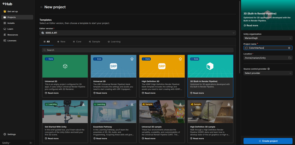
After downloading Unity from the Official site, we open New Project and choose 3D Built-in Render Pipeline.
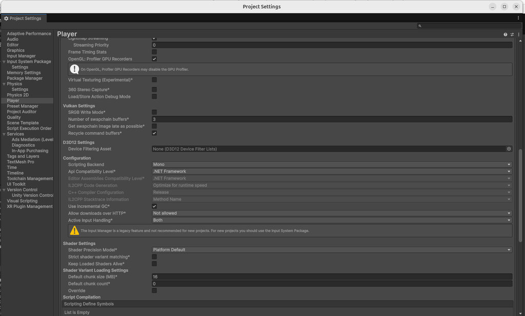
Before starting, go to Edit → Project Settings → Player → Other Settings, and from Api Compatibility Level select .NET Framework (instead of .NET Standard), so the project has access to a larger set of libraries. This is important because we will use external plugins (SDKs). Also, in Active Input Handling, select Both, to avoid errors when one part of the project uses the old system and another uses the new one.
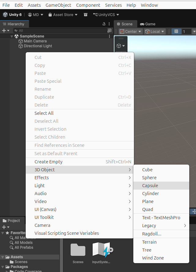
Since we want to use the color sensor to build a game interface, we will create a small scene with:
- a main player as a Capsule
- some objects like Cube and Sphere
To do this, right-click in Hierarchy -> 3D Object and select the needed objects.
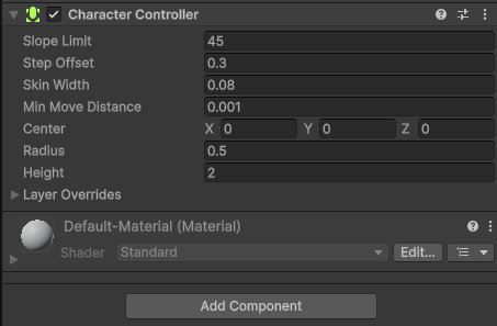
Now we programmed these objects.
From the Inspector, we clicked Add Component and add Character Controller.
Then, in the Assets section, we created a new folder called Scripts to store all code files.

Prompt:
“Please write a Unity C# script that creates a first-person player controller using the CharacterController component. It should handle player movement, jumping, gravity, and mouse-based camera rotation. The player should be able to move with WASD, jump using the Space key, and rotate the camera only while holding the right mouse button. The cursor should become hidden and locked during camera rotation and visible again when released.”
using UnityEngine;

public class PlayerController : MonoBehaviour {
    public CharacterController controller;
    public Transform cameraTransform;

    [Header("Movement Settings")]
    public float speed = 6f;
    public float gravity = -9.81f;
    public float jumpHeight = 2f;

    [Header("Look Settings")]
    public float lookSpeed = 2f;
    public float lookXLimit = 85f;

    private Vector3 velocity;
    private float rotationX = 0;

    void Start() {
        controller = GetComponent();

        // We don't lock the cursor at start anymore so you can use the right-click freely
        Cursor.lockState = CursorLockMode.None;
        Cursor.visible = true;
    }

    void Update() {
        // --- 1. MOVEMENT ---
        float x = Input.GetAxis("Horizontal");
        float z = Input.GetAxis("Vertical");

        Vector3 move = transform.right * x + transform.forward * z;
        controller.Move(move * speed * Time.deltaTime);

        // --- 2. JUMPING ---
        if (Input.GetButtonDown("Jump") && controller.isGrounded) {
            // Formula for jump velocity: sqrt(height * -2 * gravity)
            velocity.y = Mathf.Sqrt(jumpHeight * -2f * gravity);
        }

        // --- 3. ROTATION (Only when Right Mouse Button is held) ---
        if (Input.GetMouseButton(1)) {
            // Hide cursor while rotating
            Cursor.visible = false;
            Cursor.lockState = CursorLockMode.Locked;

            // Rotate player body (Left/Right)
            transform.Rotate(0, Input.GetAxis("Mouse X") * lookSpeed, 0);

            // Rotate camera (Up/Down)
            rotationX += -Input.GetAxis("Mouse Y") * lookSpeed;
            rotationX = Mathf.Clamp(rotationX, -lookXLimit, lookXLimit);
            cameraTransform.localRotation = Quaternion.Euler(rotationX, 0, 0);
        } else {
            // Show cursor when button is released
            Cursor.visible = true;
            Cursor.lockState = CursorLockMode.None;
        }

        // --- 4. GRAVITY ---
        if (controller.isGrounded && velocity.y < 0) {
            velocity.y = -2f;
        }
        velocity.y += gravity * Time.deltaTime;
        controller.Move(velocity * Time.deltaTime);
    }
}
Then, in the Hierarchy we created an empty GameObject by selecting Right Click -> Create Empty. We named it ColourReader, and attached the SerialColourReader script to it, which we will show below.
Then, inside the Inspector, we assigned all the public parameters of the script.
This image shows the setup in detail.

Here is the ColourReader code, which I again generated together with Claude.
Prompt:
“Unity C# script reads real-time colour data from an ESP32-C3 through Serial communication and applies the detected colour to scene objects and directional light. It uses a background thread to safely read JSON colour packets, parses RGB values, smoothly interpolates colours using Lerp, and updates materials and lighting in the Unity scene for interactive colour-based gameplay.”
using System;
using System.Collections.Concurrent;
using System.IO.Ports;
using System.Threading;
using UnityEngine;

public class SerialColourReader : MonoBehaviour
{
    [Header("Serial")]
    [SerializeField] string portName = "/dev/ttyACM0";   // change to your port
    [SerializeField] int baudRate   = 115200;

    [Header("Scene objects")]
    [SerializeField] Renderer[] colourTargets;   // drag 2 cubes + 2 spheres here
    [SerializeField] Light directionalLight;

    [Header("Smoothing")]
    [SerializeField] float lerpSpeed = 8f;       // 0 = instant, higher = smoother

    // ── internals ──────────────────────────────────────────
    SerialPort _port;
    Thread     _readThread;
    volatile bool _running;
    readonly ConcurrentQueue _queue = new();

    Color _targetColor  = Color.white;
    Color _currentColor = Color.white;

    // ── lifecycle ──────────────────────────────────────────
    void Start()
    {
        _port = new SerialPort(portName, baudRate) { ReadTimeout = 500 };
        try
        {
            _port.Open();
            _running = true;
            _readThread = new Thread(ReadLoop) { IsBackground = true };
            _readThread.Start();
            Debug.Log("[ColourReader] Serial port opened.");
        }
        catch (Exception e) { Debug.LogError($"[ColourReader] {e.Message}"); }
    }

    void OnDestroy()
    {
        _running = false;
        _readThread?.Join(1000);
        if (_port?.IsOpen == true) _port.Close();
    }

    // ── background thread: just enqueue raw lines ──────────
    void ReadLoop()
    {
        while (_running)
        {
            try
            {
                string line = _port.ReadLine();         // blocks up to ReadTimeout
                if (!string.IsNullOrWhiteSpace(line))
                    _queue.Enqueue(line);
            }
            catch (TimeoutException) { /* normal, keep looping */ }
            catch (Exception e)
            {
                Debug.LogWarning($"[ColourReader] {e.Message}");
                _running = false;
            }
        }
    }

    // ── main thread: parse + apply ─────────────────────────
    void Update()
    {
        // drain queue (at most a few lines per frame)
        while (_queue.TryDequeue(out string line))
            TryParseColor(line);

        // smooth lerp toward target
        _currentColor = Color.Lerp(_currentColor, _targetColor, Time.deltaTime * lerpSpeed);
        ApplyColor(_currentColor);
    }

    void TryParseColor(string json)
    {
        // Arduino sends: {"r":220,"g":20,"b":60,"name":"Red"}
        try
        {
            var data = JsonUtility.FromJson(json);
            _targetColor = new Color(data.r / 255f, data.g / 255f, data.b / 255f);
        }
        catch { /* malformed packet — ignore */ }
    }

    void ApplyColor(Color c)
    {
        foreach (var r in colourTargets)
            if (r != null) r.material.color = c;

        if (directionalLight != null)
            directionalLight.color = c;
    }

    // ── JSON helper ────────────────────────────────────────
    [Serializable]
    class ColourPacket { public int r, g, b; public string name; }
}
And this is the result: