8. Electronics Production
This week we had to:
-
characterize the design rules for our in-house PCB production process
-
submit a PCB design to a board house
Dilijan and Gyumri Laboratories
Both our laboratories use the Roland SRM-20 CNC machine for PCB fabrication.
Electronic Components
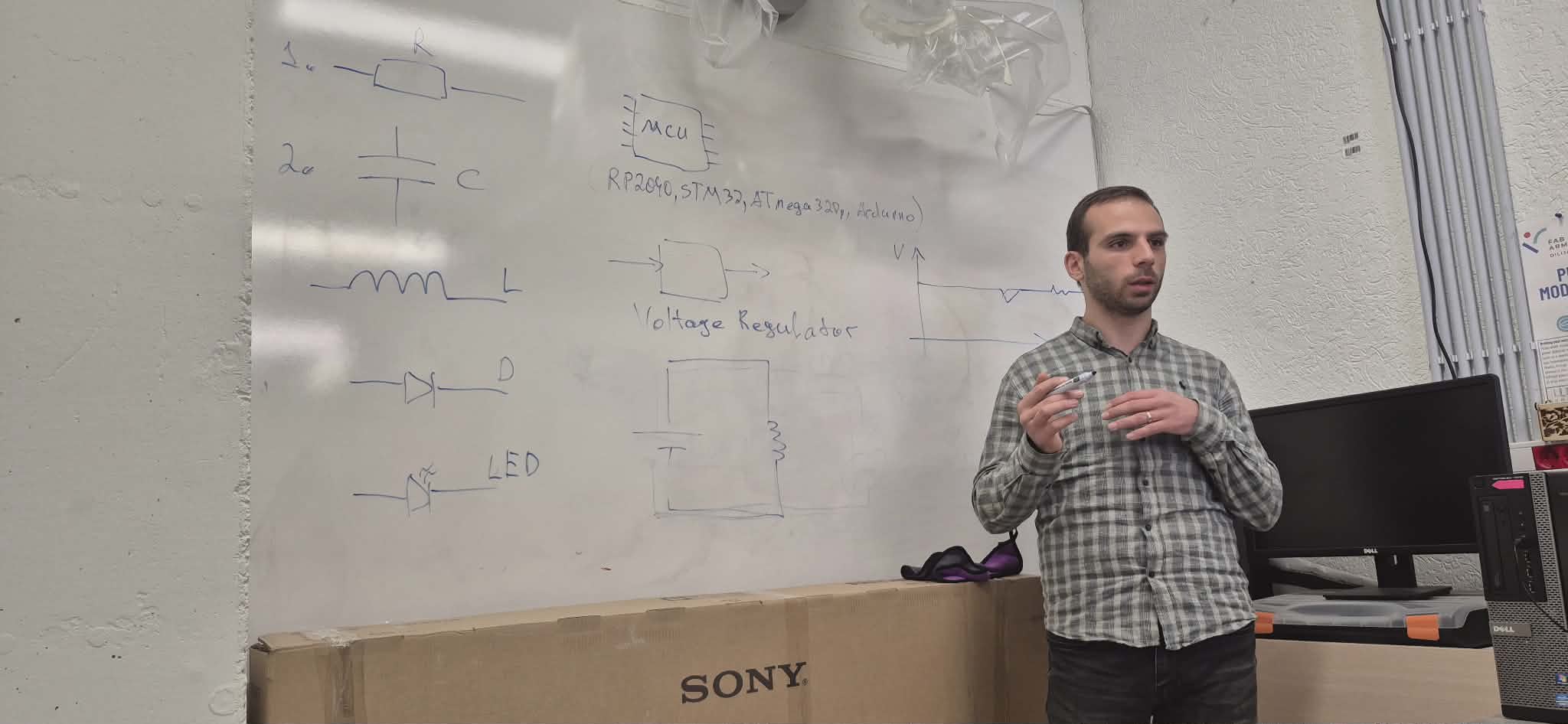
This week our instructor Onik Babajanyan introduced us to the basic electronic components and explained their role in electronic circuits: resistors, capacitors, LEDs, diodes, MOSFET transistors, voltage regulators, and transistors.
Preparation
After finishing the file generation, we had to complete some preparation steps before starting the actual PCB milling process.
Securing the Board to the Bed
The SRM-20 bed surface is made of MDF. To secure the copper board to it, we use double-sided tape:
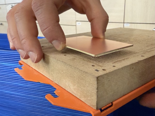
Since the copper sheet may have some warping, and the milling depth for traces is only 0.1mm, any unevenness can cause inaccuracies — either insufficient cutting or cutting too deep. The tape presses the board firmly against the surface and prevents this.
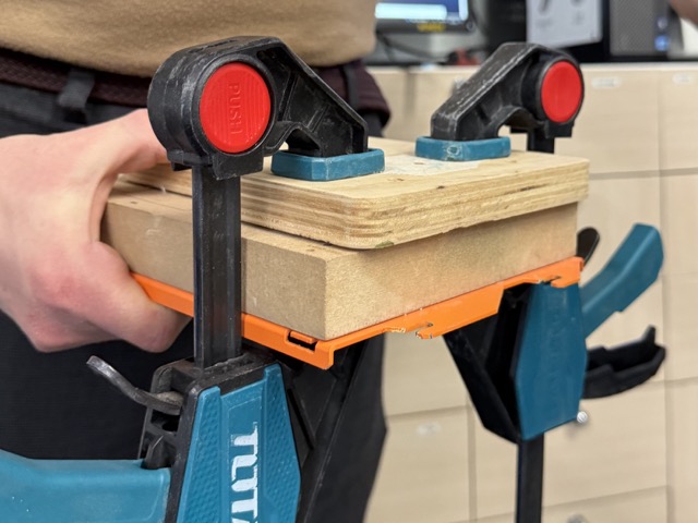
To ensure even stronger adhesion, we also placed an 18mm plywood sheet on top of the board, clamped it with two clamps, and left it for 10–15 minutes.
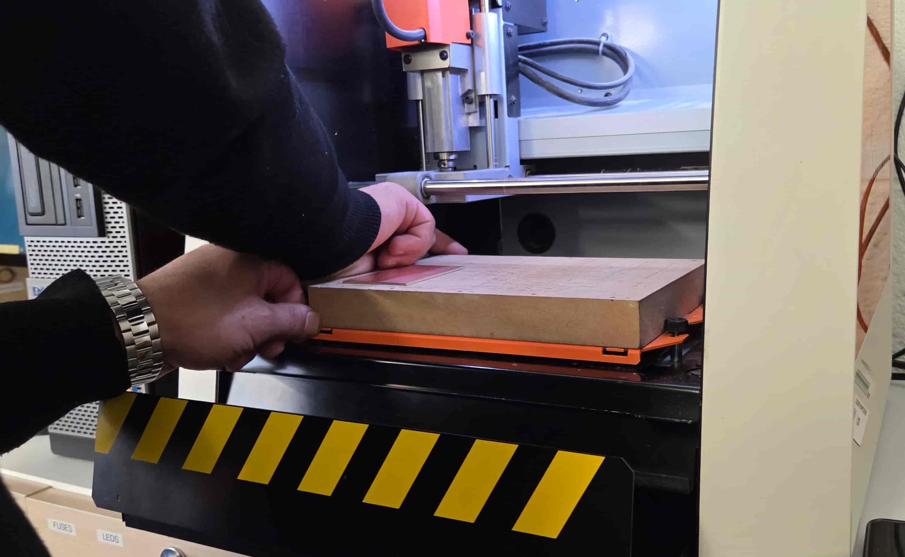
Once the PCB sheet is securely attached to the MDF surface, the removable table is placed in place and secured with screws:
Control Software
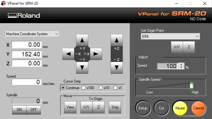
We use VPanel for SRM-20 to operate the CNC milling machine:
Machine Calibration
Since the copper board is replaced almost every session, and a new board is not always positioned in the same spot, XY zero coordinates need to be recalibrated each time.
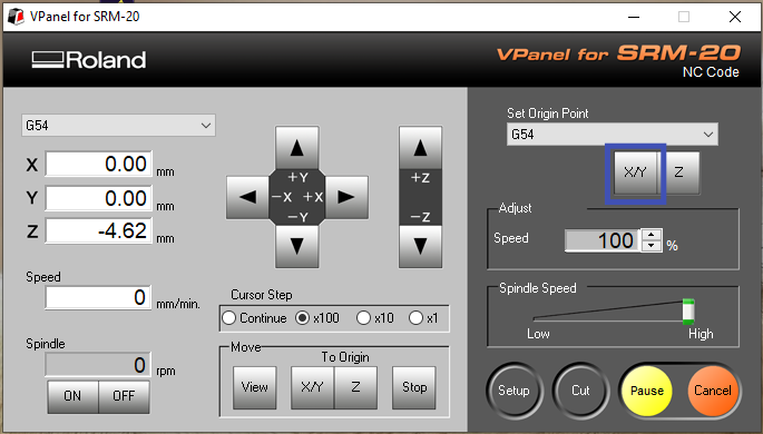
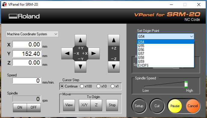
To calibrate XY, we use the movement controls to move the bit to the desired position — typically the bottom-left corner — and press the X/Y button. That point becomes the (0, 0) origin.
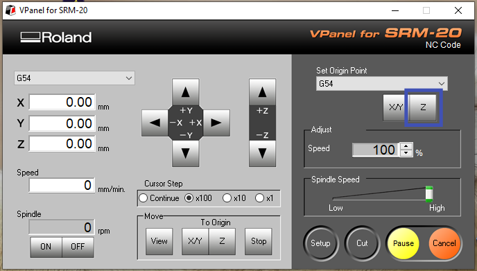
When changing the bit, the Z position may also shift and require recalibration. To zero the Z axis, we manually lower the bit close to the board. Once it is close enough, we use the appropriate hex key to release the bit and carefully lower it until it touches the surface. Once contact is made, we tighten the screw and press the Z button to zero the Z axis.
It is also worth noting that when using .nc files, multiple coordinate systems are available, controlled by codes G54 through G59. When files are generated with modsproject, the default coordinate system is G54.
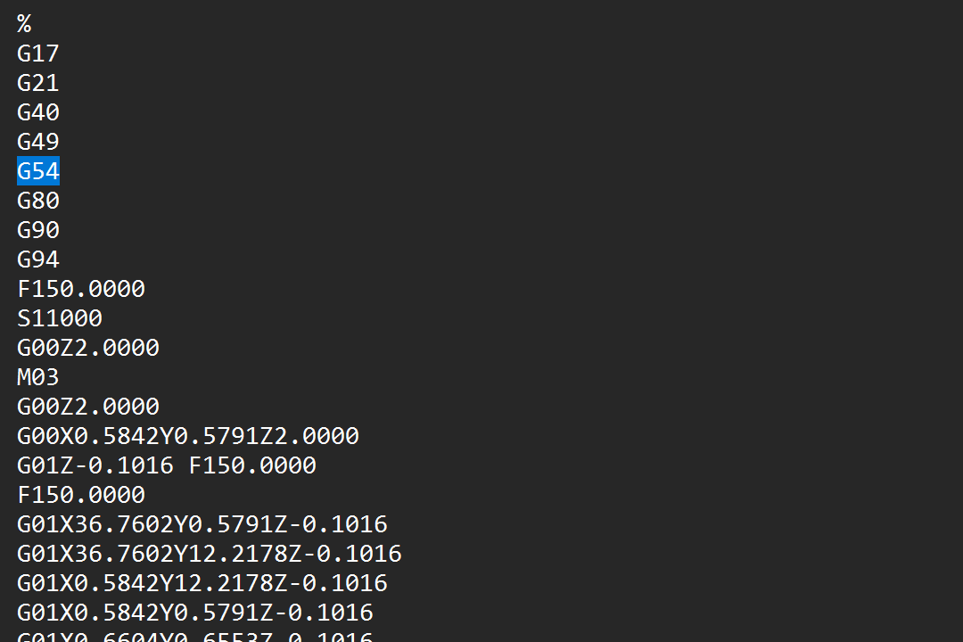
When zeroing coordinates, make sure to select the correct coordinate system accordingly.
G-code Generation
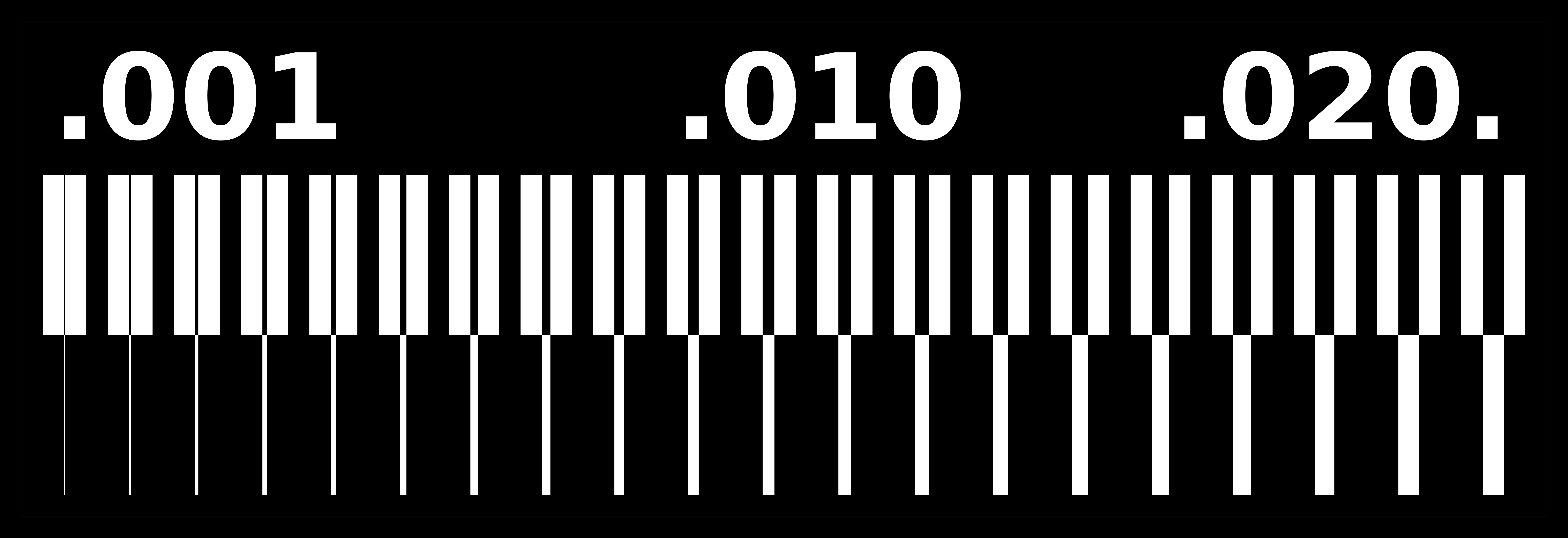
As a test, we used the ready-made line test traces design from Fab Academy.
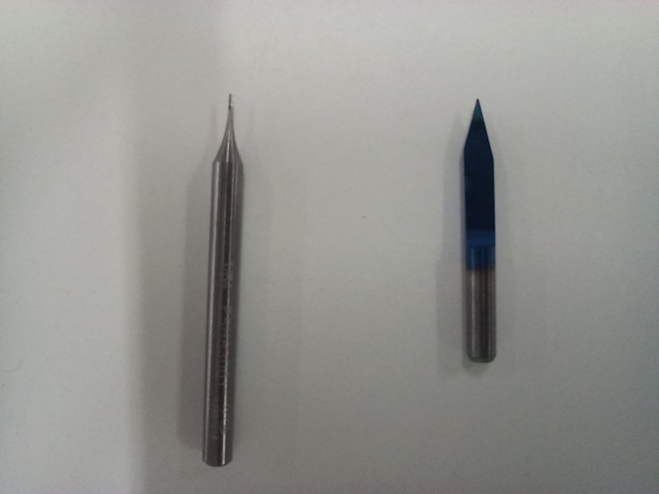
We tested two types of bits — a 1/64 Flat end mill and an inch V-bit — to see which one performs better.
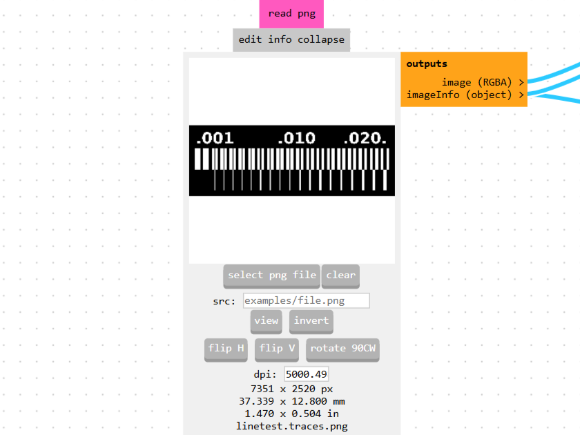
For G-code generation we used Fab Mods. It supports multiple file formats. Go to Programs, then select mill 2D PCB from the list.
The program accepts two file types: SVG and PNG. In our case it’s PNG, so we click select png file.
G-code for the Flat End Mill
After loading the file, we select the operation type and tool. We choose Traces as the operation and 1/64 flat as the tool.
Default settings are applied automatically: tool diameter, cut depth, max depth, offset number, and offset stepover.
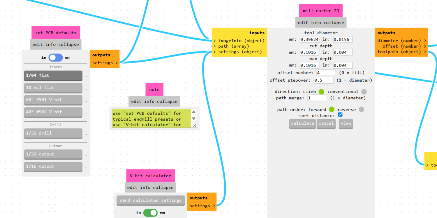
The only parameter we changed was tool diameter — set to 0.4mm for the Gyumri lab, as their bits are metric. Max depth stays at 0.1mm, which is sufficient since the copper layer is only 0.07mm thick. Cut depth is also left unchanged at 25% of the bit diameter, which is a safe value.
Speed and spindle RPM settings were applied in a separate panel:
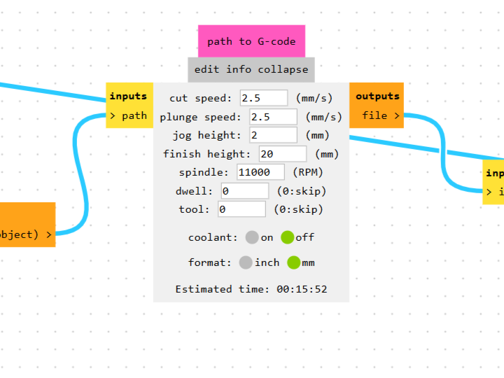
As we later discovered, the actual spindle speed of our machine does not reach the specified value and runs at around 9000 RPM.
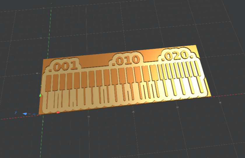
After reviewing the settings, click calculate. A 3D visualization window opens automatically:
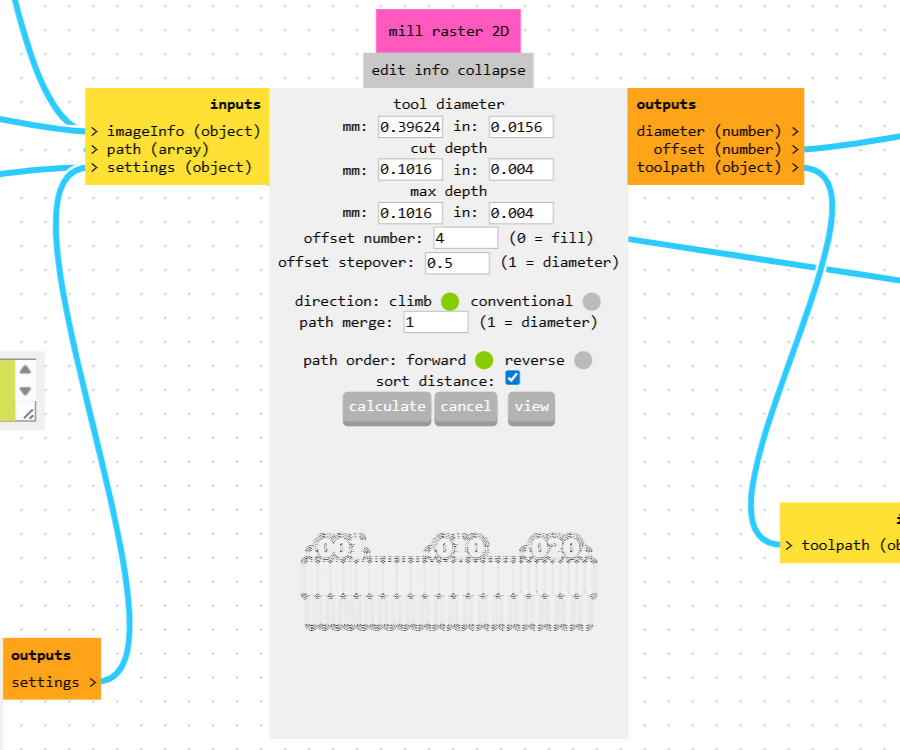
A path preview also appears at the bottom of the panel:
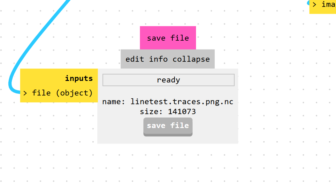
To save the file, go to the corresponding panel and click save file:
G-code for the V-bit
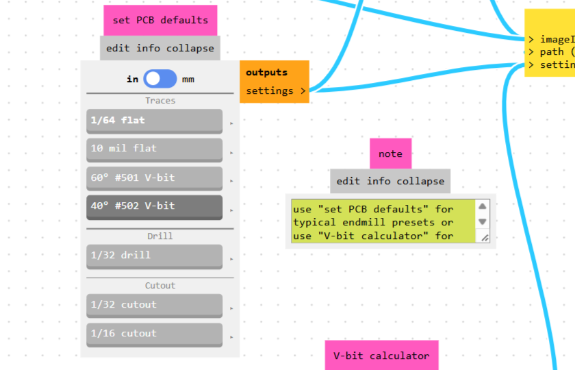
The process for the V-bit is almost identical to the flat end mill, except for the tool selection. The standard panel offers two V-bit options: 60° and 40°. However, the V-bit available in our lab has a 30° angle. For this case, there is a V-bit calculator.
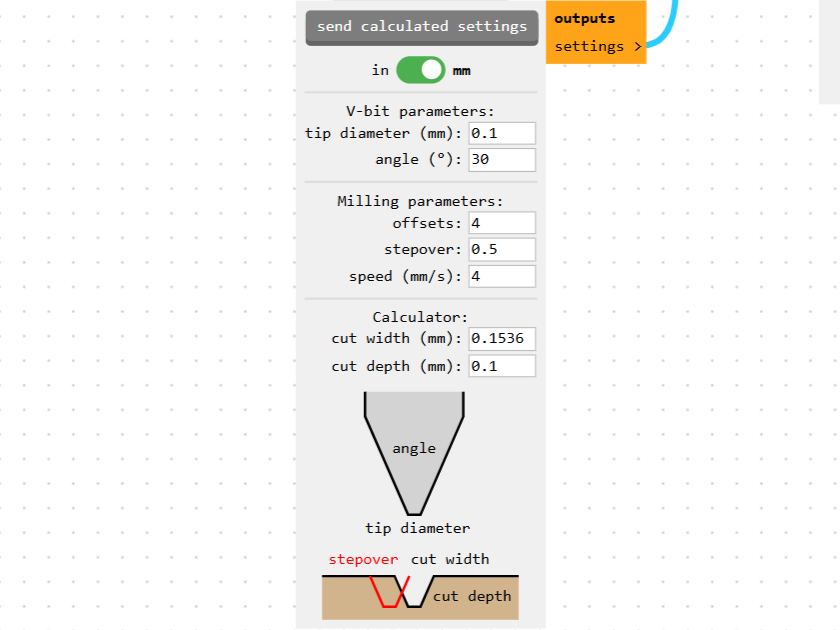
Here we set the tip diameter — in our case 0.1mm — and the angle, which is 30°. It is also important to specify the cut depth; as mentioned earlier, we set it to 0.1mm, and the calculator automatically computes the cut width. To apply the result, click send calculated settings.
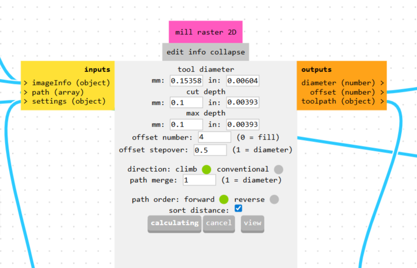
The values are then passed to the next panel for G-code generation, and the process repeats:
Milling Process
Once the preparation and G-code generation were complete, we proceeded to the actual milling.
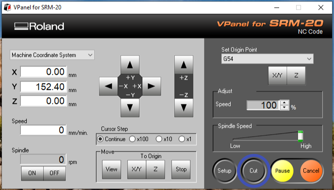
Open VPanel for SRM-20 and click Cut:
A dialog window will open. The program remembers the last loaded file, so first click Delete All, then click Add to open a file browser and load the new file from the computer.
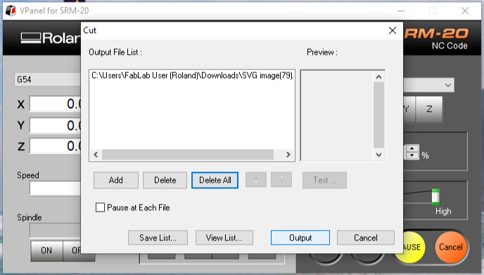
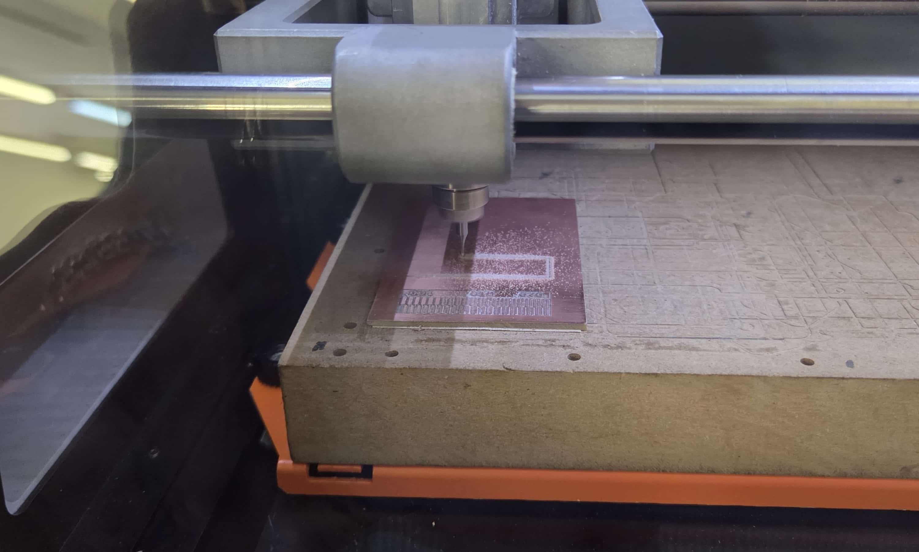
Once the file is loaded, click Output and the machine will start:
Results
The top pattern was milled with the 1/64 flat end mill, the bottom one with the V-bit.
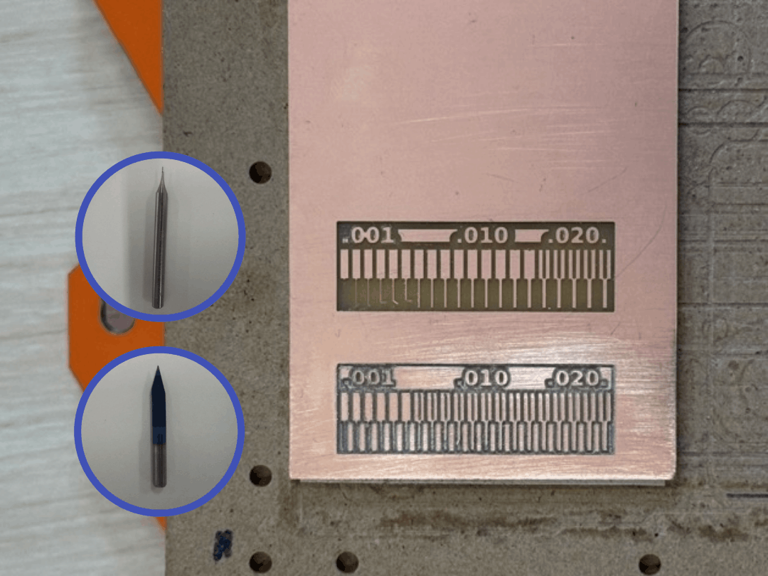
The test evaluates each bit’s ability to clear tight gaps, maintain trace integrity at different widths, and produce clean edges. The numbers on the board indicate trace/gap widths in inches.
The flat end mill produced clean, well-defined traces across all widths. Even the narrowest gaps at .001” are clearly separated.
The V-bit results are less consistent. Since the offset number was set to 4 in both cases, and the V-bit tip diameter is very small, it does not cover the adjacent copper area between passes — leaving some zones incompletely cleared. It is also worth noting that after milling, we sanded only the V-bit section of the board, which affected the surface appearance in that area.
For reliable PCB fabrication, the 1/64 flat end mill is the preferred choice.
Sending a PCB to a Board House
As part of this week’s group assignment, we documented the process of sending a PCB design to an external board house, in order to compare it with our in-house milling workflow. We used PCBasic for this.
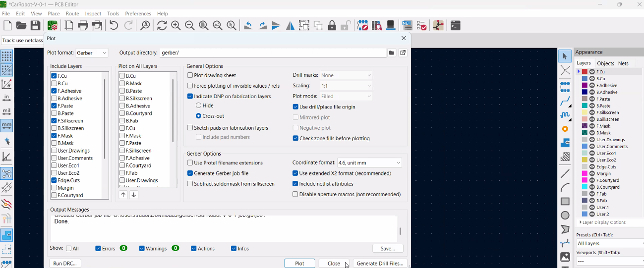
Before uploading anything, we exported the Gerber files from KiCad’s PCB Editor, making sure the correct layers were checked and the plot settings matched what a manufacturer expects.
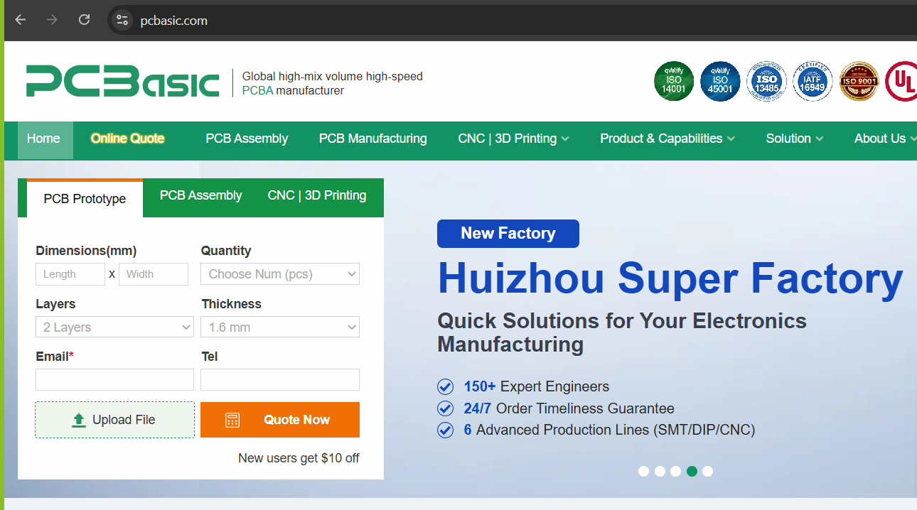
We then went to the PCBasic website and opened their Online Quote tool for PCB prototypes.
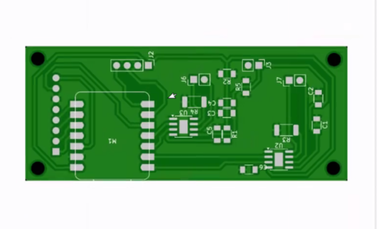
After entering the board’s dimensions, the site generated a preview of our board from the uploaded files, so we could check that it had read the design correctly before going further.
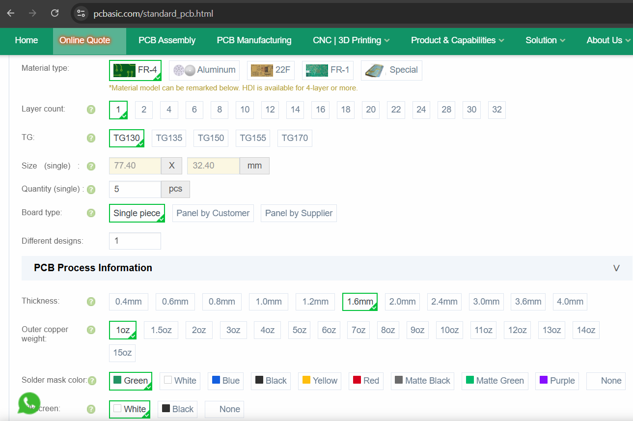
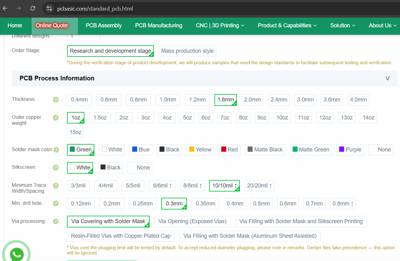
From there, we went through the manufacturing options one by one:
- Material type: FR-4 (the standard PCB substrate)
- Layer count: 1 (our board is single-sided)
- Board type: Single piece
- Thickness: 1.6 mm
- Outer copper weight: 1 oz
- Solder mask color: Green
- Silkscreen: White
Further down, we set the production tolerances to match what our design actually needs:
- Minimum trace width/spacing: 10/10 mil
- Minimum drill hole: 0.3 mm
- Via processing: Via covering with solder mask
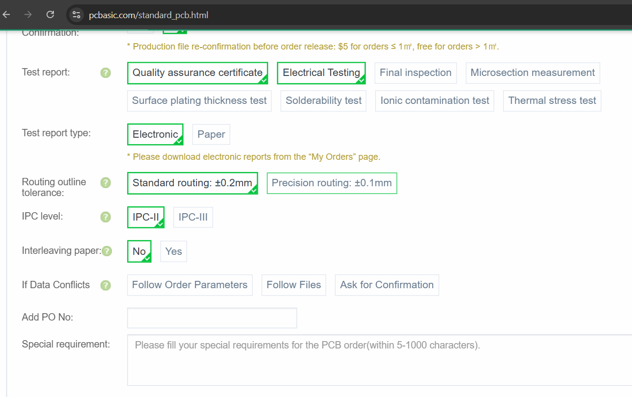
We also selected the quality and testing options for the order:
- Test report: Quality assurance certificate + Electrical testing
- Test report type: Electronic
- Routing outline tolerance: Standard routing (±0.2 mm)
- IPC level: IPC-II
With all the parameters set, we added the order to the cart. The site automatically reviewed the files and gave us a price of $11 for 10 pieces (32.4 × 77.4 mm, FR-4, 1.6 mm), with an estimated 3-day build time, and the order reached the Awaiting Payment stage.
Since it was our first order on the platform, we also got a $10 discount as a new-user bonus. The cart showed an estimated shipping cost of $35, and the total package weight was 0.08 kg.
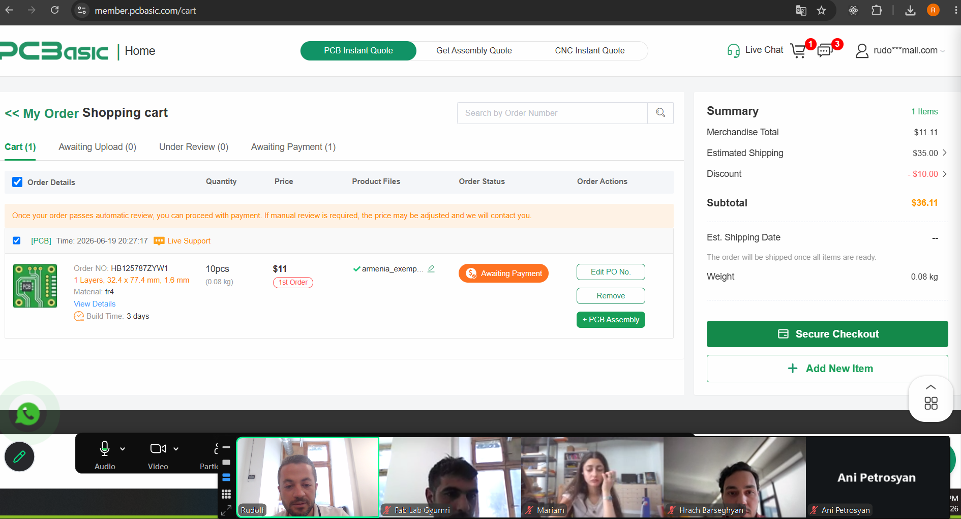
We stopped here without completing the purchase — the assignment only requires documenting the workflow up to the final payment step, not actually placing the order.