3. Computer controlled cutting
Group assignment:
- Do your lab’s safety training
- Characterize your lasercutter’s focus, power, speed, rate, kerf, joint clearance and types.
- Document your work to the group work page and reflect on your individual page what you learned.
This week, we worked with two machines: a vinyl cutter and a laser cutter.
Dilijan Lab
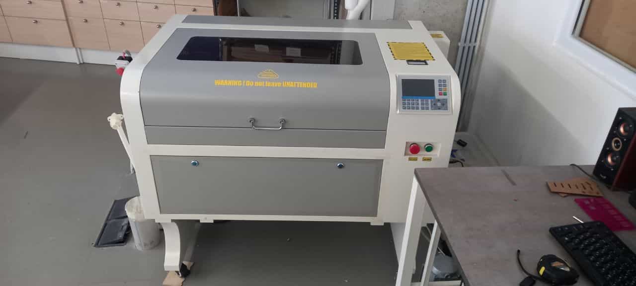
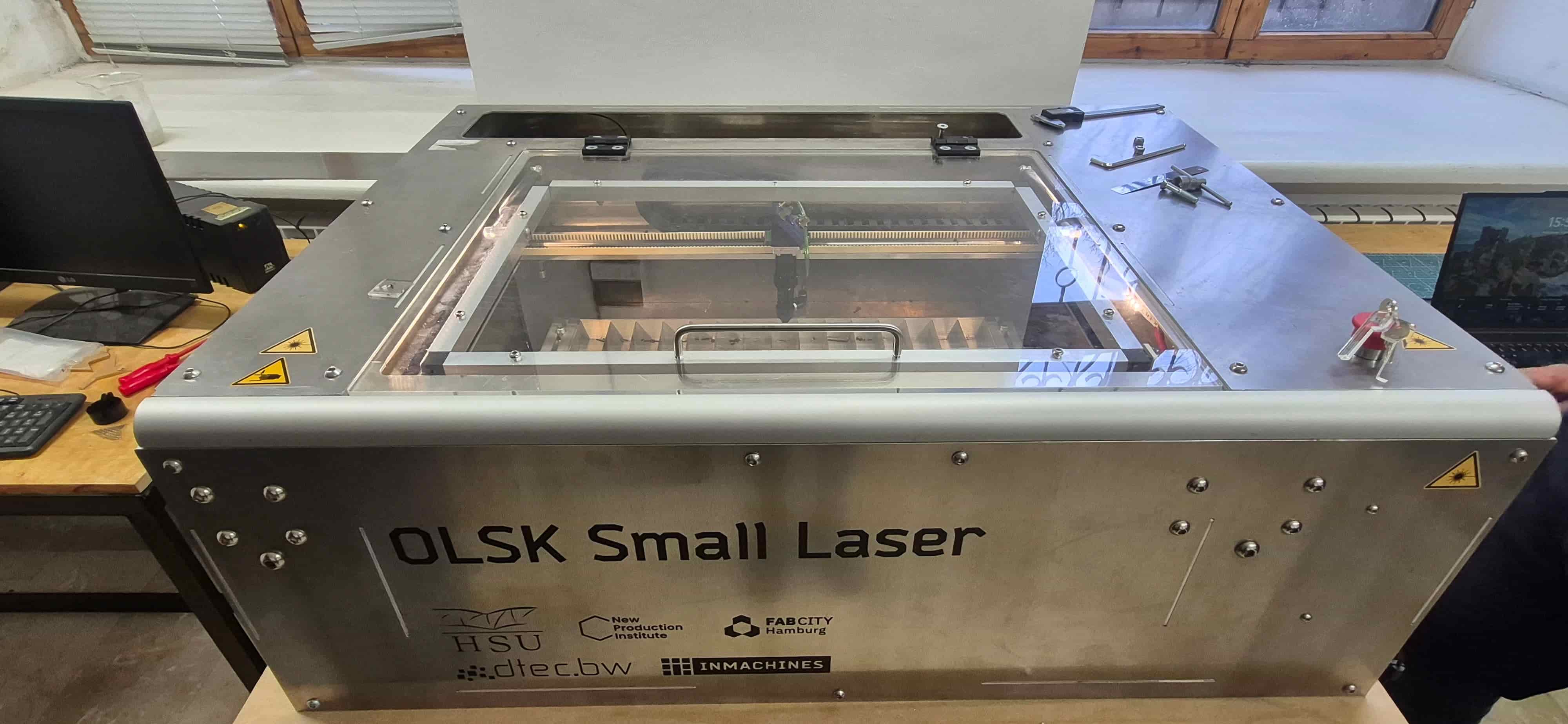
In our lab, the primary laser cutter is a Chinese CO2 laser cutter with CNC, with 80 Watts of power and a working area of 600x400mm.
| Feature | Specification |
|---|---|
| Country | China |
| Model | Kimian 6040 |
| Controller | RDC6445GZ |
| Laser Type | CO₂ |
| Laser Power | 80W |
| Work Area | 600mm x 400mm |
| Max Cutting Depth | 8mm-9mm |
| Supported Materials | Wood, Acrylic, Leather, etc. |
| Max Speed | 500mm/s |
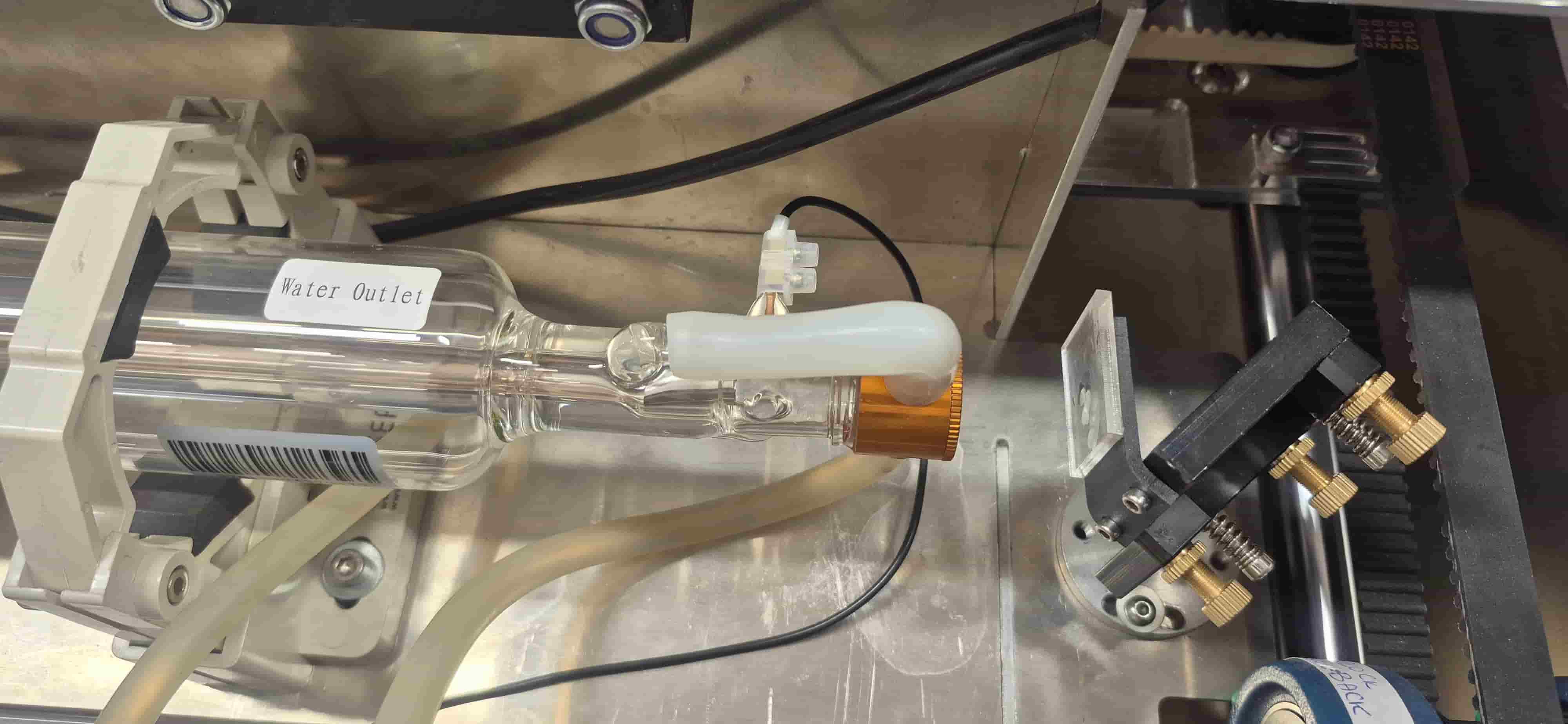
| Cooling System | Water |
| Software Compatibility | RDWorks, Lightburn |
| File Formats | SVG, DXF, AI, PDF, etc. |
| Connectivity | USB, Ethernet |
| Power Supply | 220V |
Safety Measures
In our lab, we use a Chinese 80W CNC CO2 laser cutter with a working area of 600x400mm. This machine is an important tool for precise cutting and engraving, but it requires strict adherence to safety protocols to prevent potential hazards.
Safety Precautions and Training All students have been trained in the safety precautions and proper use of the laser cutter. During training sessions, we discussed the basic rules to avoid dangerous situations and respond to potential problems. Basic recommendations include:
-
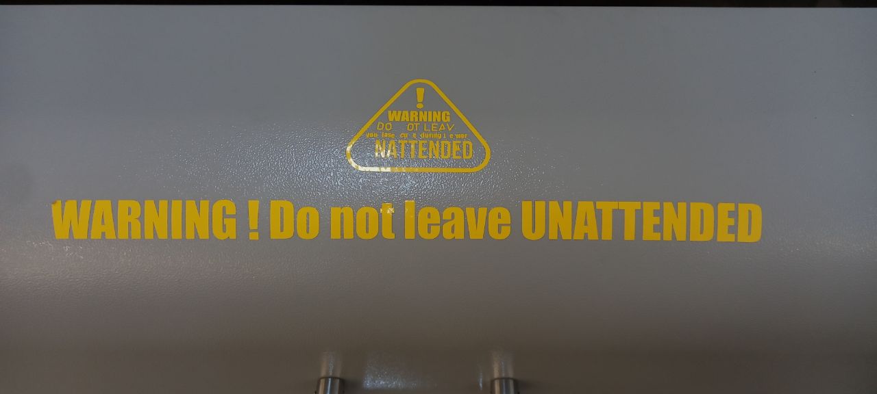
Supervision: Never leave the laser cutter unattended while it is operating.
-
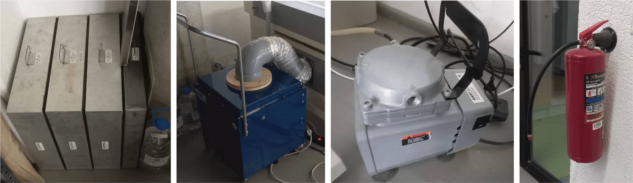
Fire extinguisher: Make sure a properly maintained and tested fire extinguisher is easily accessible.
- Air supply system: Always turn on the air supply system to reduce the risk of material combustion and improve the cutting quality.
-
Air Filtration: Use air filters to minimize harmful fumes.
-
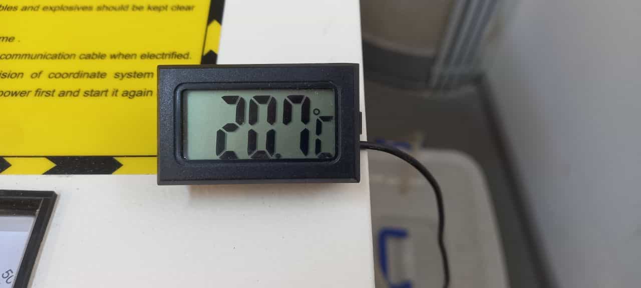
Water cooling system: Turn on the water cooling system before starting the laser. The water temperature should not exceed 35 °C to prevent overheating.
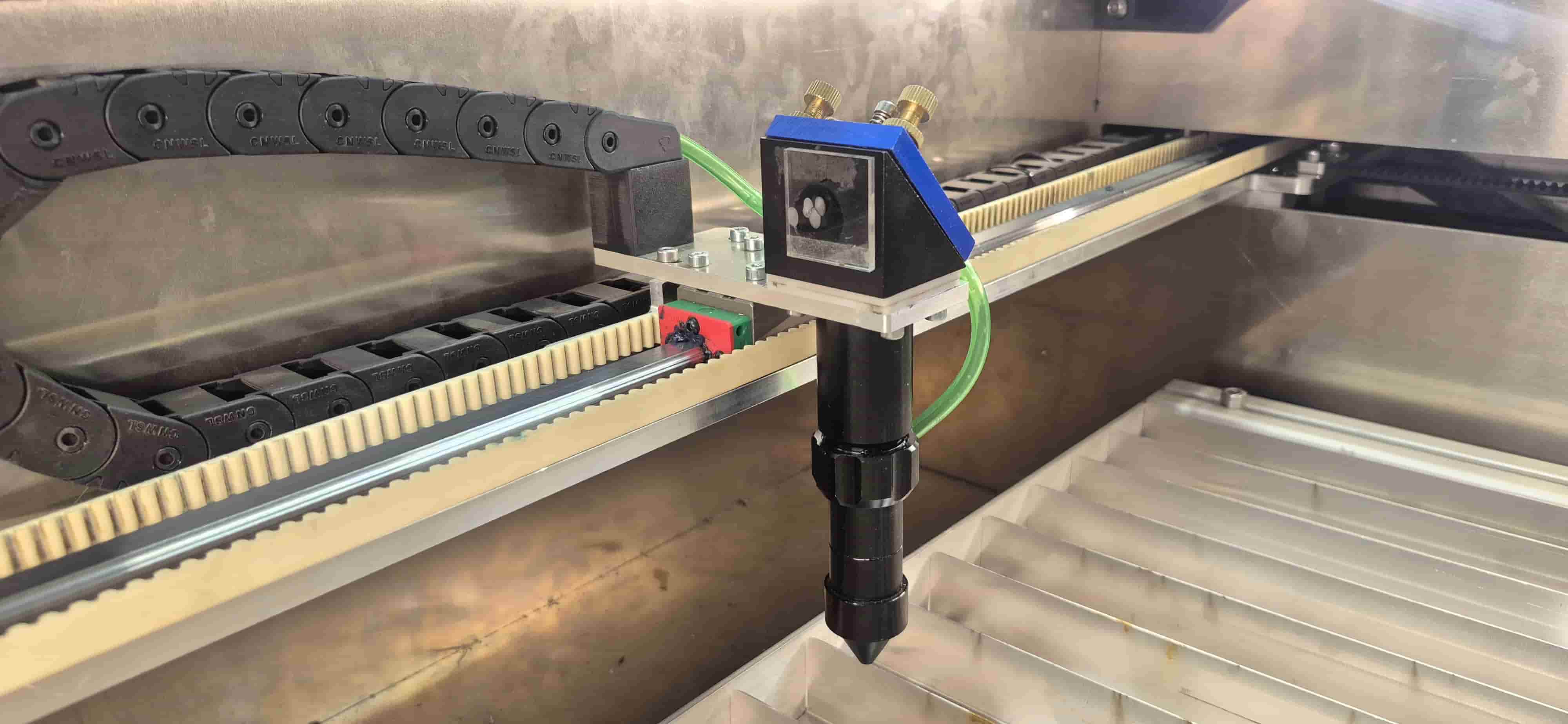
Focusing
Focusing the laser on this laser cutter is done manually.
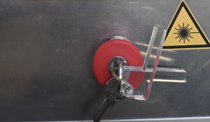
There’s a specific button, the Laser Switch, to turn on the laser.
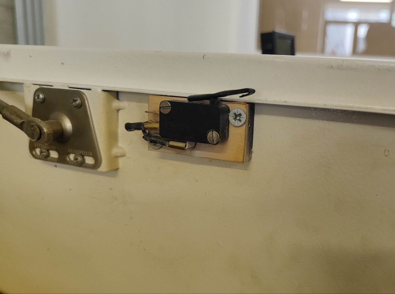
In normal mode, if the button is activated, a regular red beam is emitted, which aids in laser focusing.
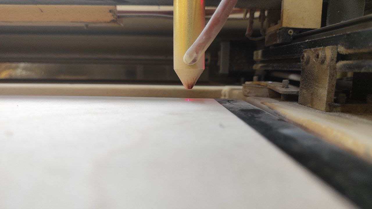
On the side of the laser cutter, there are two buttons for raising and lowering the table.
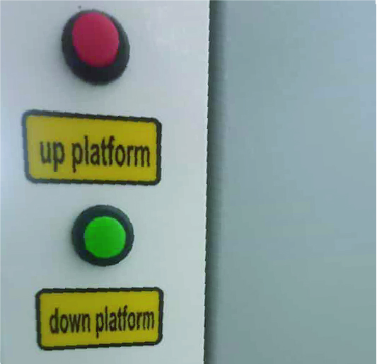
Using these buttons, the table should be adjusted so that the red beam is centered:
Measuring the kerf
We also measured the kerf of our Laser cutter. First we did a bit of research. The kerf is the portion of material that is burnt away by the laser beam. We learnt that the kerf depends on several factors, among them the focus and type of material.
We measured it for cardboard of approx. 3mm using this technique:
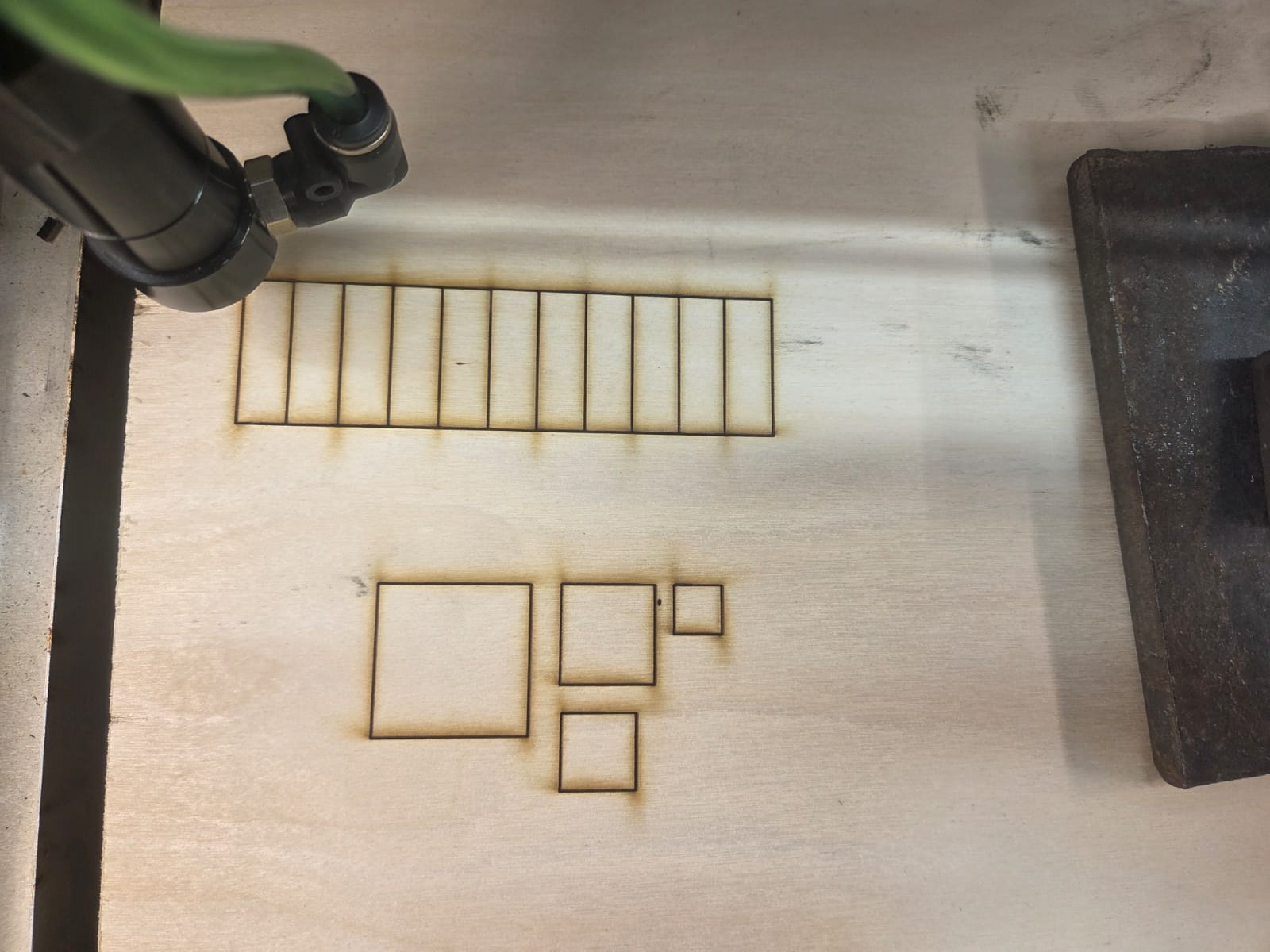
First, we designed and cut an array of small rectangles:
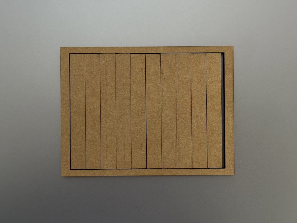
Then, we measured the width of the large rectangle remaining after removing the small rectangles:
Then, we measured the width of the small regtangles together:
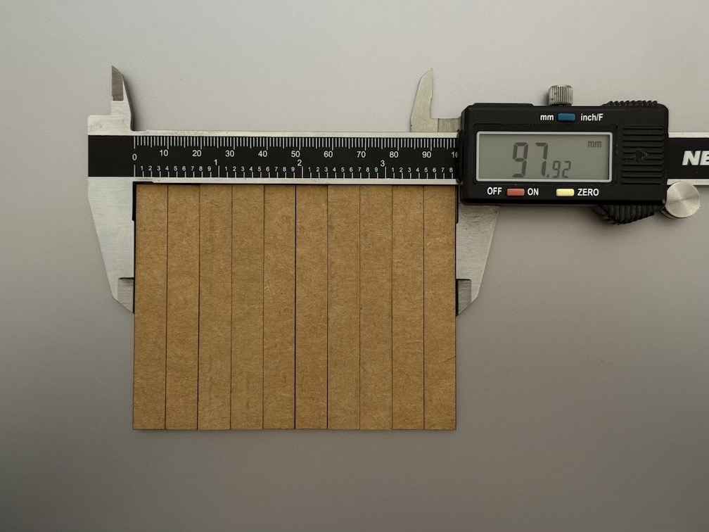
The difference between the two measurements has then to be divided by the number of “beams” used to cut the rectangles:
Therefore, our kerf = 0.23mm
Gyumri lab
This week we started by familiarizing ourselves with the laser cutter — its structure and safety rules — before moving to hands-on work.
Equipment
The Gyumri lab is equipped with two Fabulaser laser cutters.
Safety Rules
Before operating the laser cutter, we went over the following safety requirements:
-
Never leave the machine unattended while it is running
-
Always make sure the ventilation system is on before starting
-
Do not open the lid during operation
-
Avoid cutting materials that produce toxic fumes (PVC, etc.)
-
Keep the work area clear of flammable materials
-
Know the location of the emergency stop button
Beam Alignment Check
To verify the laser beam position, we used a transparent acrylic sheet rather than paper.
Acrylic lets you see the beam impact point clearly without producing excessive smoke. Paper was avoided because it could burn through and send smoke toward the mirrors, potentially damaging or contaminating the optics. We checked the beam at multiple points along the optical path.
Mirror Calibration
The laser needed calibration before we could proceed. We were assisted by Aram Pichikyan, a lecturer at the Gyumri branch of the Armenian State Academy of Fine Arts. Using the alignment screws on each mirror module, the beam was adjusted to travel through the center of the optical path and reach the cutting head precisely. The process was repeated until the beam consistently hit the target points.
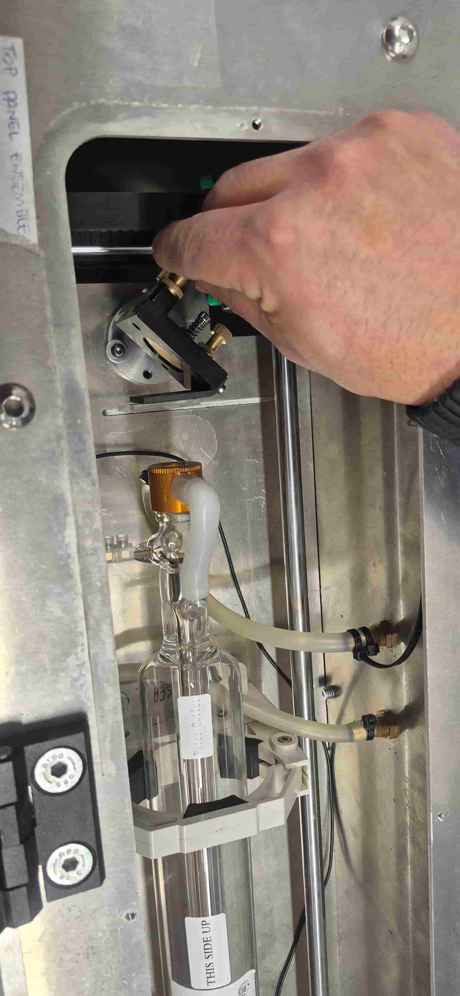
After calibration, we confirmed that the optical path was correctly aligned and the machine was ready for accurate, safe operation.
Focus Characterization
Clean, precise cuts depend on the laser being properly focused on the material surface.
The lens installed in our machine has a standard focal length of 50.8 mm (2 inches). To set the focus, we used a calibration tool with a height of 6 mm.
Here is the calibration tool we used:
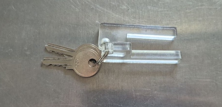
It was placed on top of the material, and the laser head was lowered until it touched the tool:
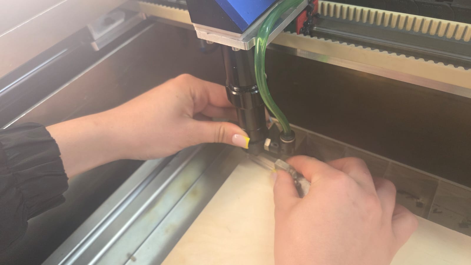
This gave us a consistent, repeatable working distance between the nozzle and the material surface, without needing to measure or guess the distance by eye each time.
Axis Calibration Issue
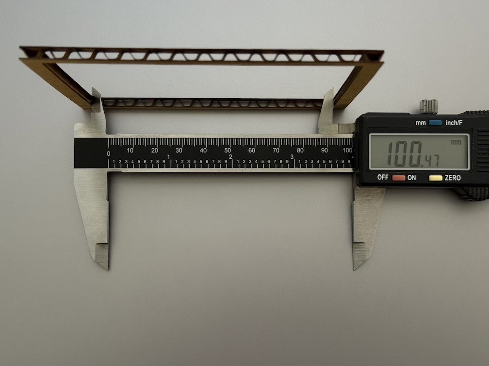
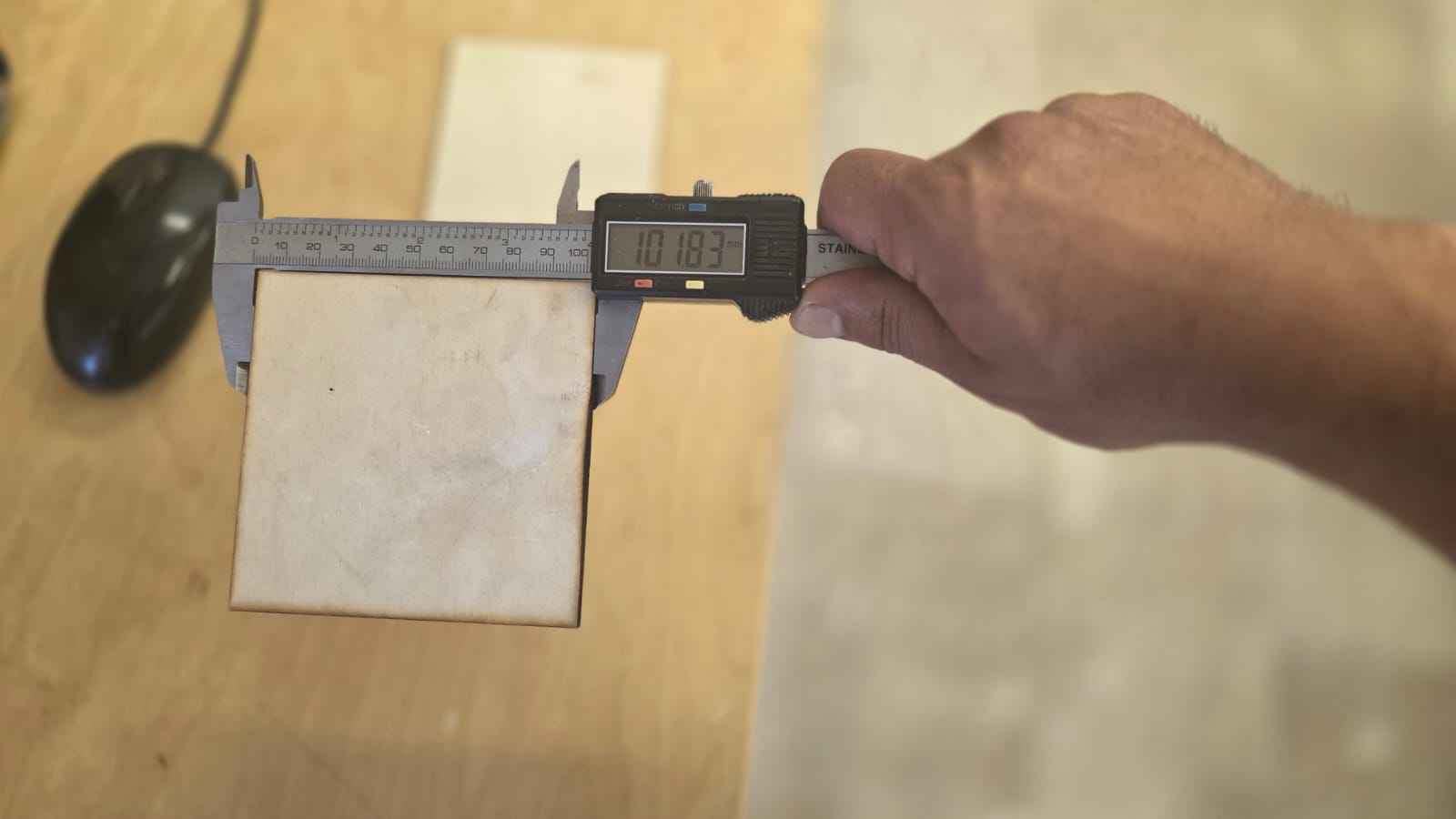
While running the laser kerf test, we noticed that the cut parts came out larger than the intended length, which is not normal — they should have come out smaller, since the kerf reduces the part’s length. This result pointed directly to a problem with how the machine’s X and Y axes were scaled. To investigate, we cut a square with a side of 100 mm and got a length of 101.83 mm along X:
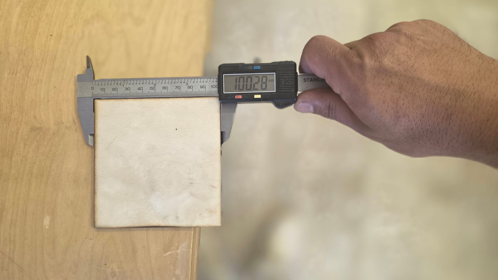
and 100.28 mm along Y:
Temporary Adjustment
For the laser located in the Dilijan lab, a part comes out about 0.15 mm smaller than its size on the drawing — so a 100 mm square is expected to come out at around 99.85 mm.
When we cut and measured our test square, we got 101.88 mm along X and 100.28 mm along Y. Accounting for the 0.15 mm shrinkage, the actual axis movement during the cut was:
- X: 101.83 + 0.15 = 101.98 mm
-
Y: 100.28 + 0.15 = 100.43 mm For the actual movement to be 100 mm, the drawn length needed to be reduced:
-
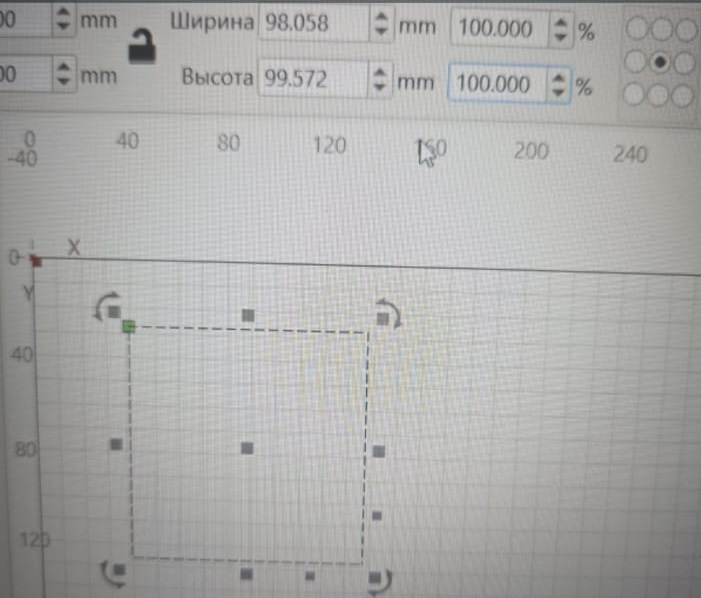
X: (100 / 101.98) × 100 = 98.058 mm
- Y: (100 / 100.43) × 100 = 99.572 mm Expressed as a percentage, this gives 98.058% along X and 99.572% along Y. We applied these percentages to the object’s width and height in LightBurn as a temporary correction.
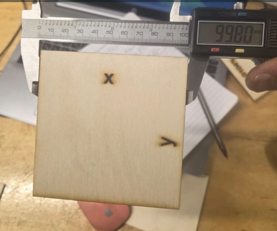
In the end, this gave a result of 99.80 mm along X:
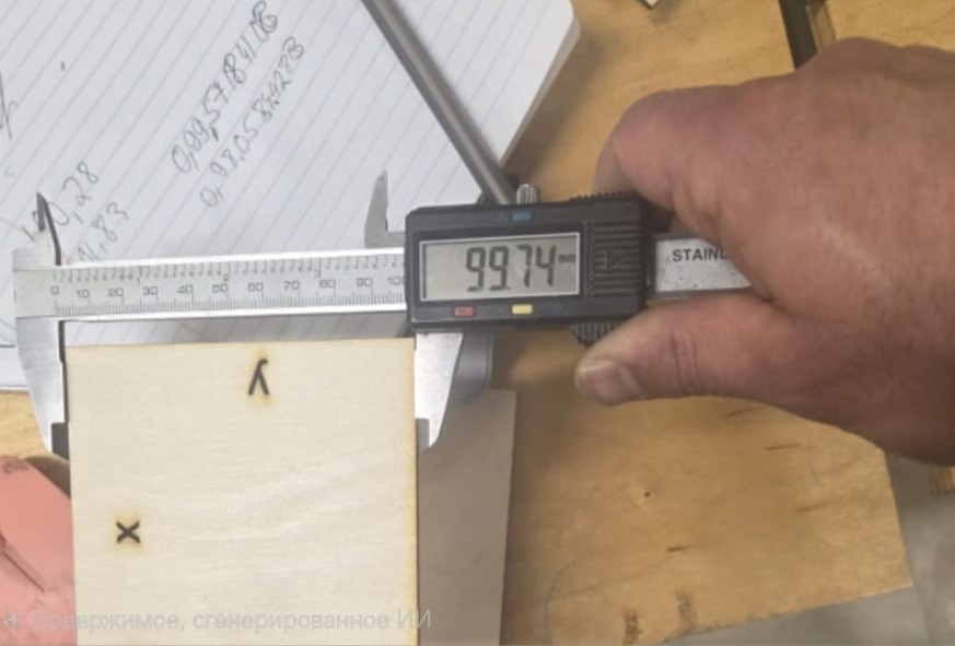
and 99.74 mm along Y:
This compensated for the axis error on a per-file basis, but it was only a workaround — it had to be reapplied for every new design rather than fixing the underlying issue.
Final Calibration
Aram Pichikyan recalibrated the machine through its GRBL configuration, adjusting the axis movement settings so that the steps taken by the stepper motors correctly corresponded to the real distance traveled. This was the permanent fix: unlike the temporary LightBurn scaling, it corrected the axis behavior at the machine level, so no per-file compensation was needed afterward. After this calibration, the machine’s movement accuracy was restored to normal.
Engraving and Cutting Tests
With the machine properly calibrated, we created test samples to identify the optimal engraving and cutting settings for two materials: 3 mm plywood and 2.7 mm acrylic.
Cutting Tests
For plywood, we kept the power fixed at 70% and varied the speed, since the goal was to find the lowest power at which a clean cut is still achieved, rather than simply running the laser at full power.
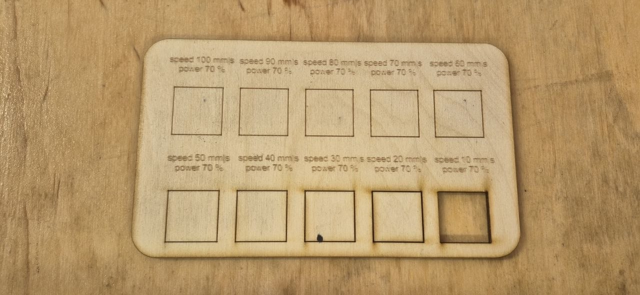
At 70% power / 10 mm/s, the plywood was cut through cleanly. At 20 mm/s, the same power was no longer enough to cut through the material. Since these two speeds differ by a factor of two, the exact speed at which the cut transitions from incomplete to complete falls somewhere between them — a finer test with intermediate speed steps would be needed to locate that boundary more precisely.
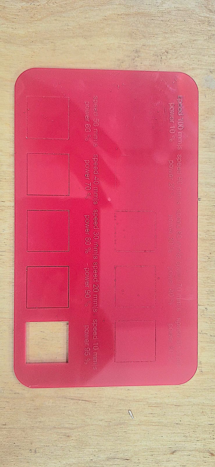
For acrylic, the test varied both speed and power together rather than fixing one parameter, which makes the result less systematic to interpret cut quality from. Even so, a working cutting setting was identified at 95% power / 10 mm/s, which cut cleanly through the 2.7 mm acrylic.
Engraving Tests
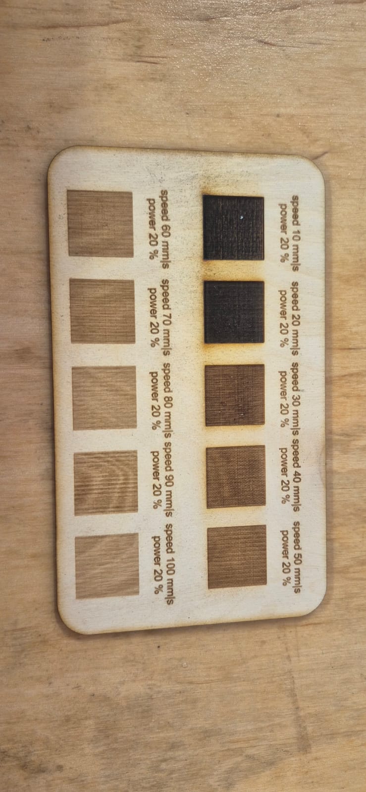
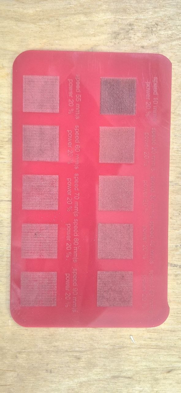
For engraving, the power was fixed at 20% on both materials, and only the speed was varied.
On plywood, we tested speeds of 10, 20, 30, 40, 50, 60, 70, 80, 90, and 100 mm/s. Visible scorching (a darkened, burnt square) appeared at 10 mm/s and 20 mm/s — these speeds left the laser dwelling too long at this power, charring the surface rather than producing a clean engraving mark.
On acrylic, we tested speeds of 10, 20, 30, 40, 50, 55, 60, 70, 80, and 90 mm/s. Visible darkening only occurred at 10 mm/s; at all higher speeds the engraving mark stayed within the expected frosted appearance without burning.
Kerf Measurement
After the axis calibration was completed, we ran a kerf test using a calibration pattern of 11 rectangles (10 mm each), cut as a single continuous geometry.
Expected total length: 110 mm Measured total length: 107.77 mm
Since the test consisted of 11 rectangles, there are 10 cuts between them, plus half a kerf width lost on each outer edge — giving 11 effective kerf widths in total:
This kerf value of approximately 0.20 mm is the one we adopted for joint and parametric design calculations going forward.