Machine Building Group 2
Project name
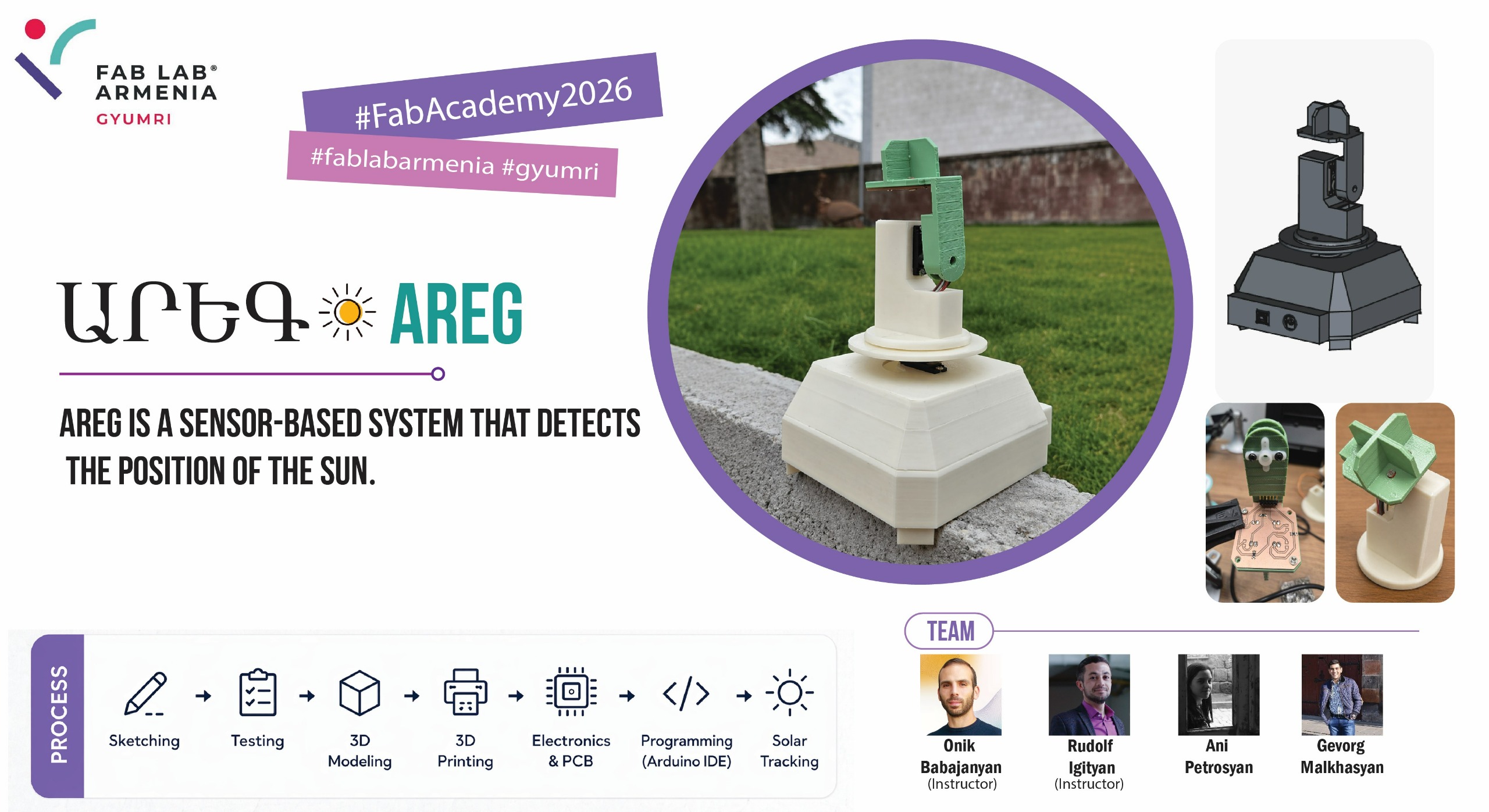
We named our solar tracker Areg (Արեգ), an Armenian male name that literally translates to Sun, perfectly reflecting the core purpose of our device
Slide and Video
Members
Students
- Gevorg Malkhasyan — Sensor PCB development, 3D modeling (upper section), 3D printing, Assembly (top section), Coding → Week 12 individual page
- Ani Petrosyan — 3D modeling (lower section), 3D printing, Assembly (bottom section), Coding → Week 12 individual page
Instructors
-
Onik Babajanyan - Project idea
-
Rudolf Igityan - Project implementation
Task Planning and Allocation
We divided the work by subsystem, so each person owned a specific part of the machine end-to-end.
| Task | Gevorg | Ani |
|---|---|---|
| Concept sketches | ✅ | |
| Sensor PCB — schematic | ✅ | |
| Sensor PCB — layout and milling | ✅ | |
| 3D modeling — upper section (sensor arm, wire routing) | ✅ | |
| 3D modeling — lower enclosure (Arduino Uno + horizontal servo) | ✅ | |
| 3D modeling — connecting piece | ✅ | |
| 3D printing — upper parts | ✅ | |
| 3D printing — lower parts | ✅ | |
| Assembly — top section (PCB mount, sensor soldering, vertical servo) | ✅ | |
| Assembly — bottom section (Arduino Uno, horizontal servo, wiring) | ✅ | |
| Assembly — joining the two sections | ✅ | ✅ |
| Programming — sensor reading, servo logic, threshold, refactoring | ✅ | ✅ |
Light Sensor Selection
Since a photoresistor (LDR) changes its resistance depending on the amount of light hitting it, it is well suited for our task.
Reading a Photoresistor with a Microcontroller
This raises the question: how do we read its value using a microcontroller?
The microcontroller supplies voltage to the photoresistor. However, if we read the voltage at the input side of the LDR, we always get 5V; if we read it at the output side (after the LDR, just before GND), we always get 0V — all the voltage has already dropped across the load. Neither reading is useful.
The solution is a voltage divider. By placing a fixed resistor in series with the photoresistor, we create two voltage drops — one across each component. If we connect the microcontroller’s analog pin to the midpoint between them, we get a reading that changes with the LDR’s resistance.
Since the microcontroller shares a common GND with the rest of the circuit, its analog pin effectively acts as a voltmeter — reading a value between 0 and 1023, where 0 corresponds to 0V and 1023 corresponds to 5V.
Circuit Schematic
        5V
         |
        [R1]  ← fixed resistor (1 kΩ or 10 kΩ)
         |
         +──────────→ Analog pin (A0–A3)
         |
        [LDR]  ← photoresistor
         |
        GND
The fixed resistor R1 is placed first (closest to 5V), and the LDR second (closest to GND). This means the analog pin reads the voltage drop across the LDR.
Since the LDR’s resistance decreases in brighter light, the voltage across it also decreases, so lower analog values = more intense light. The relationship is inverse. Swapping the order of R1 and LDR would give a direct proportional relationship instead.
Choosing the Right Fixed Resistor
Rather than simply looking up the answer online, we decided to investigate the choice of resistor more deeply. Since most programming and calibration would take place indoors, we measured the LDR’s resistance in two conditions:
| Condition | LDR resistance |
|---|---|
| Room light | ~1 250 Ω |
| Covered (dark) | ~20 000 Ω |
We then considered two candidate resistors: 1 kΩ and 10 kΩ.
Calculations
For a series circuit with supply voltage 5V, by Ohm’s law the current through both components is the same:
The analog pin reads the voltage drop across the LDR only:
The Arduino ADC maps 0–5V linearly onto 0–1023. Combining both steps gives a single formula for the analog reading:
Case 1 — R1 = 1 kΩ, in light (R_LDR ≈ 1 250 Ω):
Case 2 — R1 = 1 kΩ, in darkness (R_LDR ≈ 20 000 Ω):
Case 3 — R1 = 10 kΩ, in light (R_LDR ≈ 1 250 Ω):
Case 4 — R1 = 10 kΩ, in darkness (R_LDR ≈ 20 000 Ω):
Results
| Condition | R1 = 1 kΩ | R1 = 10 kΩ |
|---|---|---|
| In light (LDR ≈ 1 250 Ω) | ~568 | ~114 |
| In darkness (LDR ≈ 20 000 Ω) | ~975 | ~682 |
| Spread (dark − light) | 407 | 568 |
Final Choice: 10 kٶ
We selected the 10 kΩ resistor. With this configuration, the analog values are immediately intuitive: values below approximately 500 indicate bright light, while values above 500 indicate darkness. The threshold sits near the midpoint of the 0–1023 scale, making the readings easy to interpret and calibrate.
The 10 kΩ resistor also gives a wider spread between light and dark conditions, making the sensor more sensitive and easier to work with in code.
Passive Sensor Design and Fabrication
The core idea behind our solar tracker is straightforward: instead of knowing the sun’s position mathematically, the device finds it by sensing light. To determine which direction the sun is in, the system compares light intensity from four sides simultaneously — top-left, top-right, bottom-left, and bottom-right. By knowing which sensor receives the most light, the microcontroller can decide which way to rotate.
For this comparison to be meaningful, each sensor must be fixed at a precise, known position and physically isolated from its neighbours — otherwise light from one direction could reach the wrong sensor and corrupt the reading. This is why a dedicated PCB was designed to hold all four photoresistor channels at consistent, symmetric positions, and why the 3D-printed enclosure includes divider walls between them.
Schematic Design
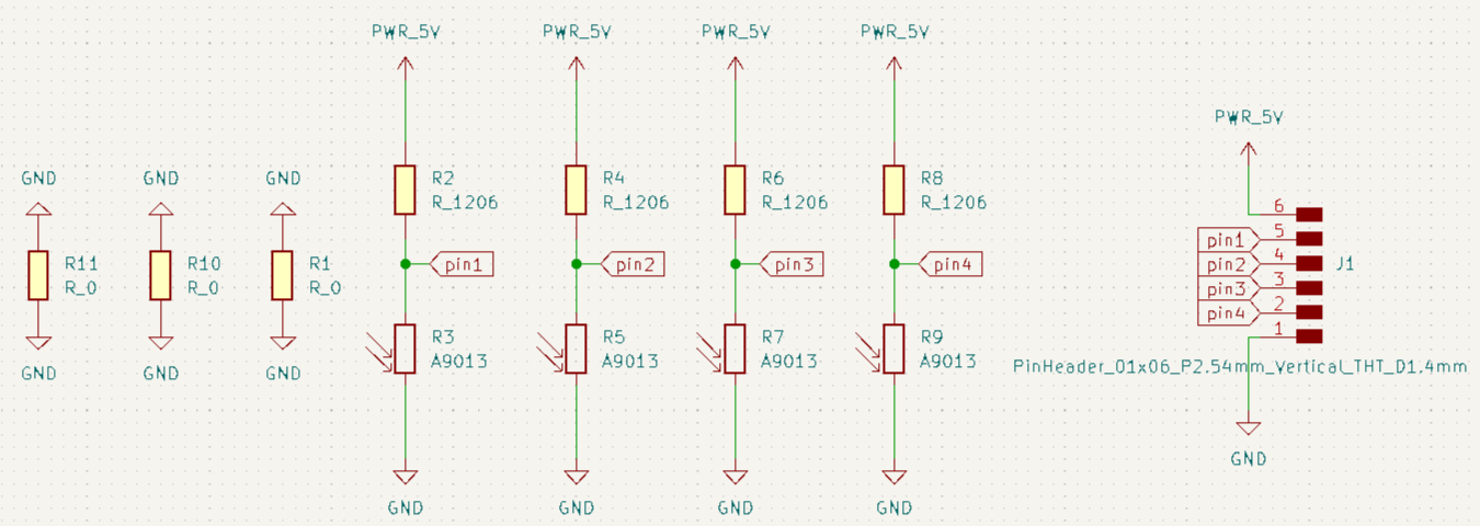
The schematic was created in KiCad and consists of four independent voltage divider channels. Each channel pairs a fixed 10 kΩ resistor (connected to 5V) with a photoresistor (connected to GND), and routes the midpoint voltage to one of four analog output pins.
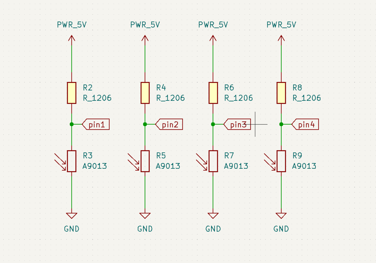
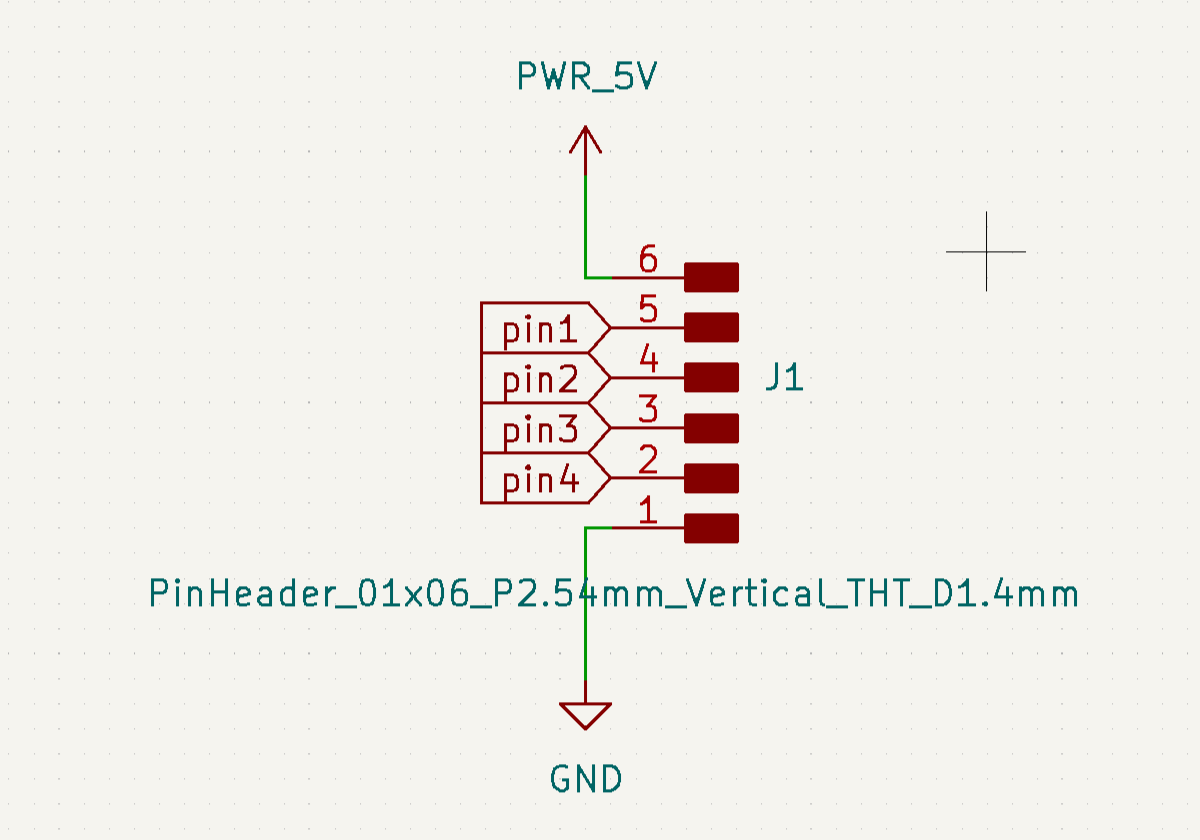
All four channels share a common power connection through a pin header, which provides a single entry point for 5V and GND. The same header exposes four signal pins — one per channel — which carry the analog voltage readings to the microcontroller.
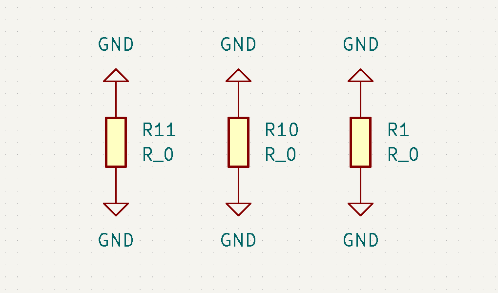
During routing, we encountered traces that could not be laid out without crossing each other. To resolve this, we added three 0 Ω resistors (R1, R10, R11) as jumpers, allowing traces to bridge over one another on a single-layer board without creating a short.
And the general shema turned out to be as follows:
PCB Design
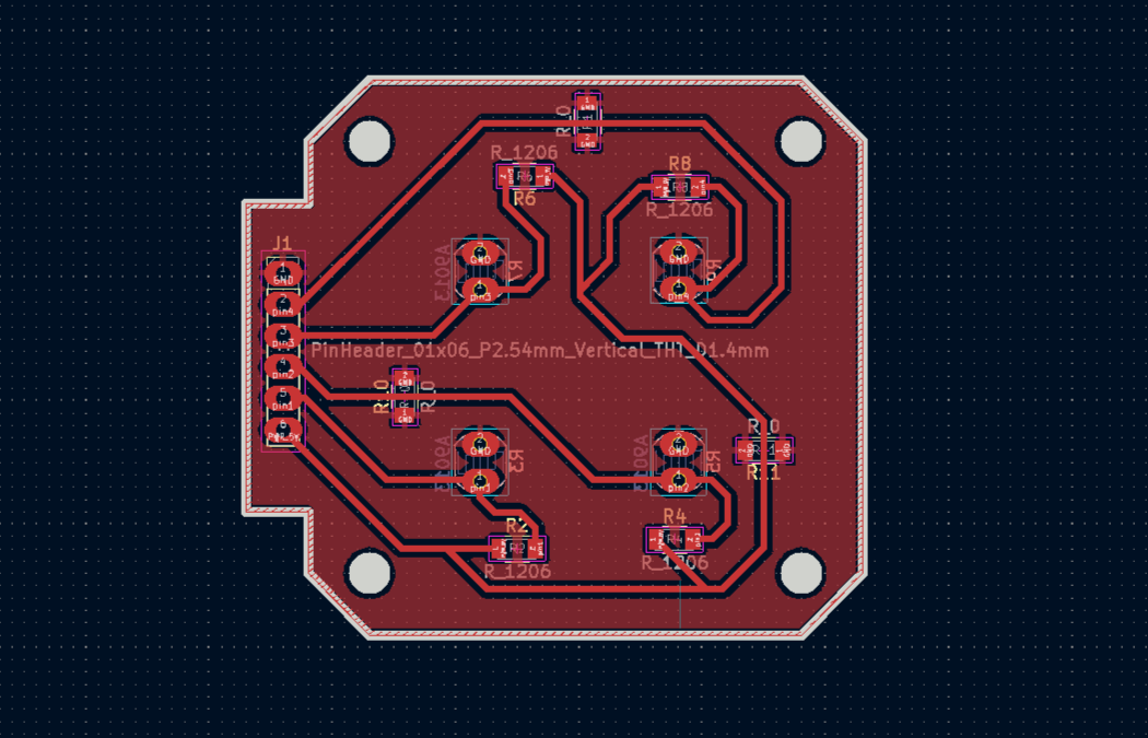
With the schematic finalised, the layout was done in KiCad.
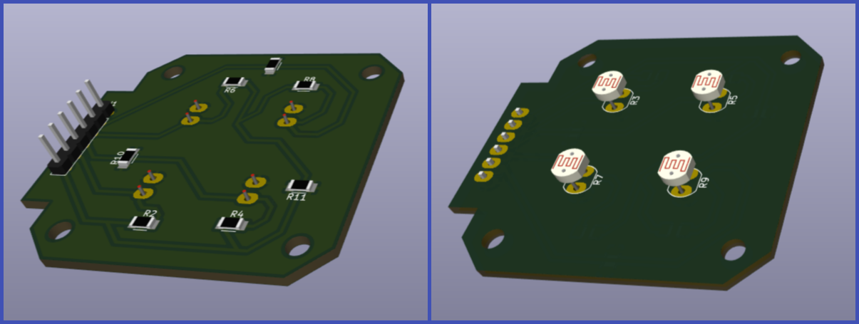
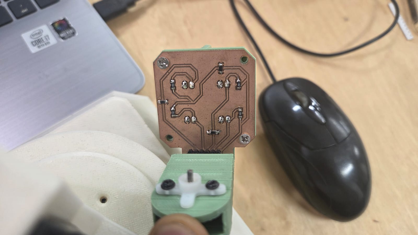
The four photoresistors were placed symmetrically. Notably, the photoresistors were placed on the back side of the board — this is intentional, as the PCB will be mounted to the enclosure from the back, positioning the sensors flush against the divider walls on the outside.
Analog signal traces were kept short to minimise noise, and power distribution — 5V and GND — was routed across the board for stable operation across all four channels. The layout also includes mounting holes at the corners for screw attachment to the enclosure:
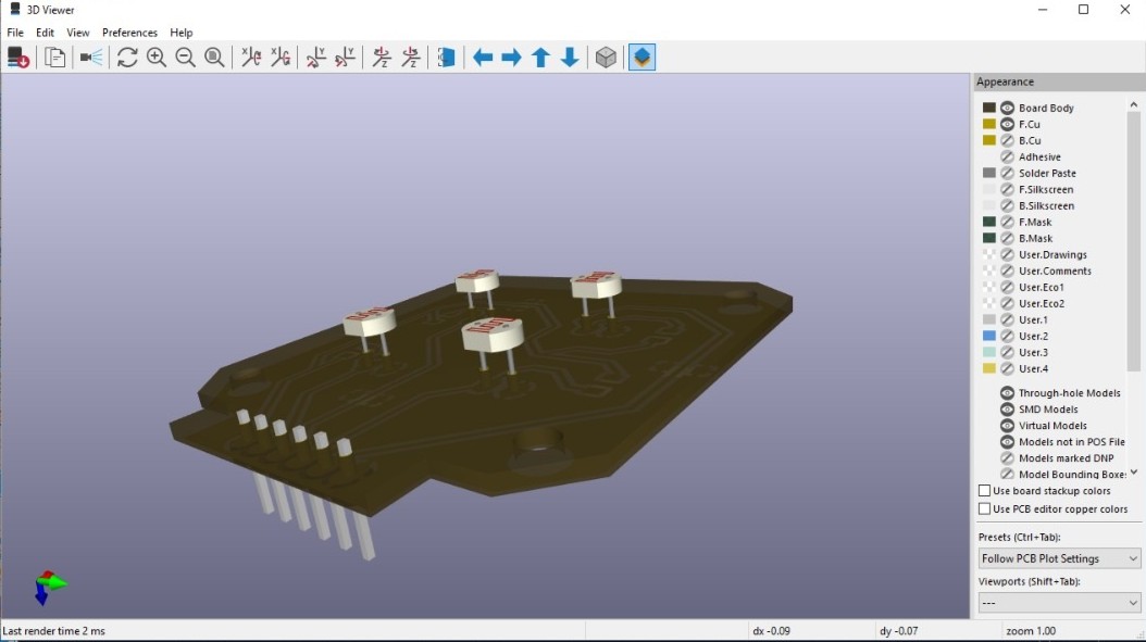
The KiCad 3D viewer was used as a final visual check before export, allowing us to verify component placement and overall board geometry before committing to fabrication.
G-code Generation
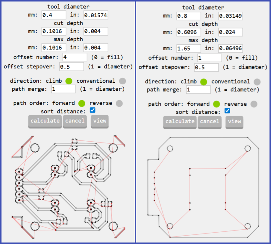
Toolpaths were generated using mods.cba.mit.edu. Two separate SVG files were exported from KiCad — one for the copper traces, and one for the board outline and holes — and each was processed independently in mods to produce two NC files:
- NC file 1 — trace isolation milling, using a 0.4 mm end mill
- NC file 2 — outline cutting and hole drilling, using a 0.8 mm end mill
Milling on the Roland SRM-20
The two NC files were run sequentially on the Roland SRM-20 desktop CNC mill. The copper-clad FR1 board was fixed to the bed, the tool was zeroed, and the trace isolation pass was run first, followed by the outline and hole pass with the larger bit.
(PHOTO — Roland SRM-20 during milling)
Soldering
After milling, all components were soldered onto the board — except the photoresistors.
The photoresistors were left unsoldered intentionally. They were only soldered after the board was mounted onto the enclosure, ensuring that each sensor sits in exactly the right position relative to the divider walls. This process is described in the Soldering the Photoresistors section of the Assembly chapter.
Servo Motor Selection
After completing the PCB design phase, we moved on to selecting the motors. We needed to provide both vertical and horizontal rotation for the system.
Comparing Specifications
We considered two different servo motors.
| Feature | HK-15138 Servo Motor | Corona DS-939MG Servo Motor |
|---|---|---|
| Image | 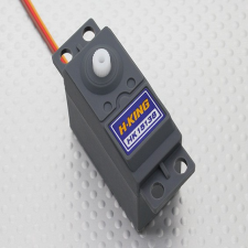 |
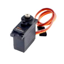 |
| Motor Type | Standard analog servo | Digital metal gear servo |
| Operating Voltage | 4.8V – 6V | 4.8V – 6V |
| Torque | ~4.3 kg.cm | ~2.5–2.7 kg.cm |
| Current | ~0.7–1 A (load dependent) | ~0.2–0.24 A (normal operation) |
| Speed | ~0.17 sec/60° | ~0.13–0.14 sec/60° |
| Gear Type | Plastic gears | Metal gears |
| Weight | ~38 g | ~12.5 g |
| Rotation Angle | ~180° | ~180° |
| Control Signal | PWM | PWM |
As an initial criterion, we looked at the torque value. In the case of the Corona DS-939MG Servo Motor, the rated torque is ~2.5–2.7 kg·cm. This figure seemed promising, as we intended to keep our device as lightweight as possible. It means the servo can rotate a 250-gram load at an arm length of 10 cm, which is well suited for our purposes.
Servo Motor Test
We didn’t stop there — it was important for us to observe the servo motor’s behavior under load firsthand.
To do this, we used a laser cutter to cut a circular disc from 3 mm plywood with a diameter of 150 mm, which allowed us to place weights on it.
We then attached the disc to the servo motor and connected it to an Arduino UNO.
We then attached the disc to the servo motor and connected it to an Arduino UNO — signal wire to pin 9, power to 5V, ground to GND.
For this test we used the official Arduino example from the Arduino servo motor documentation.
Test Code
For this test we used the official Arduino example from the Arduino servo motor documentation:
#include <Servo.h>

Servo myservo;  // create servo object to control a servo
// twelve servo objects can be created on most boards

int pos = 0;    // variable to store the servo position

void setup() {
  myservo.attach(9);  // attaches the servo on pin 9 to the servo object
}

void loop() {
  for (pos = 0; pos <= 180; pos += 1) { // goes from 0 degrees to 180 degrees
    myservo.write(pos);              // tell servo to go to position in variable 'pos'
    delay(15);                       // waits 15ms for the servo to reach the position
  }
  for (pos = 180; pos >= 0; pos -= 1) { // goes from 180 degrees to 0 degrees
    myservo.write(pos);              // tell servo to go to position in variable 'pos'
    delay(15);                       // waits 15ms for the servo to reach the position
  }
}
This code sweeps the servo continuously from 0° to 180° and back, allowing us to observe its behavior during repeated motion cycles:
Performance Under Load
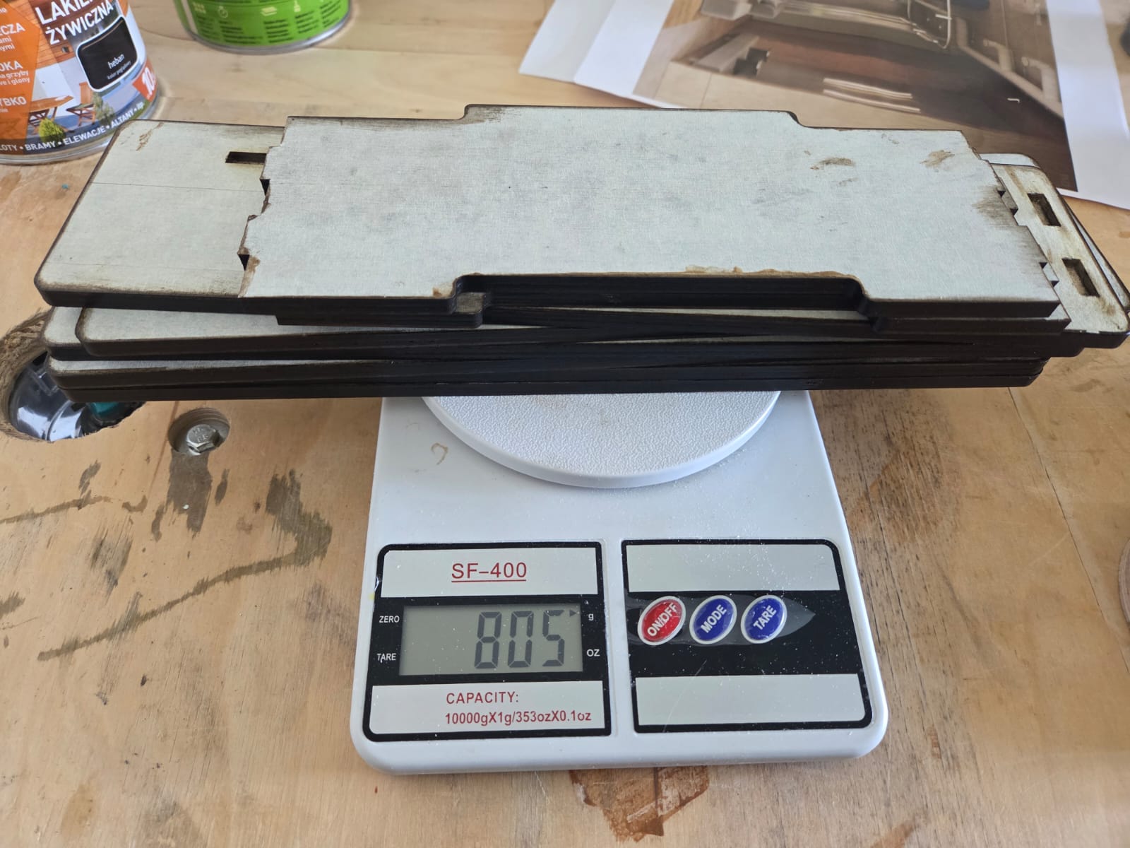
After verifying the basic motion, we began applying various weights to the servo to simulate real operating conditions. By gradually increasing the load, we were able to assess whether the motor could reliably handle the mechanical demands of our sun-tracking system:
After testing, we measured the weight of the assembly using a scale. The total weight of the upper structure came to approximately 805 grams:
Performance Under Vertical Load
We also tested an alternative load configuration, with the weight suspended vertically:
Final Selection
Based on the test results, it was clear that the servo motor could operate stably and provide the necessary range of motion even under load. These findings informed our final motor selection and confirmed its suitability for our sun-tracking system.
It is also worth noting that the Corona DS-939MG Servo Motor allows us to avoid the need for an external power supply. A single servo draws approximately 200 mA, and since we do not intend to run both motors simultaneously, the total current remains within the 500 mA that the Arduino UNO can supply through its 5V pin — more details on this can be found here.
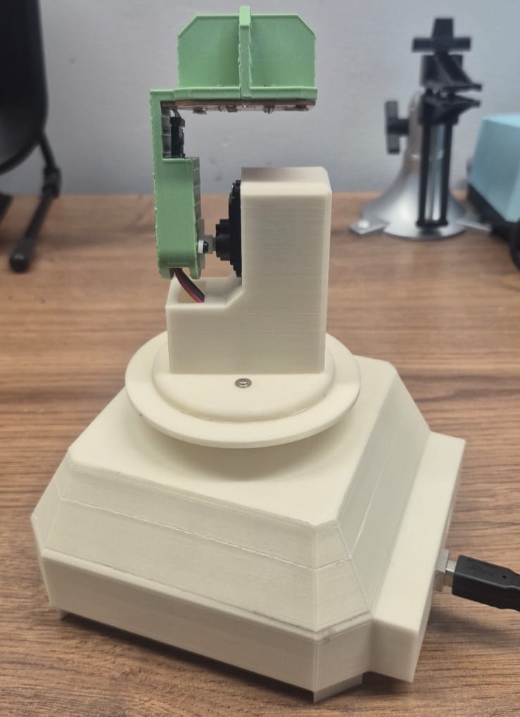
3D Modeling
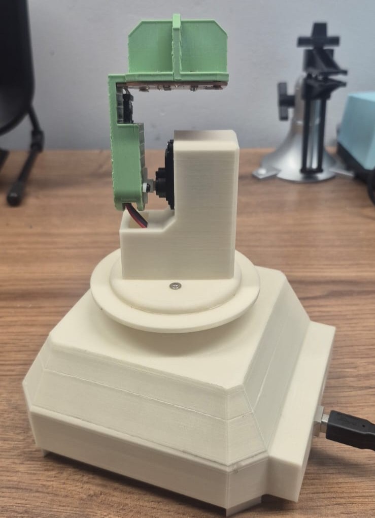
The 3D modeling work was split by section: Gevorg designed the upper part — the vertical arm that mounts on the servo shaft, holds the sensor PCB, and routes the wires to the vertical motor — while Ani designed the lower enclosure, which houses the Arduino Uno and the horizontal-axis servo motor.
We started from a hand-drawn sketch that captured the key constraints: the device had to be lightweight and compact, all wiring and mechanisms had to move freely inside without obstruction, and wires had to stay hidden from view.
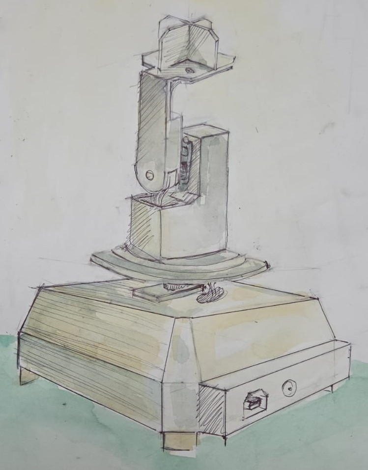
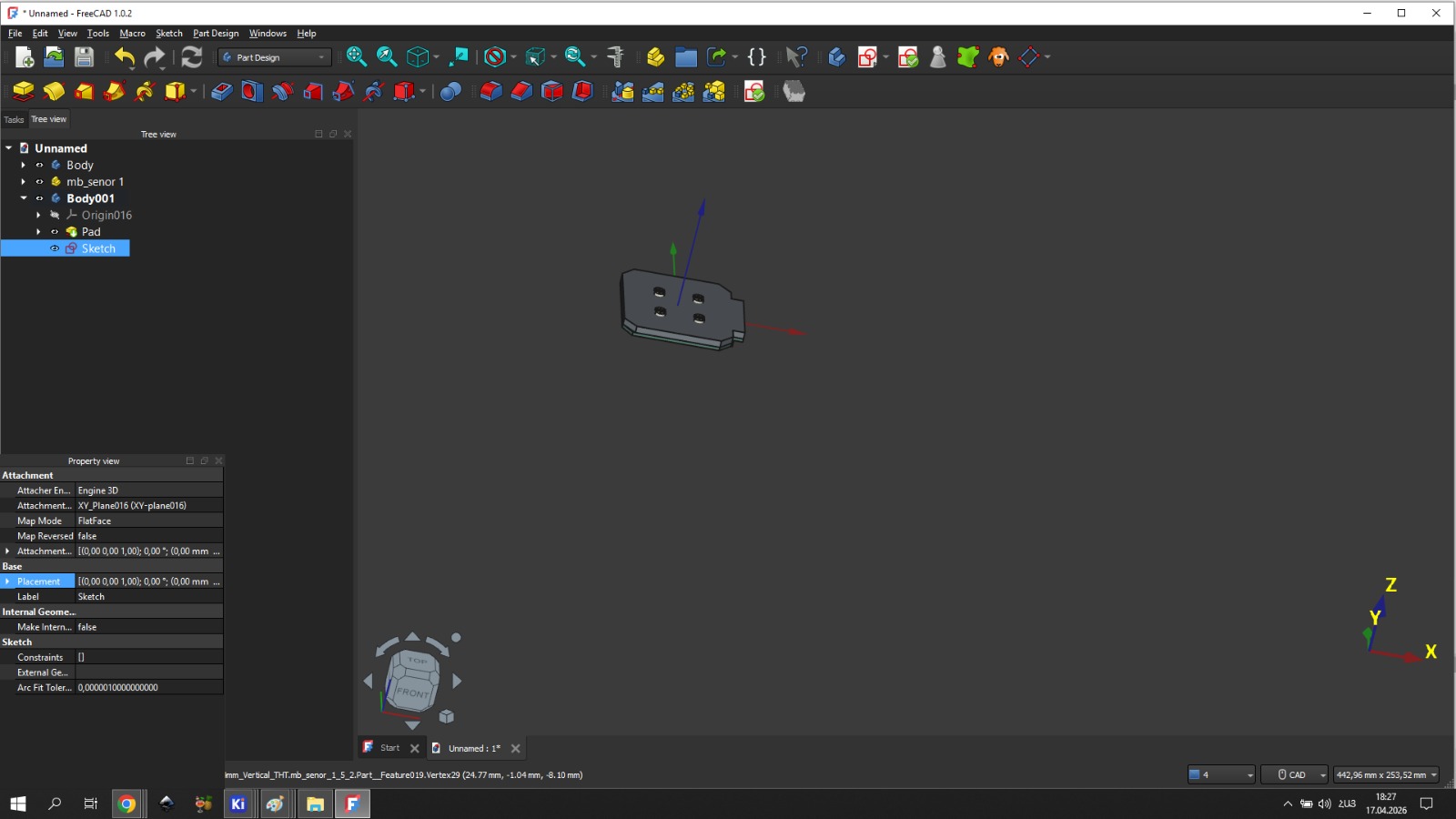
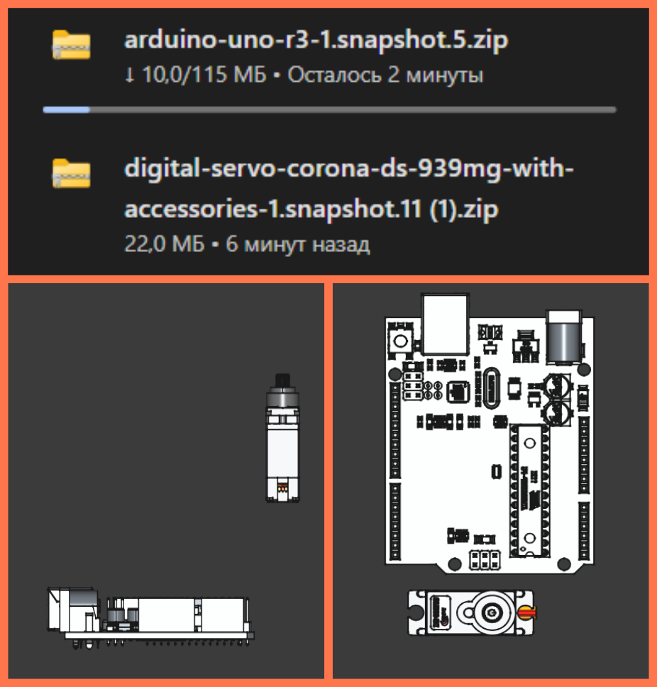
After discussing the sketch, we moved into CAD. Both of us downloaded real 3D models of the components — the sensor PCB (exported from KiCad), the Corona DS-939MG servo motor (from GrabCAD), and the Arduino Uno — and placed them directly in the modeling environment. This let us check clearances and mounting positions before committing to any geometry.
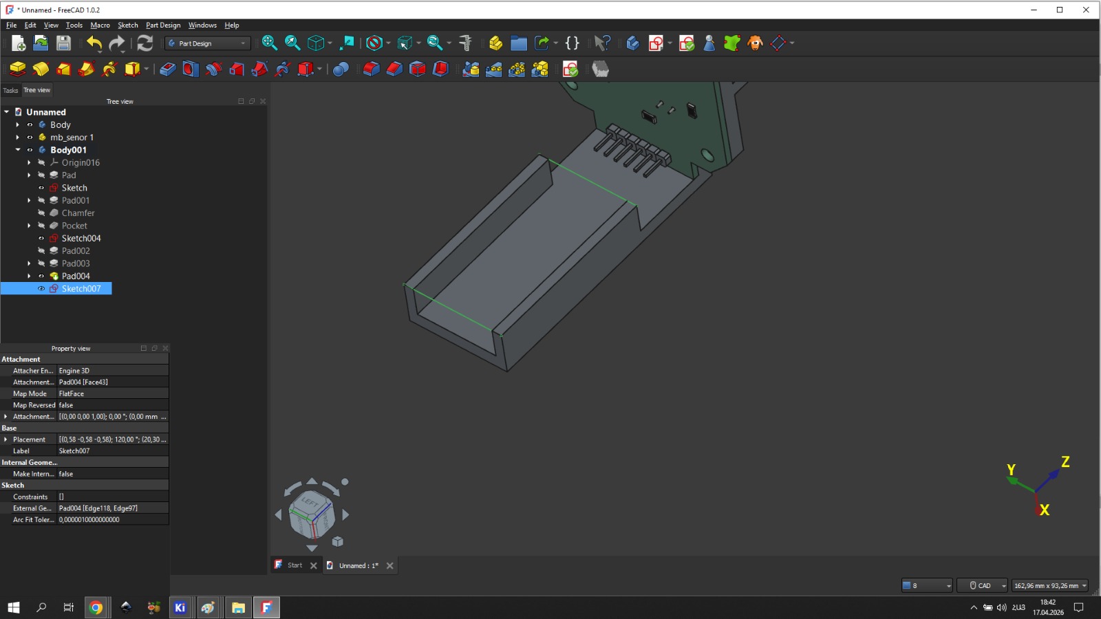
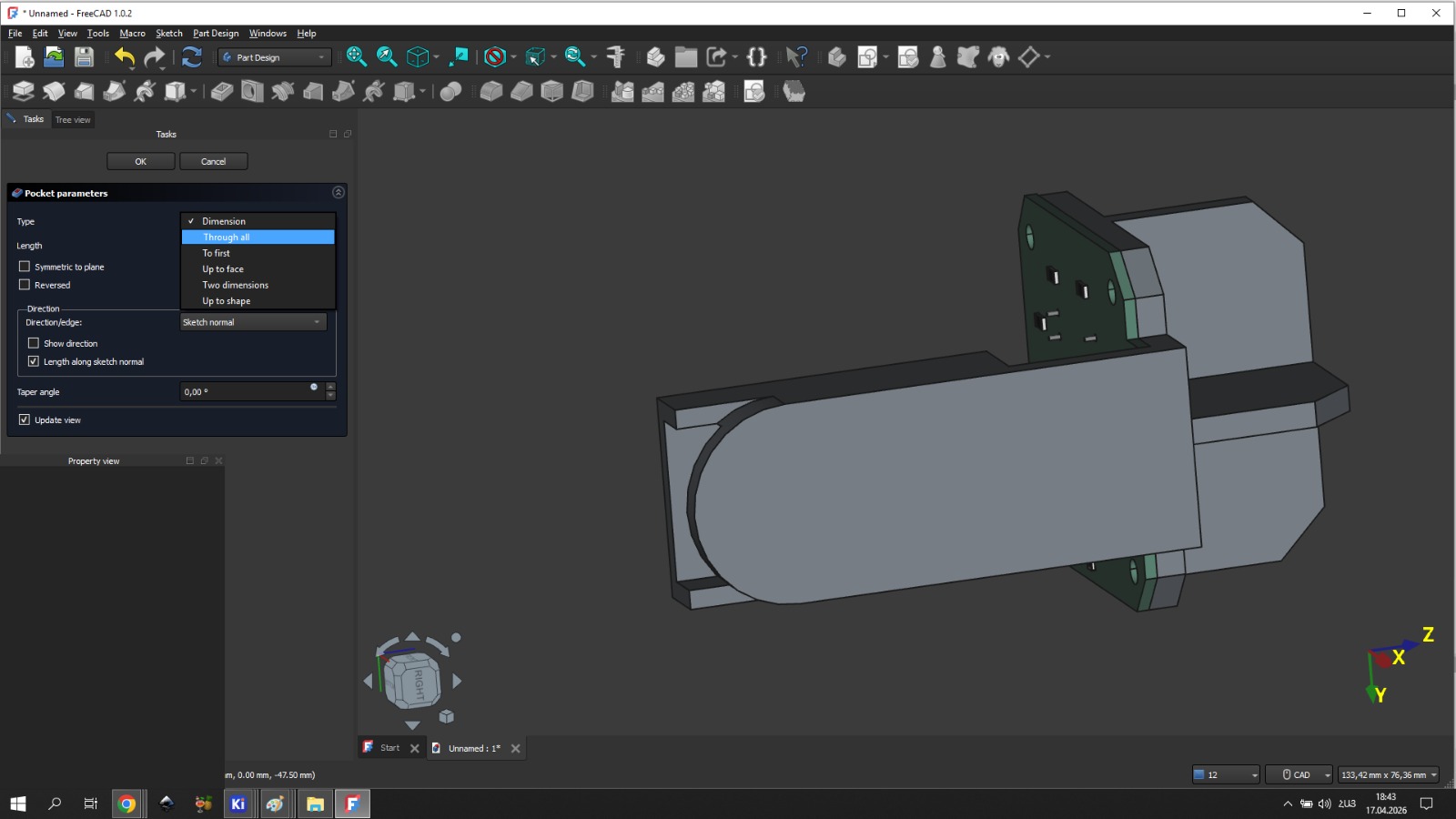
Upper Section — Gevorg
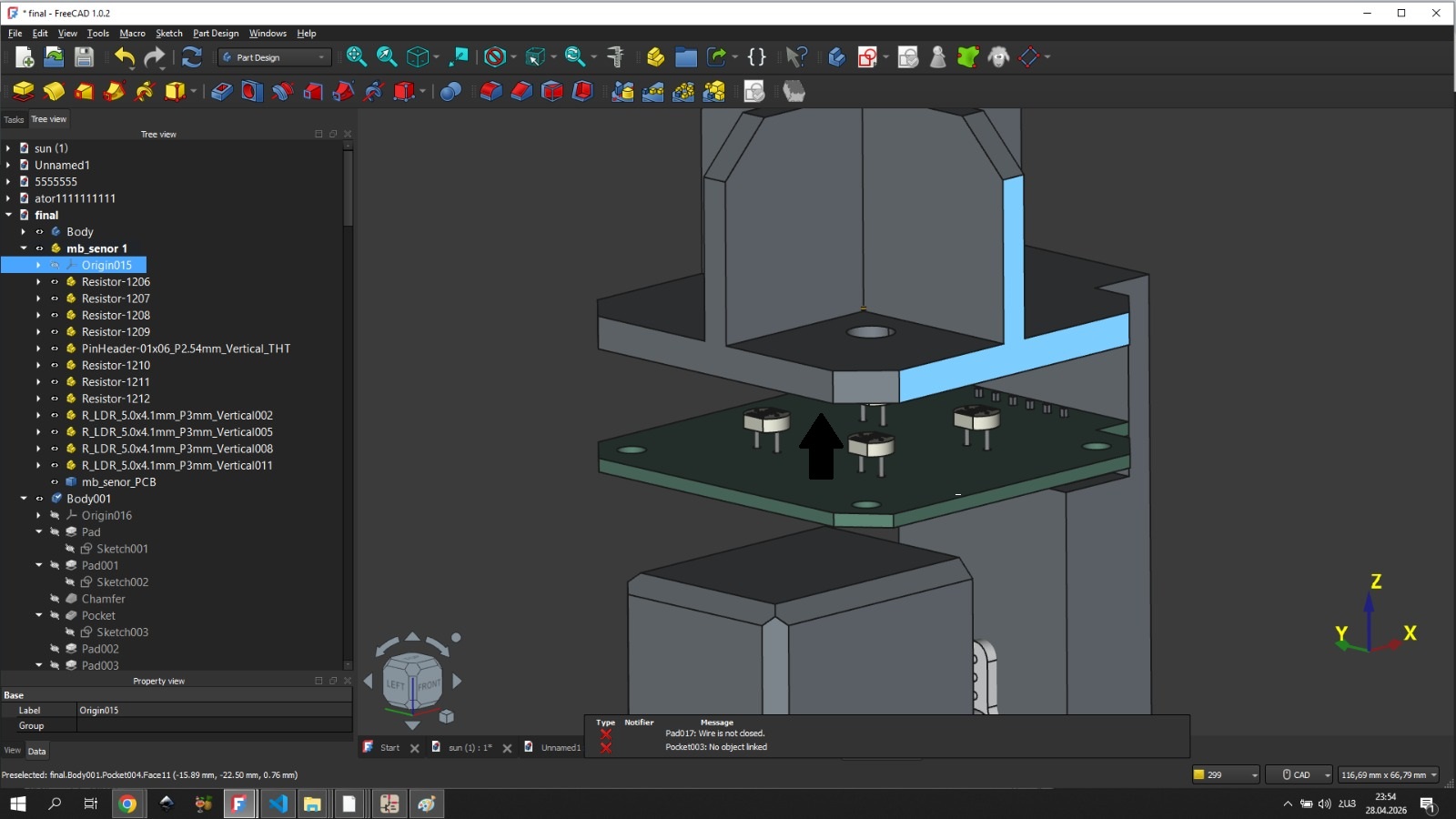
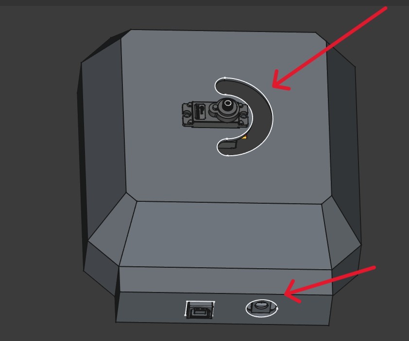
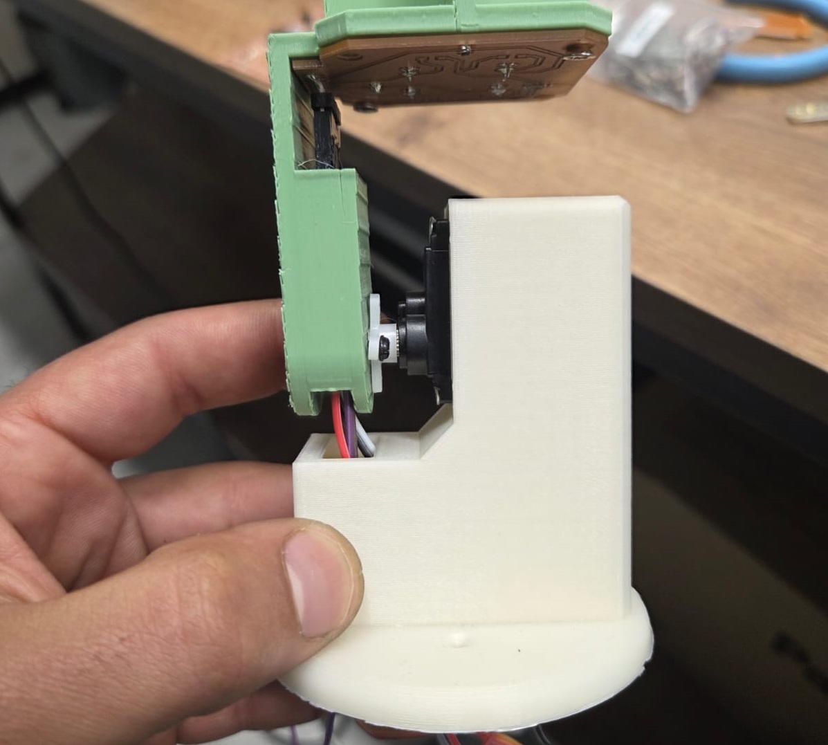
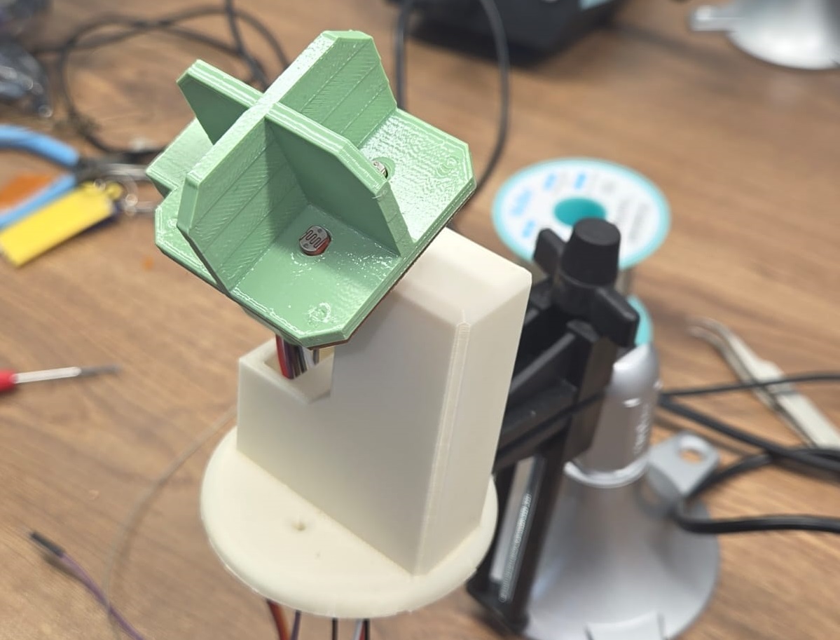
The upper section had to hold the sensor PCB at the top, with the four photoresistors flush against the divider walls, and route wires down through the arm to the vertical servo motor below.
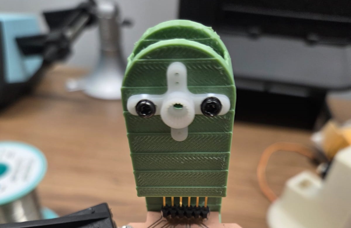
The PCB sits at the bottom of the sensor head so that the photoresistors, inserted from the opposite side, project outward through the holes and face the light directly. All pin connections are made from the bottom.
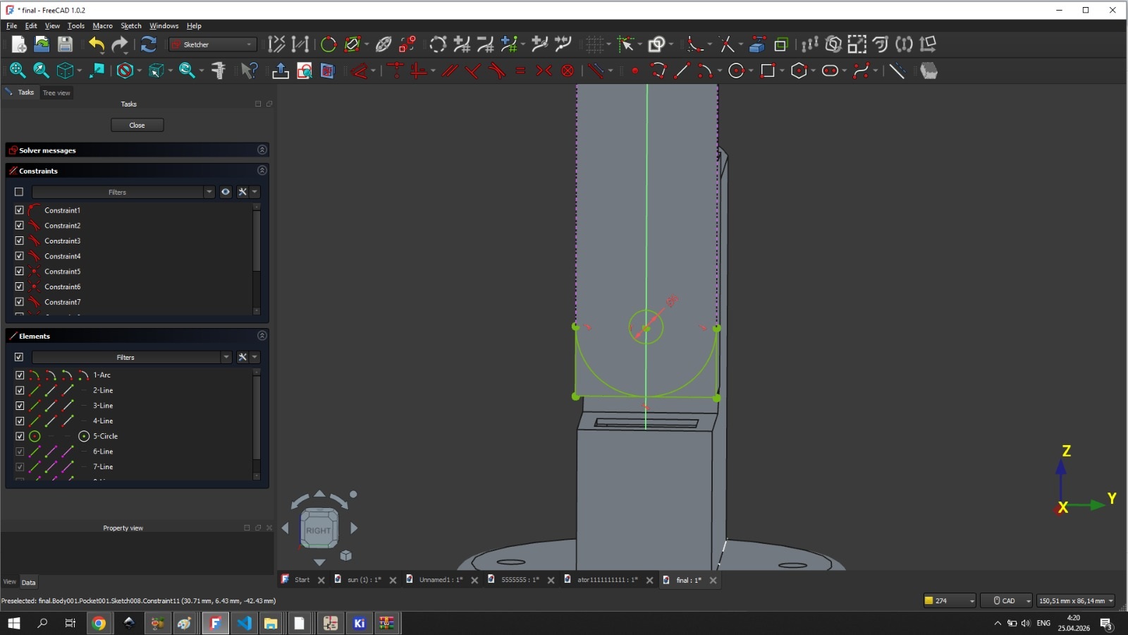
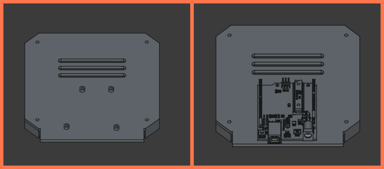
A rectangular tube extends downward from the sensor head to route the wires. The lower end of this tube — where it connects to the servo shaft — was made semicircular (radius 13 mm) to avoid interfering with the rotating mechanism. At the center of that semicircle, a double-sided hole with a 3 mm radius was created for the servo horn attachment.
The assembled upper section with all parts joined:
Lower Section — Ani
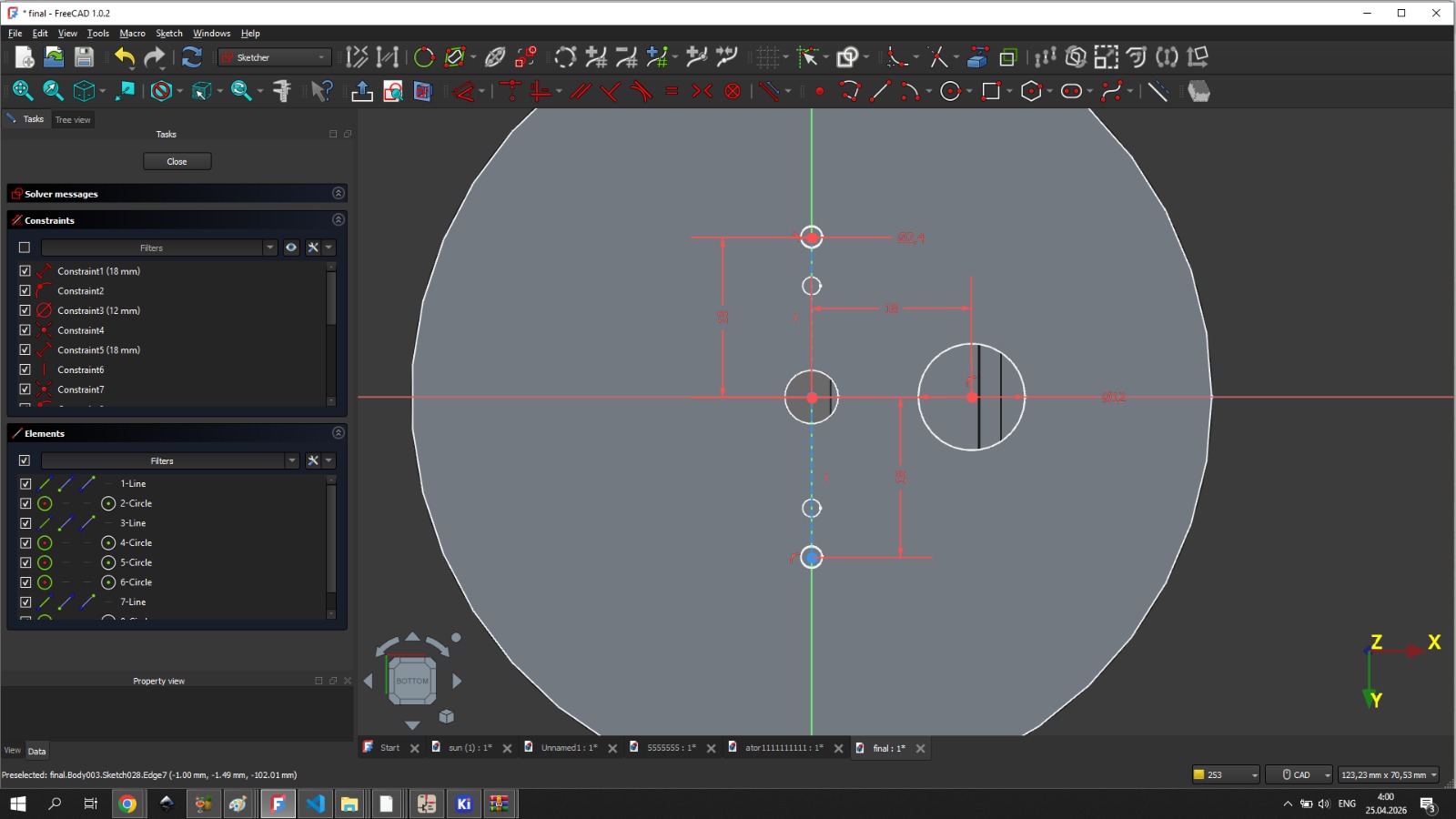
The lower enclosure had to fit the Arduino Uno and the horizontal servo motor side by side, with correct spacing and mounting positions, while also aligning precisely with Gevorg’s upper section through the circular connecting piece.
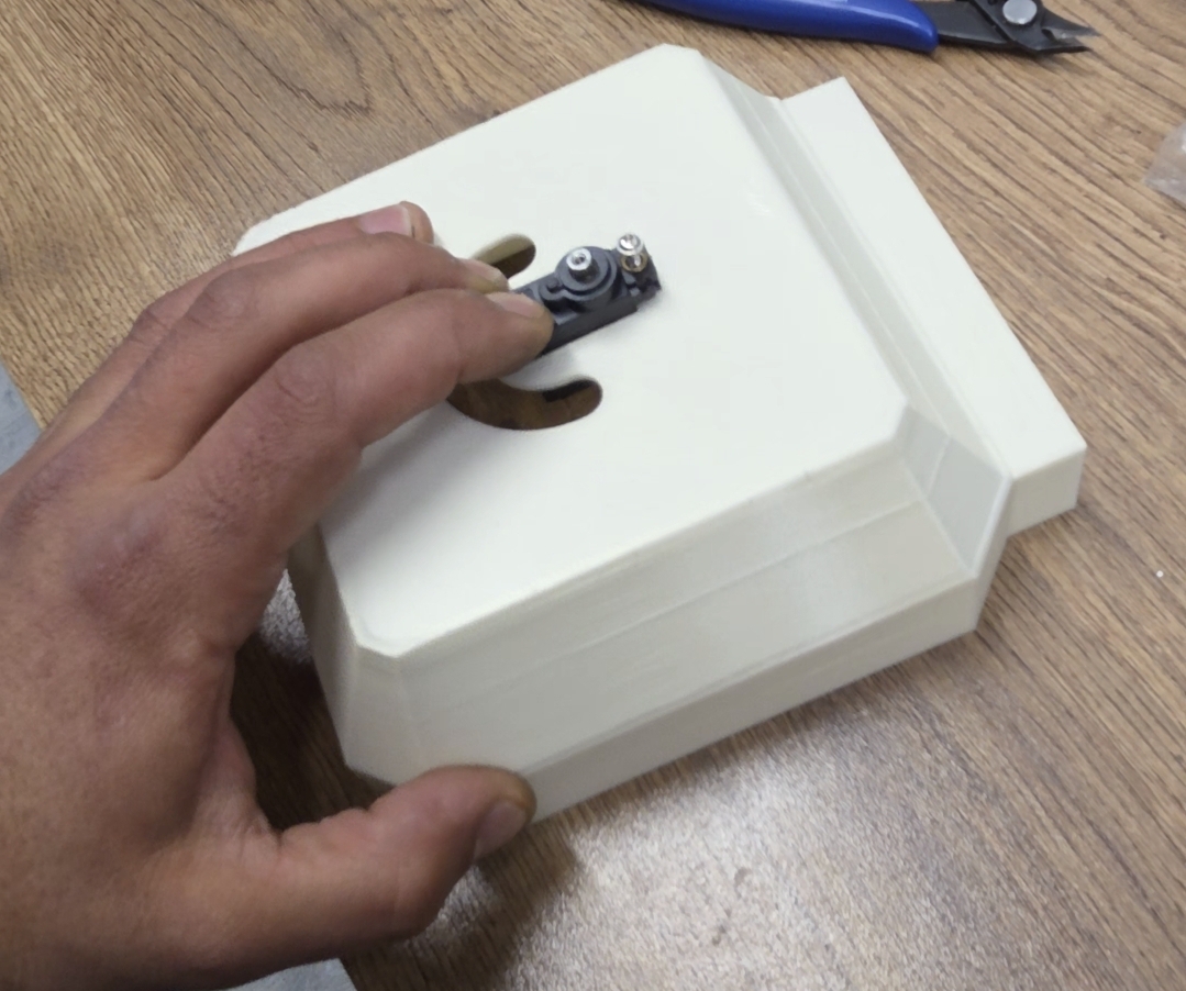
The enclosure lid was designed with four small support feet to keep it slightly elevated from the surface, allowing air circulation underneath. Ventilation holes were added to the lid to cool the Arduino Uno during operation.
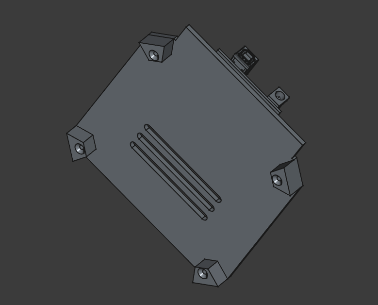
Mounting holes for the Arduino Uno were placed to match the board’s own mounting positions, so it could be secured with screws without any modifications to the board itself.
The circular connecting piece — which joins the upper and lower sections — was the most critical single component: its dimensions and hole placement had to match both halves simultaneously, since any error there would propagate through the entire assembly.
The full lower enclosure with the lid closed:
3D Printing
All parts were sliced in Orca Slicer and printed in Generic PETG Vanilla White. PETG was chosen for its strength, good layer adhesion, and heat resistance — important for a device that may operate outdoors in direct sunlight.
For parts with overhanging geometry, Tree Support was used rather than standard supports: it uses less material, is faster to generate, and leaves cleaner surfaces after removal.
Gevorg’s upper section parts were oriented to minimize the number of supports needed. The main body of the arm was printed vertically.
Ani’s lower enclosure parts required more careful orientation. The main body was placed with the inner face down against the build plate to maximize adhesion and reduce the number of unsupported areas. The lid was placed inner-side down for the same reason. The circular connecting piece required no supports because of its geometry.
Infill was set to 90% for the upper section parts to maximize structural rigidity, since those parts carry the load of the sensor PCB and wires and rotate with the servo.
Assembly
With all parts printed, we moved on to putting the system together.
Top Section Assembly
On the upper section, the four photoresistors were soldered onto the PCB only after it was already mounted in place — this way each sensor lined up exactly with its corresponding divider wall instead of being positioned by guesswork beforehand.
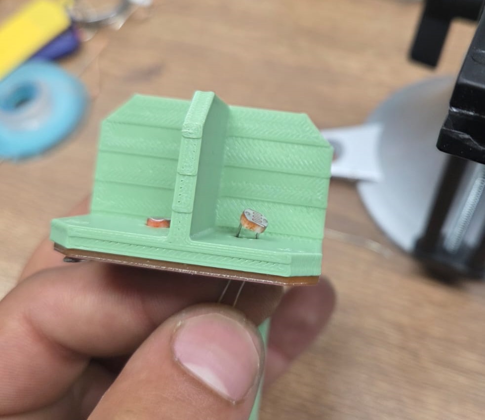
After soldering, the excess wire leads were trimmed off.
After that, the part that holds the vertical servo motor was screwed in. This had to be done at this stage — it would not have been accessible later.
The vertical servo motor was then attached to its dedicated part, which was designed to hold both the motor and its wires inside.
There was also a channel designed so that the wires coming out of the vertical arm could be routed inside, keeping everything neat. After connecting the wires, the two upper parts were joined together.
Bottom Section Assembly
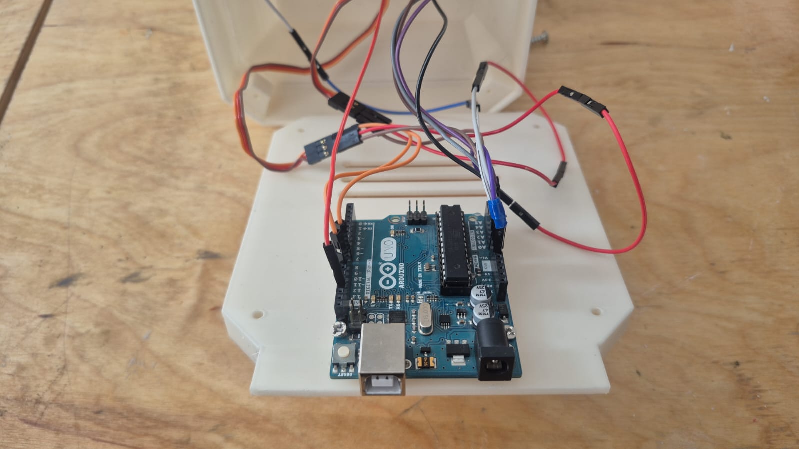
The servo motor responsible for horizontal-axis rotation was mounted inside the lower enclosure together with the Arduino Uno.
The Arduino Uno was secured with screws using the mounting holes designed during the modeling phase, and the wiring was routed through the dedicated openings in the enclosure walls.
Joining the Two Sections
With both sections complete, it was time to join them together. The connecting piece had dedicated screw holes for secure fastening and a channel for routing the wires from the upper section down into the lower enclosure.
Coding
After assembly, we moved on to programming.
Naming the Photoresistor Pins
To work with the data, we needed to name the 4 photoresistors. We moved our device to the position where both servo motors are at 0 degrees — 0° for the horizontal and 0° for the vertical — and began naming the pins according to the photoresistors:
#define topLeft  A1
#define topRight A0
#define bottomLeft A3
#define bottomRight A2
Reading Sensor Data
Next, we needed to read data from the photoresistors. We created variables with short pin names, assigned the sensor readings to the corresponding variables, and printed them to the Serial Monitor:
#define topLeft  A1
#define topRight A0
#define bottomLeft A3
#define bottomRight A2

void setup() {
  Serial.begin(9600);
  pinMode(topLeft, INPUT);
  pinMode(topRight, INPUT);
  pinMode(bottomLeft, INPUT);
  pinMode(bottomRight, INPUT);
}

void loop() {
  int tL = analogRead(topLeft);
  int tR = analogRead(topRight);
  int bL = analogRead(bottomLeft);
  int bR = analogRead(bottomRight);

  Serial.print("tL:");
  Serial.println(tL);

  Serial.print("tR:");
  Serial.println(tR);

  Serial.print("bL:");
  Serial.println(bL);

  Serial.print("bR:");
  Serial.println(bR);
  delay(1000);
}
We also added delay(1000); so that sensor values are read once per second.
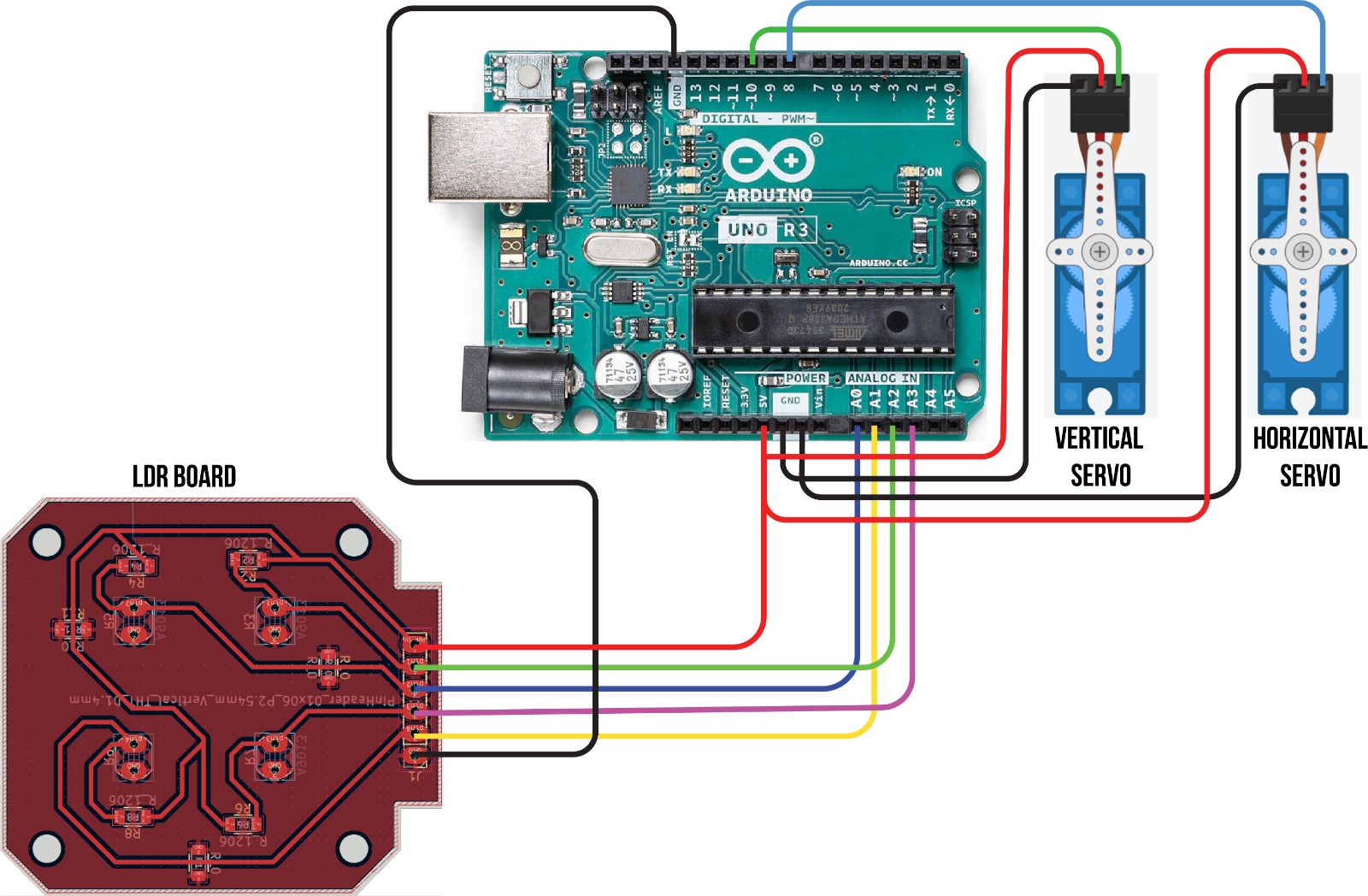
We connected the sensor PCB to the Arduino UNO: the four analog signal pins to A0–A3, and the power header to 5V and GND.
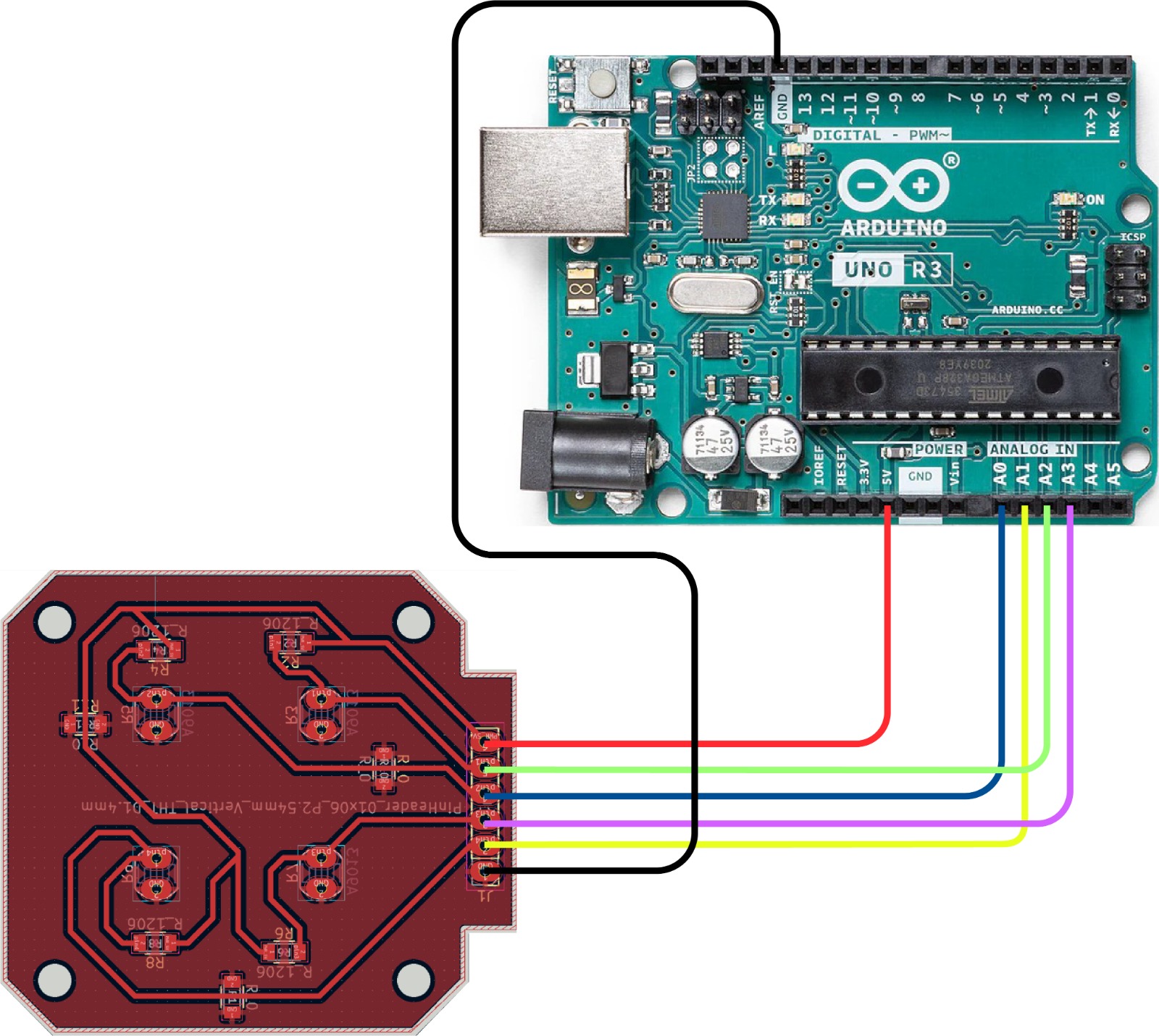
We then uploaded the code and opened the Serial Monitor to check whether each photoresistor was responding. To confirm the pin assignment was correct, we covered each sensor one by one with a finger and watched which value dropped in the output.
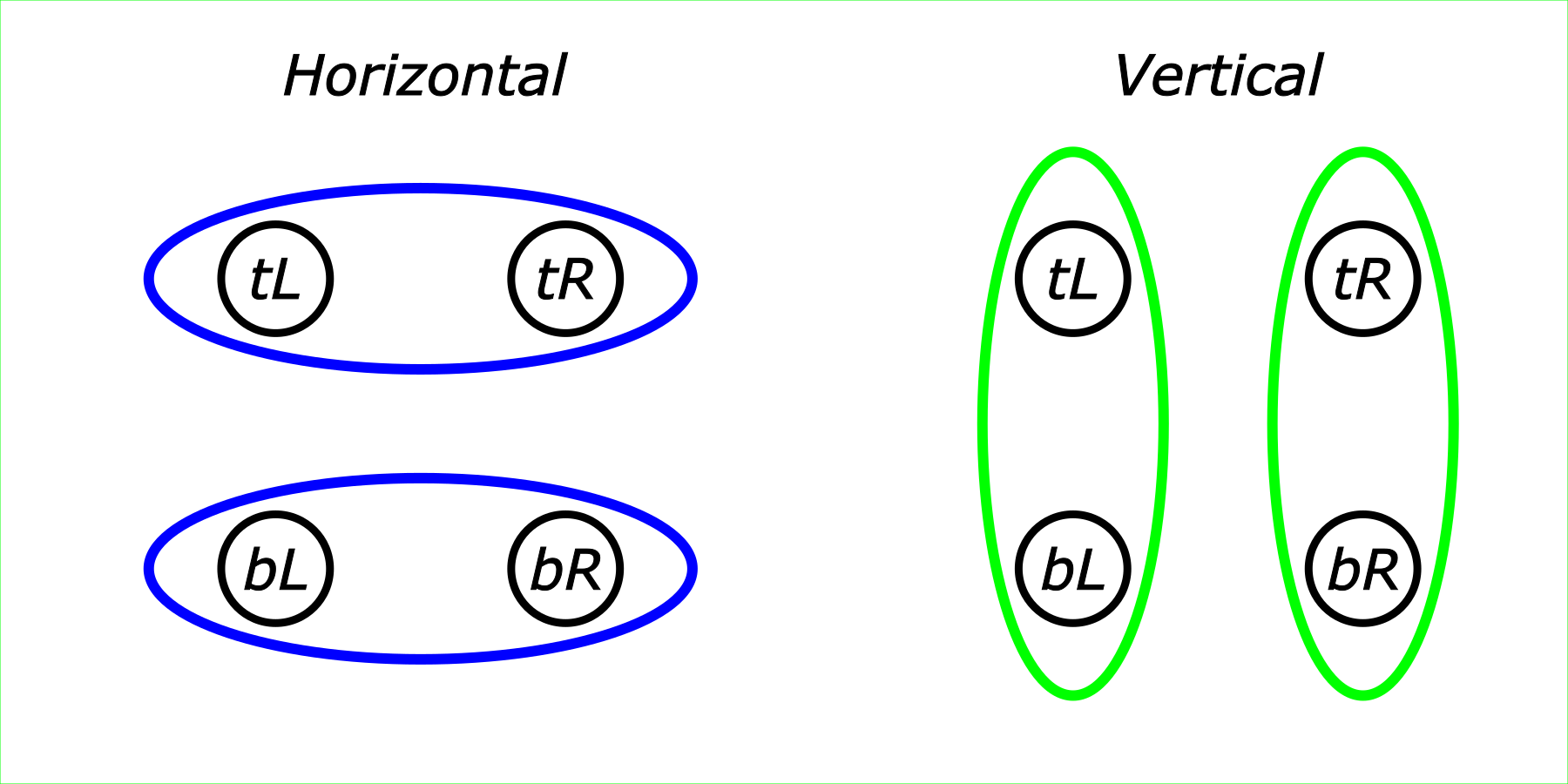
Mapping Sensor Pairs to Servo Axes
The next step was to determine which pairs of photoresistors control the horizontal servo motor, and which control the vertical servo motor. The layout is as follows:
Horizontal Servo Control
First, we developed code for the horizontal servo motor only.
We imported the Servo library:
#include <Servo.h>
Then created a servo object:
Servo horizontalservo;
And a global variable to track its position:
int horizontalpos = 90;
We initialized the variable with a value because the servo model we are using has no way of reporting its current position. For our task, we need to know the starting position of the servo — more on this shortly.
In the setup() function, we attached the servo to pin 8 and moved it to the initial position horizontalpos:
horizontalservo.attach(8);
horizontalservo.write(horizontalpos);
We chose tL and tR as the comparison pair.
Since a photoresistor works such that lower resistance corresponds to a lower analog reading, if tL < tR — meaning the Top Left sensor receives more light (and is oriented toward the 0° end of the servo’s range), while the Top Right sensor is oriented toward 180° — then we need to decrease horizontalpos by 1 degree.
Only 1 degree at a time, since after each movement we need to re-check whether the condition tL < tR still holds.
In code:
if(tL < tR) {
   horizontalpos = horizontalpos - 1;
   horizontalservo.write(horizontalpos);
   delay(100);
 }
And the opposite condition:
if(tR < tL) {
   horizontalpos = horizontalpos + 1;
   horizontalservo.write(horizontalpos);
   delay(100);
 }
With the sensor PCB already wired to the analog pins, we added the horizontal servo motor — signal wire to pin 8. This gave us the first complete circuit: four sensors reading light intensity, and one motor responding to it.
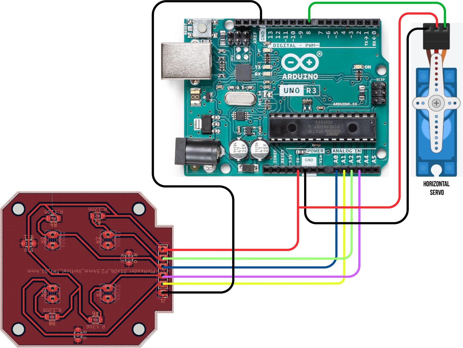
We tested the horizontal tracking indoors using a flashlight, moving it from side to side to confirm the servo followed the light source.
Adding Boundary Limits
The code had one issue: servo position is bounded between [0, 180], but our code placed no limits on the value. So for the first condition, we added a check that horizontalpos > 0 — meaning the motor will only move further if its current position is above 0. If it has already reached 0, it stays there even if the light intensity on the tL side is higher than on tR.
We added the same constraint for the opposite direction:
if(tL < tR && horizontalpos > 0) {
   horizontalpos = horizontalpos - 1;
   horizontalservo.write(horizontalpos);
   delay(100);
 }
if(tR < tL && horizontalpos < 180) {
   horizontalpos = horizontalpos + 1;
   horizontalservo.write(horizontalpos);
   delay(100);
 }
Preventing Oscillation with a Threshold
This fixed the boundary issue, but there was still another problem. If both sensor values are close to each other — say 112 and 116 — the code treats that as a meaningful difference and rotates 1 degree. After rotating, the values might become 111 and 109, which triggers a rotation back, and so on indefinitely. The device would keep oscillating and never settle.
To prevent this, we added a third condition: the motor only moves if the percentage difference between the two sensors exceeds a configurable threshold, stored in a global variable:
int threshold = 5;
This value can be adjusted to tune the sensitivity of the device.
With this added, the relevant code became:
if(tL < tR && horizontalpos > 0 && (tR - tL)*100/tR > threshold) { // Added percentage threshold condition
   horizontalpos = horizontalpos - 1;
   horizontalservo.write(horizontalpos);
   delay(100);
 }
if(tR < tL && horizontalpos < 180 && (tL - tR)*100/tL > threshold) { // Added percentage threshold condition
   horizontalpos = horizontalpos + 1;
   horizontalservo.write(horizontalpos);
   delay(100);
 }
The device now worked correctly.
Refactoring: A Universal Function for Both Axes
The next step was to add the same logic for the vertical servo motor.
We added the vertical servo motor to the circuit — signal wire to pin 10 — completing the full wiring for both axes.
With both servos connected, we refactored the control logic into a single universal function rather than duplicating it for each axis.
void sensdetect(int start, int finish, Servo &s, int &position ) {
  if(start < finish && position > 0 && (finish - start)*100/finish > threshold) {
    position = position - 1;
    s.write(position);
    delay(25);
  }
  if(finish < start && position < 180 && (start - finish)*100/start > threshold) {
    position = position + 1;
    s.write(position);
    delay(25);
  }
}
Where:
- start — the sensor value corresponding to the 0° end of the servo’s range
- finish — the sensor value corresponding to the 180° end
- s — the servo motor (horizontal or vertical)
- position — the current position of the corresponding servo
Final Code
With this single function handling both axes, the final code is as follows:
#include <Servo.h>

#define topLeft  A1
#define topRight A0
#define bottomLeft A3
#define bottomRight A2

int horizontalpos = 90;
int verticalpos = 90;
int threshold = 5;

Servo horizontalservo;
Servo verticalservo;

void setup() {
  Serial.begin(9600);
  pinMode(topLeft, INPUT);
  pinMode(topRight, INPUT);
  pinMode(bottomLeft, INPUT);
  pinMode(bottomRight, INPUT);
  horizontalservo.attach(8);
  verticalservo.attach(10);

  horizontalservo.write(horizontalpos);
  delay(500);

  verticalservo.write(verticalpos);
  delay(500);
}

void loop() {
  int tL = analogRead(topLeft);
  int tR = analogRead(topRight);
  int bL = analogRead(bottomLeft);
  int bR = analogRead(bottomRight);

  sensdetect(tL, tR, horizontalservo, horizontalpos);
  sensdetect(bL, tL, verticalservo, verticalpos);
}

void sensdetect(int start, int finish, Servo &s, int &position ) {
  if(start < finish && position > 0 && (finish - start)*100/finish > threshold) {
    position = position - 1;
    s.write(position);
    delay(25);
    Serial.print("position:");
    Serial.println(position);
  }
  if(finish < start && position < 180 && (start - finish)*100/start > threshold) {
    position = position + 1;
    s.write(position);
    delay(25);
    Serial.print("position:");
    Serial.println(position);
  }
}
Problems and Solutions
PCB Routing — Trace Crossings
When routing the four-channel sensor PCB in KiCad, several traces crossed each other on a single-layer board with no way to re-route them cleanly. We solved this by adding three 0 Ω resistors as jumpers — they act as physical bridges that let a trace cross over another without creating a short circuit.
Sensor Positioning — Soldering Order
The photoresistors had to be positioned exactly flush with the divider walls of the 3D-printed enclosure, with no room for adjustment after the fact. If we had soldered them before mounting the PCB, there was no reliable way to get the alignment right. The solution was to mount the PCB first, then insert the photoresistors through the holes from the opposite side and solder them in place — the enclosure itself acted as the positioning jig.
Coding — Pin Variables Not Used Consistently
During the first sensor test, the device was behaving unexpectedly — some sensors seemed to respond incorrectly, and changing the pin assignment in the #define block at the top of the code had no effect.
The problem turned out to be a consistency issue: the pin names were defined correctly at the top:
#define topLeft  A1
#define topRight A0
#define bottomLeft A3
#define bottomRight A2
But in the loop(), the analogRead() calls were using the raw pin numbers instead of these names:
int tL = analogRead(A1);  // should have been analogRead(topLeft)
int tR = analogRead(A0);
This meant changing topLeft from A1 to A0 had no effect on what was actually being read. Once we replaced all the hardcoded pin numbers with the #define names throughout the code, the sensor assignment became consistent and the problem disappeared.
Possible Improvements
The system is functional, but there is room for further development.
-
The code works, but requires additional logic. For example, if the device’s head is at position (0°, 0°) and the light is most intense from the left side, there is currently no logic to make it rotate all the way to the opposite position (179°, 180°). The device would simply stop at the boundary and remain there. Additionally, the current code compares sensors in only two pairs: top-left vs. top-right to drive the horizontal servo, and bottom-left vs. top-left to drive the vertical servo. For more accurate tracking, comparisons between other sensor pairs should also be incorporated.
-
It is also worth noting that our device locates the position of maximum light intensity, but it is not designed to actually rotate a solar panel. A real-world solar panel tracker would require a much more robust mechanical construction. Furthermore, for energy-efficient operation, the motor drive system should use worm gears. A worm gear prevents back-rotation when the motors are powered off — an important property for a tracker that needs to hold its position without continuously drawing power. A similar mechanism was used by our lab instructor Babken Chugaszyan in his final project.
-
Additionally, placing capacitors (100–470 µF) across the power supply of each servo motor would help stabilize voltage, reducing noise and preventing unexpected resets of the microcontroller caused by current spikes during motor movement.
Design Philosophy
No AI tools were used at any stage of this project — neither for the 3D design nor for the code. Every decision, from the resistor value calculation to the servo control algorithm, was worked out by the team from first principles.
The programming approach was deliberately incremental: we started with the simplest possible step (reading one sensor and printing its value), confirmed it worked, then added the next layer (servo movement), then the next (boundary limits), and finally the oscillation threshold. Each step was tested before the next one was added. This turned out to be the most effective way to debug the system — when something didn’t work, we knew exactly which layer had introduced the problem.
Files
- Sensor PCB — KiCad project
- Milling files — SVG
- 3D models — FreeCAD (Gevorg’s upper section)
- 3D models — FreeCAD (Ani’s lower section)
- All STL files — ZIP