4. Embedded Programming
Group assignment: demonstrate and compare the toolchains and development workflows for available embedded architectures
MCU Comparison
We checked the datasheets for the STM32-F3 Discovery board, the xiao rp2040 and the Atmega328p in order to compare them:
| Feature | RP2040 (Seeed Studio XIAO) | STM32F303VCT6 (Discovery) | Arduino Uno (ATmega328P) |
|---|---|---|---|
| CPU Architecture | Dual ARM Cortex-M0+ | Single ARM Cortex-M4 | Single AVR RISC |
| CPU Clock Speed | Up to 133 MHz | Up to 72 MHz | Up to 16 MHz |
| Register Size | 32-bit | 32-bit | 8-bit |
| Flash Memory | 2 MB (Onboard) | 256 KB | 32 KB |
| SRAM (RAM) | 264 KB | 48 KB | 2 KB |
| Operating/IO Voltage | 3.3V (Accepts 1.8V - 3.3V) | 3.3V (Board accepts 5V) | 5V (Chip accepts 2.7V - 5.5V) |
Tinker CAD with Arudino UNO
First of all, we started our assignment with simulatiion. We used tinker cad to simulate Arduino uno with neopixel strip.
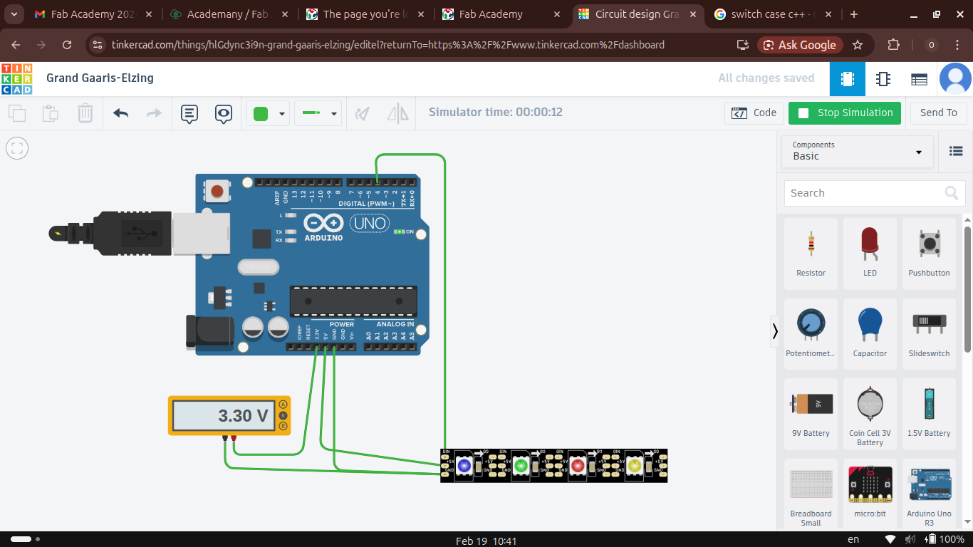
Below you can see the code that we used.
#include <Adafruit_NeoPixel.h>


#define PIN        4 // Data pin for the NeoPixels
#define NUMPIXELS  4 // Number of NeoPixels

// Initialize the NeoPixel library
Adafruit_NeoPixel strip(NUMPIXELS, PIN, NEO_GRB + NEO_KHZ800);

void setup() {
  strip.begin();           // Initialize pins for NeoPixel
  strip.show();            // Turn all pixels off
  strip.setBrightness(50); // Set brightness (0-255)
}

void loop() {
  // Set all 4 pixels to White (Red, Green, Blue)
  for(int i=0; i<NUMPIXELS; i++) {
    switch(i)
    {
        case 0:
            strip.setPixelColor(i, strip.Color(0, 0, 255));
            break;
        case 1:
            strip.setPixelColor(i, strip.Color(0, 255, 0));
            break;
        case 2:
            strip.setPixelColor(i, strip.Color(255, 0, 0));
            break;
        case 3:
            strip.setPixelColor(i, strip.Color(255, 255, 0));
            break;
    }
  }
  strip.show(); // Update strip with new color
  delay(100);
}
In this example we learned basic code components. void setup(). Function which runs one time in start up and we use it setup our microcontroller. Than we have void loop() which is infinite loop and we write our main code here. Than we learned about for loop which we use to set color for each led. Finally, we used switch case to set different colors for each led.
RP2040
Than we took Seeed studio’s XIAO RP2040 to program it using Arduino IDE
First we need to install it from arduino website.
After installation we need to download library for RP2040. We need to go to board manager and download this board library.
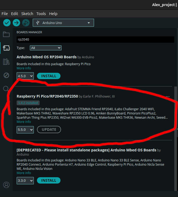
Than we wrote a simple program to toggle onboard neopixel led.
Here is code
#include <Adafruit_NeoPixel.h>

#define PIN_RGB        12  // The WS2812 LED is connected to Pin 12
#define PIN_POWER      11  // The power enable pin for the RGB LED
#define NUMPIXELS      1   // The board has 1 onboard RGB LED

Adafruit_NeoPixel pixels(NUMPIXELS, PIN_RGB, NEO_GRB + NEO_KHZ800);

void setup() {
  pinMode(PIN_POWER, OUTPUT);
  digitalWrite(PIN_POWER, HIGH); // Turn on the power to the RGB LED
  pixels.begin();
}

void loop() {
  pixels.clear();

  // Set color to Red
  pixels.setPixelColor(0, pixels.Color(255, 0, 0));
  pixels.show();
  delay(500);

  // Set color to Green
  pixels.setPixelColor(0, pixels.Color(0, 255, 0));
  pixels.show();
  delay(500);

  // Set color to Blue
  pixels.setPixelColor(0, pixels.Color(0, 0, 255));
  pixels.show();
  delay(500);
}
STM32F3DISCOVERY BOARD
We also explored STM32F3DISCOVERY board. We used STM32CubeMX program to generate setup code and hardware application level library to use during programing. And than we setted up vscode to program board.
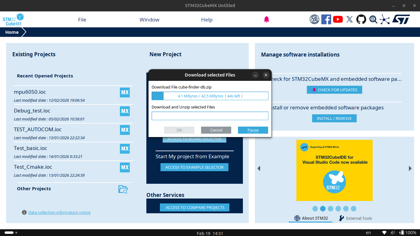
STM32CubeMX
First of all you need to install STM32CubeMX program from this website.
Than you need to open it
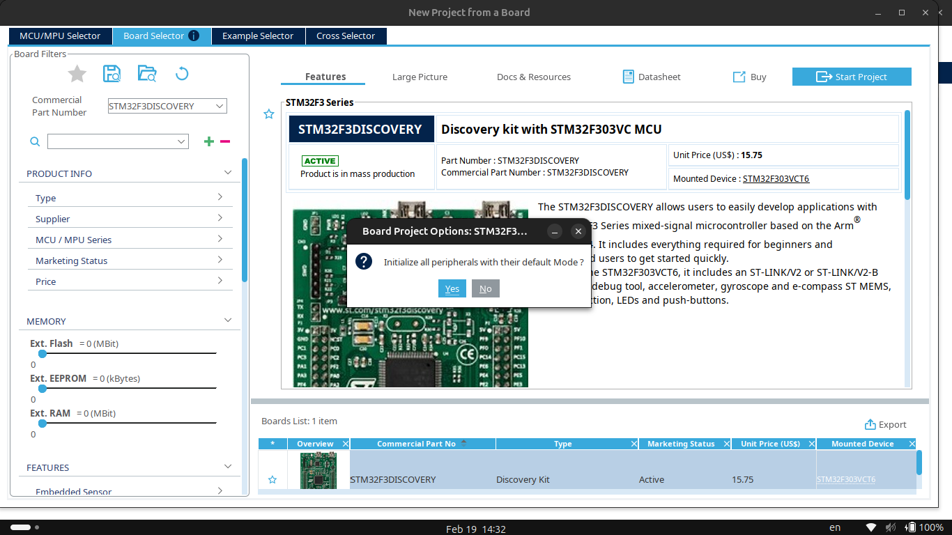
- Choose your board from board selector.
- Initilaize it with default settings
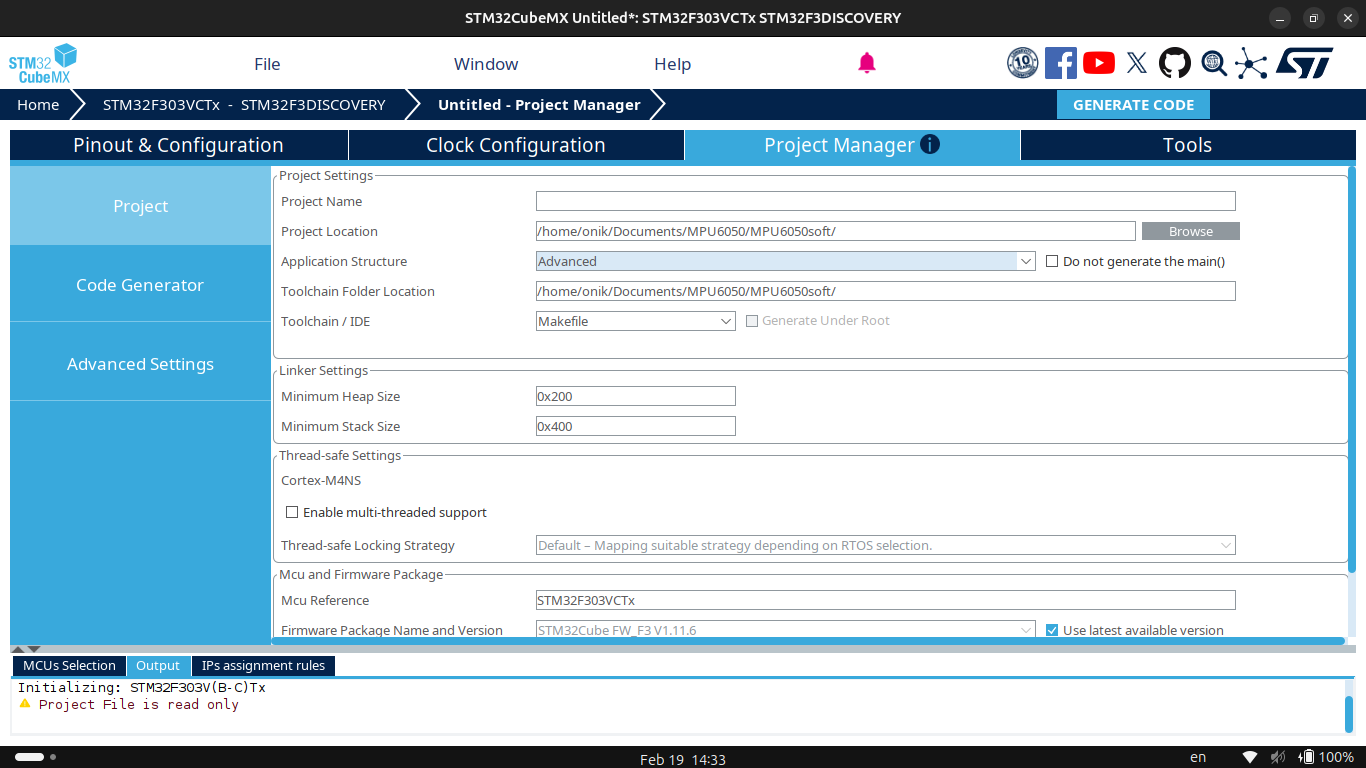
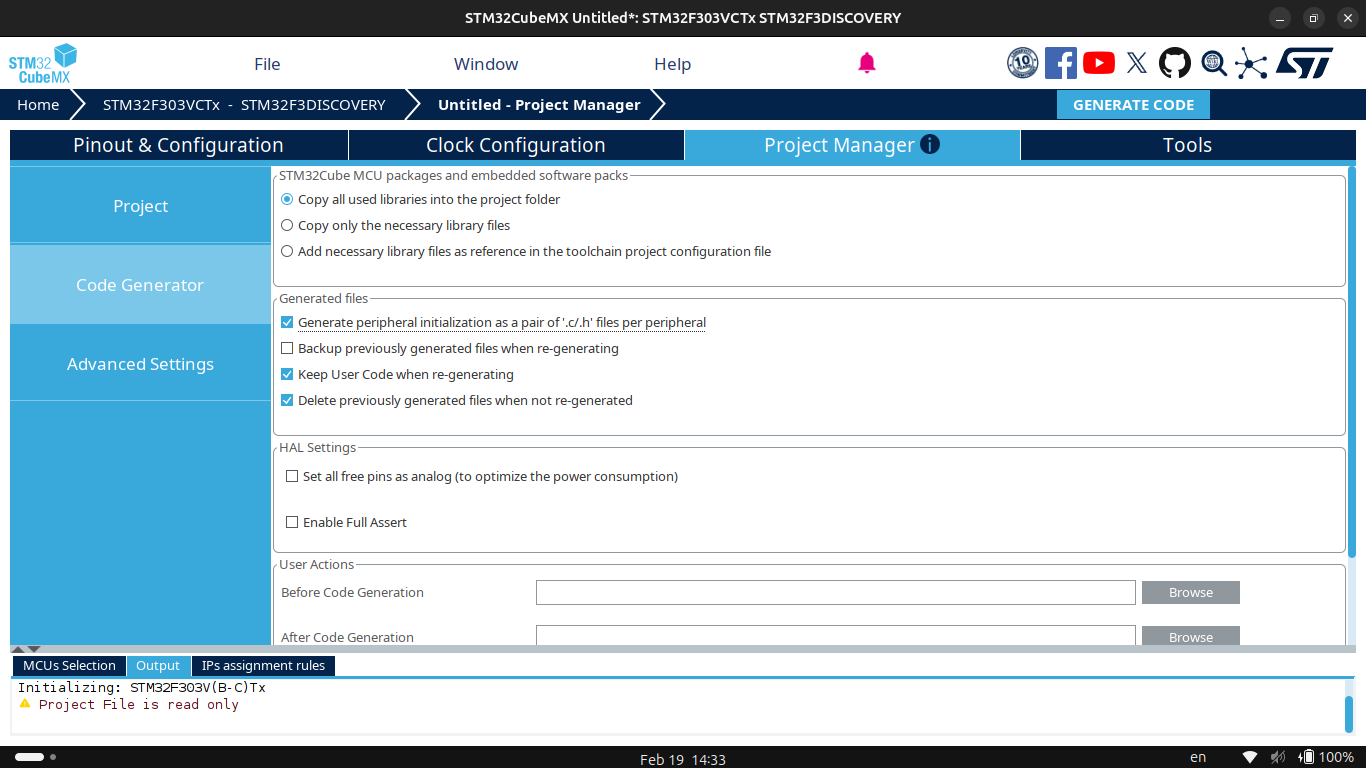
- In project manager tab choose your project directory and choose Cmake project
- Finally Generate code.
 |
 |
 |
 |
Setting up Vscode
To setup Vscode we need to install compiller and make program to build our program.
here is what we need
sudo apt update
sudo apt install -y \
  gcc-arm-none-eabi \
  openocd \
  make \
  cmake \
  ninja-build \
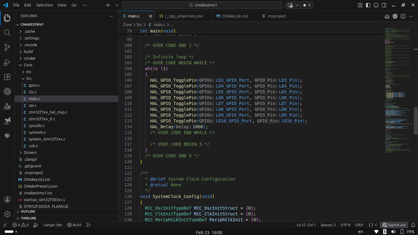
Than open your Vscode and search for an extension called STM32Cubeide pack and install it. Reload your VScode and open the folder of generated project. The Extension that you have just installed will configure settings for you. Than you can write your code in main.c and flash it by pressing run button in your vscode.
Here is how it should look like. Also you will need to install cortex-debug extension to have a real time debug option.
And Below is the video for discovery board blinking leds.
Arduino UNO & I2C LCD
For the group assignment, we used an I2C LCD display, Arduino UNO, and jumper wires. The goal was to install the Arduino IDE, understand the workflow, and print text on the LCD screen.
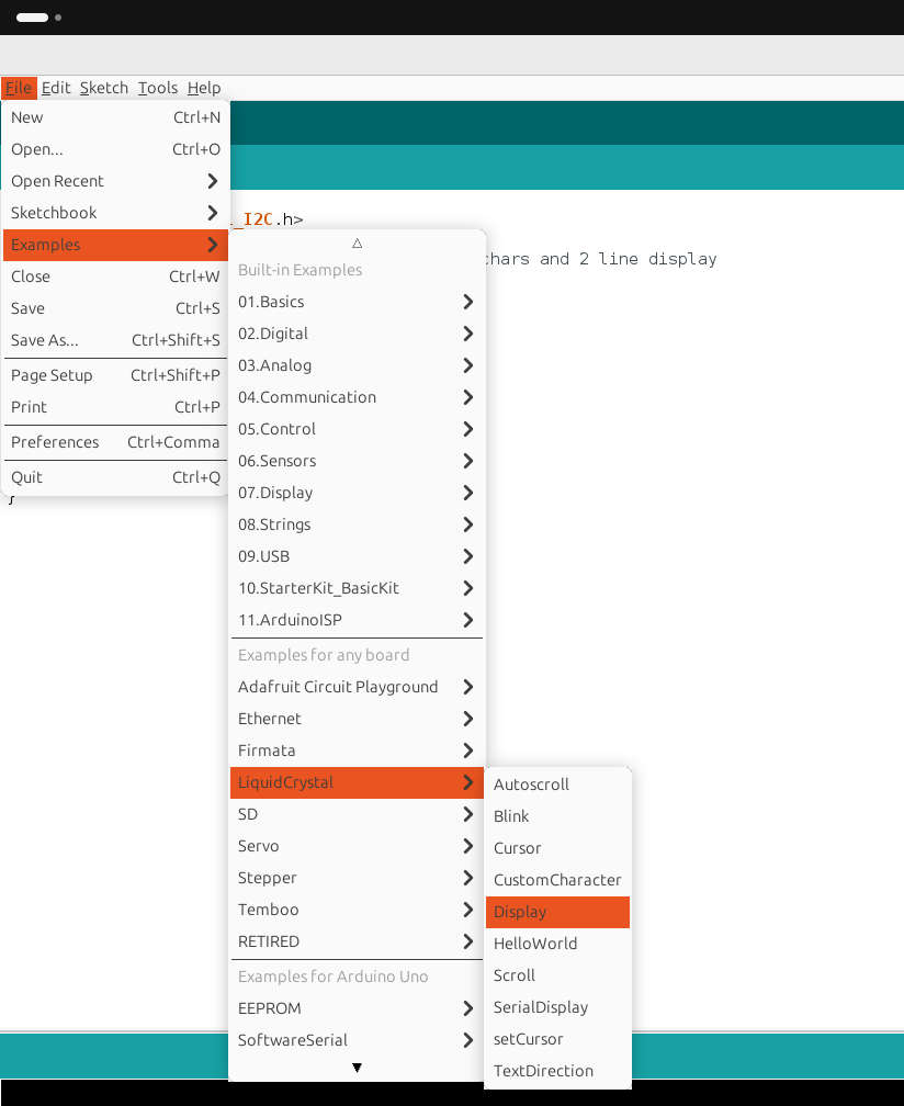
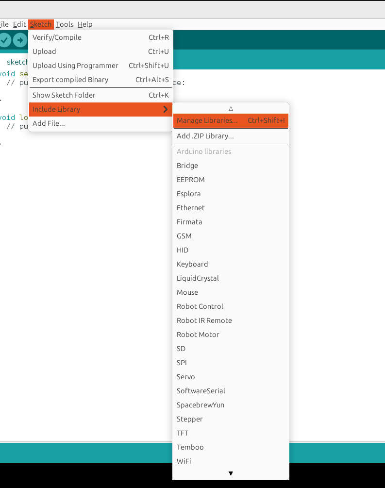
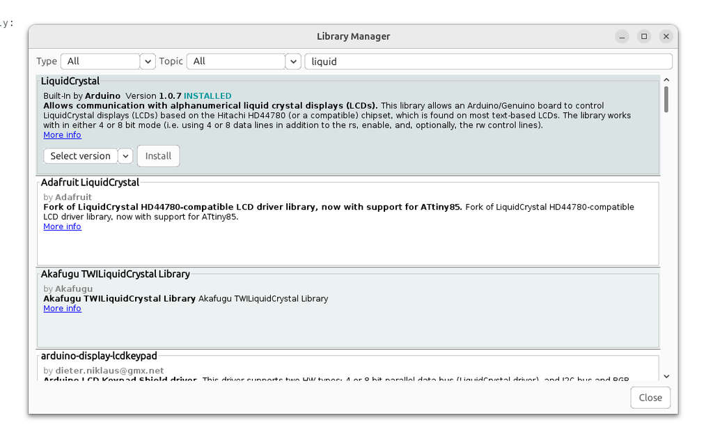
To begin, I followed the official Arduino documentation. While reading it, I quickly realized that it was necessary to install the LiquidCrystal library in the Arduino IDE. To install it, I navigated to Sketch → Include Library → Manage Libraries, searched for LiquidCrystal, and installed it.
After preparing the programming environment, the next step was to connect the LCD to the Arduino UNO and then connect the Arduino to the computer. When connecting the Arduino to the computer, several additional configurations were required to select the correct port and establish communication.
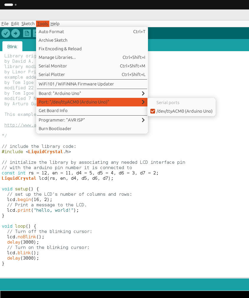
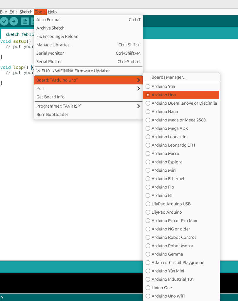
More details can be found at the Group Assignments link. Below is the result I obtained.
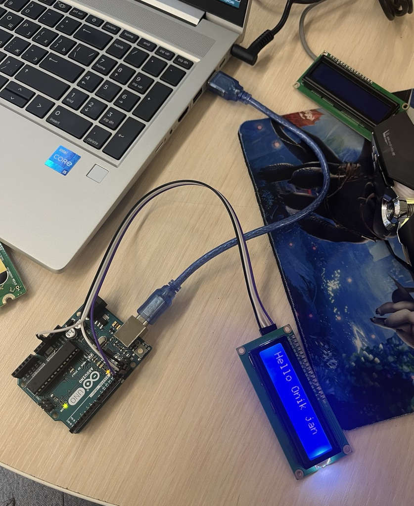
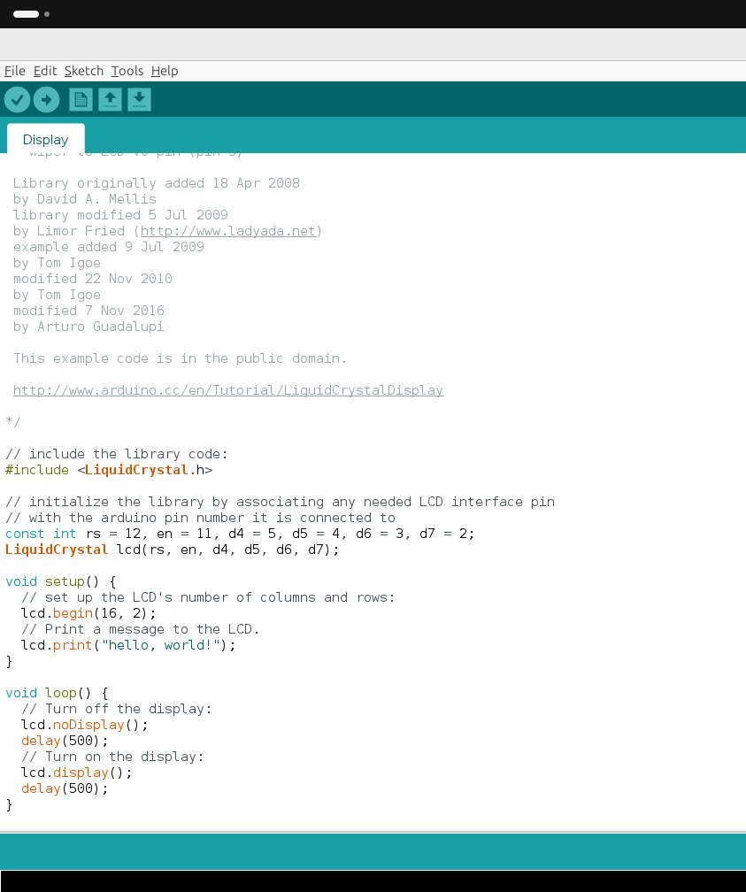
After completing all these steps, I realized that I could have simply used the ready-made example codes available for printing text on the LCD 😅