10. Output Devices
Group assignment:
- Measure the power consumption of an output device.
Gyumri lab
Overview
For this group assignment, we needed to measure the power consumption of an output device.
To understand why this matters and where it applies in practice, we decided to look at a real example — the final project of Ani Petrosyan, which requires the use of LED strips.
Context: Ani’s Project
Since LED strips operate on 12V DC, Ani’s board is powered from a 12V DC supply. The board includes a voltage regulator that steps 12V DC down to 5V DC to power the microcontroller and sensors.
The 12V LED strips are controlled via MOSFET transistors (50N03, TO-252 package). According to the KIA 50N03 datasheet, the absolute maximum continuous drain current is 50A — but this assumes ideal thermal conditions with a heatsink.
In Ani’s project, no heatsink is used. The KIA 50N03 datasheet specifies a junction-to-ambient thermal resistance (RθJA) of 50°C/W and a maximum power dissipation of 60W at 25°C. Without a heatsink, heat dissipation is significantly limited by the TO-252 package alone. Based on these thermal constraints, we adopt a conservative practical limit of 5A for safe continuous operation without a heatsink.
Setup & Initial Measurement
In our lab, we had an LED strip with 5 sections, each section measuring 25 mm in length.
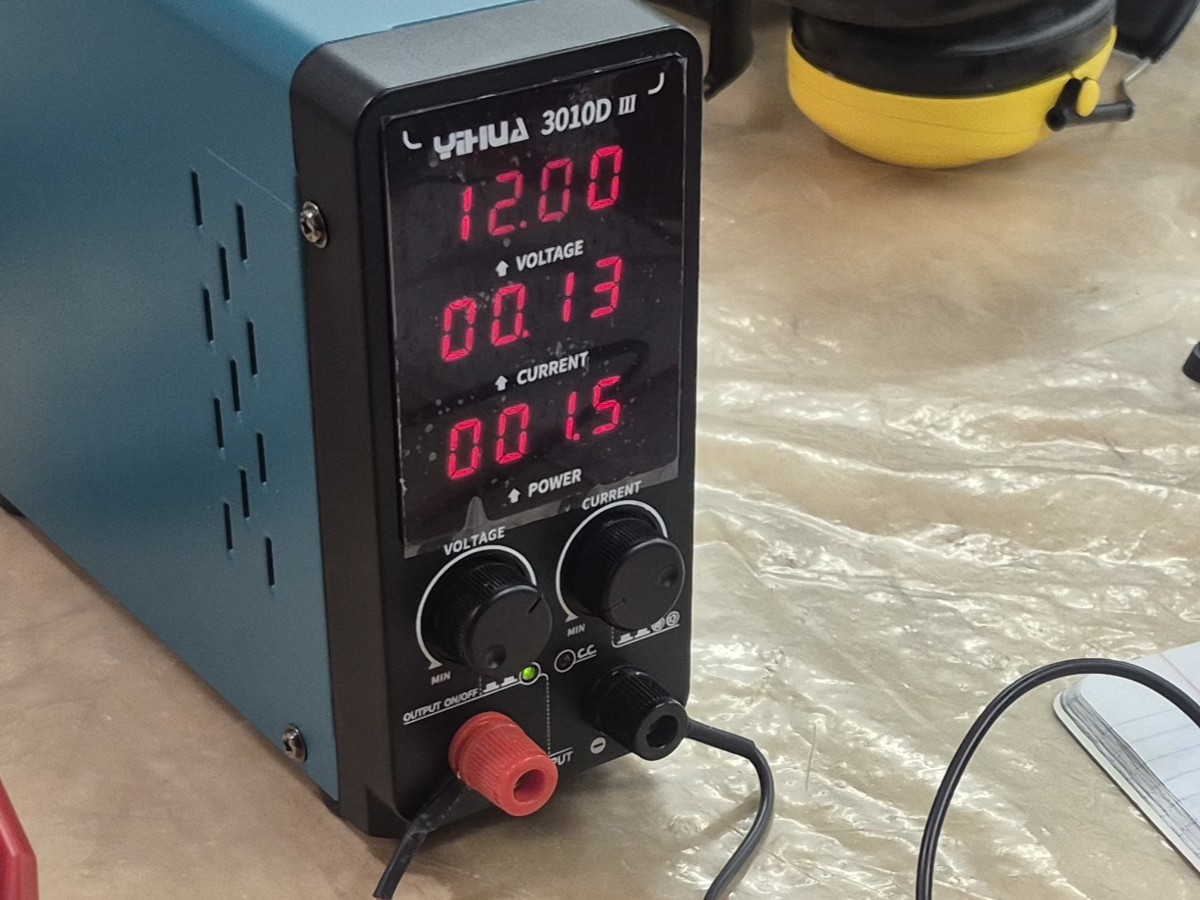
We started by powering the strip from the lab’s bench power supply (YIHUA 3010D III), setting the output to:
- Voltage: 12V
- Current limit: 1A After turning it on, the power supply displayed a current draw of approximately 0.13A.
However, the power supply readout has limited precision, so we used a multimeter for a more accurate measurement.
Measuring with a Multimeter
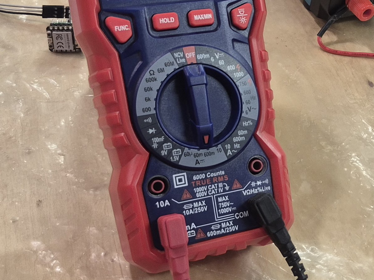
When using a multimeter, probe connections differ depending on what is being measured:
- Voltage or resistance: probes are connected in parallel across the contacts.
- Current: probes are connected in series, breaking the circuit.
- The black probe (negative) always goes into the COM port; the red probe goes into the port that matches the measurement type. Since we were measuring current, the red probe was connected to the 600mA input port.
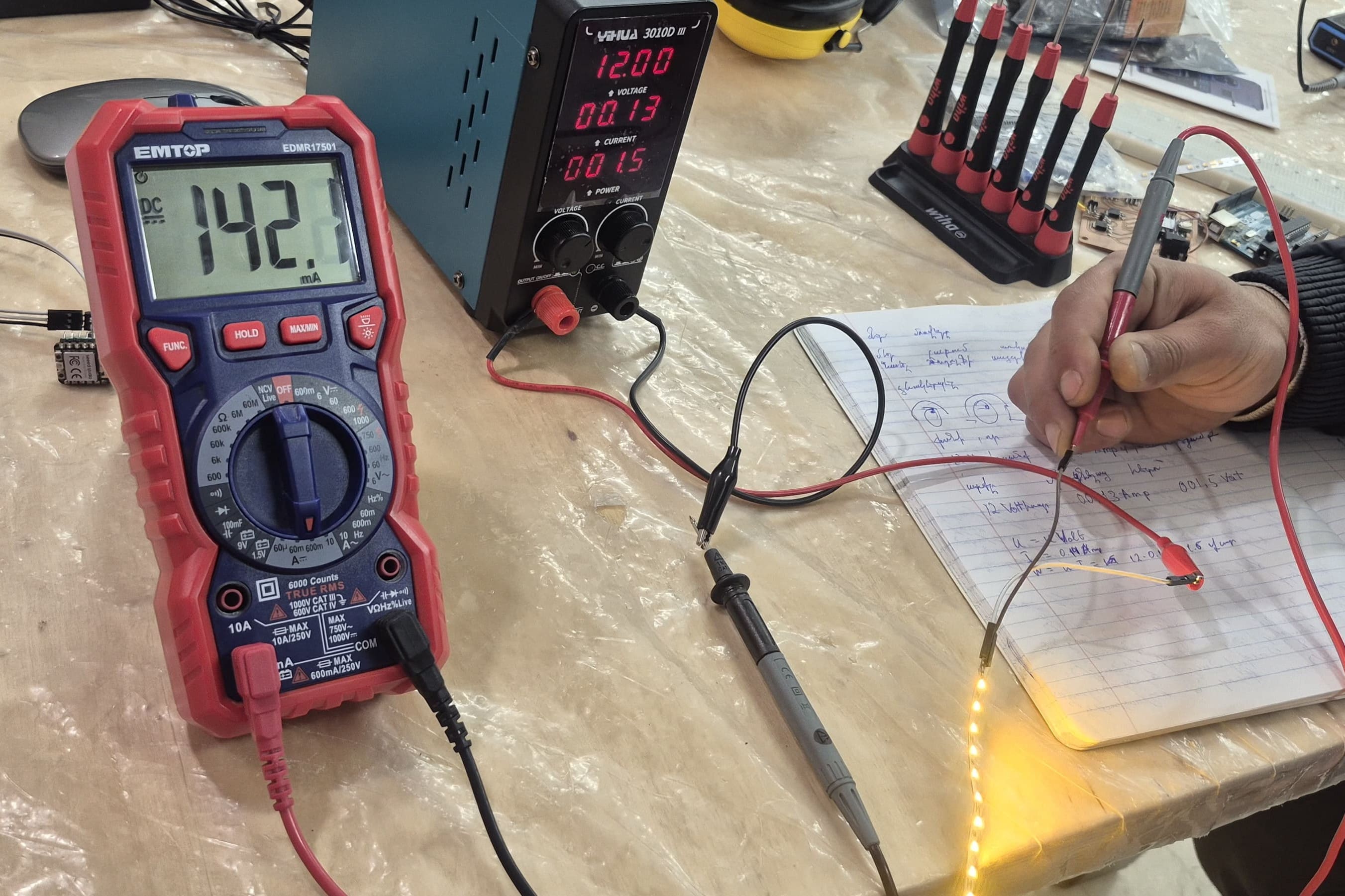
The multimeter gave us the following result:
Calculations
Power Consumption
Current alone only tells us how much charge is flowing — to know how much electrical energy the strip actually uses, we need power, calculated as:
With the strip powered at 12V and drawing 142.1 mA (0.1421 A):
So the full 5-section strip consumes approximately 1.7 W.
Current and Power per LED Strip Section
To find the current and power draw of a single LED section, we divided the total measured values by the number of sections:
Safety Derating for the MOSFET
To ensure reliable operation, we applied a standard 30% safety derating to the practical maximum current. This accounts for real-world factors such as ambient temperature, PCB heating, and component tolerances — it is common practice to never run a component at its rated limit.
Given the practical limit of 5A = 5000 mA without a heatsink:
Maximum Number of Sections
With 28.42 mA per section and a 3500 mA safe limit:
Maximum LED Strip Length
Since each section is 25 mm long:
At 0.341 W per section, this maximum length of 123 sections would draw approximately 42 W in total at 12V — well within what a standard 12V bench or wall supply can provide.
Conclusion
Based on the measurements and thermal constraints of the 50N03 MOSFET without a heatsink, Ani can safely use up to 3.08 meters of this LED strip in her final project, drawing approximately 42 W at full length. This ensures stable and reliable operation within the designed circuit constraints.
Dilijan Lab
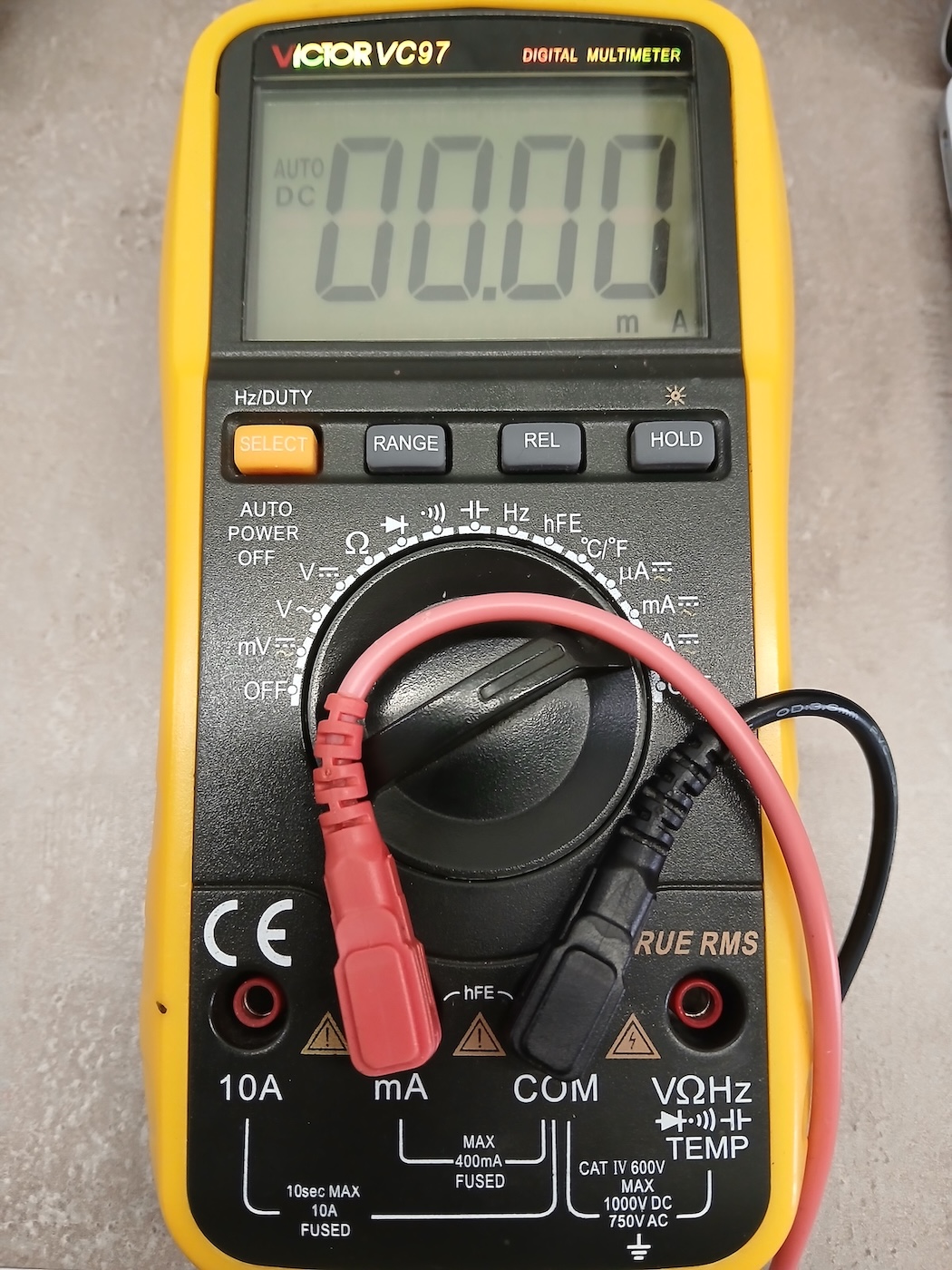
The first thing we had to do was to change the location of the red probe on our multimeter. We measured current using the mA/µA measurement modes instead of the V/Ω input, because these modes use different internal circuits and protection mechanisms inside the multimeter. If we would require higher current intensity (higher than 400mA), we would have to plug the red probe in the hole on the left.
To measure current correctly, the multimeter must be connected in series with the circuit so that it acts as a bridge for the current flow, whereas voltage and resistance are measured across the component.
Testing DC Motor
A DC motor is an electrical machine that converts direct current (DC) electrical energy into mechanical energy, usually using magnetic fields and a rotating coil (rotor) inside a fixed magnetic field (stator).
To understand how much current the DC motor consumes, we did the following setup:
- One wire of the motor was connected to the GND of the DC Power Supply
- The other wire was connected to the GND of the multimeter
- Then we applied 9V from the DC Power Supply through the multimeter.
From the measurement, we observed that the motor consumes around 180 mA at 9V. Converting this to power:
So the DC motor draws approximately 1.62 W under this test condition.
This kind of check matters more than it might seem — later that same week, Mariam ran into exactly this problem on her own robot-car PCB: after getting both motors finally running, the board overheated and burned out within seconds, traced back to power and stabilization issues she hadn’t accounted for when sizing the regulator and capacitors for the motors’ current draw.
This was a really good practical example of how theory directly affects real hardware 😄
Testing LCD
We had already tested the LCD a few weeks ago using an example circuit built by Hrach.
To repeat the test, we assembled the same setup using a DC Power Supply, multimeter, and the LCD.
The connections were done as follows:
- The + of the DC Power Supply was connected to the + of the multimeter
- The GND of the multimeter was connected to the GND of the LCD
- The 5V pin of the LCD was connected to the GND of the Power Supply, forming a closed-loop circuit for measurement
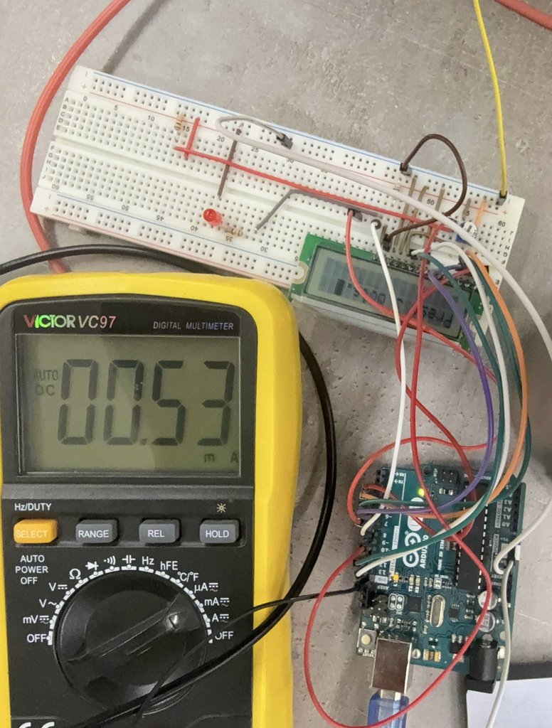
From the measurement, we observed that the LCD consumes around 0.53 mA at 5V. Converting this to power:
So the LCD draws approximately 2.65 mW — a very small load compared to the motor or the LED strip.
Testing FAN
To measure the current consumption of the fan, we powered it from the DC Power Supply set to 12V, using the same series connection setup:
- The “+” of the multimeter was connected to the “+” of the DC Power Supply
- The “-” of the DC Power Supply was connected to the “-” of the FAN
- The “-” of the multimeter was connected to the “-” of the DC Power Supply
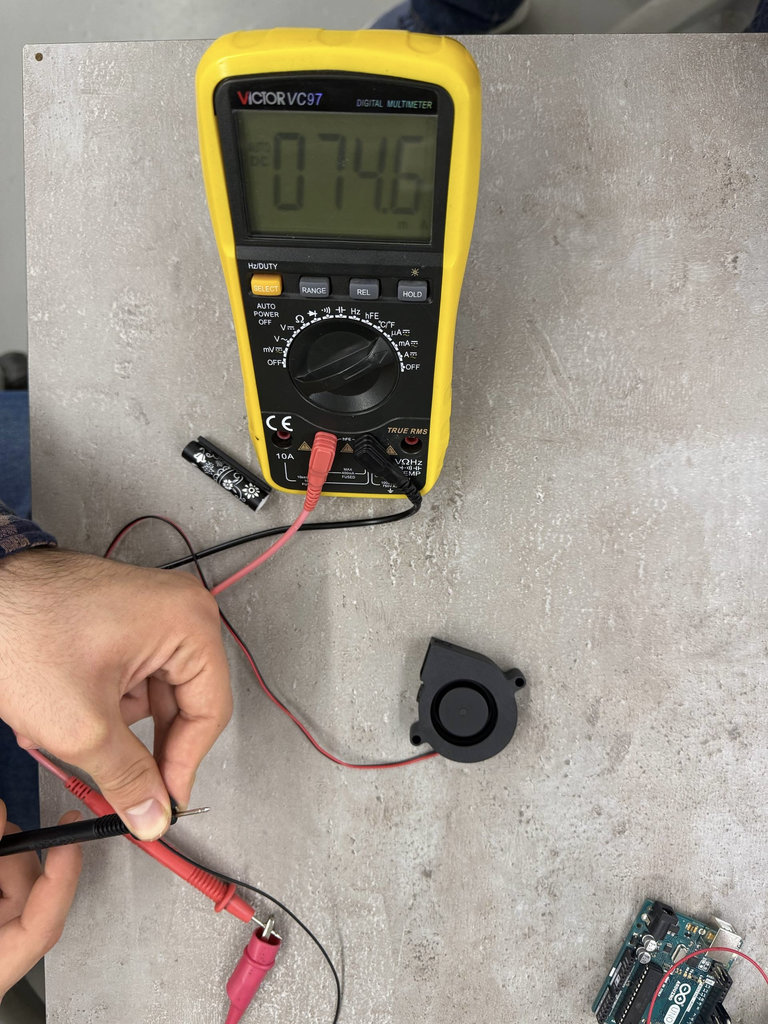
From the measurement, we observed that the fan consumes around 74.6 mA at 12V. Converting this to power:
So the fan draws approximately 0.9 W.