
Week 10
AI prompt:
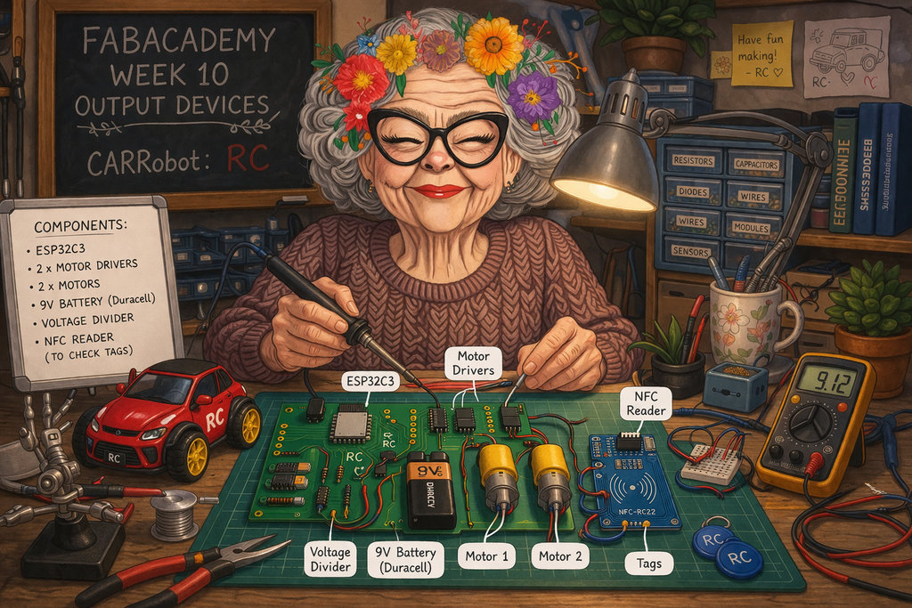
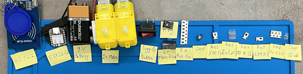
“Now need to create an image for week 10 'Output Devices'. This week, she again designed a PCB for her CARRobot. This time she used these components: . ESP32C3 - for WiFi communication with Joystick . 2 Motors and 2 Motor Drivers . 9 Volt Battery (Duracell) . Voltage divider to read the voltage of the battery . NFC Reader(to check Tags)”
Output Devices
The full group assignment — testing the power supply of several output devices (DC motor, LCD, fan) with a multimeter and a DC power supply — is documented on our group assignment page. Below is my reflection on it.
Correction: in my first version of this reflection, I only reported the current each device drew (in mA) and called that the "power consumption." That was wrong — current alone isn't power. My instructor pointed out that power in electronics is defined as:
P = V × I
where P is power in watts (W), V is voltage in volts (the "push" of the electricity), and I is current in amps (how much electricity is actually flowing). Current by itself only tells you the flow rate — power tells you how much actual work that flow can do, which is the number that matters for things like battery life, heat, and wire/trace sizing.
So here is the group assignment redone with actual power values, using the voltage we applied from the DC power supply during each test:
- DC Motor: V = 9 V, I = 180 mA = 0.180 A → P = 9 × 0.180 =
1.62 W - Fan: V = 9 V, I = 74.6 mA = 0.0746 A → P = 9 × 0.0746 ≈
0.67 W - LCD: V = 5 V, I = 0.53 mA = 0.00053 A → P = 5 × 0.00053 ≈
0.00265 W(2.65 mW)
Seeing it this way makes the comparison much clearer: the motor doesn't just draw the most current, it also consumes by far the most power (1.62 W) — over 2× the fan and roughly 600× the LCD. That's a very different, and much more useful, way to compare devices than current alone.
This also gave me a better explanation for why my first RC PCB burned. The two motors together consumed around 3.2 W from the power supply (2 × 1.62 W), but that does not mean my PCB traces were dissipating 3.2 W as heat. The actual heat generated in the copper traces depends on their resistance and follows P = I²R. If the trace resistance is high enough, even a relatively small current can generate enough heat to damage the PCB. In addition to the traces, the voltage regulator also dissipates power because it must drop the input voltage to the required output voltage. This made me realize that both trace sizing and proper power regulation are critical parts of PCB design.
Going forward, I'll first estimate each device's power consumption using P = V × I, and then verify that my regulator, PCB traces, and other power components can safely handle the expected current and the resulting power dissipation. This will help me design a more reliable power distribution system.
This week is focused on testing output devices. Since I had already done this back in Week 8, for this week I planned to improve the PCB design of my final project’s robot car, which I named RC, and make it fully functional for its main purpose.
My new PCB design includes the following components:
- MCU -
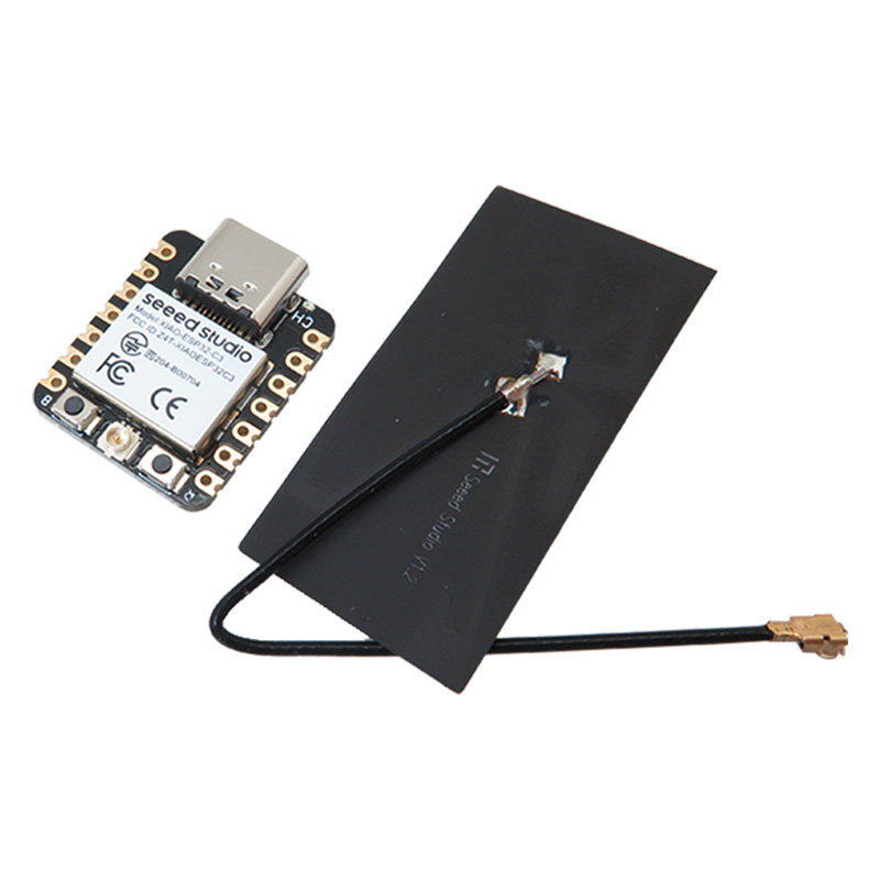
ESP32-C3 - I chose the ESP32-C3 mainly because of its built-in WiFi capability, which I will use to connect my robot car with the joystick.
- 2×
DC Motors - Torque vs Speed:
- Ease of Control:
- Practical Learning:
- Versatility:
- 2× Motor Drivers -
A4953 - They allow independent control of two motors
- Enable forward / backward movement (bidirectional control)
- Support PWM for speed control
- Can safely handle motor current (200mA+)
- Include internal protection, which is very important
- Battery -
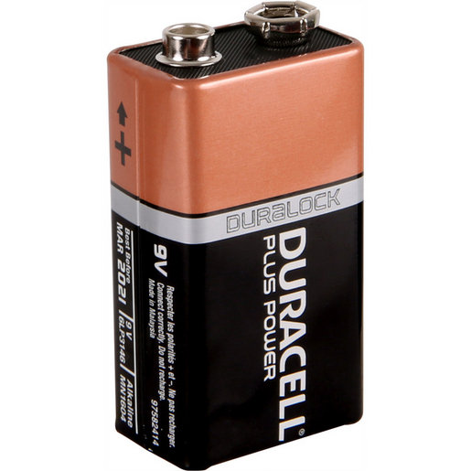
9 Volt Battery (Duracell) - Voltage Regulator -
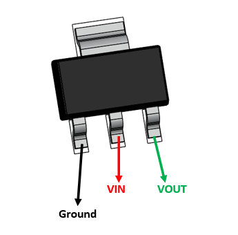
LM317 - I can control the output voltage precisely using resistors
- It provides stable voltage, which is very important for ESP32
- Has better current handling and thermal protection
- More flexible than fixed regulators
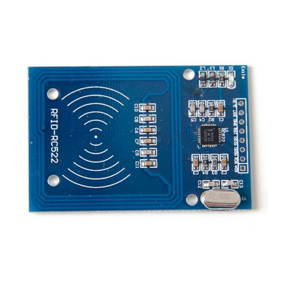
- NFC Reader -
RFID - RC522 - Detect coins
- Identify which coin
- Avoid counting duplicates
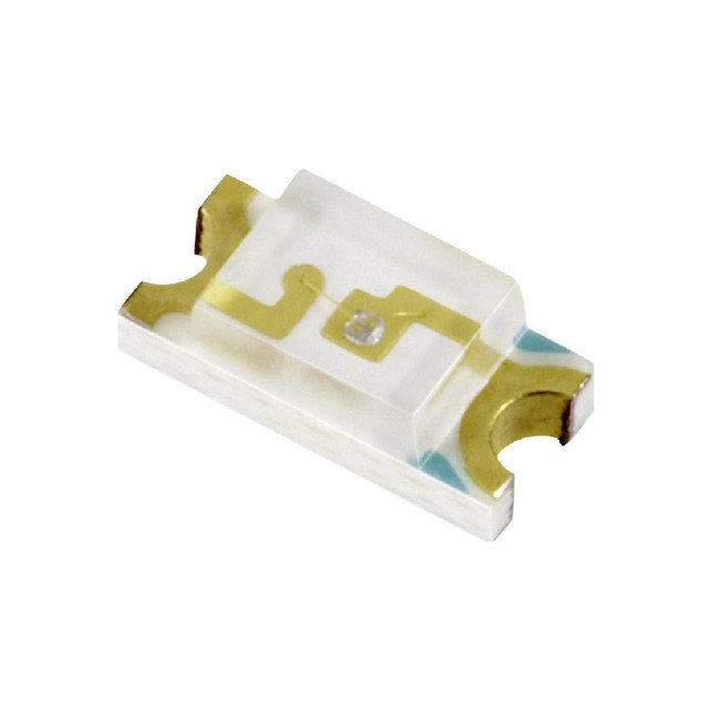
- LED - for battery indication
- It shows that power is working correctly
- Confirms that the microcontroller has booted
- And that the code is running
Also, it’s not just about WiFi 😄
It has enough GPIO pins, supports PWM for motor control, ADC for reading battery voltage, and can handle multiple tasks at the same time without problems.
For my project, where I need communication + control + logic all together, this felt like a very balanced choice.
After a lot of research, I chose these motors because:
The internal gearbox (around 1:48) converts high speed into usable torque, which is exactly what I need for a moving robot, not just spinning.
Compared to stepper motors, these are much easier to control — I just use PWM (Duty Cycle) to change speed.
They clearly show why we need motor drivers, which is one of the main learning goals of this week.
The dual shaft allows adding wheels on one side and possibly sensors or encoders on the other.
I used two A4953 H-Bridge drivers because:
I chose this battery because it is compact and easy to use.
For my robot design, it fits nicely and doesn’t make the system too complex. Also, it’s easy to replace and test with.
I used the LM317 adjustable regulator to convert 9V → 3.3V for the microcontroller.
Why this one:
This is a key part of my project because it allows the robot to read NFC tags (coins).
Each tag has a unique ID, so the robot can:
This makes my system much smarter compared to simple sensors.
I connected the LED to GPIO 20 of the ESP32-C3.
In my code, I set it to HIGH after setup, so:
It’s a small thing, but very useful for debugging 😄
By integrating all of these, I should have a PCB that drives the motors, runs on battery, and reads NFC tags.
I also initially planned to include a switch button (like in the joystick project) to turn the system on and off. Since I previously mentioned that the switch button footprint was incorrect, I created a new footprint and even printed it on paper to verify it.
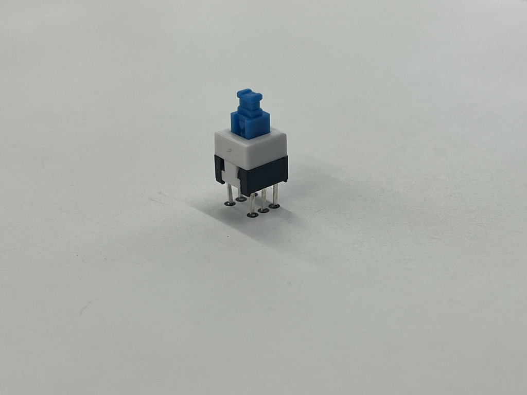
However, later I realized that this type of switch was not suitable for this PCB, so I switched to a simple 2-pin toggle button. But I still want to mention that I created a new footprint 😃
Output Device Exploration — DC Motor
The main output device I am testing and using this week is the DC Motor — it's the core actuator that lets my RC robot actually move.
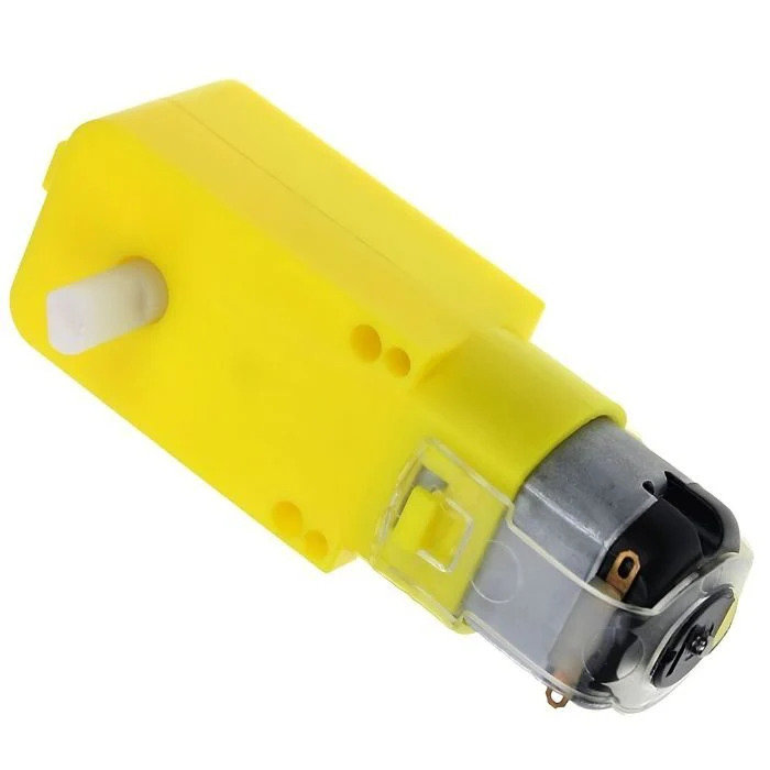
Working principle:
A DC motor converts electrical energy into mechanical (rotational) energy. Inside the motor there is a fixed magnetic field, created either by permanent magnets or field windings (the stator), and a coil of wire that can rotate inside that field (the rotor/armature).
When DC current flows through the rotor coil, each current-carrying wire sitting inside the magnetic field experiences a force — this is the motor effect, described by the Lorentz force law (F = I·L × B). Because the coil is wound around a shaft, these forces don't cancel out; instead they create a torque that spins the shaft.
A component called the commutator (together with brushes) continuously reverses the direction of current in the rotor coil as it spins, so the torque keeps acting in the same rotational direction instead of the motor just oscillating back and forth.
- Reversing the polarity of the applied voltage reverses the direction of rotation.
- Controlling the
average voltagedelivered to the motor — viaPWM (Pulse Width Modulation)— controls its effective speed, since the motor responds to the average power rather than instantaneous switching. - The gearbox inside my motor (~1:48 ratio) trades rotational speed for torque, since a raw DC motor spins very fast but with very little torque — not usable for a robot car by itself.
Datasheet: DC Gear Motor Datasheet
Buying link: Where I bought this motor
Why I Need an H-Bridge Motor Driver
A microcontroller GPIO pin can only source a few milliamps to tens of milliamps and outputs a fixed direction of current. A DC motor, on the other hand, needs:
- More current than a GPIO pin can safely provide (my motors draw around
180 mAunder load, measured with a multimeter). - Bidirectional control — the ability to reverse current direction through the motor to drive it forward and backward.
- Protection from the motor's own back-EMF (the voltage spike a motor generates when it's suddenly stopped or reversed), which can damage the driving electronics if not handled.
This is exactly what an H-bridge solves. It's called an H-bridge because of the "H" shape formed by its four switches (transistors/MOSFETs) around the motor:
- Turning on one diagonal pair of switches drives current through the motor in one direction (forward).
- Turning on the opposite diagonal pair reverses the current (backward).
- Turning off all switches, or shorting both motor terminals together, stops/brakes the motor.
I used two A4953 H-bridge driver ICs — one per motor — because they integrate all four switches plus current sensing and thermal/overcurrent protection into a single small package, and they accept a simple PWM input directly from the ESP32-C3 GPIO to control speed, with a separate direction pin.
Motor driver datasheet: A4953 Datasheet
Buying link: Where I bought the A4953 driver
Now let’s go into the process of building RC version 2.
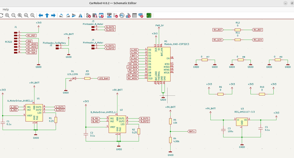
I searched for all components in KiCad Schematic Design.
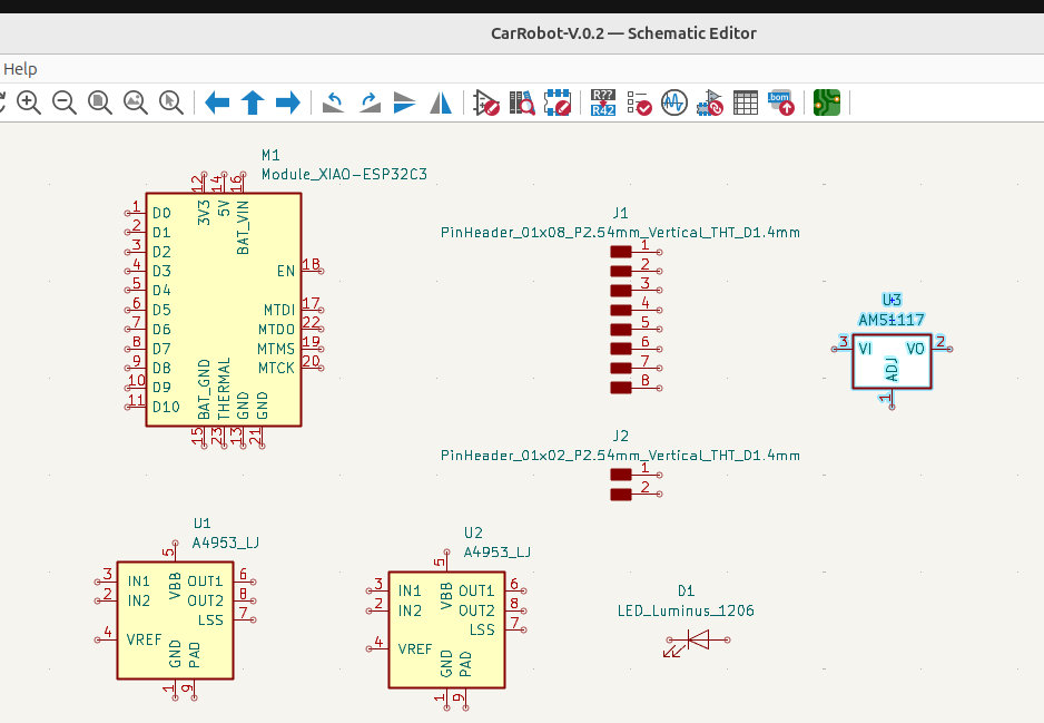
By studying the documentation(ESP32-C3 Documentation, A4953 Documentation, LM317 Documentation, RC522 Documentation), I understood how each component should be connected. I completed the schematic and then moved to the PCB design.
This part took quite a long time because I wanted to make the design compact and well-organized.
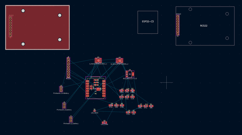
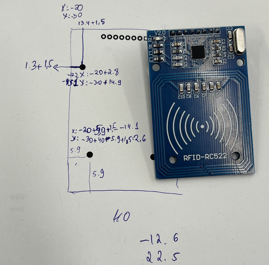
Again, I needed to modify the RC522 footprint, because I wanted to create mounting holes on my PCB similar to the actual RC522 module. The downloaded footprint didn’t match my real component, so I adjusted the hole positions manually.
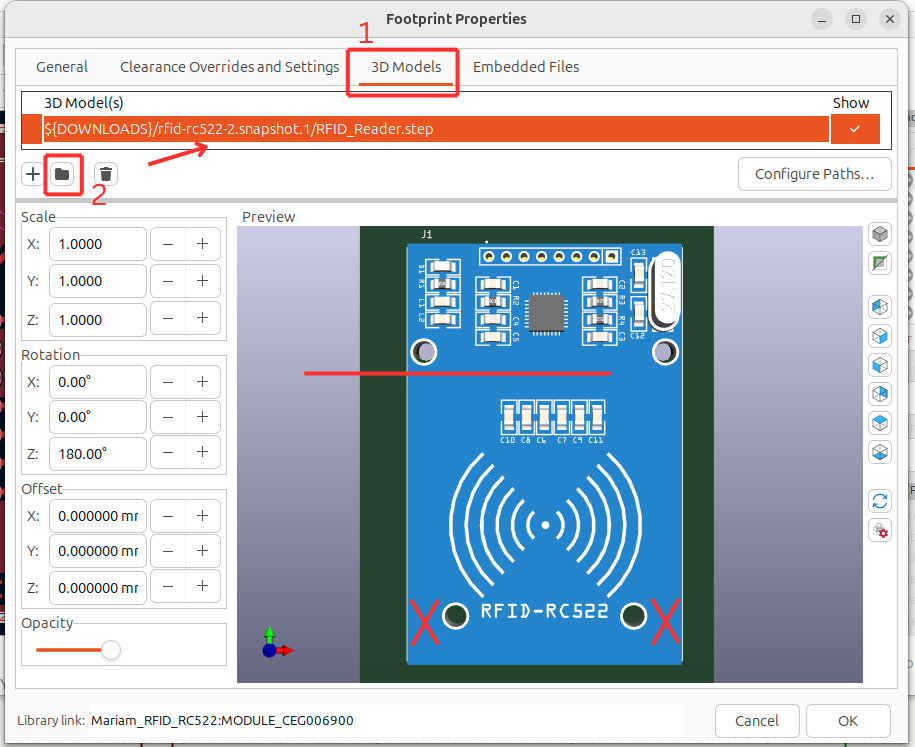
I downloaded the RFID-RC522 footprint. After selecting my component and pressing “E”, I opened the properties window and from the top section chose the “3D Models” tab. Then, by clicking the “” button, I added the .step file from the downloaded folder.
After that, I noticed that the holes in the model did not match the holes on my actual RC522 module.
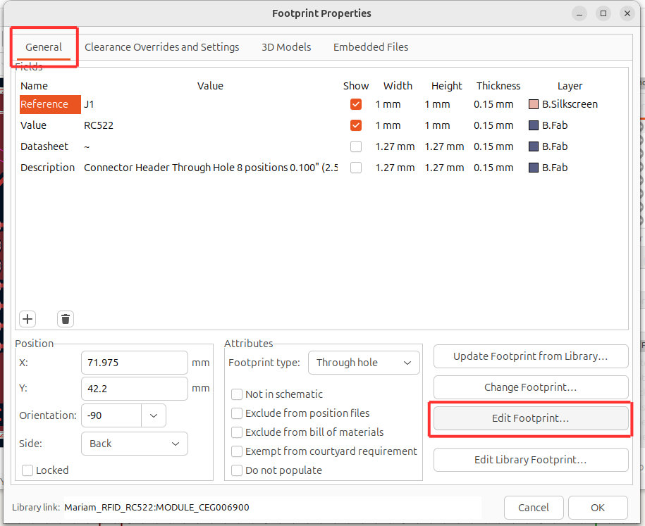
To fix this, I opened the same window and from the “General” tab clicked on “Edit Footprint”.
In the opened editor, I adjusted the positions of the mismatched holes to match the actual holes on my RC522 module.
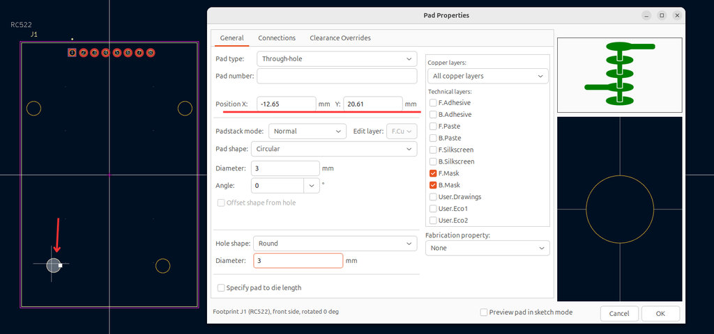
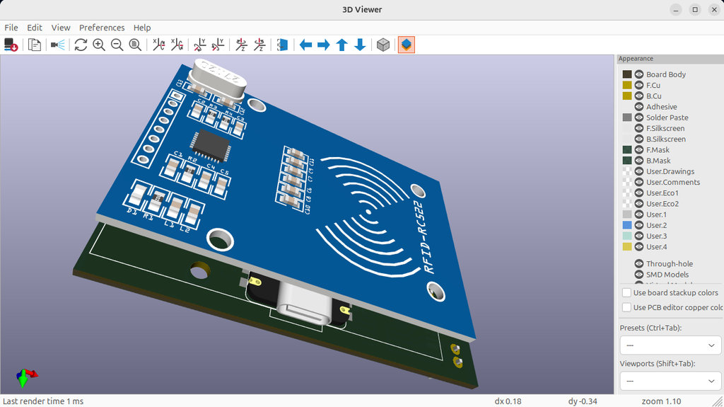
Then, to verify, I reopened the “3D Models” tab and confirmed that the holes now correctly align.
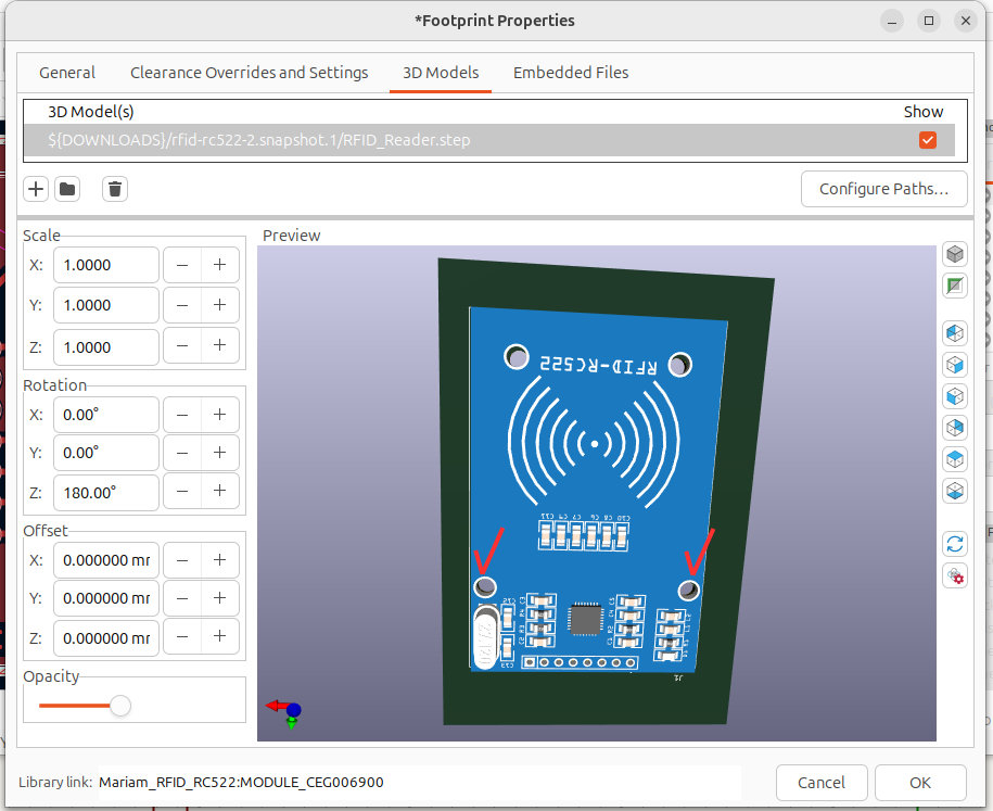
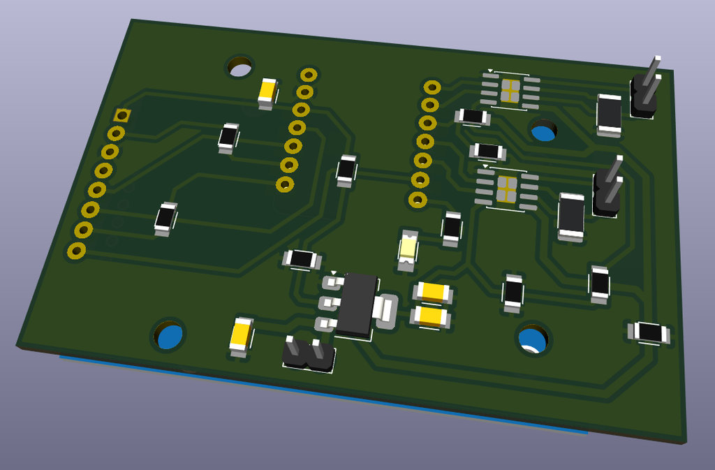
Here is the final 3D view. I also set the Z offset to 7 mm in the “3D Models” tab to create enough distance from the PCB, since I am mounting the ESP32-C3 on the opposite side (same side as the RC522).
Everything was ready — time for engraving and cutting.
Based on my previous issues, when preparing the F.Cu file in mods, I directly set the cut depth to 0.25mm to be sure that the engraving would work properly.
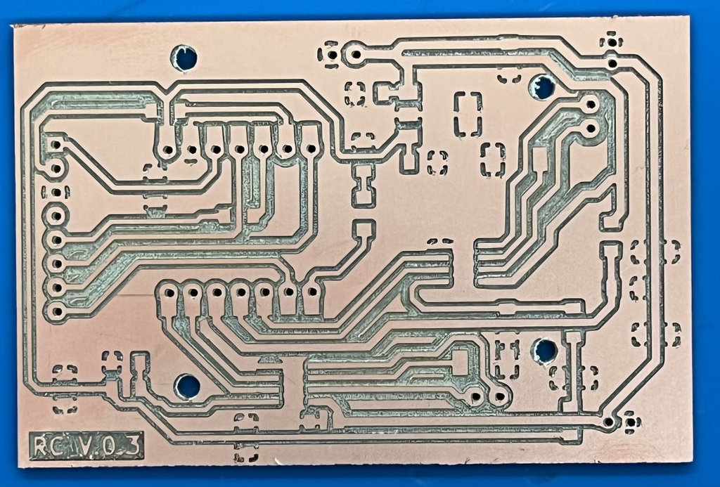
And this time, it worked — the PCB milling process went smoothly.
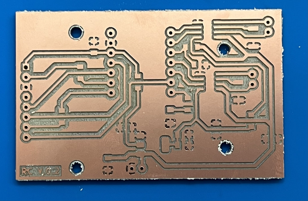
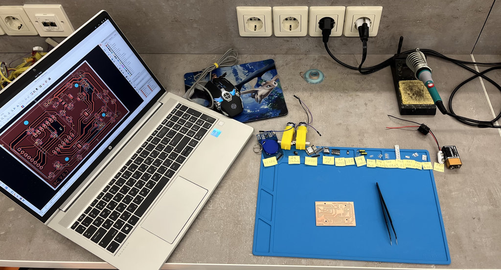
Now the workspace is ready for soldering.

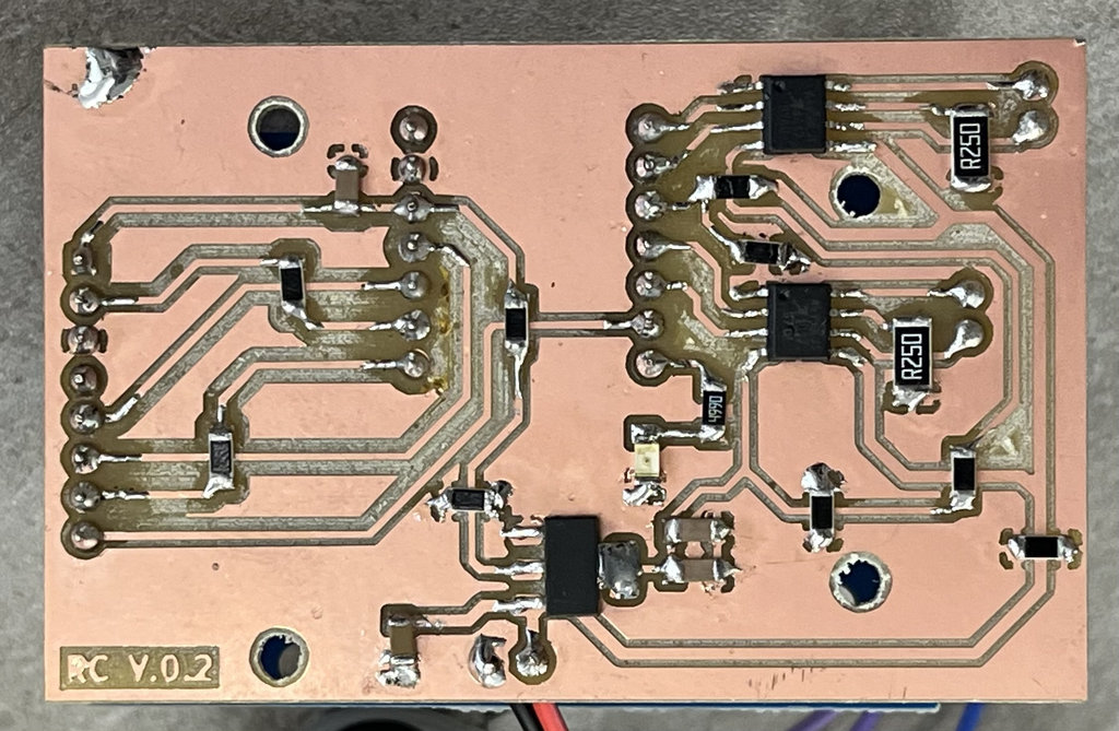
And here is the final result.
Now the PCB is ready to be programmed.
To verify that all components are connected correctly, I immediately wrote a code. The goal was that my PCB should run using the connected battery, both motors should drive, and when I bring an NFC tag close to the NFC reader, the motors should stop. I also implemented control using a toggle button to turn the whole system on and off.
However, during testing, I noticed that one of the motors is not working. I will try to understand and fix this issue a bit later.
AI prompt:
"Write ESP32-C3 Arduino code that drives two DC motors through A4953 H-bridge drivers using PWM speed control, reads an MFRC522 NFC/RFID reader over SPI, stops both motors for 3 seconds when a tag is detected and then drives forward again, and toggles a status LED based on a battery on/off toggle switch."
I gave Claude the pin numbers I'd already assigned in KiCad, and it returned the base structure — I then adjusted the SPI pin assignment for the ESP32-C3's strapping pins (GPIO8/GPIO9) so the board wouldn't hang on boot, and tuned the PWM speed value through testing.
#include <SPI.h>
#include <MFRC522.h>

// --- PIN DEFINITIONS ---
#define MOTOR_A_IN1 3
#define MOTOR_A_IN2 2
#define MOTOR_B_IN1 6
#define MOTOR_B_IN2 5
#define BAT_TOGGLE  4
#define LED_BATT    21

#define RC522_SDA   7
#define RC522_RST   8
#define RC522_SCK   20
#define RC522_MISO  9
#define RC522_MOSI  10

// --- PWM SETTINGS ---
const uint32_t PWM_FREQ = 5000;
const uint8_t  PWM_RES  = 8; // 8-bit (0-255)

MFRC522 mfrc522(RC522_SDA, RC522_RST);

void setup() {
// CRITICAL: Prevent boot hang on strapping pins
pinMode(8, OUTPUT);
digitalWrite(8, HIGH);
pinMode(9, INPUT_PULLUP);

Serial.begin(115200);
delay(1000);
Serial.println("System Starting...");

// 1. New API: ledcAttach combines setup and pin attachment
// Format: ledcAttach(pin, frequency, resolution)
ledcAttach(MOTOR_A_IN1, PWM_FREQ, PWM_RES);
ledcAttach(MOTOR_B_IN1, PWM_FREQ, PWM_RES);

// 2. Direction Pins
pinMode(MOTOR_A_IN2, OUTPUT);
pinMode(MOTOR_B_IN2, OUTPUT);
stopMotors();

// 3. Battery Toggle & LED
pinMode(BAT_TOGGLE, INPUT);
pinMode(LED_BATT, OUTPUT);

// 4. SPI & RC522
SPI.begin(RC522_SCK, RC522_MISO, RC522_MOSI, RC522_SDA);
mfrc522.PCD_Init();

Serial.println("Motors part.");
Serial.println("Ready! Scan an NFC Tag.");
}

void loop() {
bool isToggleOn = digitalRead(BAT_TOGGLE);
digitalWrite(LED_BATT, isToggleOn ? HIGH : LOW);

if (mfrc522.PICC_IsNewCardPresent() && mfrc522.PICC_ReadCardSerial()) {
Serial.println("NFC Tag Detected!");

if (isToggleOn) {
stopMotors();
delay(3000);
driveForward(220);
}

mfrc522.PICC_HaltA();
mfrc522.PCD_StopCrypto1();
}
delay(50);
}

void driveForward(int speed) {
// In API v3.0+, ledcWrite uses the PIN number instead of a channel
ledcWrite(MOTOR_B_IN1, speed);
digitalWrite(MOTOR_B_IN2, LOW);

ledcWrite(MOTOR_A_IN1, speed);
digitalWrite(MOTOR_A_IN2, LOW);
}

void stopMotors() {
ledcWrite(MOTOR_A_IN1, 0);
digitalWrite(MOTOR_A_IN2, LOW);
ledcWrite(MOTOR_B_IN1, 0);
digitalWrite(MOTOR_B_IN2, LOW);
}
To understand why the second motor was not working, I used the multimeter again. I found that the Sense Pin (LSS) of the second motor’s driver, which I connected to GND through a resistor, was actually not properly grounded. The GND trace was broken during the milling process.
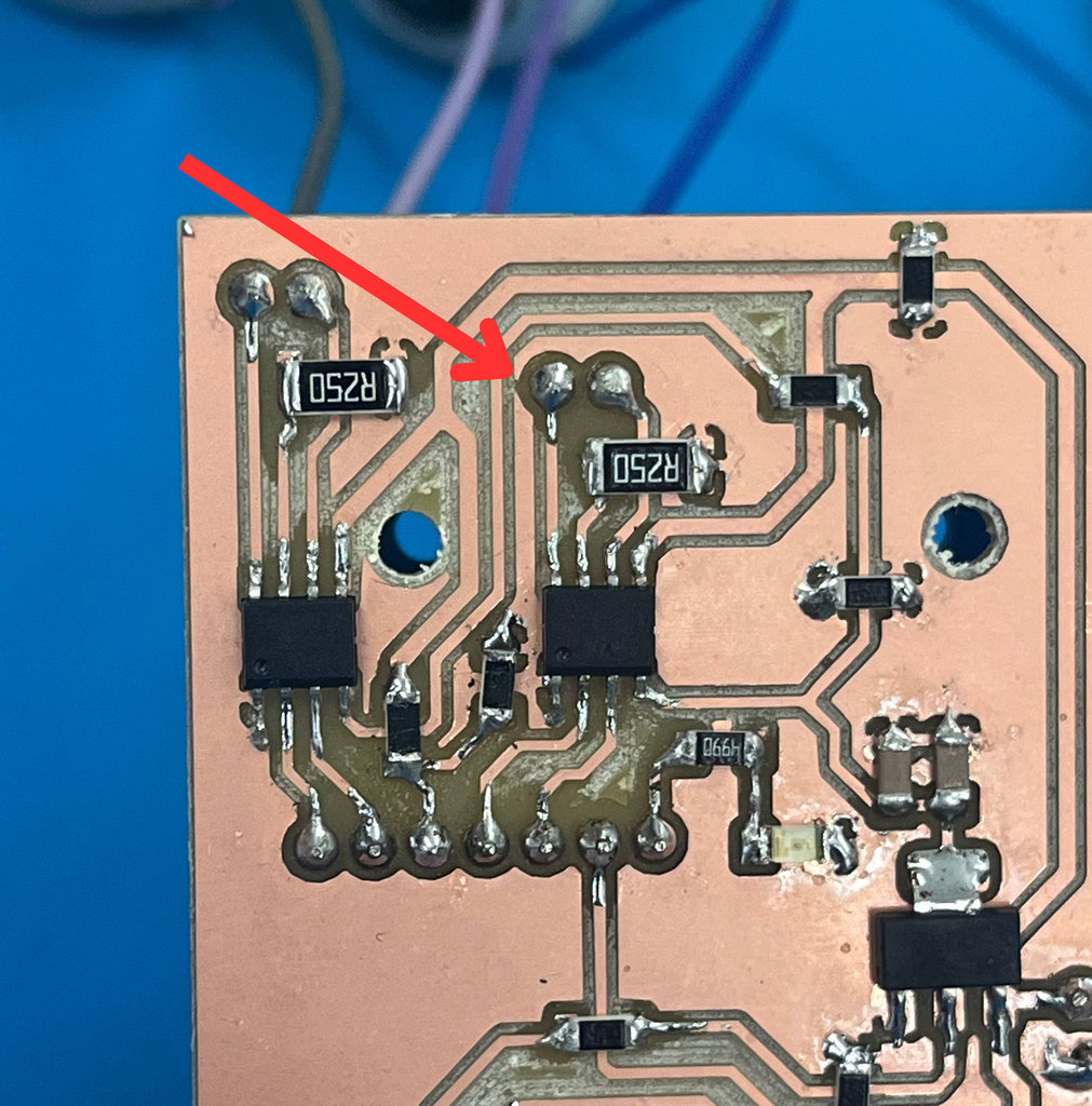
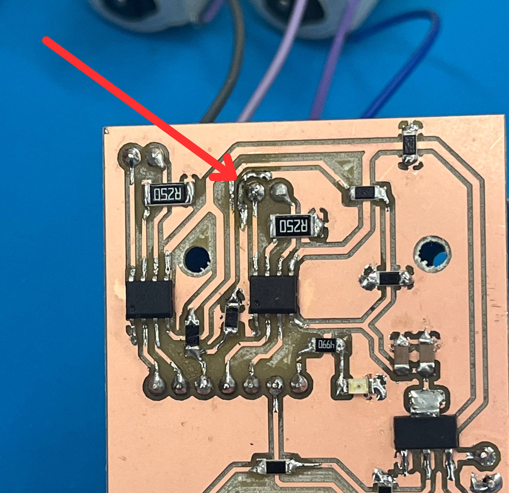
To fix this, I used a small wire and carefully probed the connection to restore the path.
At that moment, everything seemed perfect, and I thought this was my only issue and everything should work now.
So I connected my PCB again to the power supply, and finally, the second motor started working too… but only for about 5 seconds 😰
Then my PCB became very hot, and unfortunately, that was its last moment 🥵
Now I have a hypothesis:
Initially, the regulator should have been connected differently, probably using a proper 5V regulation stage with a more suitable regulator.
Also, the battery ‘+’ should have been stabilized to GND through a larger capacitor. I used a 100µF capacitor, but now I think I should use a bigger one to handle the load better.
In short, I need to go deeper into the physics and power design, but at the same time, I’m actually happy — because I’m learning through real mistakes and getting real practical experience 😄
Let’s wait for RC version 3 ...😄
After 2 days, the new PCB design is ready. Let me explain the changes I made:
- First, I now use the
3.3Vfrom theESP32-C3 only for the NFC Reader, and the5Vline for themotor drivers. - Because of this, I also changed the regulator type to
LM2940 (5V, SOT-223). - I also added an
electrolytic capacitor 1000µFto the9V batteryto improve power stability.
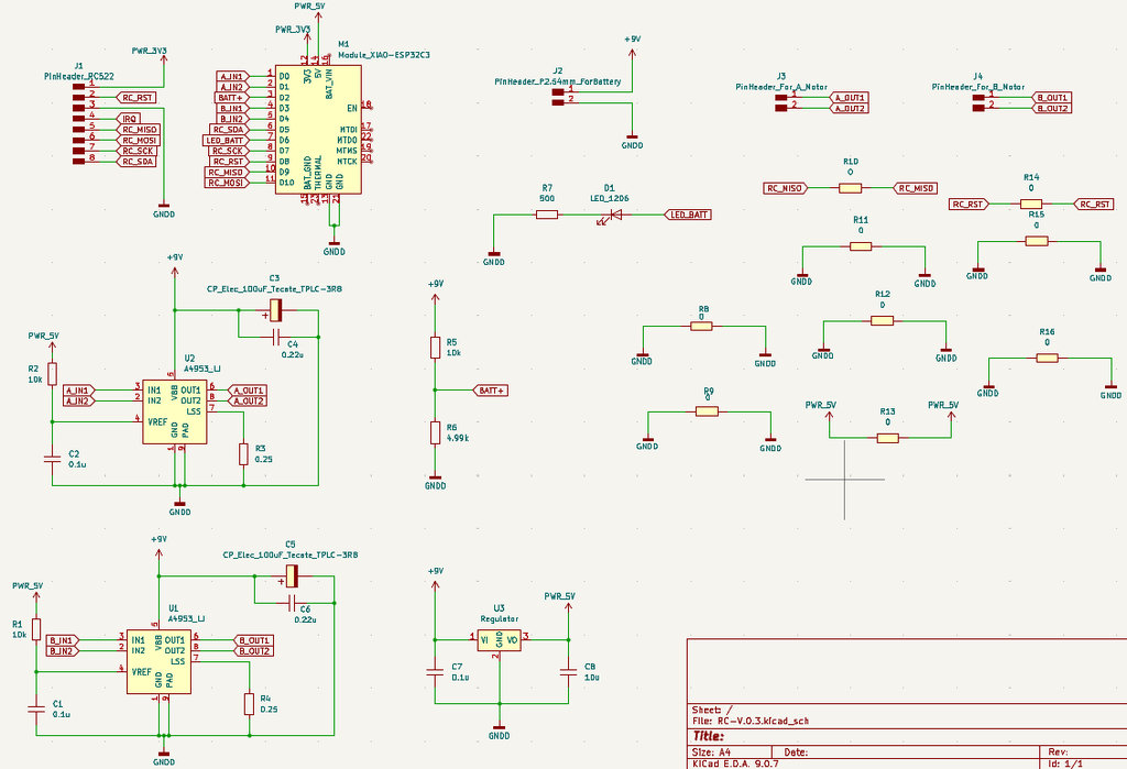
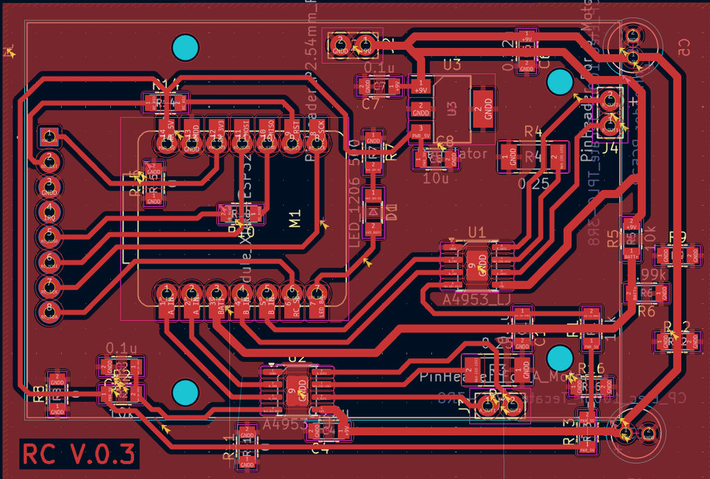
Here is the final Schematic Design and PCB Design.
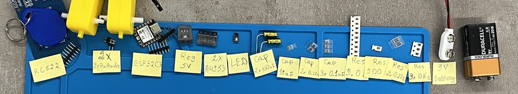
After cutting the PCB, it was time to solder all the components. So first, I organized everything заранее, and my workspace was ready.
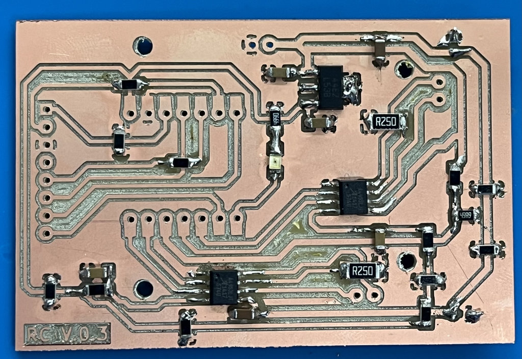
And finally, back again to the programming process. Since I didn’t change the pin configuration, I used the same code I wrote before — the one that controls the motors and stops them when an NFC tag is detected — and uploaded it to RC V.0.3.
But… things were not that easy 😅
After struggling for a few hours, Onik helped me, and here are the mistakes he found and fixed:
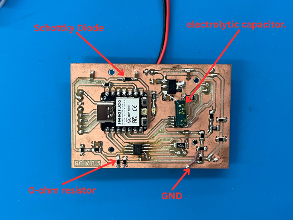
- 1. Added a Schottky Diode
- 2. Motor Driver Issue
- 3. Voltage Stability Improvement
He added a Schottky diode between the 5V line and the regulator.
Why this was important:
Since my PCB had already burned once, one possible reason was that I was powering the board both from USB (5V) and from a 9V power supply at the same time, which could cause overload or reverse current.
This Schottky diode prevents voltage from flowing back from the regulator into the ESP32-C3, protecting the system.
Since only one motor was working and the other was not responding at all, I used a tester (multimeter) to check the voltages going into and out of the motor driver connected to the non-working motor.
We noticed that the VREF pin of the motor driver had around 5.3V, and the GND, which should be directly connected to the common ground, was connected through a 0-ohm resistor.
Even though it’s called 0-ohm, it still introduces a tiny resistance, which can cause voltage fluctuations. These small fluctuations can “confuse” the logic part of the driver.
To fix this, I added another 0-ohm resistor to help stabilize the connection.
I had already connected the 5V output of the regulator with a 10µF capacitor, but to make the system more stable, I added an additional 10µF electrolytic capacitor.
When motors start or work under load, they draw instant high current spikes. The voltage regulator cannot always respond fast enough to these changes.
The electrolytic capacitor helps by providing stored energy at that exact moment, preventing voltage drops (voltage sag) and avoiding unexpected ESP32 resets (reboots).
After all of this, I was finally able to run both motors 🎉
But… after a short time, the NFC Reader stopped working 😳
Anyway, I will include a video showing the motors working, and for now, let’s consider this week finished… while waiting for RC version 4 😆
This week I focused on improving my RC car PCB and bringing it closer to a real working system. I didn’t just design — I actually tested, failed, fixed, and tested again (and again 😄).
I learned that designing a PCB is one thing, but making it work in real life is completely different. Power distribution, current consumption, heat, and small mistakes like broken traces can completely destroy the system (literally 🥵).
One of the most important things I understood this week is how critical power management is. Motors consume much more current than I first expected, and if I don’t calculate everything correctly — battery, regulator, and traces — the whole PCB can fail. And yes… mine did 😅
At the same time, debugging with tools like a multimeter helped me understand problems much deeper. For example, finding a broken GND line or understanding why a motor is not working — these were very valuable learning moments.
Individual assignment

AI prompt:
“And when she ended the week 10”