
Final Project
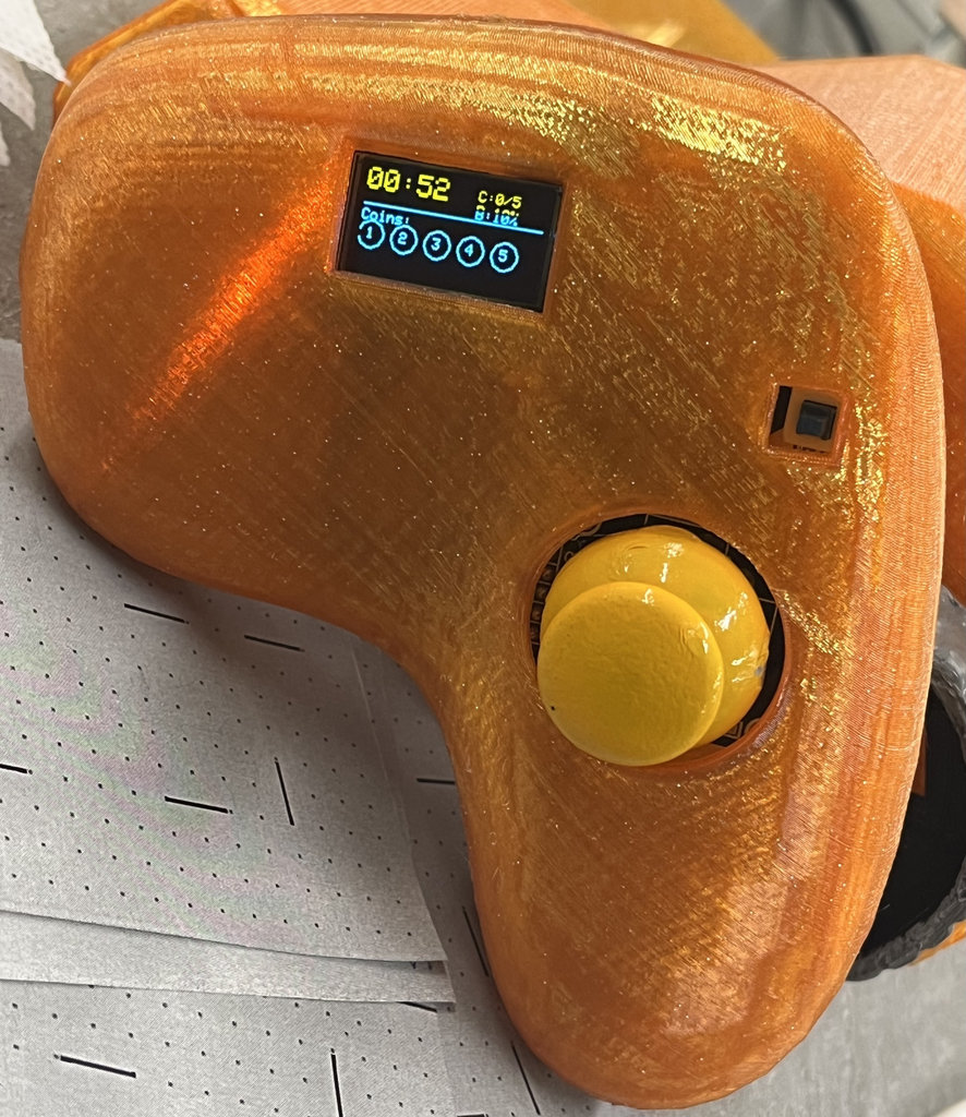
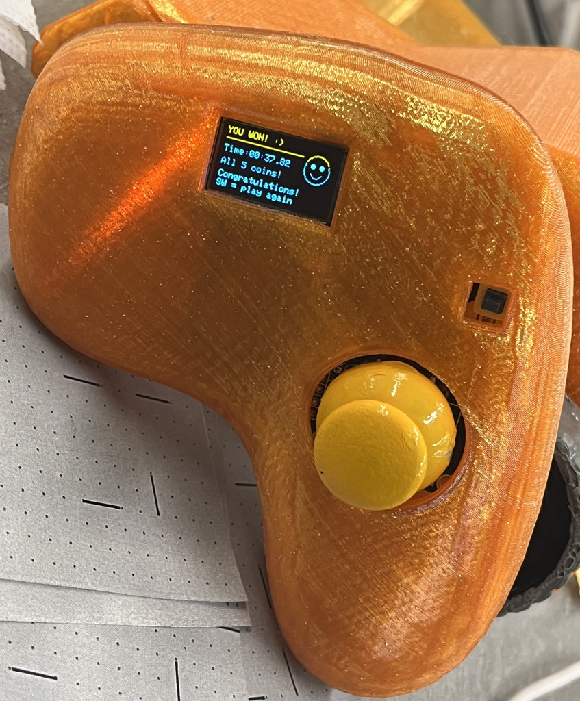
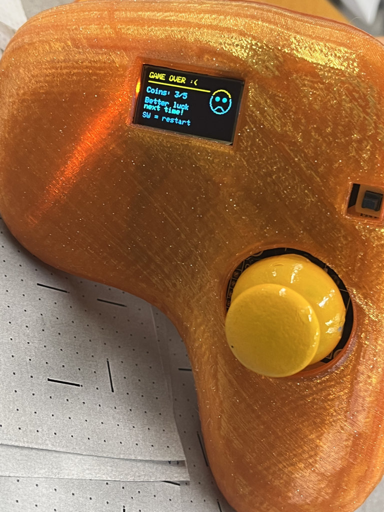
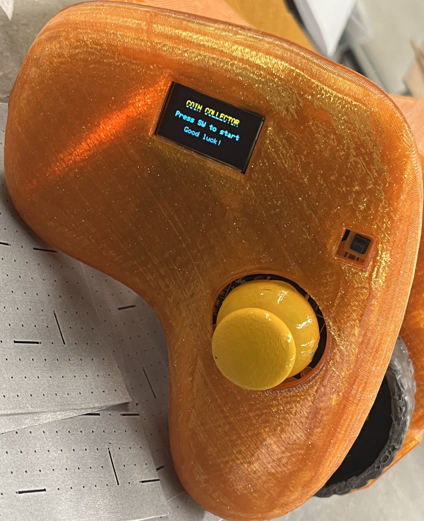
The complete game is now working end-to-end. Joystick controls the car wirelessly, NFC tags are detected as coins, the OLED shows live game state, and both devices flash their LEDs on coin collection. WIN screen shows your time. GAME OVER shows coins collected. Press SW to restart anytime.
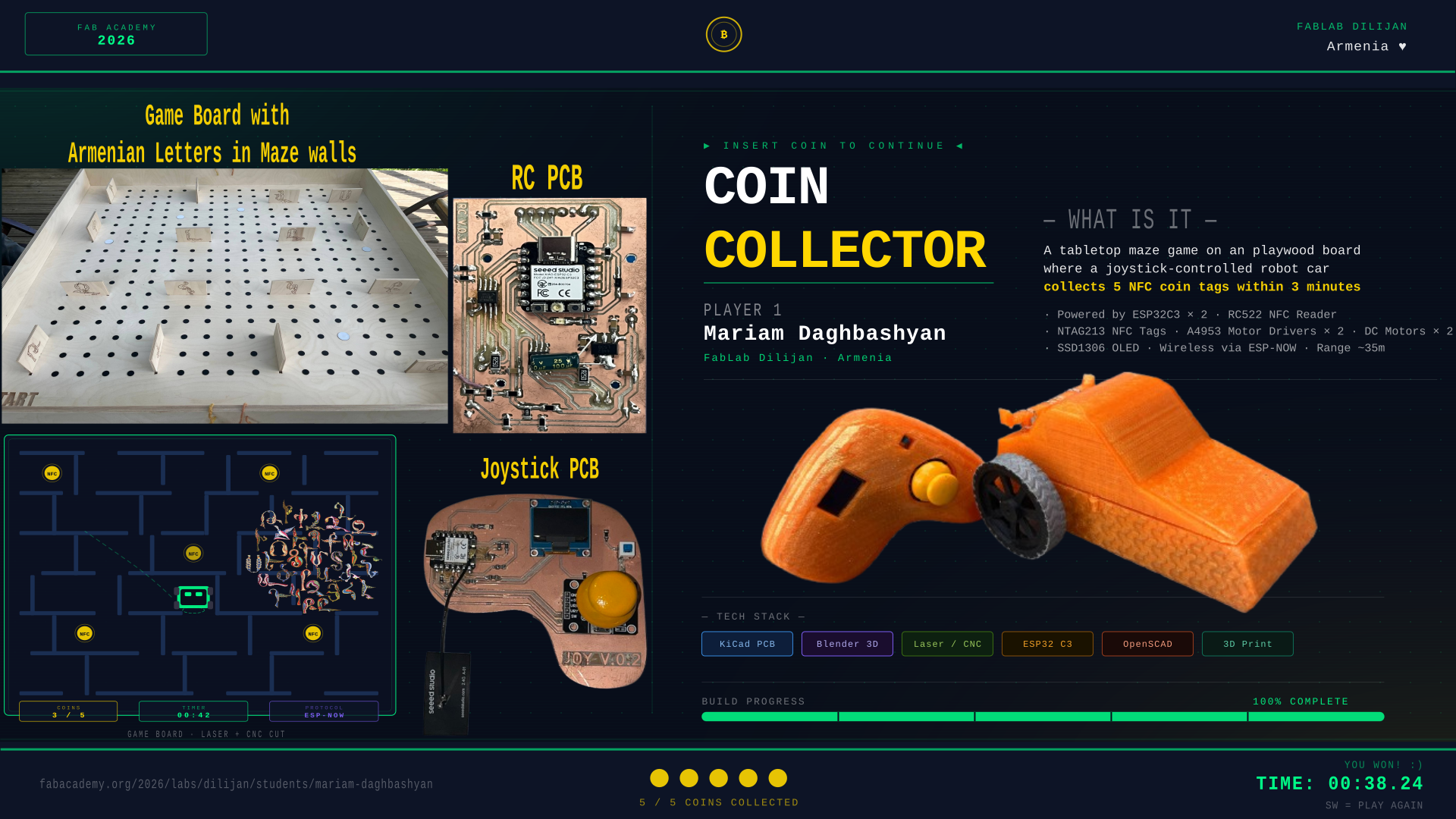
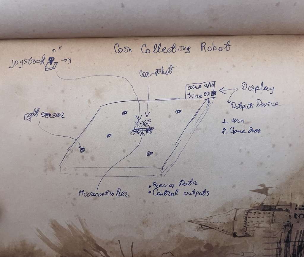
Finally, coming back to the present day, I feel confident about what my final project will be. After realizing that politics is not something I want to focus on, I decided to create a game that helps people relax and think about positive things.
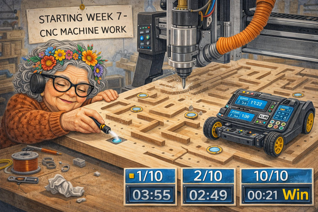
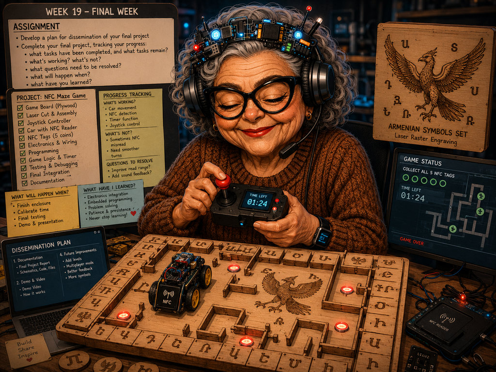
The game is built on an MDF board, featuring a robot controlled by a joystick. The goal is to collect 5 NFC coin tags within a limited time. Each coin is a unique NTAG213 sticker detected by an RC522 NFC reader mounted under the car. Collect all 5 before 00:00 to win — miss any and it's GAME OVER.
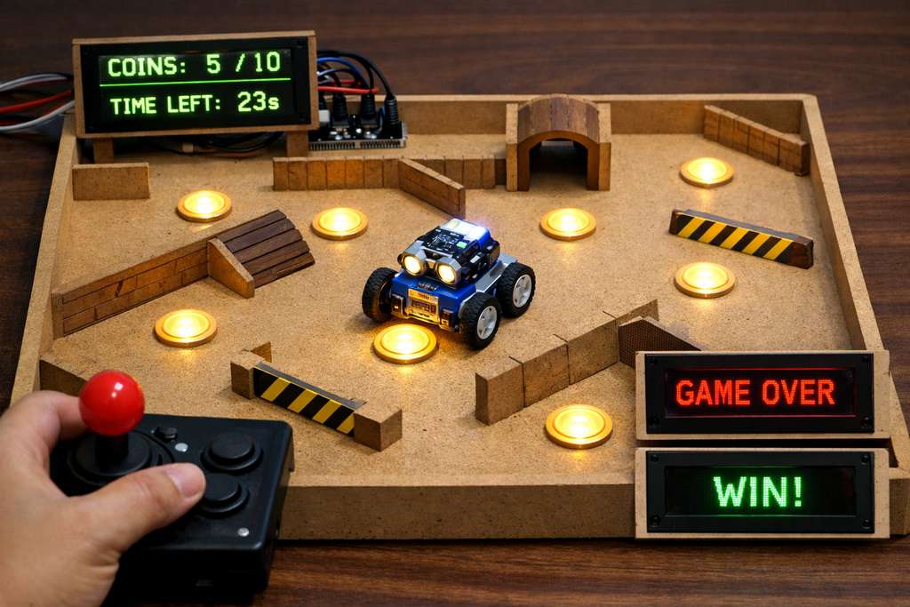
▸ AI prompt: "Generate a photorealistic image of a tabletop maze game made from wood, featuring a small robotic car collecting glowing coins, obstacles, and walls..."
COLLECTOR
| COIN # | TAG UID | TYPE | STATUS |
|---|---|---|---|
| 01 | 1D 05 99 C5 08 10 80 | NTAG213 | ■ COLLECTED |
| 02 | 1D 02 99 C5 08 10 80 | NTAG213 | ■ COLLECTED |
| 03 | 1D 04 99 C5 08 10 80 | NTAG213 | ■ COLLECTED |
| 04 | 1D F7 98 C5 08 10 80 | NTAG213 | ■ COLLECTED |
| 05 | 1D 03 99 C5 08 10 80 | NTAG213 | ■ COLLECTED |
 Computer Aided Design
OpenSCAD — Maze Design
DONE
▶
Computer Aided Design
OpenSCAD — Maze Design
DONE
▶
I already had a clear idea of how I wanted the game environment to look.
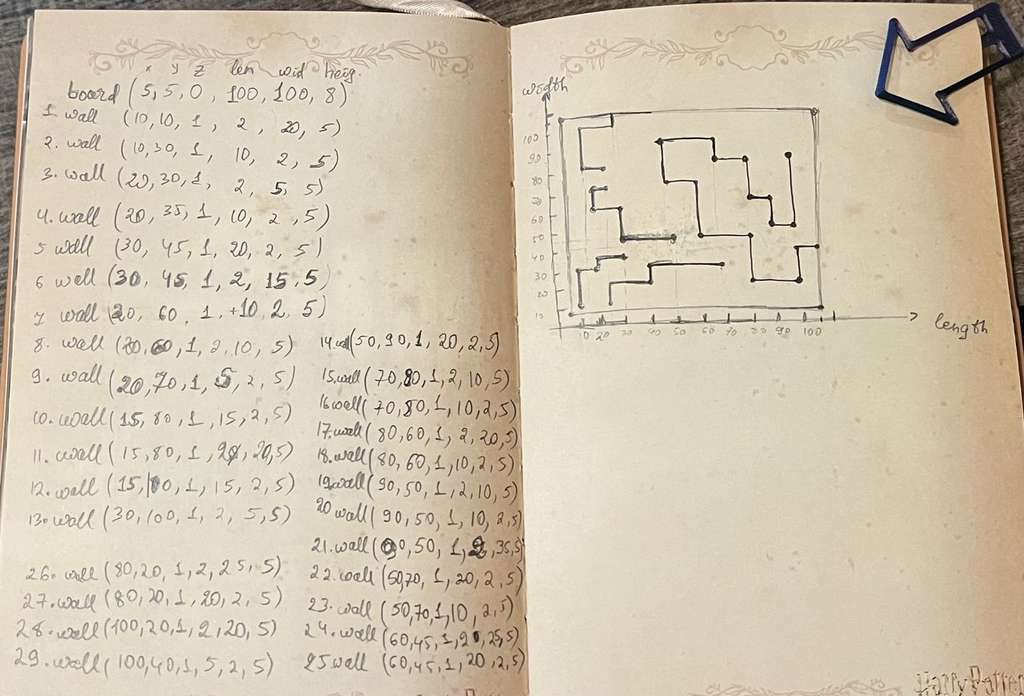
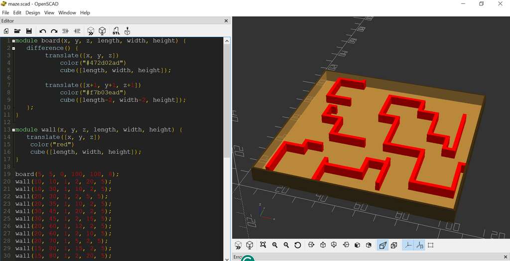
During this week, I learned OpenSCAD and transferred my ideas onto paper, then modeled them digitally.
 Computer Controlled Cutting
Laser Cut — 300×300mm Prototype
DONE
▶
Computer Controlled Cutting
Laser Cut — 300×300mm Prototype
DONE
▶
I improved my OpenSCAD skills and modified my design.
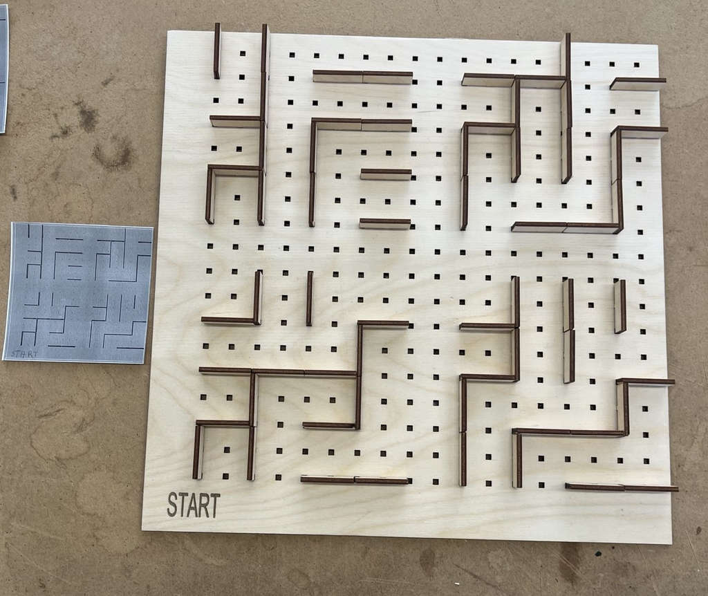
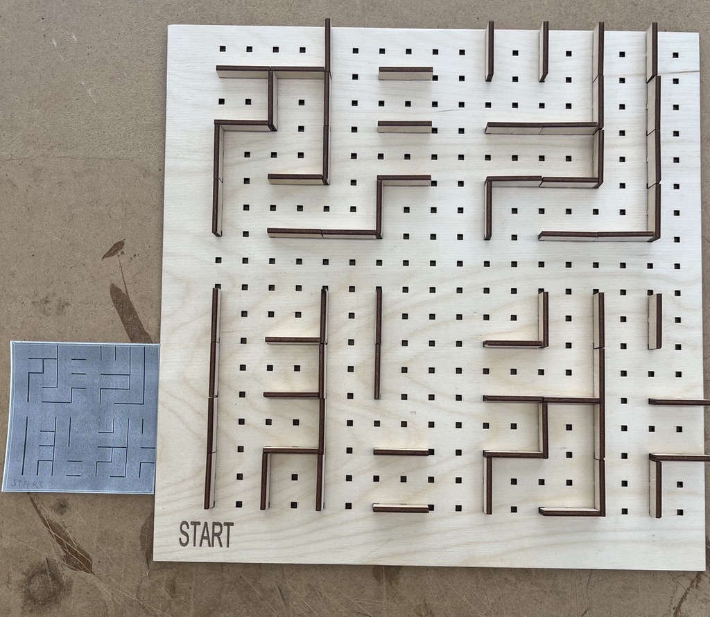
I created an algorithm to generate the labyrinth randomly, so each run produces a different layout.
I used a laser cutter to make a 300mm × 300mm test version and also created cards generated from random designs.
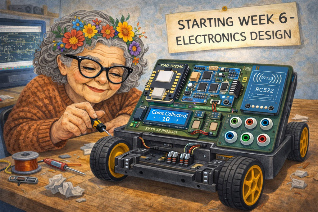 Electronics Design
PCB Design — Motors + NFC + LCD
DONE
▶
Electronics Design
PCB Design — Motors + NFC + LCD
DONE
▶
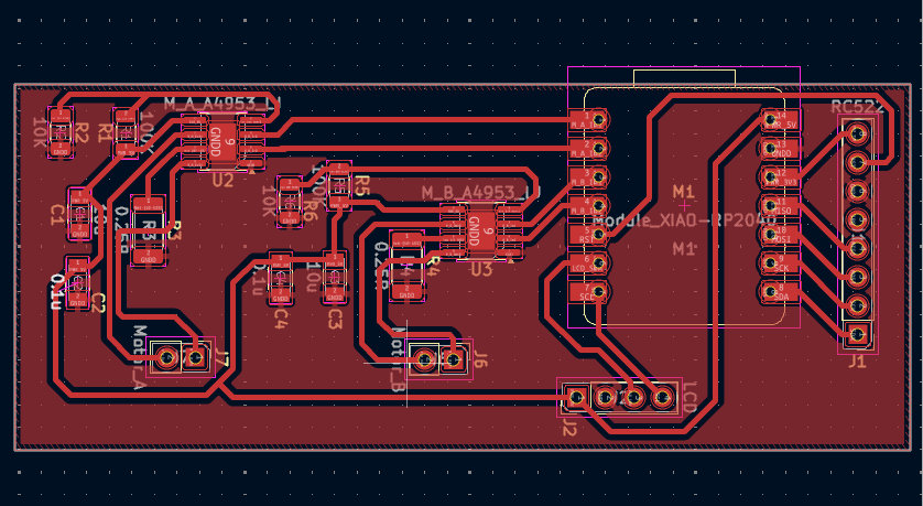
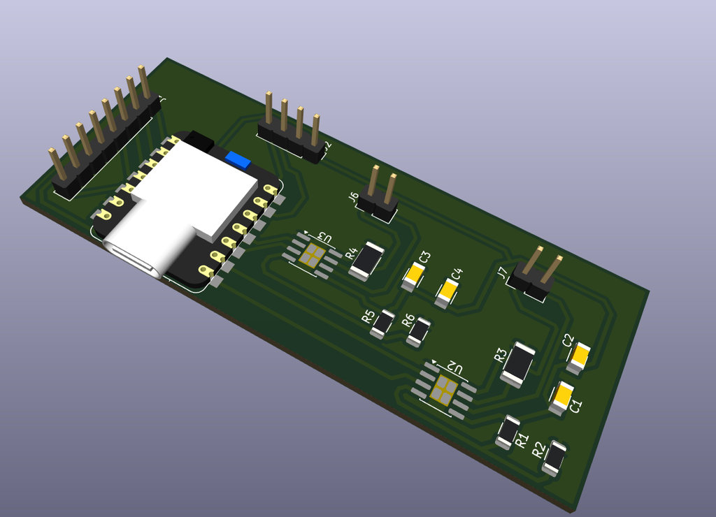
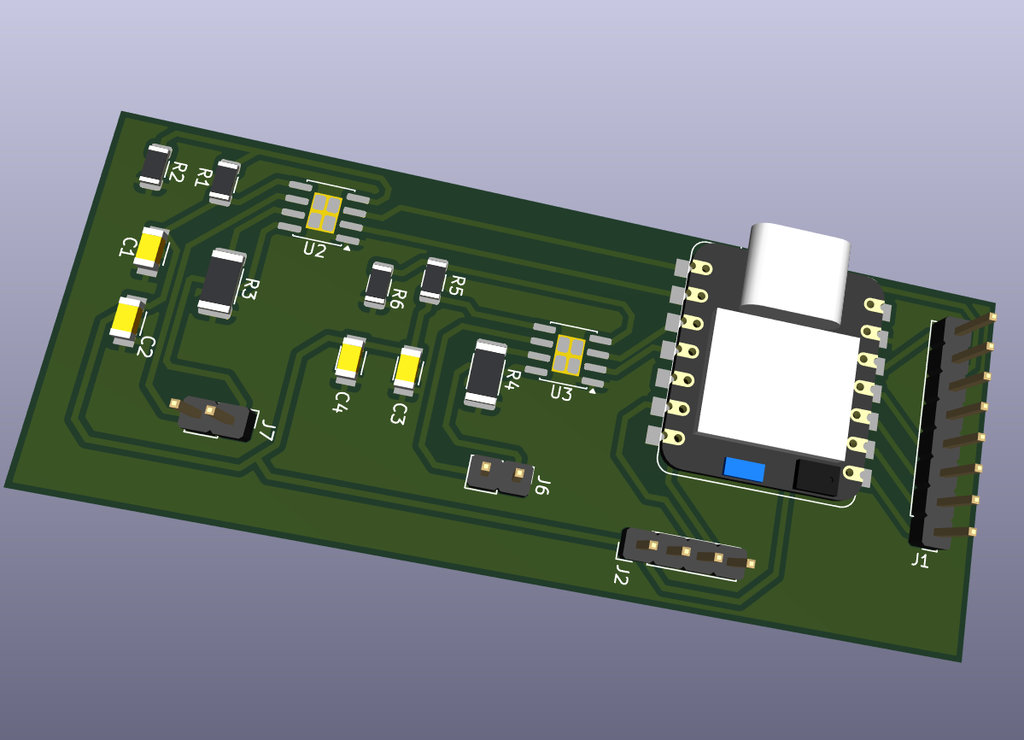
This week, I worked on a more serious part — designing the PCB for my robot car, which includes:
LCD (timer + coins display), NFC reader RC522 (coin detection),
2 motor drivers (movement), and RP2040 microcontroller (main logic).
 Computer-Controlled Machining
CNC Cut — Full Game Board
DONE
▶
Computer-Controlled Machining
CNC Cut — Full Game Board
DONE
▶
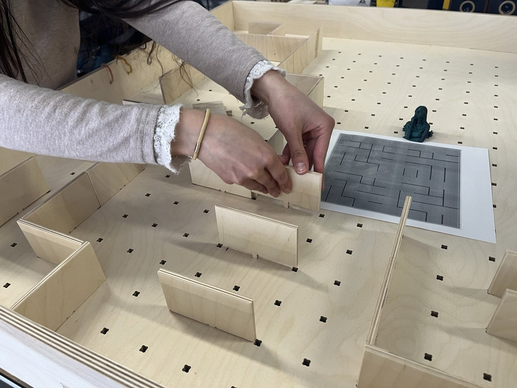
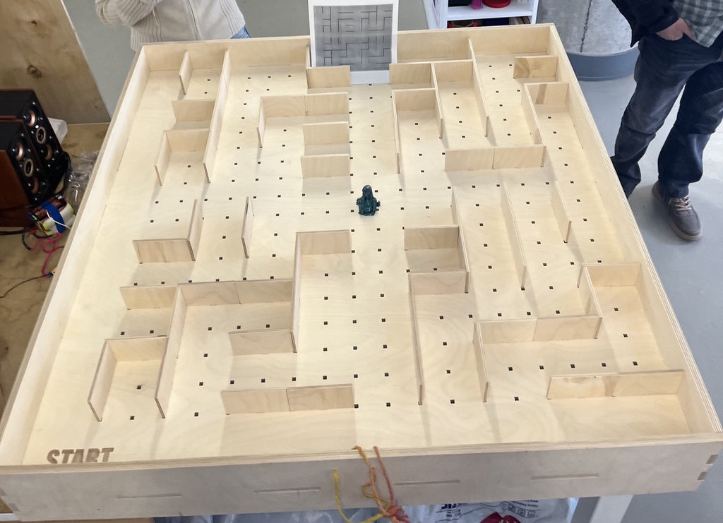
This week, I got much closer to the final result by using a CNC machine to cut a larger,
more refined version of the game board that I initially tested in Week 3.
 Electronics Production
PCB Milling + NFC Working
DONE
▶
Electronics Production
PCB Milling + NFC Working
DONE
▶
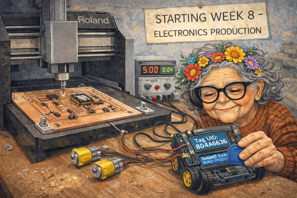
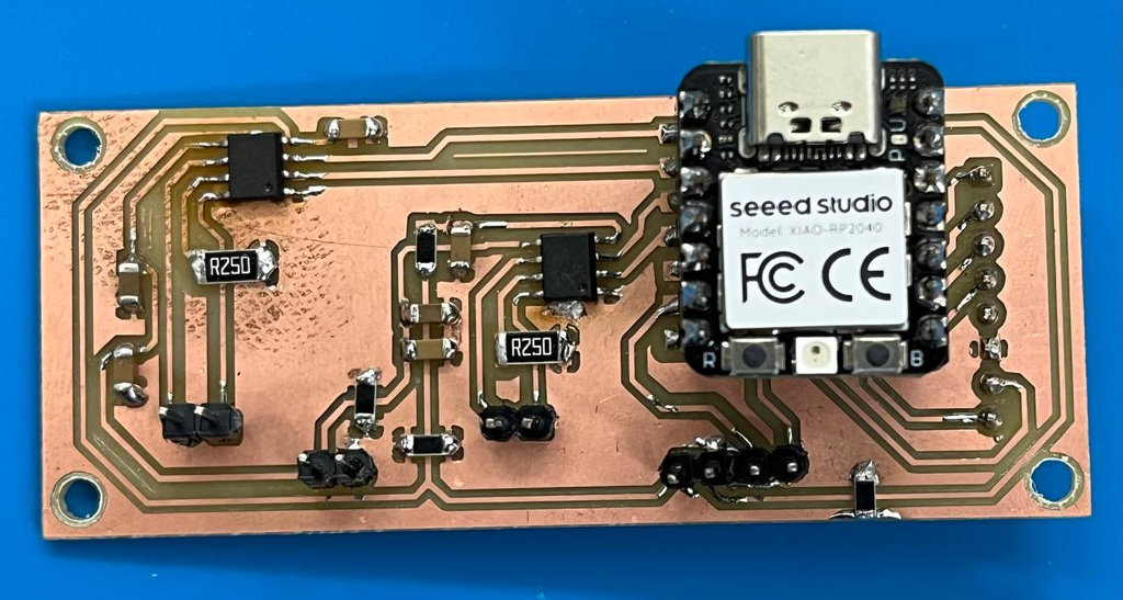
This week, I milled the PCB design, which I plan to further improve and optimize in the coming weeks.
The NFC reader is now working and detecting tags reliably.
 Input Devices
Joystick + OLED + ESP-NOW Link
DONE
▶
Input Devices
Joystick + OLED + ESP-NOW Link
DONE
▶
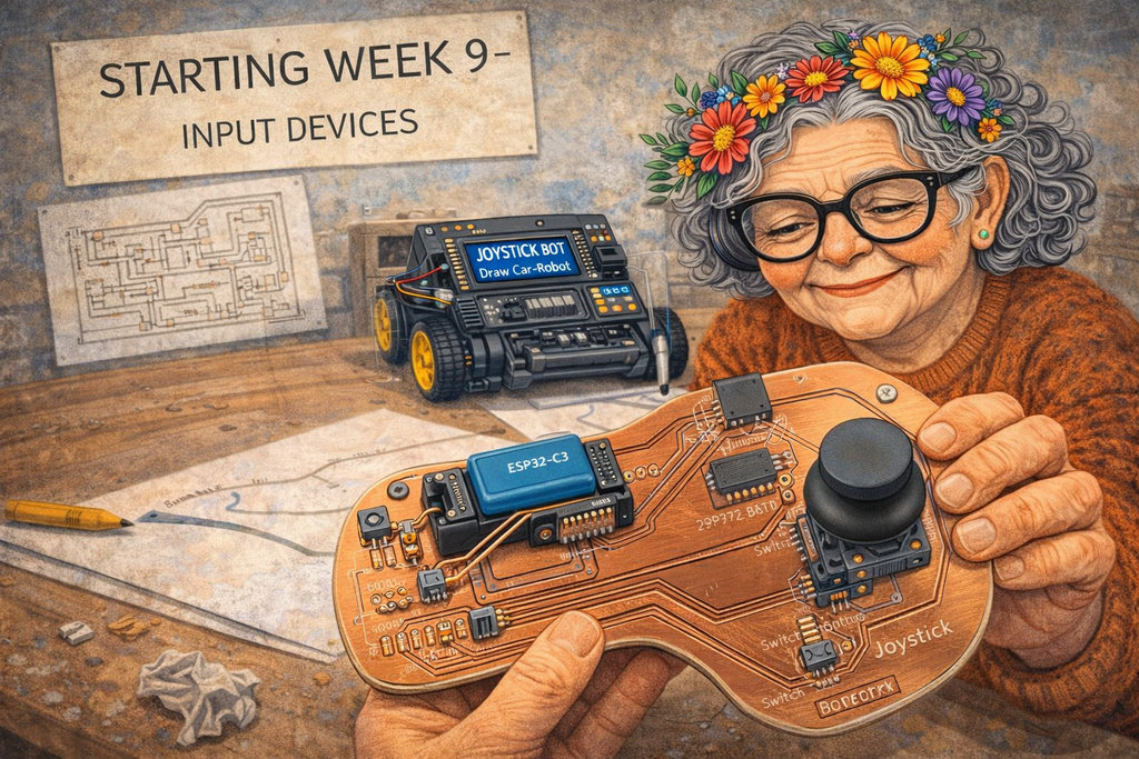
This week I implemented one of the main components of my final project — the joystick 😍
Wireless communication between joystick and car via ESP-NOW protocol,
with OLED display showing live timer, coin count, and battery percentage.
 Output Devices
RC PCB Fixing + Motors Working
DONE
▶
Output Devices
RC PCB Fixing + Motors Working
DONE
▶
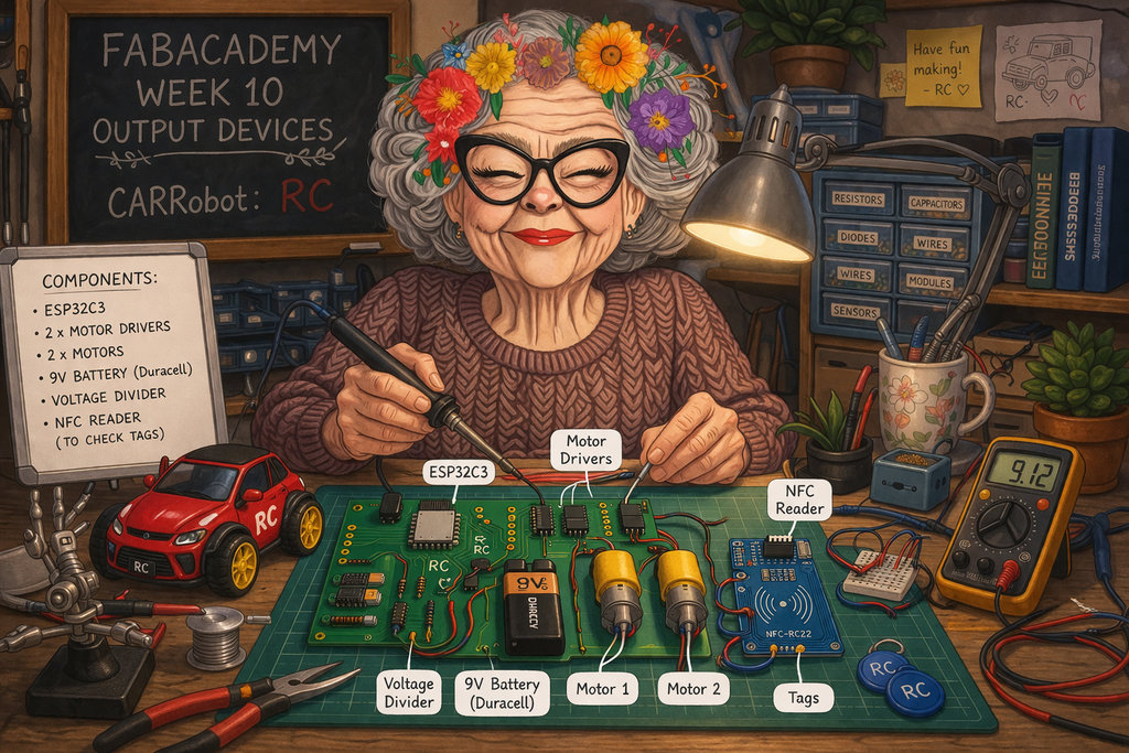
FIX THIS -------------->>>>>>This week I implemented one of the main components of my final project — the joystick 😍
Wireless communication between joystick and car via ESP-NOW protocol,
with OLED display showing live timer, coin count, and battery percentage.
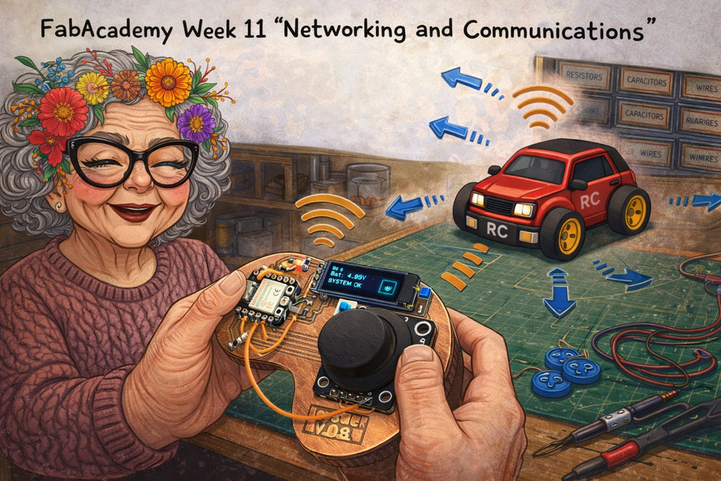 Networking and Communications
RC WiFi + Web Speed Control
DONE
▶
Networking and Communications
RC WiFi + Web Speed Control
DONE
▶
This week I connected my RC car to WiFi and built a
simple web interface to control the motor speed using a
slider. The ESP32 hosted its own web server — visiting the IP
in a browser sent real-time PWM values to the A4953 motor drivers,
which was really satisfying to see working 🎉
The painful part? I accidentally uploaded the RC code into my
joystick and burned my second ESP32-C3 💀
Also learned the hard way why hardware protection matters —
adding 100Ω resistors on output pins can save your board from
a short circuit. Waiting for Joystick v2 😄
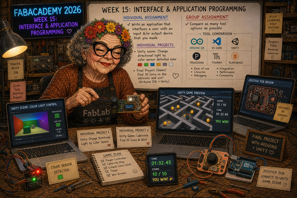 Interface and Application Programming
Unity Game — Digital Final Project Prototype 🌲
DONE
▶
Interface and Application Programming
Unity Game — Digital Final Project Prototype 🌲
DONE
▶
This week I built a Unity simulation of my final project —
a virtual version of the Maze of Birds game where a car
navigates a forest maze and collects 10 coins
before time runs out 🌲
The best part? My real handmade joystick controls the
Unity car via WiFi UDP in real time — and Unity sends back
coin count, timer, WIN, and
GAME OVER signals directly to the OLED display
on the joystick. Two-way communication between hardware and game 🎮
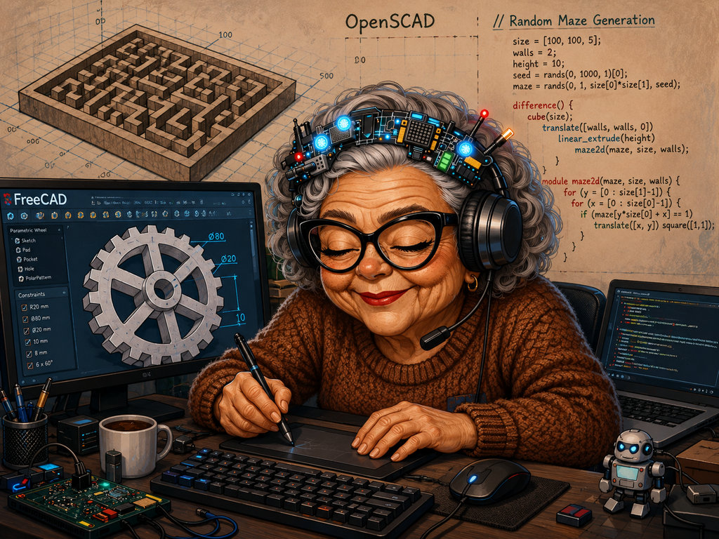
Grandma Manuela also made it into the game — she appears on the
Win and Game Over panels, judging the player's
performance 😄 This week was basically a digital prototype of everything
I was building physically throughout the whole semester.
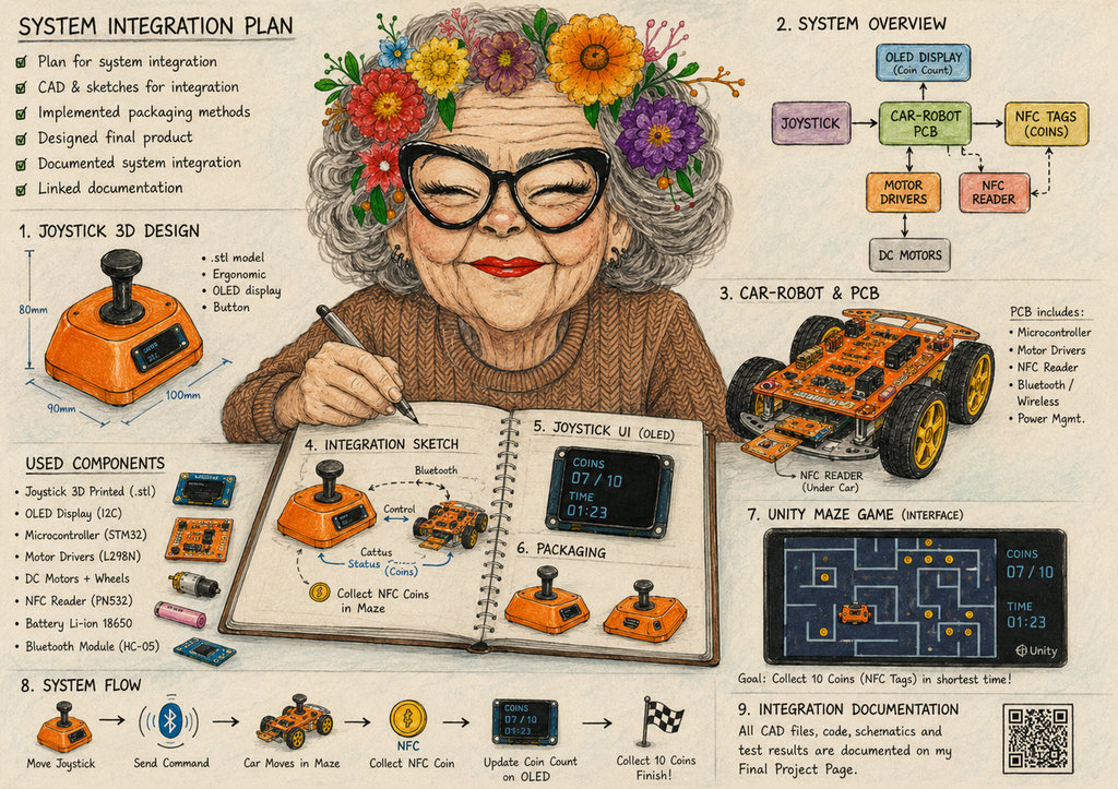 System Integration
Car And Joystick Design
DONE
▶
System Integration
Car And Joystick Design
DONE
▶
This week I started making the final decisions about the design of my robot car and joystick.
Let's start with the joystick.
I designed it in Blender. From the beginning, I knew that Blender was not the most suitable tool for parametric or highly precise CAD modeling, and I only had one day of experience using Blender. 😄
After watching a few tutorial videos, I started working.
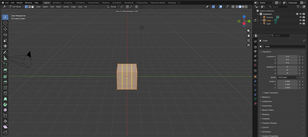
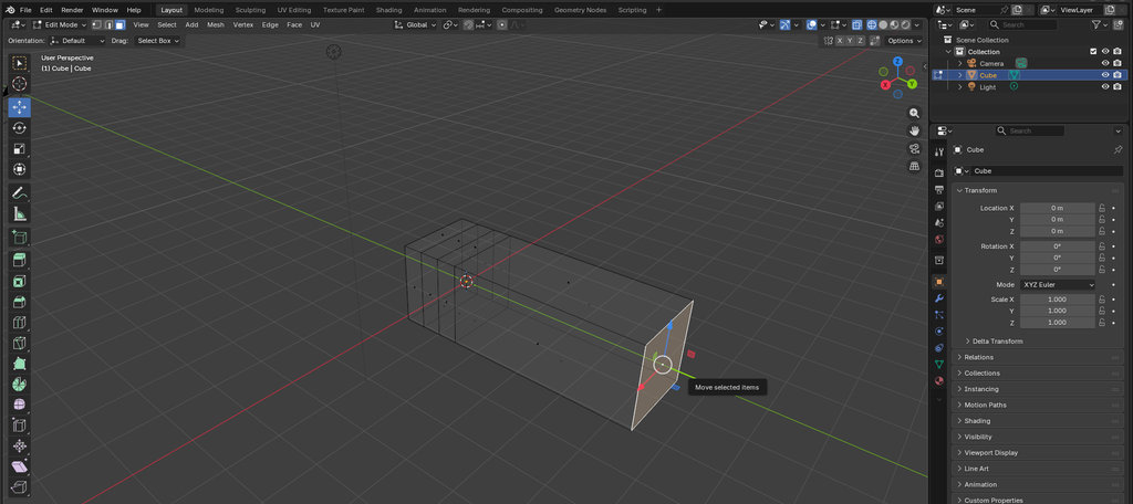
When creating a new Blender project, we first see a cube. By selecting the cube and switching to Edit Mode, I created three additional edge loops on the cube and obtained the following elongated rectangular shape.
If you want to see these Blender operations in more detail, you can check my Week 2 documentation.
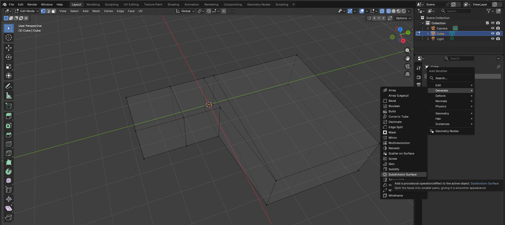
Next, to transform the joystick from a simple square shape into a smoother design, I selected Add Modifier → Generate → Subdivision Surface. To make the surface even smoother, I increased the Viewport Levels value until I achieved the desired curvature.
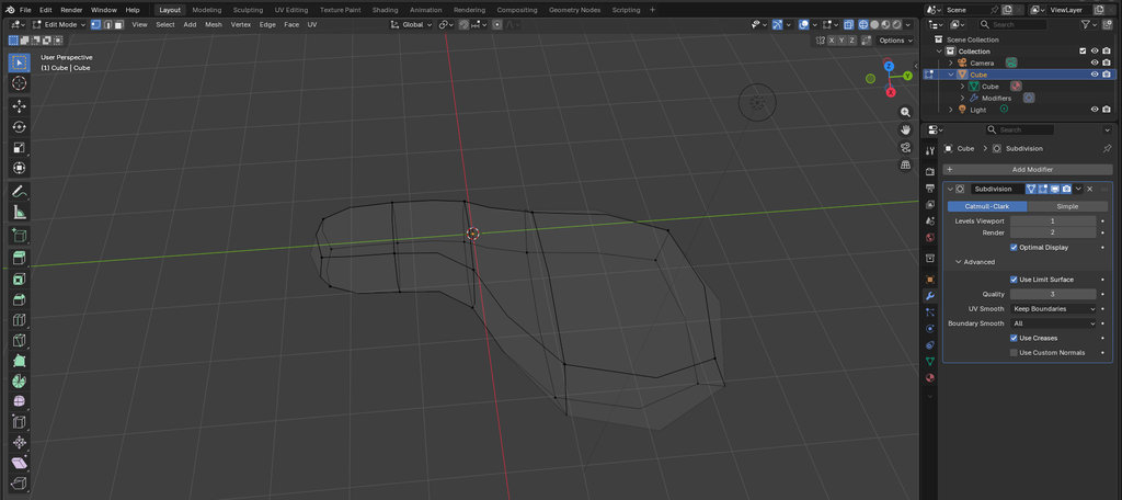
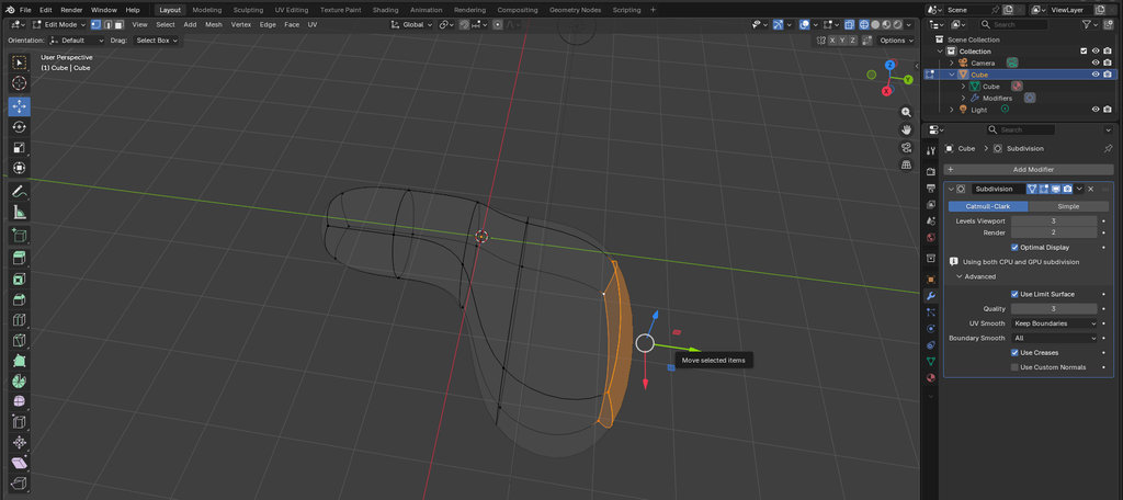
Then, by selecting the appropriate faces, I could move them and create the design I wanted.
As I mentioned before, creating accurate parametric models directly in Blender is quite difficult, so to make sure my joystick matched the exact dimensions I wanted, I exported the 3D model of my PCB from KiCad and imported it into Blender. Here is the top view.
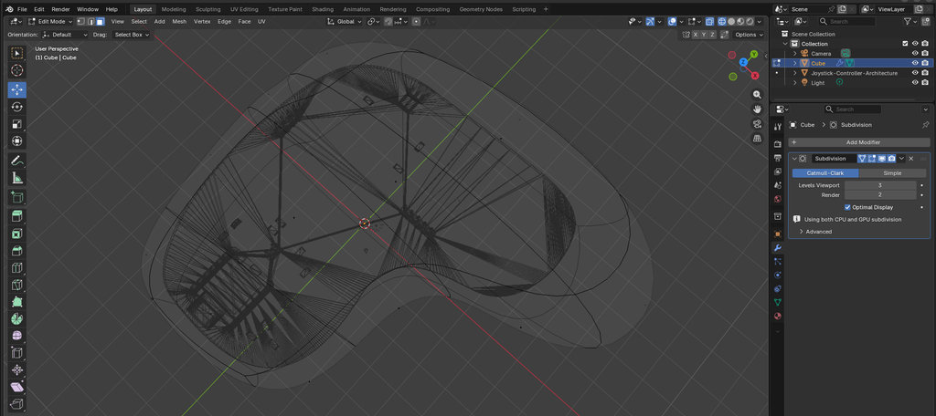
Now I needed to hollow out the joystick so I could create an internal structure to securely hold the PCB.
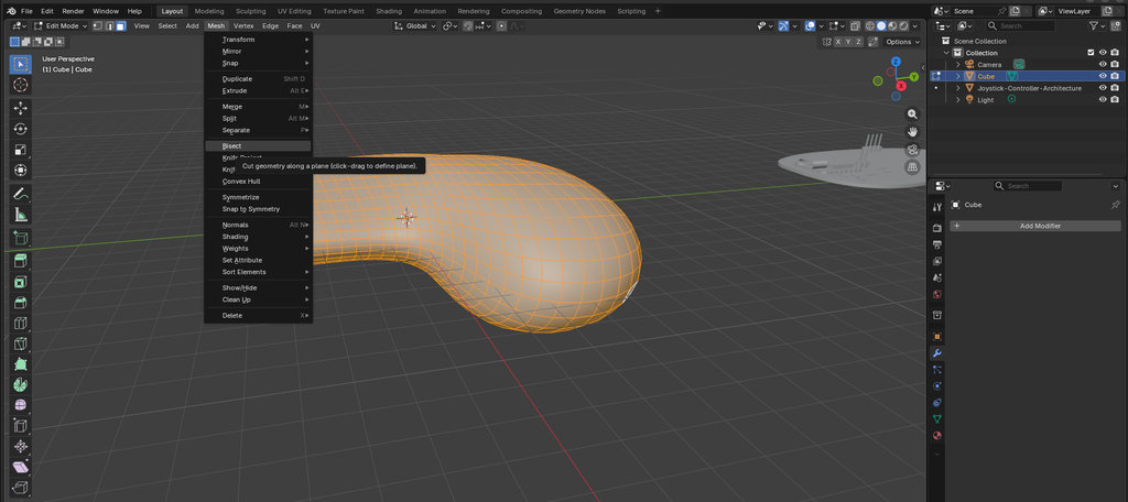
First, I pressed A to select the entire body. Then I selected Mesh → Bisect. After clicking and dragging across the model, Blender split the mesh with an invisible plane.
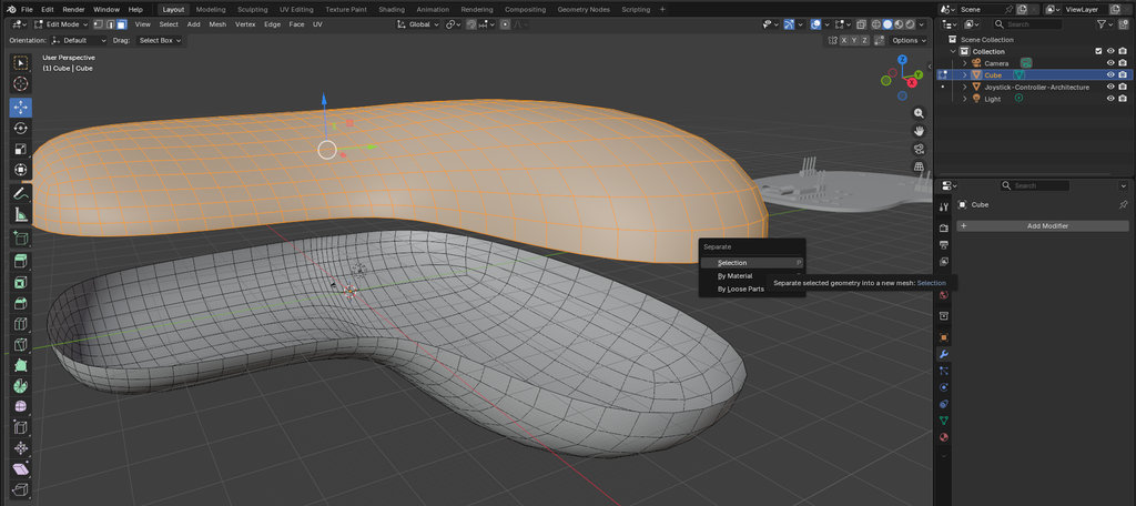
Next, I selected only the upper part of the cut, pressed P, and chose Selection so it became a separate object that I could edit independently.
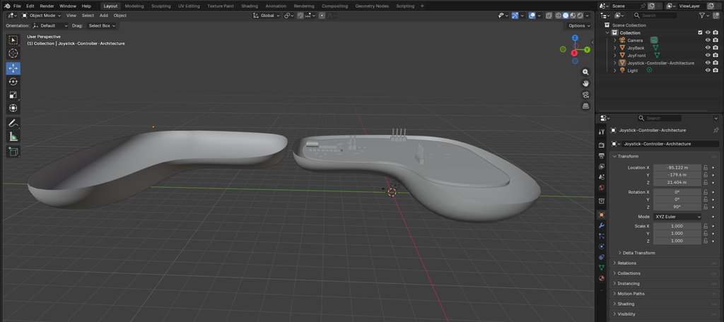
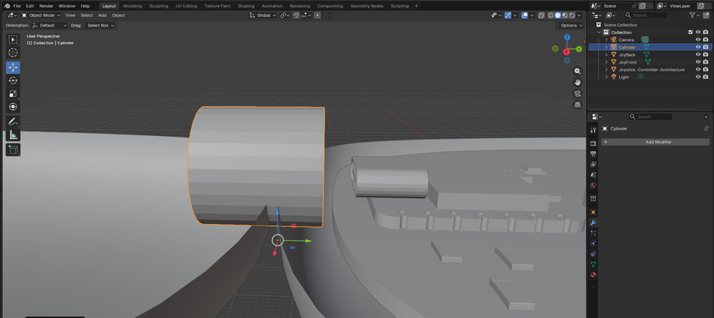
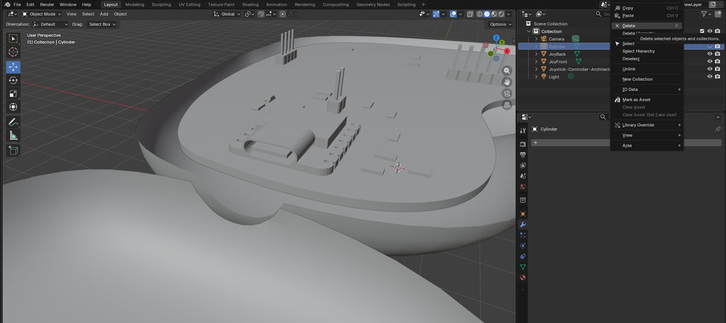
After that, I created an opening so I could easily access the PCB chip while the joystick case was closed. To do this, I created a cylinder, positioned and scaled it as needed, then selected the main object and used Add Modifier → Generate → Boolean. From the Object field, I selected the cylinder using the eyedropper tool and clicked Apply. You can find a more detailed explanation of this Boolean operation in Week 2.
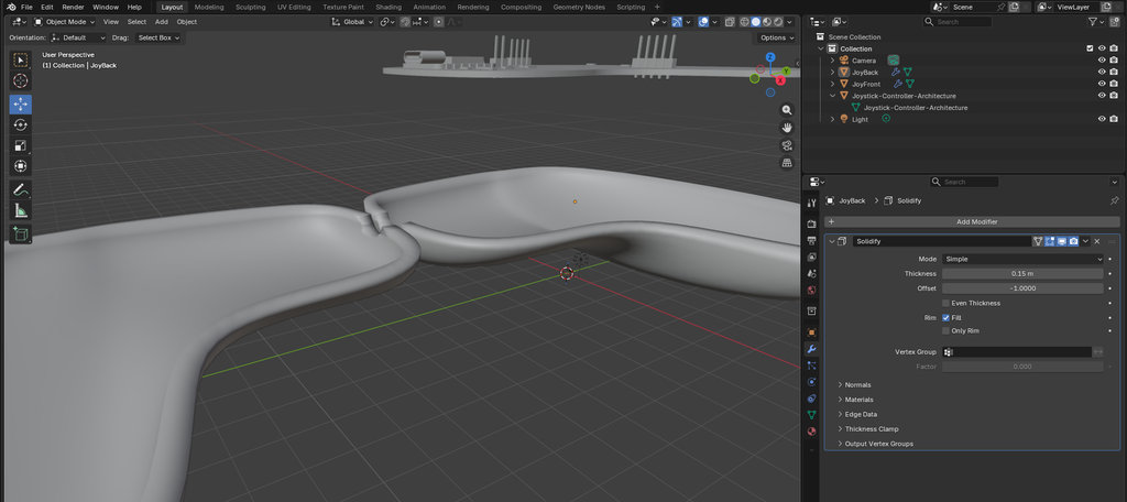
To give the joystick walls some thickness, I selected the main body again and added Add Modifier → Solidify.
I set the Thickness value to 0.15 and the Offset to -1, because I wanted the thickness to be generated toward the inside of the model.
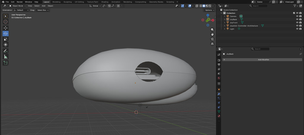
Next, I arranged several thin cubes inside the bottom part of the joystick to support the PCB, while the top cover would hold it in place using small clips.
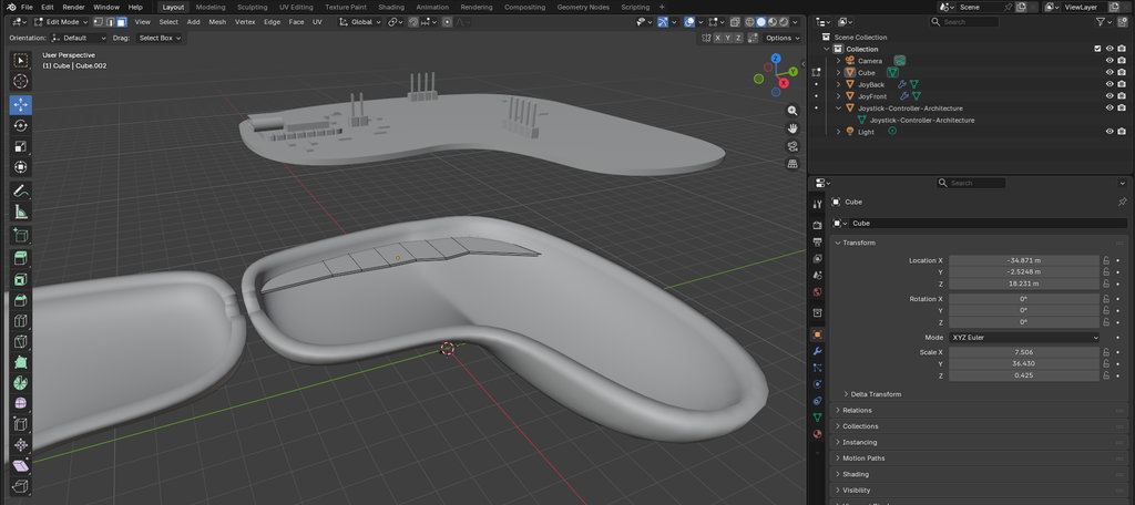
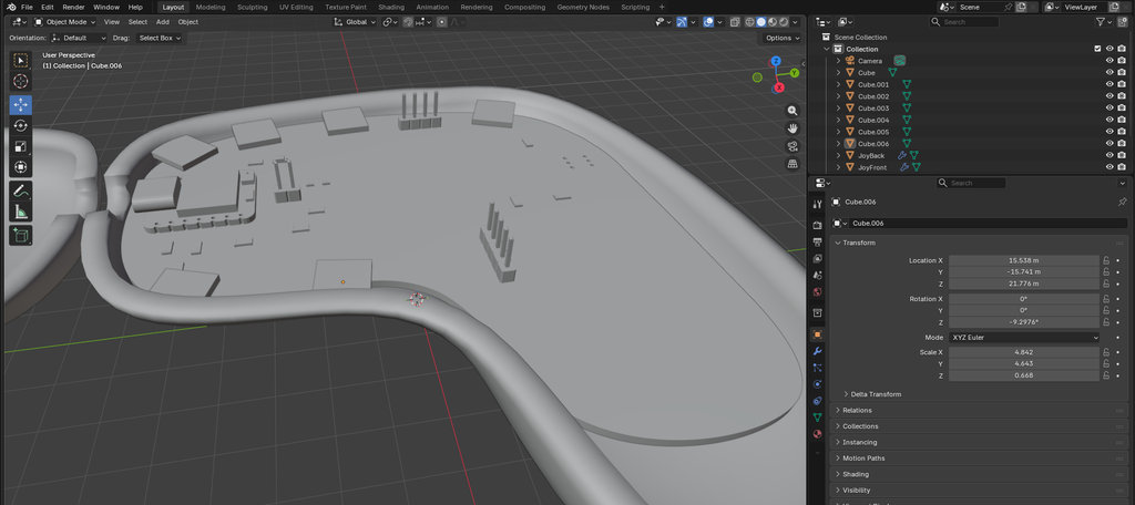
Then I created openings in the top cover for the OLED display, the joystick module, the push button, and the power switch. I created cubes with the correct sizes and positions and removed them from the main body using Boolean operations.
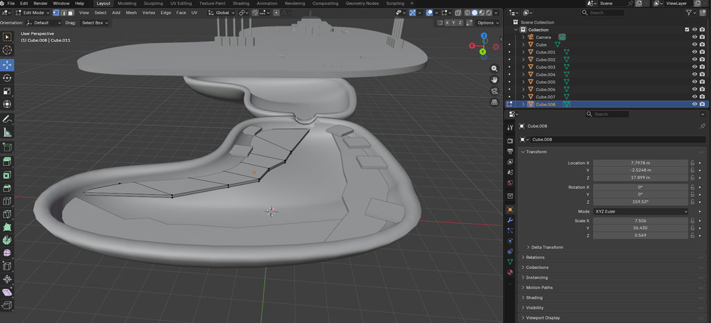
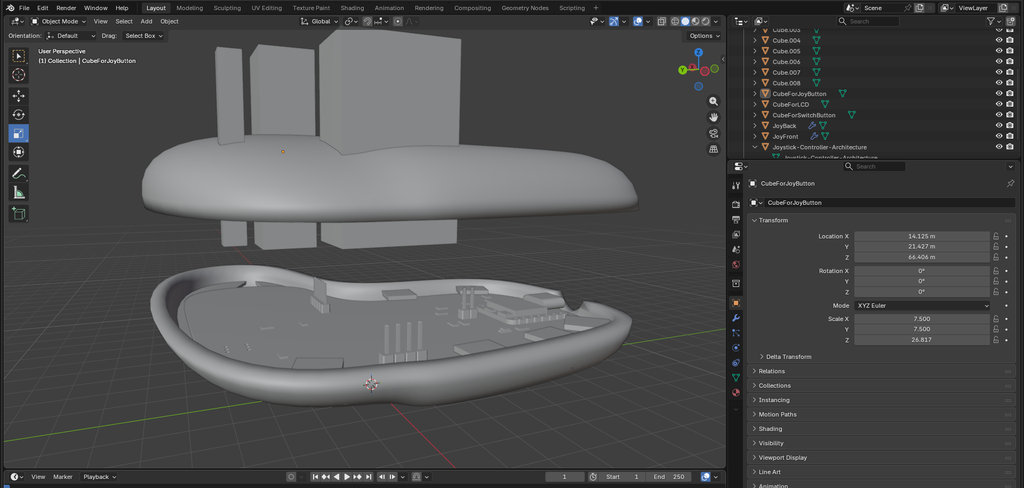
Here is a short Blender video showing the joystick model.
I printed the joystick parts separately on the Elegoo Neptune 4 using PETG filament. The nozzle temperature was 240°C, and the bed temperature was 80°C.
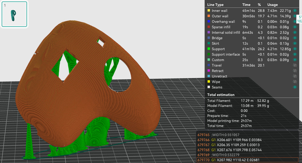
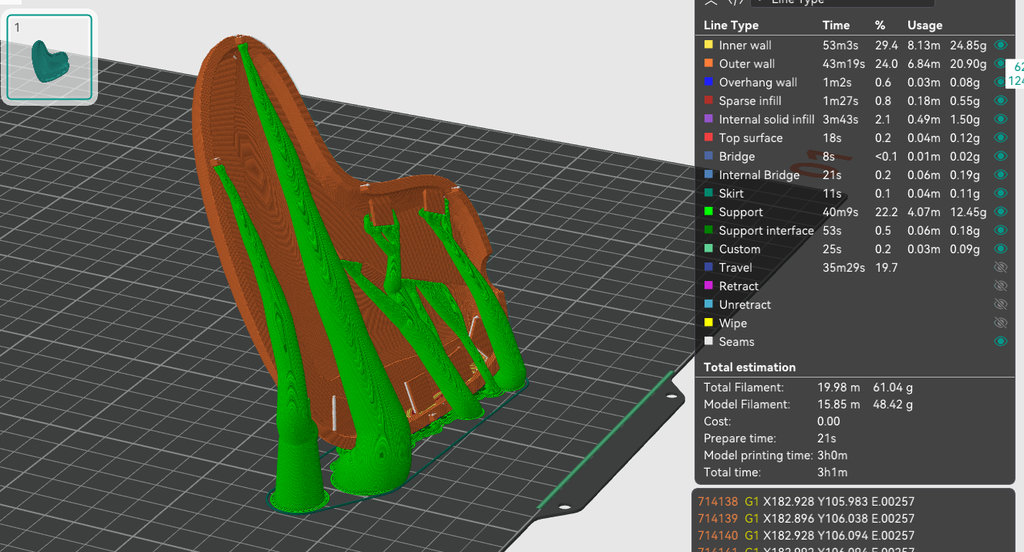
Here is the video of assembling the real printed joystick.
First, I will show the initial prototype that I designed and printed, and then I will move on to the final design.
Now needed to understand how I would design my car and wheels.
I downloaded all the 3D objects in .stl format and imported them into Blender so I could create my car using their real dimensions.
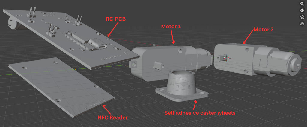
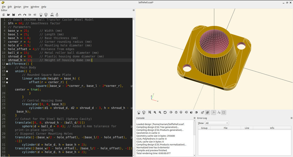
Here are the links where I downloaded all the models from: the motor, battery, button, and for the self-adhesive caster wheel, since I could not find a model online, I quickly generated one in OpenSCAD by asking AI to create code similar to a self-adhesive caster wheel. Then I measured my real wheel and replaced the dimensions in the code. Here is the final result.
// Exact 34x34mm Ball Transfer Caster Wheel Model
$fn = 60; // Smoothness factor
// Parameters
base_w = 25;      // Width (mm)
base_l = 25;      // Length (mm)
base_h = 1.6;     // Base thickness (mm)
corner_r = 4;     // Corner rounding radius (mm)
hole_d = 3.5;     // Mounting hole diameter (mm)
hole_offset = 4;// Distance from edges
ball_d = 15;      // Metal roller ball diameter (mm)
shroud_d = 18;    // Plastic housing dome diameter (mm)
shroud_h = 13;    // Height of housing dome (mm)
difference() {
    // Main Body
    union() {
        // Rounded Square Base Plate
        linear_extrude(height = base_h) {
            offset(r = corner_r) {
                square([base_w - 2*corner_r, base_l - 2*corner_r], center = true);
            }
        }
        // Central Housing Dome
        translate([0, 0, base_h])
            cylinder(d1 = shroud_d, d2 = shroud_d - 3, h = shroud_h - base_h);
    }
    // Cutout for the Steel Ball (Sphere Cavity)
    translate([0, 0, shroud_h - (ball_d/3)])
        sphere(d = ball_d + 0.4); // Added 0.4mm tolerance for print-in-place spacing
    // Diagonal Corner Mounting Holes
    translate([-(base_w/2 - hole_offset), -(base_l/2 - hole_offset), -1])
        cylinder(d = hole_d, h = base_h + 2);
    translate([(base_w/2 - hole_offset), (base_l/2 - hole_offset), -1])
        cylinder(d = hole_d, h = base_h + 2);
}
For the PCB and NFC reader models, I used the 3D model exported from my already finished KiCad PCB project, where I had already integrated the NFC reader model.
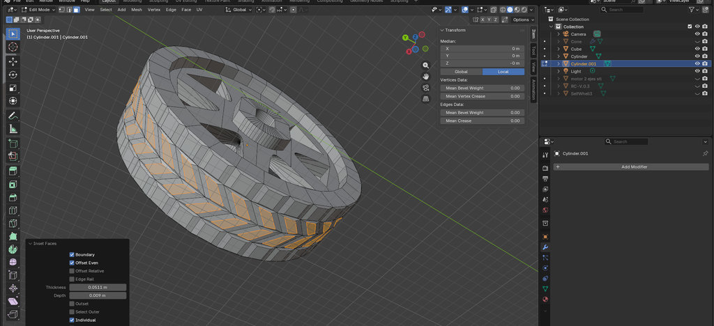
Now let's move to creating the wheel.
Since the wheel needs to directly fit into the motor shaft, I selected the corresponding motor section and entered Edit Mode. Then I selected all the external vertices and captured the shape of the motor connection area.
After that I pressed Shift + D to duplicate it and moved it forward. Then I pressed Ctrl + E and scaled it along the X axis to give it depth so I could subtract it from my cylinder object.
To remove it:
- Switch back to
Object Mode - Select the
cylinderfirst - Open
Modifier - Select
Add Modifier→Generate→Boolean - Use the eyedropper tool and
duplicatedobject - Press
Apply
Now I could see that the shape was removed successfully.
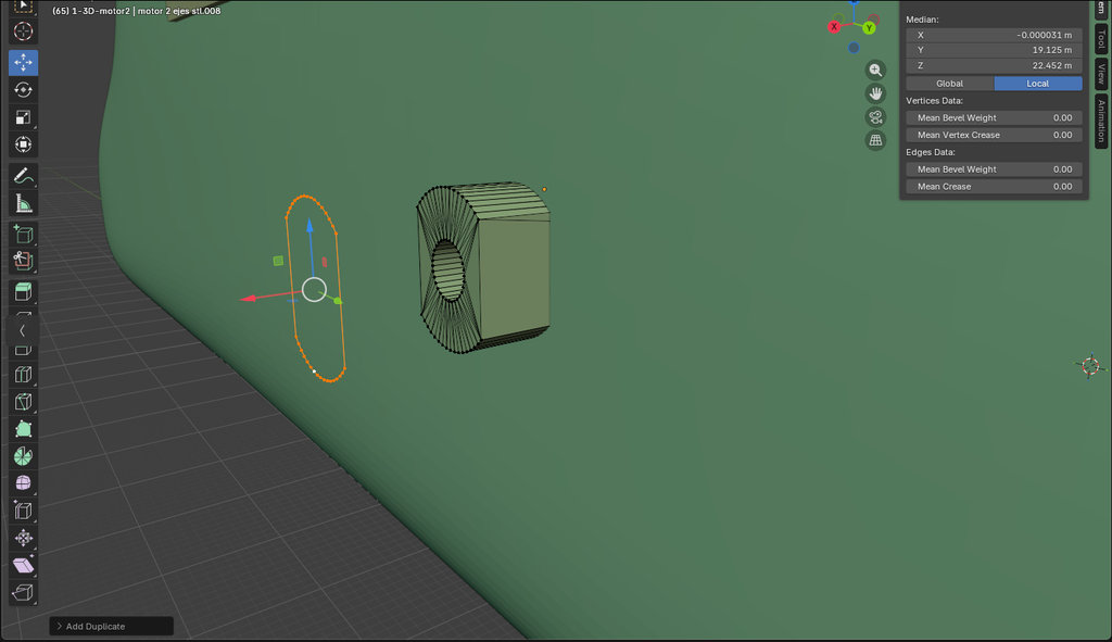
Next, I selected the outer surface of the wheel cylinder and pressed Ctrl + I to invert the selection and isolate the area where I wanted to add depth.
Then I selected the isolated region and pressed: Ctrl + E → move along X axis
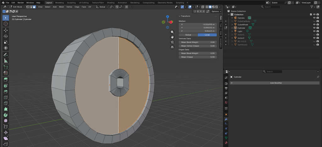
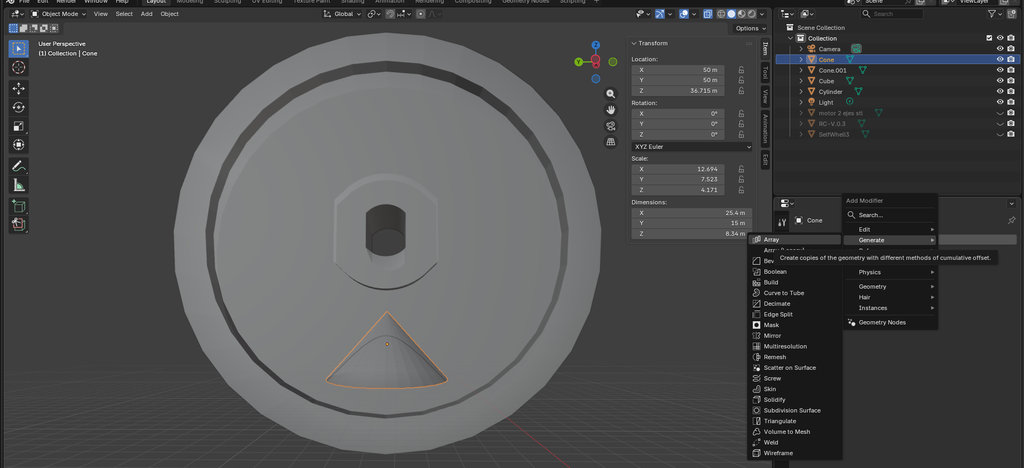
To create holes in the wheel, I selected: Add → Mesh → Cone
I placed the cone where I wanted and duplicated it as many times as needed. Then again I used the Boolean operation to subtract these cones from the main wheel cylinder.
Afterward I selected the curved cone surfaces and modified them using the same process: Ctrl + I → Ctrl + E
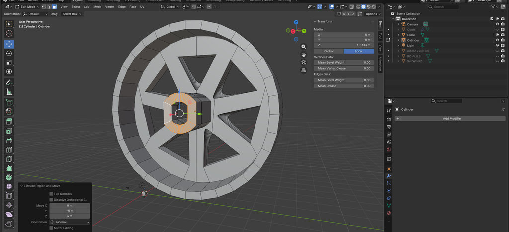
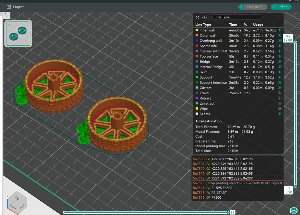
I printed the wheels using the Elegoo Neptune 4 3D printer once again. This time, however, I used PLA filament with a nozzle temperature of 215°C and a bed temperature of 65°C.
Afterwards I exported all required parts as .stl files for printing: File → Export → STL (.stl)
Let's stop here with the wheel section and move to designing the main body.
First, I will show the initial prototype that I designed and printed, and then I will move on to the final design.
And here are all the components that need to fit inside and the printed models.
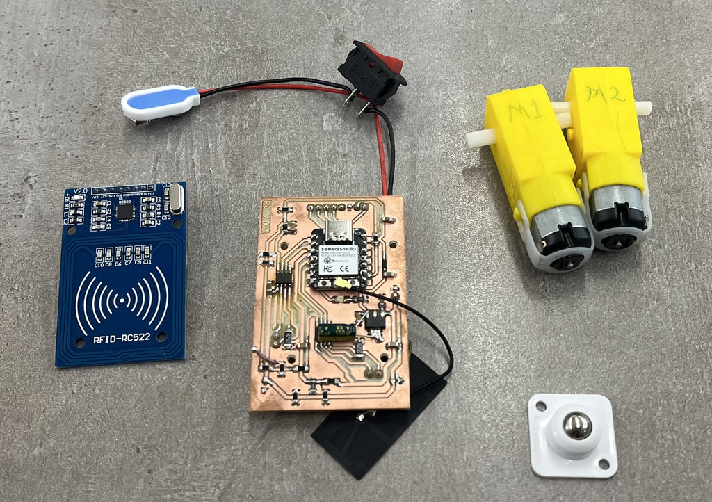
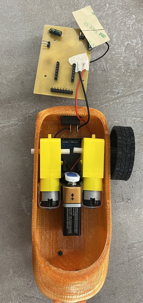
I placed all components inside and checked the fitting — it looked like everything fit properly.
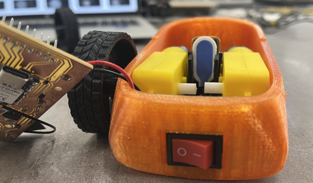
After seeing the design mistakes I had made, I also realized that with my original motors I was wasting too much space inside the car. In addition, a 9V Duracell battery was not powerful enough to drive the robot because the two motors required at least 11–12V. I confirmed this by testing different voltages with a power supply.
Because of this, I decided to change the battery system and use three 4.2V lithium-ion batteries instead. These batteries were also much more convenient because they could be recharged with a charger when they ran out of power.
I also replaced the motors with DC 12V 500RPM N20 High Torque Speed Reduction Motors with Metal Gearboxes. Their smaller size made it much easier to fit both the three batteries and the motors inside the car.
As a result, I redesigned the entire robot.
Once again, I downloaded the 3D models of all the components that would be installed inside the car.
I can say that working this way in Blender became much faster and much easier. 😄
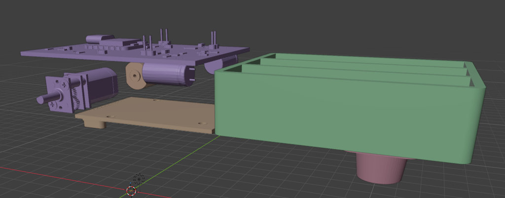
Next, I created a panel that would hold the motors, while the NFC reader would be mounted underneath it. A second panel would then be attached to the first one, and the PCB would be mounted on top of it.
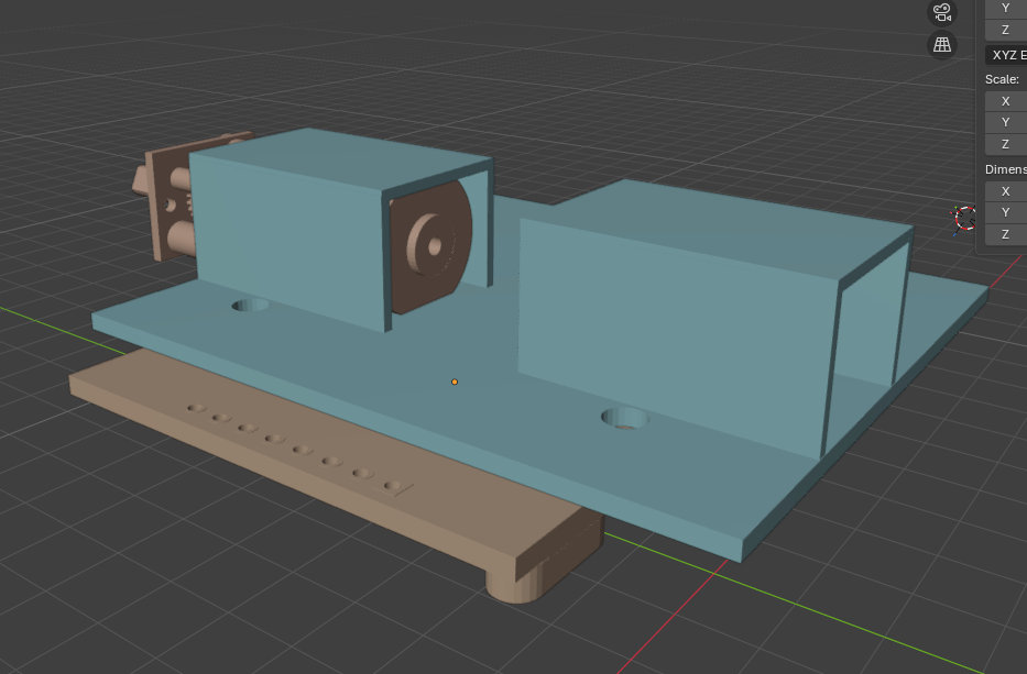
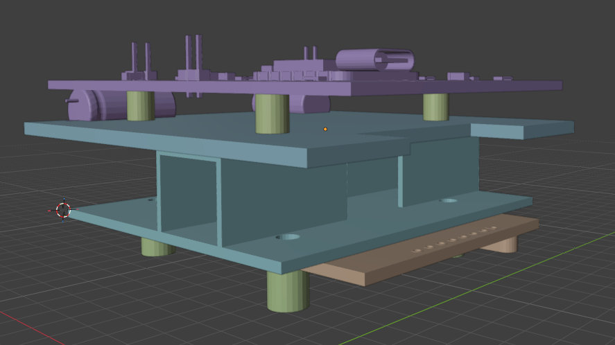
After that, I created the new design of the robot car, once again starting from a single cube.
Taking into account the issues I found in the previous version, I enlarged the joint openings from the outside to make assembly easier, and that was all I needed to change.
Then, using the dimensions taken directly from the imported 3D models of each component, I created and removed all the required openings from the main body using Boolean operations.
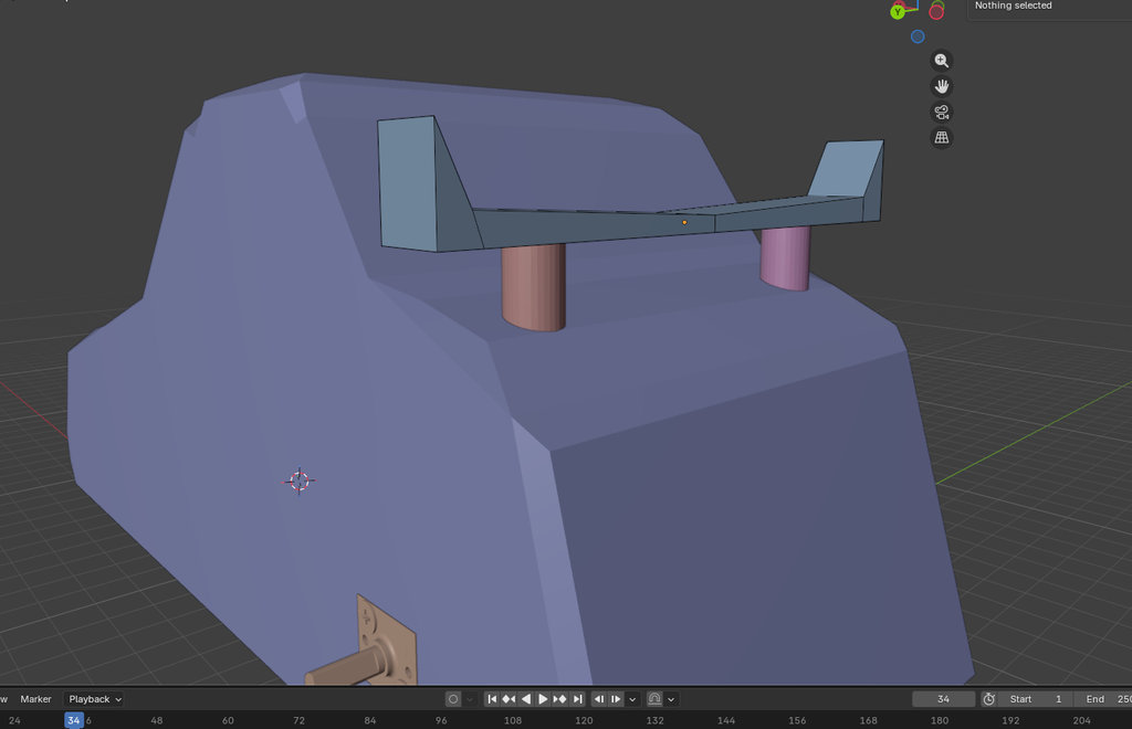
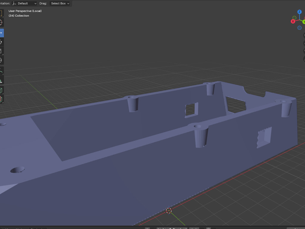
Here is a short video from Blender showing the final design process.
For the first time, the joystick and car existed as real, finished
physical objects — not just breadboards and loose wires. A big milestone
for the Maze of Birds game 🎮
 Wildcard Week
ESP-NOW Code — Car & Joystick Connected
DONE
▶
Wildcard Week
ESP-NOW Code — Car & Joystick Connected
DONE
▶
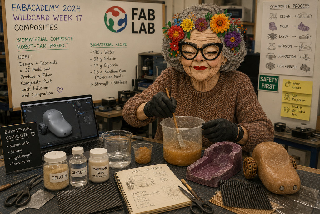
Since I finished this week's assignment quite quickly, I decided to move on to programming the robot car and the joystick so I could finally connect them together.
With the help of my good friend Claude's programming knowledge 😄, I asked him to generate the code for both the joystick and the robot car so that the two ESP32-C3 boards on the PCBs could communicate with each other.
Here is the code he generated for the joystick. I modified several parameters and also corrected the pin assignments.
#include <esp_now.h>
#include <WiFi.h>
#include <Wire.h>
#include <Adafruit_SSD1306.h>

// ── Car fixed MAC ─────────────────────────────────────────────
uint8_t carMAC[] = {0x36, 0x33, 0x33, 0x33, 0x33, 0x33};

// ── Pin Definitions ───────────────────────────────────────────
#define PIN_VRX    2
#define PIN_VRY    3
#define PIN_BATT   4
#define PIN_SW     5
#define PIN_SDA    6
#define PIN_SCL    7
#define PIN_POWER  21
#define PIN_LED    10

// ── OLED ──────────────────────────────────────────────────────
#define SCREEN_W 128
#define SCREEN_H 64
Adafruit_SSD1306 display(SCREEN_W, SCREEN_H, &Wire, -1);

// ── Game config ───────────────────────────────────────────────
#define TOTAL_COINS 5

// ── Joystick Calibration Constants ────────────────────────────
#define JOY_CENTER 2048    // Center position of a 12-bit ADC
#define JOY_DEADZONE 500   // Increase this value to require MORE physical stick movement

// ── Payloads ──────────────────────────────────────────────────
typedef struct {
  int   vrx;
  int   vry;
  bool  sw;
  float battPct;
} JoyData;

typedef struct {
  int           coins;
  int           timeLeft;
  bool          coinJustCollected;
  bool          win;
  bool          gameover;
  bool          waiting;
  unsigned long winTimeMs;
} CarData;

JoyData  joyData;
CarData  carData;
volatile bool newCarData = false;

// ── ESP-NOW callbacks ─────────────────────────────────────────
void onSent(const wifi_tx_info_t *info, esp_now_send_status_t status) { }

void onReceive(const esp_now_recv_info_t *info,
               const uint8_t *data, int len) {
  if (len == sizeof(CarData)) {
    memcpy(&carData, data, sizeof(CarData));
    newCarData = true;
  }
}

// ── Battery percentage ────────────────────────────────────────
float readBattPct() {
  int raw = analogRead(PIN_BATT);
  float voltage = raw * (3.3f / 4095.0f) * 3.0f;
  float pct = (voltage - 6.0f) / (8.4f - 6.0f) * 100.0f;
  return constrain(pct, 0.0f, 100.0f);
}

// ── Draw faces ────────────────────────────────────────────────
void drawSadFace(int cx, int cy) {
  display.drawCircle(cx, cy, 14, SSD1306_WHITE);
  display.fillCircle(cx - 5, cy - 4, 2, SSD1306_WHITE);
  display.fillCircle(cx + 5, cy - 4, 2, SSD1306_WHITE);
  for (int x = -6; x <= 6; x++) {
    int y = cy + 6 + (x * x) / 8;
    display.drawPixel(cx + x, y, SSD1306_WHITE);
  }
}

void drawHappyFace(int cx, int cy) {
  display.drawCircle(cx, cy, 14, SSD1306_WHITE);
  display.fillCircle(cx - 5, cy - 4, 2, SSD1306_WHITE);
  display.fillCircle(cx + 5, cy - 4, 2, SSD1306_WHITE);
  for (int x = -6; x <= 6; x++) {
    int y = cy + 8 - (x * x) / 8;
    display.drawPixel(cx + x, y, SSD1306_WHITE);
  }
}

// ── OLED screens ──────────────────────────────────────────────
void showWaiting() {
  display.clearDisplay();
  display.setTextSize(1);
  display.setTextColor(SSD1306_WHITE);
  display.setCursor(20, 5);
  display.println("Maze of Birds");

  display.setCursor(10, 17);
  display.setTextSize(2);
  display.println(" Press SW  to start");

  display.setTextColor(SSD1306_BLACK, SSD1306_WHITE);
  display.setTextSize(1);
  display.setCursor(30, 55);
  display.println("  Good luck!  ");
  display.display();
}

void showPlaying(int coins, int timeLeft, float batt) {
  display.clearDisplay();
  display.setTextColor(SSD1306_WHITE);

  // Timer countdown (big)
  display.setTextSize(2);
  display.setCursor(0, 0);
  int m = timeLeft / 60;
  int s = timeLeft % 60;
  display.printf("%02d:%02d", m, s);

  // Coins count
  display.setTextSize(1);
  display.setCursor(80, 4);
  display.printf("C:%d/%d", coins, TOTAL_COINS);

  // Battery
  display.setCursor(80, 16);
  display.printf("B:%.0f%%", batt);

  // Divider
  display.drawLine(0, 25, 128, 25, SSD1306_WHITE);

  // Coin icons
  display.setCursor(5, 30);
  display.setTextSize(1);
  display.print("Coins:");
  for (int i = 0; i < TOTAL_COINS; i++) {
    int x = 12 + i * 24;
    int y = 42;
    if (i < coins) {
      display.fillCircle(x, y+6, 9, SSD1306_WHITE);
      display.setTextColor(SSD1306_BLACK);
      display.setCursor(x - 3, y+3);
      display.print(i + 1);
      display.setTextColor(SSD1306_WHITE);
    } else {
      display.drawCircle(x, y+6, 9, SSD1306_WHITE);
      display.setCursor(x - 3, y+3);
      display.print(i + 1);
    }
  }

  display.display();
}

void showGameOver(int coins) {
  display.clearDisplay();
  display.setTextColor(SSD1306_WHITE);
  drawSadFace(108, 22);
  display.setTextSize(1);
  display.setCursor(0, 0);
  display.println("GAME OVER :(");
  display.drawLine(0, 12, 90, 12, SSD1306_WHITE);
  display.setCursor(0, 18);
  display.printf("Coins: %d/%d", coins, TOTAL_COINS);
  display.setCursor(0, 32);
  display.println("Better luck");
  display.println("next time!");
  display.setCursor(0, 52);
  display.println("SW = restart");
  display.display();
}

void showWin(unsigned long winMs, int coins) {
  display.clearDisplay();
  display.setTextColor(SSD1306_WHITE);
  drawHappyFace(108, 22);
  display.setTextSize(1);
  display.setCursor(0, 0);
  display.println("YOU WON! :)");
  display.drawLine(0, 12, 90, 12, SSD1306_WHITE);
  display.setCursor(0, 18);
  int m  = (winMs / 1000) / 60;
  int s  = (winMs / 1000) % 60;
  int ms = (winMs % 1000) / 10;
  display.printf("Time:%02d:%02d.%02d", m, s, ms);
  display.setCursor(0, 32);
  display.printf("All %d coins!", coins);
  display.setCursor(0, 46);
  display.println("Congratulations!");
  display.setCursor(0, 56);
  display.println("SW = play again");
  display.display();
}

void setup() {
  Serial.begin(115200);

  pinMode(PIN_BATT, INPUT);
  pinMode(PIN_SW,    INPUT_PULLUP);
  pinMode(PIN_POWER, INPUT_PULLUP);
  pinMode(PIN_LED,   OUTPUT);
  digitalWrite(PIN_LED, HIGH);

  Wire.begin(PIN_SDA, PIN_SCL);
  display.begin(SSD1306_SWITCHCAPVCC, 0x3C);
  display.setTextColor(SSD1306_WHITE);
  display.clearDisplay();
  display.setCursor(0, 0);
  display.setTextSize(1);
  display.println("Starting...");
  display.display();

  WiFi.mode(WIFI_STA);
  esp_now_init();
  esp_now_register_send_cb(onSent);
  esp_now_register_recv_cb(onReceive);

  esp_now_peer_info_t peer = {};
  memcpy(peer.peer_addr, carMAC, 6);
  peer.channel = 0;
  peer.encrypt = false;
  esp_now_add_peer(&peer);

  showWaiting();
}

void loop() {
  // ── Power switch ──────────────────────────────────────────
  if (digitalRead(PIN_POWER) == LOW) {
    display.clearDisplay();
    display.display();
    display.ssd1306_command(SSD1306_DISPLAYOFF);
    digitalWrite(PIN_LED, LOW);

    joyData.vrx = 2139; joyData.vry = 2248;
    joyData.sw  = false; joyData.battPct = 0;
    esp_now_send(carMAC, (uint8_t*)&joyData, sizeof(joyData));

    while (digitalRead(PIN_POWER) == LOW) { delay(100); }

    display.ssd1306_command(SSD1306_DISPLAYON);
    digitalWrite(PIN_LED, HIGH);
    showWaiting();
    delay(300);
  }

  // ── Read raw joystick values ──────────────────────────────
  int rawX = analogRead(PIN_VRX);
  int rawY = analogRead(PIN_VRY);

  // ── Apply Deadzone Filter ─────────────────────────────────
  // If the movement is small (inside the deadzone), force it to center
  if (abs(rawX - JOY_CENTER) < JOY_DEADZONE) {
    joyData.vrx = JOY_CENTER;
  } else {
    joyData.vrx = rawX;
  }

  if (abs(rawY - JOY_CENTER) < JOY_DEADZONE) {
    joyData.vry = JOY_CENTER;
  } else {
    joyData.vry = rawY;
  }

  joyData.sw      = (digitalRead(PIN_SW) == LOW);
  joyData.battPct = readBattPct();

  esp_now_send(carMAC, (uint8_t*)&joyData, sizeof(joyData));

  // ── Handle incoming car data ──────────────────────────────
  if (newCarData) {
    newCarData = false;

    if (carData.coinJustCollected) {
      for (int i = 0; i < 3; i++) {
        digitalWrite(PIN_LED, LOW);  delay(150);
        digitalWrite(PIN_LED, HIGH); delay(150);
      }
    }

    if (carData.waiting) {
      showWaiting();
    } else if (carData.win) {
      showWin(carData.winTimeMs, carData.coins);
    } else if (carData.gameover) {
      showGameOver(carData.coins);
    } else {
      showPlaying(carData.coins, carData.timeLeft, joyData.battPct);
    }
  }

  delay(50);
}
And this is the code for the robot car.
#include <esp_now.h>
#include <WiFi.h>
#include <SPI.h>
#include <MFRC522.h>
#include "esp_wifi.h"

// ── Fixed MAC ─────────────────────────────────────────────────
uint8_t fixedMAC[] = {0x36, 0x33, 0x33, 0x33, 0x33, 0x33};

// ── Motor Pins (A4953) ────────────────────────────────────────
#define MOTOR_A_IN1   2
#define MOTOR_A_IN2   3
#define MOTOR_B_IN1   5
#define MOTOR_B_IN2   6

// ── Other Pins ────────────────────────────────────────────────
#define PIN_LED      21

// ── NFC (RC522) ───────────────────────────────────────────────
#define NFC_MOSI     10
#define NFC_MISO      9
#define NFC_RST       8
#define NFC_SCK      20
#define NFC_SS        7

MFRC522 nfc(NFC_SS, NFC_RST);

// ── Joystick calibration ──────────────────────────────────────
#define JOY_CENTER_X  2139
#define JOY_CENTER_Y  2248
#define JOY_DEAD       300
#define JOY_MAX       2048

// ── PWM config ────────────────────────────────────────────────
#define PWM_FREQ      5000
#define PWM_RES          8

// ── Signal watchdog ───────────────────────────────────────────
#define SIGNAL_TIMEOUT_MS 500
unsigned long lastReceiveTime = 0;

// ── Game config ───────────────────────────────────────────────
#define TOTAL_COINS    5
#define GAME_TIME_SEC  180

// ── NFC tag UIDs (7 bytes each) ───────────────────────────────
uint8_t coinTags[TOTAL_COINS][7] = {
  {0x1D, 0x05, 0x99, 0xC5, 0x08, 0x10, 0x80},
  {0x1D, 0x02, 0x99, 0xC5, 0x08, 0x10, 0x80},
  {0x1D, 0x04, 0x99, 0xC5, 0x08, 0x10, 0x80},
  {0x1D, 0xF7, 0x98, 0xC5, 0x08, 0x10, 0x80},
  {0x1D, 0x03, 0x99, 0xC5, 0x08, 0x10, 0x80}
};
bool coinCollected[TOTAL_COINS] = {false};

// ── Game state ────────────────────────────────────────────────
enum GameState { WAITING, PLAYING, WIN, GAMEOVER };
GameState gameState = WAITING;
unsigned long gameStartTime = 0;
int coinsCollected = 0;
unsigned long winTime = 0;

// ── Payloads ──────────────────────────────────────────────────
typedef struct {
  int   vrx;
  int   vry;
  bool  sw;
  float battPct;
} JoyData;

typedef struct {
  int           coins;
  int           timeLeft;
  bool          coinJustCollected;
  bool          win;
  bool          gameover;
  bool          waiting;
  unsigned long winTimeMs;
} CarData;

JoyData rxData;
volatile bool newData = false;
uint8_t joystickMac[6];
bool joystickMacKnown = false;

// ── ESP-NOW receive callback ──────────────────────────────────
void onReceive(const esp_now_recv_info_t *info,
               const uint8_t *data, int len) {
  if (len == sizeof(JoyData)) {
    memcpy(&rxData, data, sizeof(JoyData));
    newData = true;
    lastReceiveTime = millis();

    if (!joystickMacKnown) {
      memcpy(joystickMac, info->src_addr, 6);
      esp_now_peer_info_t peer = {};
      memcpy(peer.peer_addr, joystickMac, 6);
      peer.channel = 0;
      peer.encrypt = false;
      esp_now_add_peer(&peer);
      joystickMacKnown = true;
    }
  }
}

// ── Send state to joystick ────────────────────────────────────
void sendCarData(bool coinJust) {
  if (!joystickMacKnown) return;
  CarData cd;
  int elapsed  = (millis() - gameStartTime) / 1000;
  cd.timeLeft          = max(0, GAME_TIME_SEC - elapsed);
  cd.coins             = coinsCollected;
  cd.coinJustCollected = coinJust;
  cd.win               = (gameState == WIN);
  cd.gameover          = (gameState == GAMEOVER);
  cd.waiting           = (gameState == WAITING);
  cd.winTimeMs         = winTime;
  esp_now_send(joystickMac, (uint8_t*)&cd, sizeof(cd));
}

// ── Motor control ─────────────────────────────────────────────
void setMotorA(int speed) {
  speed = constrain(speed, -255, 255);
  if (speed > 0)      { ledcWrite(MOTOR_A_IN1, speed); ledcWrite(MOTOR_A_IN2, 0);      }
  else if (speed < 0) { ledcWrite(MOTOR_A_IN1, 0);     ledcWrite(MOTOR_A_IN2, -speed); }
  else                { ledcWrite(MOTOR_A_IN1, 0);     ledcWrite(MOTOR_A_IN2, 0);      }
}
void setMotorB(int speed) {
  speed = constrain(speed, -255, 255);
  if (speed > 0)      { ledcWrite(MOTOR_B_IN1, speed); ledcWrite(MOTOR_B_IN2, 0);      }
  else if (speed < 0) { ledcWrite(MOTOR_B_IN1, 0);     ledcWrite(MOTOR_B_IN2, -speed); }
  else                { ledcWrite(MOTOR_B_IN1, 0);     ledcWrite(MOTOR_B_IN2, 0);      }
}
void stopAll() { setMotorA(0); setMotorB(0); }

// ── Tank drive ────────────────────────────────────────────────
void tankDrive(int vrx, int vry) {
  int y = vry - JOY_CENTER_Y;
  int x = vrx - JOY_CENTER_X;
  if (abs(y) < JOY_DEAD) y = 0;
  if (abs(x) < JOY_DEAD) x = 0;
  if (y == 0 && x == 0) { stopAll(); return; }
  int thrust = map(-y, -JOY_MAX, JOY_MAX, -255, 255);
  int turn   = map( x, -JOY_MAX, JOY_MAX, -255, 255);
  setMotorA(constrain(thrust + turn, -255, 255));
  setMotorB(constrain(thrust - turn, -255, 255));
}

// ── Match coin tag ────────────────────────────────────────────
int matchCoin(byte *uid, byte size) {
  if (size != 7) return -1;
  for (int i = 0; i < TOTAL_COINS; i++) {
    if (!coinCollected[i] &&
        memcmp(uid, coinTags[i], 7) == 0) {
      return i;
    }
  }
  return -1;
}

// ── Reset game ────────────────────────────────────────────────
void resetGame() {
  gameState      = PLAYING;
  coinsCollected = 0;
  winTime        = 0;
  gameStartTime  = millis();
  for (int i = 0; i < TOTAL_COINS; i++) coinCollected[i] = false;
  Serial.println("Game started!");
}

void setup() {
  Serial.begin(115200);

  ledcAttach(MOTOR_A_IN1, PWM_FREQ, PWM_RES);
  ledcAttach(MOTOR_A_IN2, PWM_FREQ, PWM_RES);
  ledcAttach(MOTOR_B_IN1, PWM_FREQ, PWM_RES);
  ledcAttach(MOTOR_B_IN2, PWM_FREQ, PWM_RES);
  stopAll();

  pinMode(PIN_LED, OUTPUT);
  digitalWrite(PIN_LED, LOW);

  SPI.begin(NFC_SCK, NFC_MISO, NFC_MOSI, NFC_SS);
  nfc.PCD_Init();

  WiFi.mode(WIFI_STA);
  esp_wifi_set_mac(WIFI_IF_STA, fixedMAC);
  if (esp_now_init() != ESP_OK) return;
  esp_now_register_recv_cb(onReceive);

  lastReceiveTime = millis();
  Serial.println("Car ready. Press SW on joystick to start.");
}

void loop() {
  int elapsed  = (millis() - gameStartTime) / 1000;
  int timeLeft = max(0, GAME_TIME_SEC - elapsed);

  // ── Timer expired ─────────────────────────────────────────
  if (gameState == PLAYING && timeLeft == 0) {
    gameState = GAMEOVER;
    stopAll();
    sendCarData(false);
    Serial.println("Game Over!");
  }

  // ── Signal timeout watchdog ───────────────────────────────
  if (millis() - lastReceiveTime > SIGNAL_TIMEOUT_MS) {
    stopAll();
  }

  // ── Joystick input ────────────────────────────────────────
  if (newData) {
    newData = false;

    // SW button pressed = start or restart game
    if (rxData.sw) {
      resetGame();
      sendCarData(false);
    } else {
      // Only drive during PLAYING state
      if (gameState == PLAYING) {
        tankDrive(rxData.vrx, rxData.vry);
      } else {
        stopAll();
      }
    }
  }

  // ── NFC scan (only while playing) ────────────────────────
  if (gameState == PLAYING &&
      nfc.PICC_IsNewCardPresent() && nfc.PICC_ReadCardSerial()) {

    // ── DELETE this block after testing ──────────────────
    Serial.print("TAG UID: ");
    for (byte i = 0; i < nfc.uid.size; i++) {
      Serial.printf("%02X ", nfc.uid.uidByte[i]);
    }
    Serial.println();
    // ── END delete block ──────────────────────────────────

    int idx = matchCoin(nfc.uid.uidByte, nfc.uid.size);
    if (idx >= 0) {
      coinCollected[idx] = true;
      coinsCollected++;
      Serial.printf("Coin %d collected! Total: %d/%d\n",
                    idx + 1, coinsCollected, TOTAL_COINS);

      // Flash car LED
      for (int i = 0; i < 3; i++) {
        digitalWrite(PIN_LED, HIGH); delay(150);
        digitalWrite(PIN_LED, LOW);  delay(150);
      }

      // Check win
      if (coinsCollected >= TOTAL_COINS) {
        gameState = WIN;
        winTime   = millis() - gameStartTime;
        stopAll();
        Serial.printf("YOU WIN! Time: %lums\n", winTime);
      }

      sendCarData(true);
    }

    nfc.PICC_HaltA();
    nfc.PCD_StopCrypto1();
  }

  // ── Periodic state update to joystick ────────────────────
  static unsigned long lastSend = 0;
  if (millis() - lastSend > 200) {
    lastSend = millis();
    sendCarData(false);
  }
}
At first, after programming both the car and the joystick, everything worked perfectly—but only while the robot car was connected to the computer through a USB cable and receiving power from it. As soon as I disconnected the USB cable, the car stopped responding to the joystick.
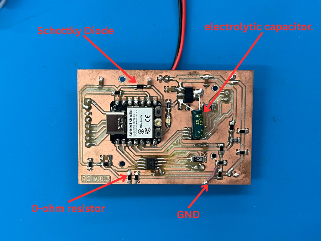
After spending a long time reviewing and testing the code, I realized that the problem was not in the software. As usual, when I reached a dead end, Onik came to the rescue. He noticed that on my robot car PCB, the ESP32-C3's GND was connected to the main GND through two 0Ω resistors.
In reality, the PCB contained many different components, and although I had tried to avoid using 0Ω resistors, I couldn't completely avoid them. This issue helped me understand in practice why it is better to avoid using 0Ω resistors whenever possible.
To solve the problem, I connected the chip's GND directly to the PCB's main GND using a wire.
And finally... we had a working final project. 😄😄
Here is the test video.
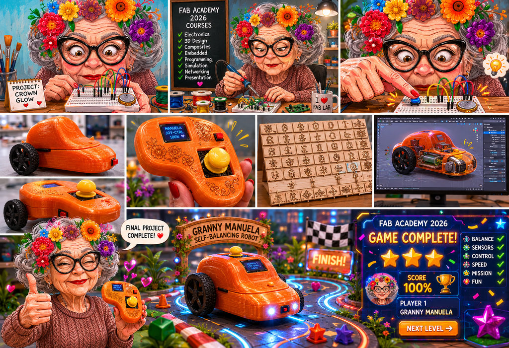 Applications and Implications Project Development
This week also passed very quickly, so I decided to implement an idea that I had been thinking about for a long time.
I really wanted to integrate Armenian elements into my game.
At first, I decided to laser engrave traditional Armenian patterns onto the maze walls.
After doing that, I realized that I wanted to help introduce the Armenian alphabet to more people around the world. So I started engraving the Armenian Bird Letters onto the maze walls. I believe these letters are another important part of our history and culture. If you are interested, you can learn more about them here.
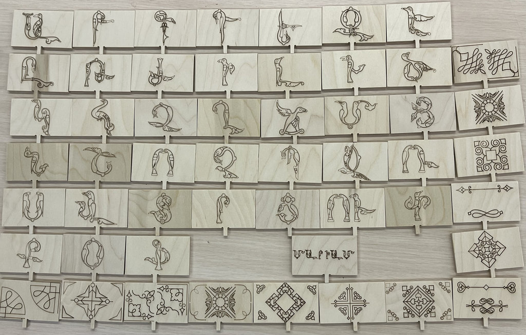
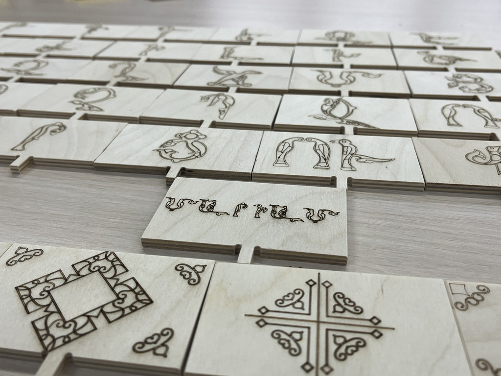
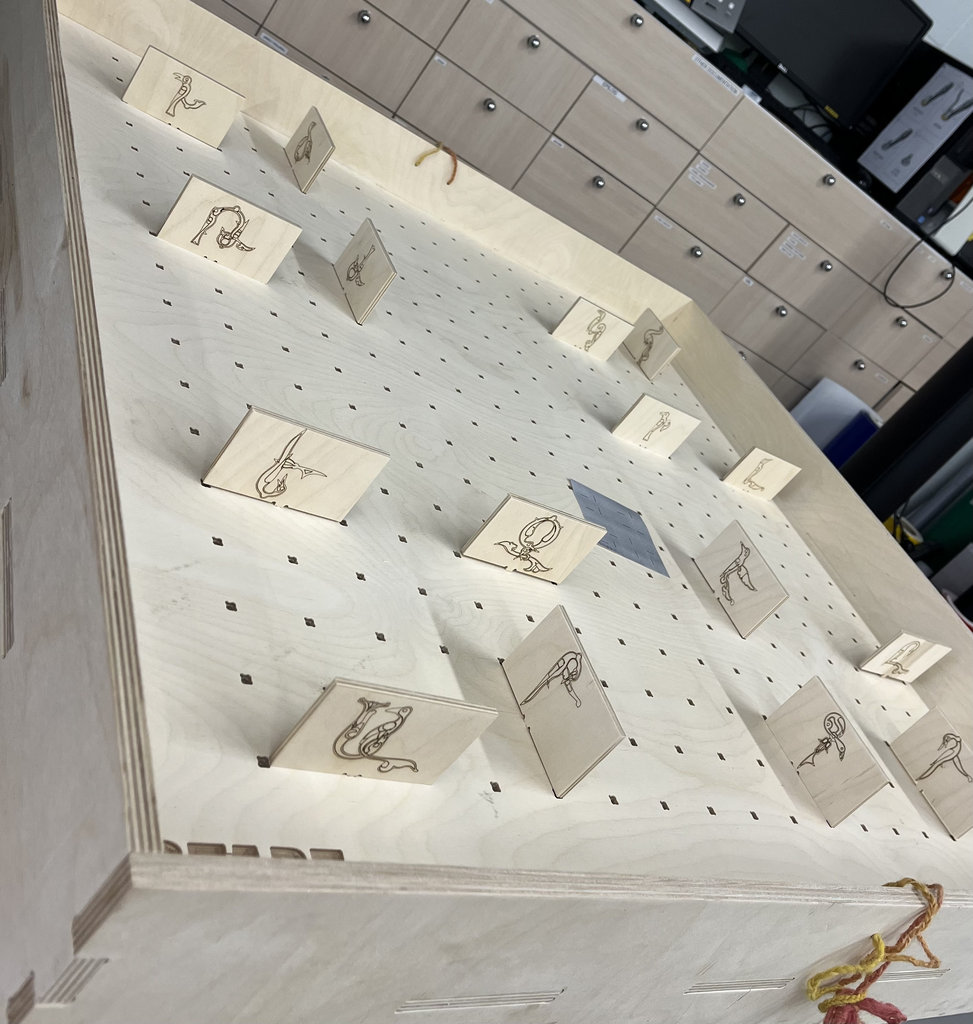
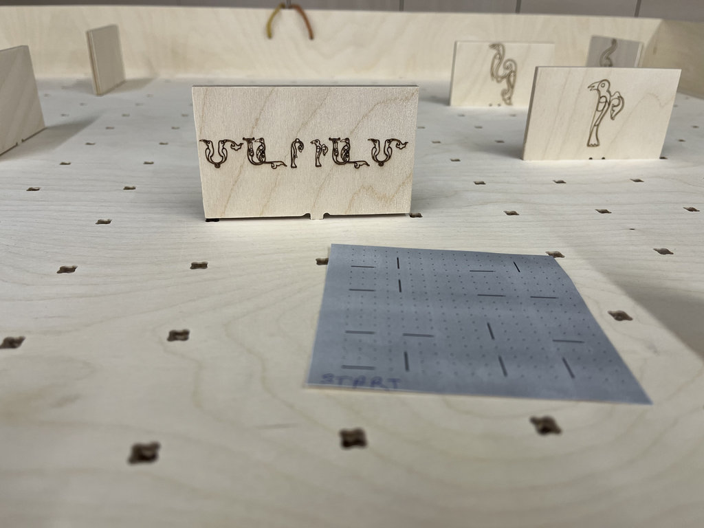
Now I am really proud of what I created. 😄😄
 Invention, Intellectual Property, and Income
Presentation Video — Edited with Shotcut
DONE
▶
Invention, Intellectual Property, and Income
Presentation Video — Edited with Shotcut
DONE
▶
Finally, I would like to mention the video editing software I used to create my final presentation video. I used Shotcut, which is an open-source and very user-friendly video editor. It was my first time editing a video, and I think the result turned out pretty well. 😄
▸ Everything below is what you need to build one Maze of Birds set (1 car + 1 joystick + game board), together with the design files and code above. Prices are approximate — shown in USD and Armenian Dram (AMD), exchange rate used: 1 USD ≈ 370 AMD. Verify against your own receipts before relying on the totals.
| COMPONENT | QTY | UNIT (USD) | UNIT (AMD) | SOURCE | LINE TOTAL (USD) | LINE TOTAL (AMD) |
|---|---|---|---|---|---|---|
| ESP32-C3 SuperMini (car) | 1 | $14.50 | 5,365 | AliExpress | $14.50 | 5,365 |
| ESP32-C3 SuperMini (joystick) | 1 | $14.50 | 5,365 | AliExpress | $14.50 | 5,365 |
| N20 12V 500RPM DC gear motor | 2 | $3.50 | 1,295 | Amazon | $7.00 | 2,590 |
| A4953 H-Bridge motor driver | 2 | $1.20 | 444 | ChipDip.am | $2.40 | 888 |
| MFRC522 RC522 NFC/RFID reader | 1 | $4.43 | 1,639 | Amazon | $4.43 | 1,639 |
| NTAG213 NFC coin stickers | 1 pack (5) | $3.00 | 1,110 | Amazon | $3.00 | 1,110 |
| SSD1306 0.96" OLED display | 1 | $6.50 | 2,405 | Amazon | $6.50 | 2,405 |
| Joystick module (KY-023, X/Y + SW) | 1 | $1.50 | 555 | Amazon | $1.50 | 555 |
| 4.2V Li-ion cell (18650) | 3 | $5.00 | 1,850 | Temu | $15.00 | 5,550 |
| LM2940 5V voltage regulator (SOT-223) | 1 | $0.80 | 296 | Amazon | $0.80 | 296 |
| Schottky diode | 1 | $0.20 | 74 | Amazon | $0.20 | 74 |
| Electrolytic capacitors (10µF/1000µF assortment) | 1 set | $1.00 | 370 | Amazon | $1.00 | 370 |
| Toggle / push button switch | 2 | $0.40 | 148 | Amazon | $0.80 | 296 |
| Status LED (1206 SMD) | 2 | $0.10 | 37 | Amazon | $0.20 | 74 |
| PETG filament (joystick case, ~150g used) | 150g of 500g spool | $10.00 /spool | 3,700 /spool | Amazon | $3.00 | 1,110 |
| PLA filament (wheels, ~80g used) | 80g of 200g spool | $5.50 /spool | 2,035 /spool | Amazon | $2.20 | 814 |
| Playwood board (game maze + walls) | 1 sheet | $10.00 | 3,700 | local supplier | $10.00 | 3,700 |
| Self-adhesive caster wheel (front, 3D printed housing) | 1 | $0.80 | 296 | Amazon | $0.80 | 296 |
| Wires, headers, screws, misc. hardware | 1 set | $2.00 | 740 | local supplier | $2.00 | 740 |
| TOTAL | $89.83 | 33,237 ֏ | ||||
▸ Not included above: 3D printer + filament already owned, laser cutter / CNC machine time (lab-provided), and the Armenian Bird Letters engraving artwork (free, self-designed). This BOM covers only the parts a maker needs to buy to reproduce one Maze of Birds set — combined with the KiCad, OpenSCAD, Blender, and Arduino files in the Downloads section below, that should be everything needed to recreate the project.
▸ Filament lines show the full spool price (as bought) plus the actual line cost prorated to the grams used for this project.
This project is licensed under the Creative Commons CC BY-NC-SA 4.0 license.
Maze of Birds
© 2026 by
Mariam Daghbashyan
is licensed under
CC BY-NC-SA 4.0


I chose this license to allow others to learn from, remix, and build upon this project for non-commercial purposes, provided they give appropriate credit and share their work under the same license.