
Week 11

AI prompt:
Now need to create an image for FabAcademy week 11 'Networking and Communications'. This week, she wants to control RC with her designed Joystick. Need to only Drive Motors, and with the joystick set the direction to RC
Networking and Communications
For this week's group assignment, Hrach and I needed a reliable, low-latency way to link my physical Joystick to his Drone Parachute Case.
We chose MQTT over standard HTTP for four main reasons:
- Decoupled Architecture:
- Near-Zero Latency:
- Auto-Reconnection:
- Lightweight for Hardware:
My joystick doesn't need to know Hrach’s ESP32-C3 IP address. It just publishes to the broker, and his board listens.
MQTT has a tiny 2-byte header compared to heavy HTTP headers. This ensures the parachute deploys instantly when the button is pressed.
Drones move and lose signal. MQTT uses a Keep-Alive heartbeat and our MAC-based reconnect() function to instantly recover dropped connections.
The asynchronous callback() setup leaves the CPU free to handle the high-precision PWM timing required by the ESP32Servo library.
Here is the video demonstration of our work. You can find the remaining details on our Group Assignment page.
Finally, the week has come when I connect my RC and joystick together 🤩
Even though the NFC reader on the RC is not working right now, I still decided to move forward and try to control the motors using the joystick.
JOYSTICK WiFi connection
To fully understand the system, I approached it step by step.
First, I connected my joystick to WiFi and displayed the IP address on the I2C LCD.
Here are the parts of the code I added to my main joystick code (the full code is in Week 9 documentation).
The I2C LCD communicates through I2C using address 0x3C.
After making several modifications to the pin assignments and logic conditions, I achieved the final result.
Add Library and Credentials
#include <WiFi.h>

const char* ssid = "iPhonw";
const char* password = "Manuela20";
Initialize the Wi-Fi connection. Added this right before startAnimation();.
void setup() {
  // ... my existing pinMode and Wire code ...

  WiFi.begin(ssid, password); // Start connecting in the background

  startAnimation();
  analogReadResolution(12);
}
In my "DISPLAY TEXT" section, added this logic to show the Wi-Fi status at the bottom of the screen (around Y-coordinate 25).
 // --- WIFI STATUS (Bottom Left) ---
  display.setCursor(0, 25);
  if (WiFi.status() == WL_CONNECTED) {
    display.print("WiFi: ON ");
    // Optional: show IP or Signal Strength
    // display.print(WiFi.RSSI());
  } else {
    display.print("WiFi: OFF");
  }

  // --- ALERT SYSTEM (Shifted slightly or combined) ---
  if(batV < 3.4 && batV > 1.0) {
     display.setCursor(60, 25); // Move Low Bat alert to the right
     display.print("! LOW !");
  }
Here is the status displayed on the LCD.
The I2C LCD in this case is not just a simple screen — it works as a communication node on a shared network.
It is a classic example of primary-secondary communication:
instead of the microcontroller using many pins to control everything directly, it uses only 2 wires (SDA and SCL) to send data.
The I2C bus did not require additional external pull-up resistors because the LCD module already includes pull-up resistors on the SDA and SCL lines. Therefore, the ESP32-C3 could communicate with the display directly through the I2C bus.
So basically, instead of micromanaging every detail, the controller sends high-level data, and the LCD handles the rest.
After that, the next step was to connect the joystick and PC to the same WiFi network.
This means I can read joystick movement data directly in the PC terminal.
To get the PC IP address, I used:
ipconfighostname -i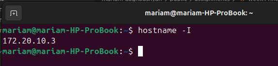
Then I added these code parts into my main program.
Added the WiFiUdp.h library and send a formatted string containing my X and Y values
#include <WiFiUdp.h>

WiFiUDP udp;
const char* pc_ip = "172.20.10.3"; // my PC IP address
const int udp_port = 4210;
Added this inside my loop() (after calculate xRaw and yRaw):
  // --- SEND DATA TO PC ---
  if (WiFi.status() == WL_CONNECTED) {
    udp.beginPacket(pc_ip, udp_port);
    String data = String(xRaw) + "," + String(yRaw);
    udp.print(data);
    udp.endPacket();
  }
I used this simple Python script to "listen" for the joystick data and print it to my screen.
import socket

# Listen on all available interfaces at port 4210
UDP_IP = "0.0.0.0"
UDP_PORT = 4210

sock = socket.socket(socket.AF_INET, socket.SOCK_DGRAM)
sock.bind((UDP_IP, UDP_PORT))

print(f"Listening for Joystick data on port {UDP_PORT}...")

while True:
    data, addr = sock.recvfrom(1024) # buffer size is 1024 bytes
    print(f"Joystick Position (X,Y): {data.decode('utf-8')}")
For reading the data, I ran this Python script in the Visual Studio Code terminal:
python3 read_joystick.py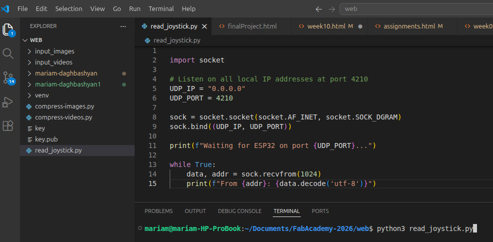
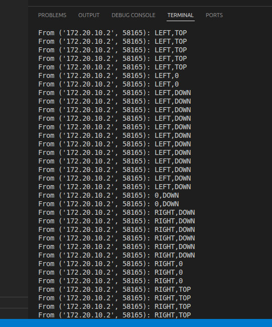
And here is the result.
After that, it was time to program the RC to connect to the same WiFi…
But of course… something had to go wrong 😵💫
Somehow, I accidentally uploaded the RC code into my joystick 😭
And yes… this resulted in burning my second ESP32-C3 💀

AI prompt:
“Change this crying girl's face to a grandmother's face when she is also crying.”
While I was emotionally processing my joystick’s “death” 😄, Maxime was trying to understand if the ESP32-C3 was physically damaged or if it was just a software issue, because we kept getting this error:
Serial port /dev/ttyACM0:A fatal error occurred: Could not open /dev/ttyACM0, the port is busy or doesn't exist.([Errno 2] could not open port /dev/ttyACM0: [Errno 2] No such file or directory: '/dev/ttyACM0')Hint: Check if the port is correct and ESP connectedFailed uploading: uploading error: exit status 2
At the same time, Onik was thinking from a hardware safety perspective and suggested improvements:
- Add 100Ω resistors to the outputs of the pins
- Use a pull-down resistor for the switch button (connect pin 1 to GND through a resistor)
This is important because if, due to a software mistake, two connected pins are both set as OUTPUT, and one is HIGH while the other is LOW, it can create a short circuit.
The resistor will limit the current and protect the microcontroller from burning.
So… for now, let’s wait for Joystick version 2 😄🎮

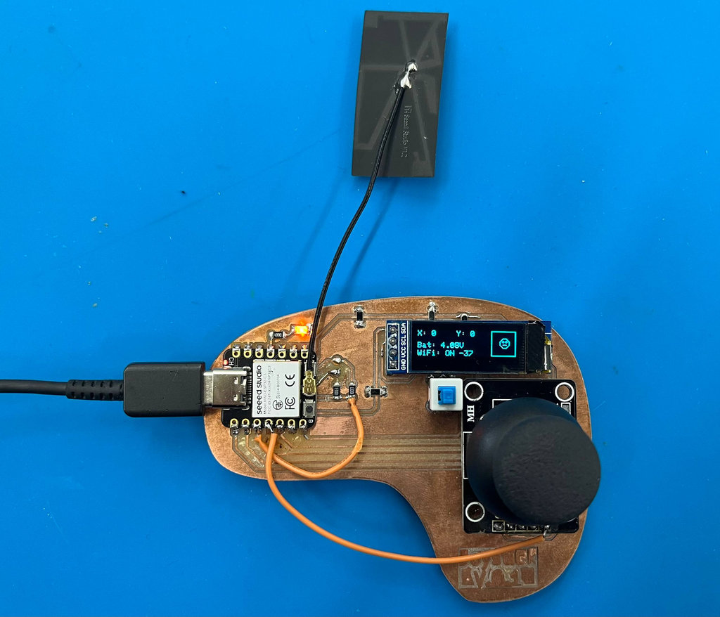
Since I am documenting this part after my final project is almost complete, don't be surprised that the 3D models of both the joystick and the car are already finished. 😄
To create the new joystick PCB, I only added protection resistors to the previous version and replaced the LCD. The new LCD still uses the same four pins, but their positions are different. You can see the previous version in Week 9.
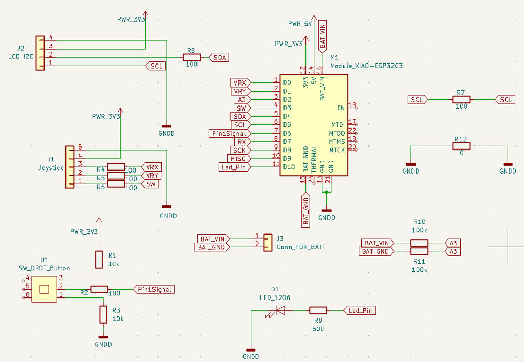
Here is the Schematic design.
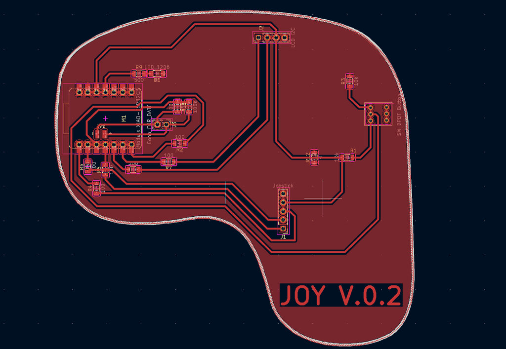
And here is the final PCB layout.
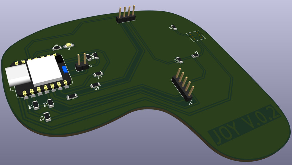
Here is the 3D view exported from KiCad.
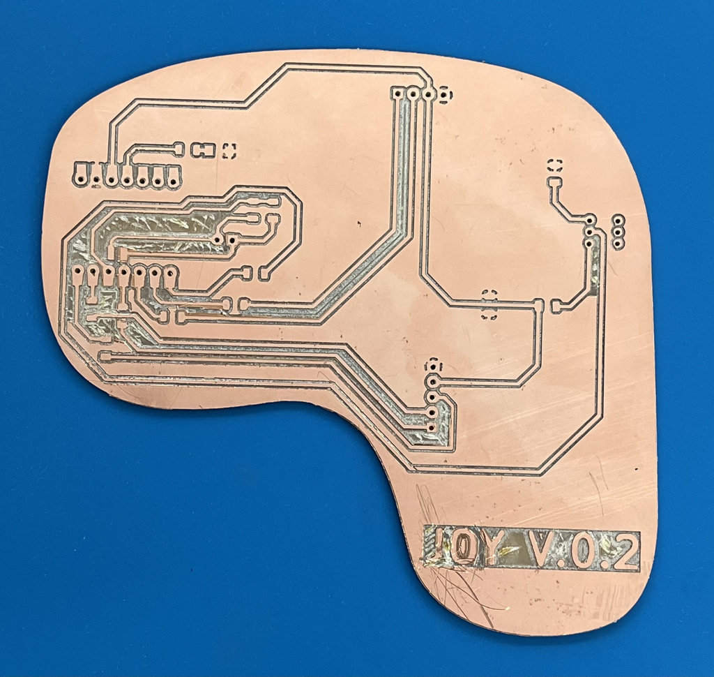
After milling the PCB, and since my PCB blank was copper-clad on both sides, I removed the copper around the pin areas on the back side to avoid unwanted conductivity.
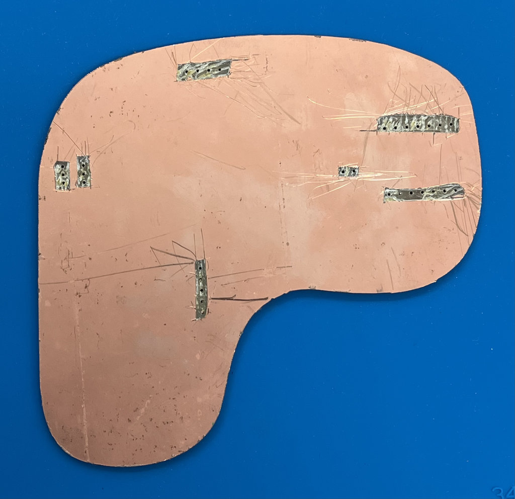
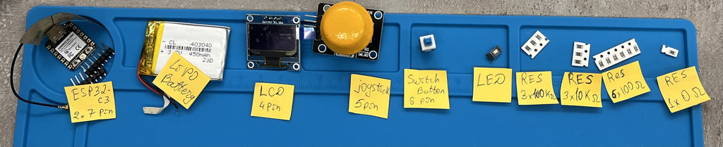
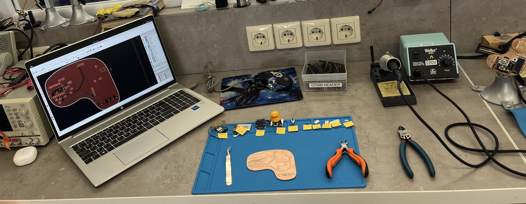
Here comes my favorite part—the PCB is assembled and ready for the soldering process.
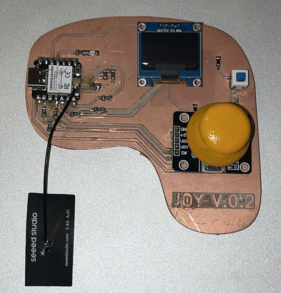
And here is the finished joystick PCB.
For this week, I actually used two different types of wireless connection, so before showing the code, here are quick sketches of how each one works.
WiFi/UDP is what I used first, to test that my joystick's data was actually readable on my PC. ESP-NOW is what I ended up using for the real thing — direct communication between the joystick and the car. Below, I explain where each one is used.
ESP-NOW diagram
And here is a sketch of how ESP-NOW works between my two boards.
Unlike WiFi, there is no router or network in the middle here — the joystick and the car talk to each other directly, like two walkie-talkies. The car already knows the joystick's MAC address, so it just listens for packets coming from that exact address and ignores everything else.
WiFi/UDP diagram
Here is a simple sketch of how the joystick talks to my PC over WiFi.
This one is different from ESP-NOW — here both my joystick and my PC connect to the same WiFi network (my phone's hotspot), and the router is the one passing messages between them. The Car doesn't "call" the PC directly, it just fires small UDP packets containing the X and Y values into the network, addressed to my PC's IP and port 4210, and my Python script sitting on the PC just listens on that port and prints whatever arrives.
With the help of my good friend Claude's programming knowledge 😄, I asked him to "Write two Arduino programs for two Seeed Studio XIAO ESP32-C3 boards communicating via ESP-NOW. One acts as a wireless joystick controller with an SSD1306 OLED, battery monitoring, push button, and joystick. The second controls a robot car with dual A4953 motor drivers, an RC522 NFC reader, and an I²C LCD. The robot collects NFC coins, tracks score and time, and sends game status back to the controller, which displays waiting, gameplay, game over, and victory screens.".
Here is the code he generated for the joystick. I modified several parameters and also corrected the pin assignments.
#include <esp_now.h>
#include <WiFi.h>
#include <Wire.h>
#include <Adafruit_SSD1306.h>

// ── Car fixed MAC ─────────────────────────────────────────────
uint8_t carMAC[] = {0x36, 0x33, 0x33, 0x33, 0x33, 0x33};

// ── Pin Definitions ───────────────────────────────────────────
#define PIN_VRX    2
#define PIN_VRY    3
#define PIN_BATT   4
#define PIN_SW     5
#define PIN_SDA    6
#define PIN_SCL    7
#define PIN_POWER  21
#define PIN_LED    10

// ── OLED ──────────────────────────────────────────────────────
#define SCREEN_W 128
#define SCREEN_H 64
Adafruit_SSD1306 display(SCREEN_W, SCREEN_H, &Wire, -1);

// ── Game config ───────────────────────────────────────────────
#define TOTAL_COINS 5

// ── Joystick Calibration Constants ────────────────────────────
#define JOY_CENTER 2048    // Center position of a 12-bit ADC
#define JOY_DEADZONE 500   // Increase this value to require MORE physical stick movement

// ── Payloads ──────────────────────────────────────────────────
typedef struct {
  int   vrx;
  int   vry;
  bool  sw;
  float battPct;
} JoyData;

typedef struct {
  int           coins;
  int           timeLeft;
  bool          coinJustCollected;
  bool          win;
  bool          gameover;
  bool          waiting;
  unsigned long winTimeMs;
} CarData;

JoyData  joyData;
CarData  carData;
volatile bool newCarData = false;

// ── ESP-NOW callbacks ─────────────────────────────────────────
void onSent(const wifi_tx_info_t *info, esp_now_send_status_t status) { }

void onReceive(const esp_now_recv_info_t *info,
               const uint8_t *data, int len) {
  if (len == sizeof(CarData)) {
    memcpy(&carData, data, sizeof(CarData));
    newCarData = true;
  }
}

// ── Battery percentage ────────────────────────────────────────
float readBattPct() {
  int raw = analogRead(PIN_BATT);
  float voltage = raw * (3.3f / 4095.0f) * 3.0f;
  float pct = (voltage - 6.0f) / (8.4f - 6.0f) * 100.0f;
  return constrain(pct, 0.0f, 100.0f);
}

// ── Draw faces ────────────────────────────────────────────────
void drawSadFace(int cx, int cy) {
  display.drawCircle(cx, cy, 14, SSD1306_WHITE);
  display.fillCircle(cx - 5, cy - 4, 2, SSD1306_WHITE);
  display.fillCircle(cx + 5, cy - 4, 2, SSD1306_WHITE);
  for (int x = -6; x <= 6; x++) {
    int y = cy + 6 + (x * x) / 8;
    display.drawPixel(cx + x, y, SSD1306_WHITE);
  }
}

void drawHappyFace(int cx, int cy) {
  display.drawCircle(cx, cy, 14, SSD1306_WHITE);
  display.fillCircle(cx - 5, cy - 4, 2, SSD1306_WHITE);
  display.fillCircle(cx + 5, cy - 4, 2, SSD1306_WHITE);
  for (int x = -6; x <= 6; x++) {
    int y = cy + 8 - (x * x) / 8;
    display.drawPixel(cx + x, y, SSD1306_WHITE);
  }
}

// ── OLED screens ──────────────────────────────────────────────
void showWaiting() {
  display.clearDisplay();
  display.setTextSize(1);
  display.setTextColor(SSD1306_WHITE);
  display.setCursor(20, 5);
  display.println("COIN COLLECTOR");

  display.setCursor(10, 17);
  display.setTextSize(2);
  display.println(" Press SW  to start");

  display.setTextColor(SSD1306_BLACK, SSD1306_WHITE);
  display.setTextSize(1);
  display.setCursor(30, 55);
  display.println("  Good luck!  ");
  display.display();
}

void showPlaying(int coins, int timeLeft, float batt) {
  display.clearDisplay();
  display.setTextColor(SSD1306_WHITE);

  // Timer countdown (big)
  display.setTextSize(2);
  display.setCursor(0, 0);
  int m = timeLeft / 60;
  int s = timeLeft % 60;
  display.printf("%02d:%02d", m, s);

  // Coins count
  display.setTextSize(1);
  display.setCursor(80, 4);
  display.printf("C:%d/%d", coins, TOTAL_COINS);

  // Battery
  display.setCursor(80, 16);
  display.printf("B:%.0f%%", batt);

  // Divider
  display.drawLine(0, 25, 128, 25, SSD1306_WHITE);

  // Coin icons
  display.setCursor(5, 30);
  display.setTextSize(1);
  display.print("Coins:");
  for (int i = 0; i < TOTAL_COINS; i++) {
    int x = 12 + i * 24;
    int y = 42;
    if (i < coins) {
      display.fillCircle(x, y+6, 9, SSD1306_WHITE);
      display.setTextColor(SSD1306_BLACK);
      display.setCursor(x - 3, y+3);
      display.print(i + 1);
      display.setTextColor(SSD1306_WHITE);
    } else {
      display.drawCircle(x, y+6, 9, SSD1306_WHITE);
      display.setCursor(x - 3, y+3);
      display.print(i + 1);
    }
  }

  display.display();
}

void showGameOver(int coins) {
  display.clearDisplay();
  display.setTextColor(SSD1306_WHITE);
  drawSadFace(108, 22);
  display.setTextSize(1);
  display.setCursor(0, 0);
  display.println("GAME OVER :(");
  display.drawLine(0, 12, 90, 12, SSD1306_WHITE);
  display.setCursor(0, 18);
  display.printf("Coins: %d/%d", coins, TOTAL_COINS);
  display.setCursor(0, 32);
  display.println("Better luck");
  display.println("next time!");
  display.setCursor(0, 52);
  display.println("SW = restart");
  display.display();
}

void showWin(unsigned long winMs, int coins) {
  display.clearDisplay();
  display.setTextColor(SSD1306_WHITE);
  drawHappyFace(108, 22);
  display.setTextSize(1);
  display.setCursor(0, 0);
  display.println("YOU WON! :)");
  display.drawLine(0, 12, 90, 12, SSD1306_WHITE);
  display.setCursor(0, 18);
  int m  = (winMs / 1000) / 60;
  int s  = (winMs / 1000) % 60;
  int ms = (winMs % 1000) / 10;
  display.printf("Time:%02d:%02d.%02d", m, s, ms);
  display.setCursor(0, 32);
  display.printf("All %d coins!", coins);
  display.setCursor(0, 46);
  display.println("Congratulations!");
  display.setCursor(0, 56);
  display.println("SW = play again");
  display.display();
}

void setup() {
  Serial.begin(115200);

  pinMode(PIN_BATT, INPUT);
  pinMode(PIN_SW,    INPUT_PULLUP);
  pinMode(PIN_POWER, INPUT_PULLUP);
  pinMode(PIN_LED,   OUTPUT);
  digitalWrite(PIN_LED, HIGH);

  Wire.begin(PIN_SDA, PIN_SCL);
  display.begin(SSD1306_SWITCHCAPVCC, 0x3C);
  display.setTextColor(SSD1306_WHITE);
  display.clearDisplay();
  display.setCursor(0, 0);
  display.setTextSize(1);
  display.println("Starting...");
  display.display();

  WiFi.mode(WIFI_STA);
  esp_now_init();
  esp_now_register_send_cb(onSent);
  esp_now_register_recv_cb(onReceive);

  esp_now_peer_info_t peer = {};
  memcpy(peer.peer_addr, carMAC, 6);
  peer.channel = 0;
  peer.encrypt = false;
  esp_now_add_peer(&peer);

  showWaiting();
}

void loop() {
  // ── Power switch ──────────────────────────────────────────
  if (digitalRead(PIN_POWER) == LOW) {
    display.clearDisplay();
    display.display();
    display.ssd1306_command(SSD1306_DISPLAYOFF);
    digitalWrite(PIN_LED, LOW);

    joyData.vrx = 2139; joyData.vry = 2248;
    joyData.sw  = false; joyData.battPct = 0;
    esp_now_send(carMAC, (uint8_t*)&joyData, sizeof(joyData));

    while (digitalRead(PIN_POWER) == LOW) { delay(100); }

    display.ssd1306_command(SSD1306_DISPLAYON);
    digitalWrite(PIN_LED, HIGH);
    showWaiting();
    delay(300);
  }

  // ── Read raw joystick values ──────────────────────────────
  int rawX = analogRead(PIN_VRX);
  int rawY = analogRead(PIN_VRY);

  // ── Apply Deadzone Filter ─────────────────────────────────
  // If the movement is small (inside the deadzone), force it to center
  if (abs(rawX - JOY_CENTER) < JOY_DEADZONE) {
    joyData.vrx = JOY_CENTER;
  } else {
    joyData.vrx = rawX;
  }

  if (abs(rawY - JOY_CENTER) < JOY_DEADZONE) {
    joyData.vry = JOY_CENTER;
  } else {
    joyData.vry = rawY;
  }

  joyData.sw      = (digitalRead(PIN_SW) == LOW);
  joyData.battPct = readBattPct();

  esp_now_send(carMAC, (uint8_t*)&joyData, sizeof(joyData));

  // ── Handle incoming car data ──────────────────────────────
  if (newCarData) {
    newCarData = false;

    if (carData.coinJustCollected) {
      for (int i = 0; i < 3; i++) {
        digitalWrite(PIN_LED, LOW);  delay(150);
        digitalWrite(PIN_LED, HIGH); delay(150);
      }
    }

    if (carData.waiting) {
      showWaiting();
    } else if (carData.win) {
      showWin(carData.winTimeMs, carData.coins);
    } else if (carData.gameover) {
      showGameOver(carData.coins);
    } else {
      showPlaying(carData.coins, carData.timeLeft, joyData.battPct);
    }
  }

  delay(50);
}
And this is the code for the robot car.
#include <esp_now.h>
#include <WiFi.h>
#include <SPI.h>
#include <MFRC522.h>
#include "esp_wifi.h"

// ── Fixed MAC ─────────────────────────────────────────────────
uint8_t fixedMAC[] = {0x36, 0x33, 0x33, 0x33, 0x33, 0x33};

// ── Motor Pins (A4953) ────────────────────────────────────────
#define MOTOR_A_IN1   2
#define MOTOR_A_IN2   3
#define MOTOR_B_IN1   5
#define MOTOR_B_IN2   6

// ── Other Pins ────────────────────────────────────────────────
#define PIN_LED      21

// ── NFC (RC522) ───────────────────────────────────────────────
#define NFC_MOSI     10
#define NFC_MISO      9
#define NFC_RST       8
#define NFC_SCK      20
#define NFC_SS        7

MFRC522 nfc(NFC_SS, NFC_RST);

// ── Joystick calibration ──────────────────────────────────────
#define JOY_CENTER_X  2139
#define JOY_CENTER_Y  2248
#define JOY_DEAD       300
#define JOY_MAX       2048

// ── PWM config ────────────────────────────────────────────────
#define PWM_FREQ      5000
#define PWM_RES          8

// ── Signal watchdog ───────────────────────────────────────────
#define SIGNAL_TIMEOUT_MS 500
unsigned long lastReceiveTime = 0;

// ── Game config ───────────────────────────────────────────────
#define TOTAL_COINS    5
#define GAME_TIME_SEC  180

// ── NFC tag UIDs (7 bytes each) ───────────────────────────────
uint8_t coinTags[TOTAL_COINS][7] = {
  {0x1D, 0x05, 0x99, 0xC5, 0x08, 0x10, 0x80},
  {0x1D, 0x02, 0x99, 0xC5, 0x08, 0x10, 0x80},
  {0x1D, 0x04, 0x99, 0xC5, 0x08, 0x10, 0x80},
  {0x1D, 0xF7, 0x98, 0xC5, 0x08, 0x10, 0x80},
  {0x1D, 0x03, 0x99, 0xC5, 0x08, 0x10, 0x80}
};
bool coinCollected[TOTAL_COINS] = {false};

// ── Game state ────────────────────────────────────────────────
enum GameState { WAITING, PLAYING, WIN, GAMEOVER };
GameState gameState = WAITING;
unsigned long gameStartTime = 0;
int coinsCollected = 0;
unsigned long winTime = 0;

// ── Payloads ──────────────────────────────────────────────────
typedef struct {
  int   vrx;
  int   vry;
  bool  sw;
  float battPct;
} JoyData;

typedef struct {
  int           coins;
  int           timeLeft;
  bool          coinJustCollected;
  bool          win;
  bool          gameover;
  bool          waiting;
  unsigned long winTimeMs;
} CarData;

JoyData rxData;
volatile bool newData = false;
uint8_t joystickMac[6];
bool joystickMacKnown = false;

// ── ESP-NOW receive callback ──────────────────────────────────
void onReceive(const esp_now_recv_info_t *info,
               const uint8_t *data, int len) {
  if (len == sizeof(JoyData)) {
    memcpy(&rxData, data, sizeof(JoyData));
    newData = true;
    lastReceiveTime = millis();

    if (!joystickMacKnown) {
      memcpy(joystickMac, info->src_addr, 6);
      esp_now_peer_info_t peer = {};
      memcpy(peer.peer_addr, joystickMac, 6);
      peer.channel = 0;
      peer.encrypt = false;
      esp_now_add_peer(&peer);
      joystickMacKnown = true;
    }
  }
}

// ── Send state to joystick ────────────────────────────────────
void sendCarData(bool coinJust) {
  if (!joystickMacKnown) return;
  CarData cd;
  int elapsed  = (millis() - gameStartTime) / 1000;
  cd.timeLeft          = max(0, GAME_TIME_SEC - elapsed);
  cd.coins             = coinsCollected;
  cd.coinJustCollected = coinJust;
  cd.win               = (gameState == WIN);
  cd.gameover          = (gameState == GAMEOVER);
  cd.waiting           = (gameState == WAITING);
  cd.winTimeMs         = winTime;
  esp_now_send(joystickMac, (uint8_t*)&cd, sizeof(cd));
}

// ── Motor control ─────────────────────────────────────────────
void setMotorA(int speed) {
  speed = constrain(speed, -255, 255);
  if (speed > 0)      { ledcWrite(MOTOR_A_IN1, speed); ledcWrite(MOTOR_A_IN2, 0);      }
  else if (speed < 0) { ledcWrite(MOTOR_A_IN1, 0);     ledcWrite(MOTOR_A_IN2, -speed); }
  else                { ledcWrite(MOTOR_A_IN1, 0);     ledcWrite(MOTOR_A_IN2, 0);      }
}
void setMotorB(int speed) {
  speed = constrain(speed, -255, 255);
  if (speed > 0)      { ledcWrite(MOTOR_B_IN1, speed); ledcWrite(MOTOR_B_IN2, 0);      }
  else if (speed < 0) { ledcWrite(MOTOR_B_IN1, 0);     ledcWrite(MOTOR_B_IN2, -speed); }
  else                { ledcWrite(MOTOR_B_IN1, 0);     ledcWrite(MOTOR_B_IN2, 0);      }
}
void stopAll() { setMotorA(0); setMotorB(0); }

// ── Tank drive ────────────────────────────────────────────────
void tankDrive(int vrx, int vry) {
  int y = vry - JOY_CENTER_Y;
  int x = vrx - JOY_CENTER_X;
  if (abs(y) < JOY_DEAD) y = 0;
  if (abs(x) < JOY_DEAD) x = 0;
  if (y == 0 && x == 0) { stopAll(); return; }
  int thrust = map(-y, -JOY_MAX, JOY_MAX, -255, 255);
  int turn   = map( x, -JOY_MAX, JOY_MAX, -255, 255);
  setMotorA(constrain(thrust + turn, -255, 255));
  setMotorB(constrain(thrust - turn, -255, 255));
}

// ── Match coin tag ────────────────────────────────────────────
int matchCoin(byte *uid, byte size) {
  if (size != 7) return -1;
  for (int i = 0; i < TOTAL_COINS; i++) {
    if (!coinCollected[i] &&
        memcmp(uid, coinTags[i], 7) == 0) {
      return i;
    }
  }
  return -1;
}

// ── Reset game ────────────────────────────────────────────────
void resetGame() {
  gameState      = PLAYING;
  coinsCollected = 0;
  winTime        = 0;
  gameStartTime  = millis();
  for (int i = 0; i < TOTAL_COINS; i++) coinCollected[i] = false;
  Serial.println("Game started!");
}

void setup() {
  Serial.begin(115200);

  ledcAttach(MOTOR_A_IN1, PWM_FREQ, PWM_RES);
  ledcAttach(MOTOR_A_IN2, PWM_FREQ, PWM_RES);
  ledcAttach(MOTOR_B_IN1, PWM_FREQ, PWM_RES);
  ledcAttach(MOTOR_B_IN2, PWM_FREQ, PWM_RES);
  stopAll();

  pinMode(PIN_LED, OUTPUT);
  digitalWrite(PIN_LED, LOW);

  SPI.begin(NFC_SCK, NFC_MISO, NFC_MOSI, NFC_SS);
  nfc.PCD_Init();

  WiFi.mode(WIFI_STA);
  esp_wifi_set_mac(WIFI_IF_STA, fixedMAC);
  if (esp_now_init() != ESP_OK) return;
  esp_now_register_recv_cb(onReceive);

  lastReceiveTime = millis();
  Serial.println("Car ready. Press SW on joystick to start.");
}

void loop() {
  int elapsed  = (millis() - gameStartTime) / 1000;
  int timeLeft = max(0, GAME_TIME_SEC - elapsed);

  // ── Timer expired ─────────────────────────────────────────
  if (gameState == PLAYING && timeLeft == 0) {
    gameState = GAMEOVER;
    stopAll();
    sendCarData(false);
    Serial.println("Game Over!");
  }

  // ── Signal timeout watchdog ───────────────────────────────
  if (millis() - lastReceiveTime > SIGNAL_TIMEOUT_MS) {
    stopAll();
  }

  // ── Joystick input ────────────────────────────────────────
  if (newData) {
    newData = false;

    // SW button pressed = start or restart game
    if (rxData.sw) {
      resetGame();
      sendCarData(false);
    } else {
      // Only drive during PLAYING state
      if (gameState == PLAYING) {
        tankDrive(rxData.vrx, rxData.vry);
      } else {
        stopAll();
      }
    }
  }

  // ── NFC scan (only while playing) ────────────────────────
  if (gameState == PLAYING &&
      nfc.PICC_IsNewCardPresent() && nfc.PICC_ReadCardSerial()) {

    // ── DELETE this block after testing ──────────────────
    Serial.print("TAG UID: ");
    for (byte i = 0; i < nfc.uid.size; i++) {
      Serial.printf("%02X ", nfc.uid.uidByte[i]);
    }
    Serial.println();
    // ── END delete block ──────────────────────────────────

    int idx = matchCoin(nfc.uid.uidByte, nfc.uid.size);
    if (idx >= 0) {
      coinCollected[idx] = true;
      coinsCollected++;
      Serial.printf("Coin %d collected! Total: %d/%d\n",
                    idx + 1, coinsCollected, TOTAL_COINS);

      // Flash car LED
      for (int i = 0; i < 3; i++) {
        digitalWrite(PIN_LED, HIGH); delay(150);
        digitalWrite(PIN_LED, LOW);  delay(150);
      }

      // Check win
      if (coinsCollected >= TOTAL_COINS) {
        gameState = WIN;
        winTime   = millis() - gameStartTime;
        stopAll();
        Serial.printf("YOU WIN! Time: %lums\n", winTime);
      }

      sendCarData(true);
    }

    nfc.PICC_HaltA();
    nfc.PCD_StopCrypto1();
  }

  // ── Periodic state update to joystick ────────────────────
  static unsigned long lastSend = 0;
  if (millis() - lastSend > 200) {
    lastSend = millis();
    sendCarData(false);
  }
}
Below is a short demonstration video showing the communication between the car and the joystick. The complete logic of the code and a detailed explanation will be presented in the final week of my documentation.
Code Explanation
ESP-NOW AddressingESP-NOW does not use IP addresses like WiFi communication. Instead, every ESP32 has a unique MAC address that identifies it on the wireless network.
In my project, the joystick already knows the car's MAC address:
uint8_t carMAC[] = {0x36, 0x33, 0x33, 0x33, 0x33, 0x33};During setup(), I register this board as an ESP-NOW peer:
esp_now_peer_info_t peer = {};
memcpy(peer.peer_addr, carMAC, 6);
esp_now_add_peer(&peer);
This tells the joystick exactly where to send every joystick packet.
On the robot car, I do not hardcode the joystick MAC address.
Instead, when the first packet arrives, the receive callback automatically stores the sender's MAC address:
memcpy(joystickMac, info->src_addr, 6);Then it registers the joystick as a peer:
esp_now_add_peer(&peer);After that, the car can send game information back to the joystick.
The joystick sends data using:
esp_now_send(carMAC,
(uint8_t*)&joyData,
sizeof(joyData));
This function packages the joystick structure and transmits it wirelessly to the ESP32 whose MAC address is stored in carMAC.
For the car:
esp_now_send(joystickMac,
(uint8_t*)&cd,
sizeof(cd));
This sends the updated game status back to the joystick.
Receiving Data
For joystick:
void onReceive(const esp_now_recv_info_t *info,
	const uint8_t *data, int len) {
  	if (len == sizeof(CarData)) {
    	memcpy(&carData, data, sizeof(CarData));
    	newCarData = true;
  	}
}
This callback automatically executes whenever the joystick receives a packet from the car. It copies the received bytes into the CarData structure and sets newCarData = true, allowing the main loop to safely update the display.
For the car:
void onReceive(const esp_now_recv_info_t *info,
	const uint8_t *data, int len) {
	if (len == sizeof(JoyData)) {
		memcpy(&rxData, data, sizeof(JoyData));
		newData = true;
		lastReceiveTime = millis();

		if (!joystickMacKnown) {
			memcpy(joystickMac, info->src_addr, 6);
			esp_now_peer_info_t peer = {};
			memcpy(peer.peer_addr, joystickMac, 6);
			peer.channel = 0;
			peer.encrypt = false;
			esp_now_add_peer(&peer);
			joystickMacKnown = true;
		}
	}
}
On the robot car, this callback receives joystick commands. Every incoming packet contains the joystick position, button state, and battery level.
Bidirectional ESP-NOW Communication
The previous sections explain how the joystick sends commands to the robot car and how each board becomes addressable through its unique MAC address. However, my final project uses bidirectional ESP-NOW communication.
The joystick continuously sends the joystick position, button state, and battery level to the robot car. At the same time, the robot car sends the updated game information back to the joystick, including the number of collected NFC coins, the remaining game time, and the current game state (Waiting, Playing, Game Over, or Win).
This means that both ESP32-C3 boards can transmit and receive data, making each board independently addressable through its MAC address.
Bidirectional Communication Demonstration
The following video demonstrates the complete ESP-NOW communication between both boards.
When the robot car detects an NFC tag, it immediately sends the updated score and game status back to the joystick. The joystick receives this packet and updates the OLED display in real time, proving that communication happens in both directions.
Communication Flow
The complete communication sequence is shown below:
- The joystick sends its X/Y position, button state, and battery level to the robot car.
- The robot car receives the packet and controls both DC motors.
- When an NFC tag is detected, the robot updates the collected coin count.
- The robot immediately sends the updated game information back to the joystick using
esp_now_send(). - The joystick receives the packet through its
onReceive()callback and refreshes the OLED display with the new score and remaining game time.
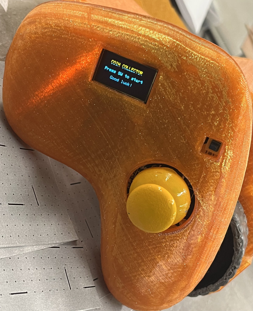
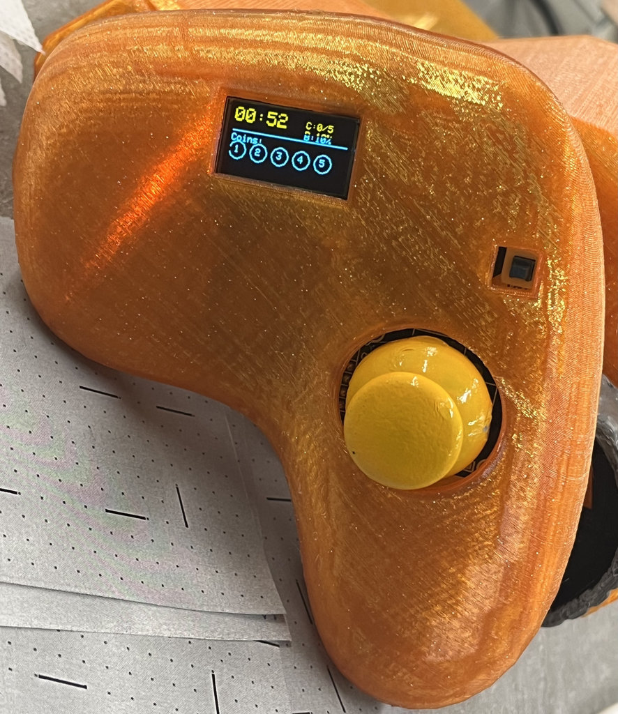
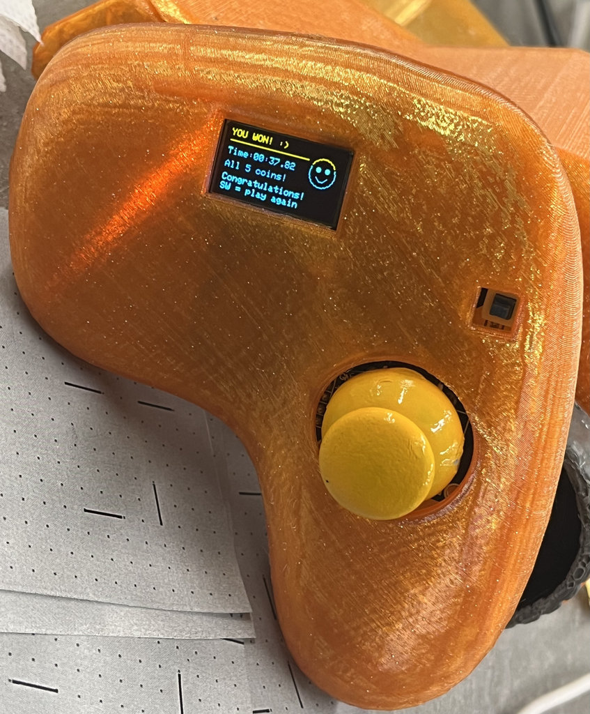
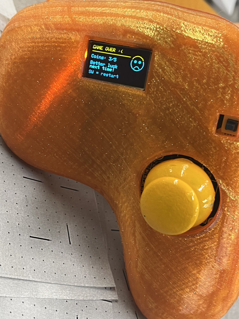
Joystick OLED User Interface
During the game, the joystick OLED guides the player through different stages. The display changes automatically according to the game state received from the robot car via ESP-NOW. The following images show each stage of the gameplay.
1. Press the joystick button to start the game.
2. Drive the robot and collect all 5 NFC coins. The OLED continuously displays the current score and remaining time.
3. After collecting all five coins, the robot sends the updated game status to the joystick, which displays the YOU WIN! screen.
4. If the timer expires before collecting all the coins, the robot sends a GAME OVER message, and the joystick updates the OLED accordingly.
Additional Experiment – WiFi Web Server Motor Control
Although this experiment is outside the required assignment criteria, I documented it because it helped me better understand WiFi networking before implementing ESP-NOW.
Now I am connecting the RC to WiFi as well.
- Libraries and Pin Setup
- Making the Web Page
- Getting the Speed Value
- Initialization (Setup)
- Driving the Motors (Loop)
- Showing the IP Address
First, I include the libraries for Wi-Fi and the Web Server. I define my motor pins exactly how they are connected to my RC PCB.
#include <WiFi.h>
#include <WebServer.h>
I created a function called handleRoot. This builds a simple website with a slider. When I move the slider on my PC, it sends the new speed value to the ESP32. I used a little bit of JavaScript so the page doesn't have to refresh every time I change the speed.
void handleRoot() {
  String html = "<html><body><h1>Motor Speed Control</h1>";
  html += "<input type='range' min='0' max='255' onchange='updateSpeed(this.value)'>";
  // JavaScript to send speed to ESP32
  html += "<script>function updateSpeed(val) { fetch('/setSpeed?val=' + val); }</script>";
  server.send(200, "text/html", html);
}This block handles the data coming from the PC. It looks for the "val" number from the slider and saves it into the currentSpeed variable so the motors can use it.
void handleSetSpeed() {
  if (server.hasArg("val")) {
    currentSpeed = server.arg("val").toInt();
  }
  server.send(200, "text/plain", "OK");
}In the setup, I configure my motor pins as outputs. I connect to my home Wi-Fi and tell the server which functions to run when I visit the IP address in my browser.
void setup() {
  pinMode(MOTOR_A_IN1, OUTPUT);
  pinMode(MOTOR_A_IN2, OUTPUT);
  // Connect WiFi
  WiFi.begin(ssid, password);
  // Routes for the web server
  server.on("/", handleRoot);
  server.on("/setSpeed", handleSetSpeed);
  server.begin();
}
In the loop, server.handleClient() stays listening for my PC. I use analogWrite instead of digitalWrite. This uses PWM to change the speed of the motors based on the currentSpeed variable (0 to 255).
void loop() {
  server.handleClient();
  // Send PWM signal to motors
  analogWrite(MOTOR_A_IN1, currentSpeed);
  digitalWrite(MOTOR_A_IN2, LOW);
  analogWrite(MOTOR_B_IN1, currentSpeed);
  digitalWrite(MOTOR_B_IN2, LOW);
}After the ESP32 connects to the Wi-Fi, I need to know which address to type into my browser. I added this part in the setup() to print the Local IP to the Serial Monitor. This way, I can see exactly where to visit to control my motors.
  // Check if WiFi is connected
  while (WiFi.status() != WL_CONNECTED) {
    delay(500);
    Serial.print(".");
  }

  // Print the IP address to the Serial Monitor
  Serial.println("");
  Serial.println("WiFi connected!");
  Serial.print("Visit this link to control speed: http://");
  Serial.println(WiFi.localIP());
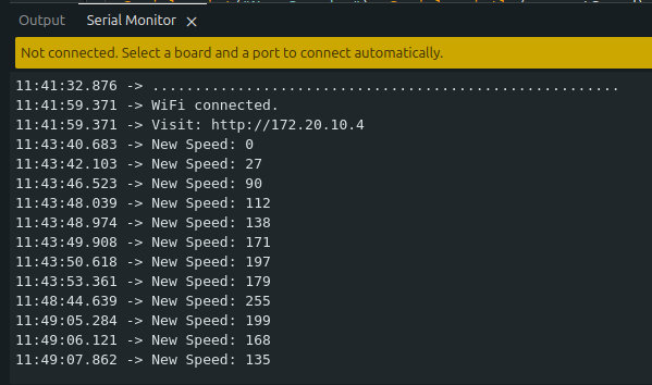
Here is the whole process shown in video format.
And here is the full code.
#include <WiFi.h>
#include <WebServer.h>

// --- MOTOR PINS ---
#define MOTOR_A_IN1 2
#define MOTOR_A_IN2 3
#define MOTOR_B_IN1 5
#define MOTOR_B_IN2 6

// --- WIFI CREDENTIALS ---
const char* ssid = "iPhone";
const char* password = "Manuela20";

WebServer server(80);
int currentSpeed = 255; // 0 to 255

void handleRoot() {
String html = "<html><body><h1>Motor Speed Control</h1>";
html += "<input type='range' min='0' max='255' onchange='updateSpeed(this.value)'>";
// JavaScript to send speed to ESP32
html += "<script>function updateSpeed(val) { fetch('/setSpeed?val=' + val); }</script>";
server.send(200, "text/html", html);
}
void handleSetSpeed() {
  if (server.hasArg("val")) {
    currentSpeed = server.arg("val").toInt();
    Serial.print("New Speed: "); Serial.println(currentSpeed);
  }
  server.send(200, "text/plain", "OK");
}

void setup() {
  Serial.begin(115200);

  pinMode(MOTOR_A_IN1, OUTPUT);
  pinMode(MOTOR_A_IN2, OUTPUT);
  pinMode(MOTOR_B_IN1, OUTPUT);
  pinMode(MOTOR_B_IN2, OUTPUT);

  WiFi.begin(ssid, password);
  while (WiFi.status() != WL_CONNECTED) { delay(500); Serial.print("."); }

  Serial.println("\nWiFi connected.");
  Serial.print("Visit: http://"); Serial.println(WiFi.localIP());

  server.on("/", handleRoot);
  server.on("/setSpeed", handleSetSpeed);
  server.begin();
}

void loop() {
  server.handleClient(); // Handle incoming web requests

  // Move Forward using the variable speed from the slider
  // On ESP32-C3, analogWrite sets the PWM duty cycle (0-255)
  analogWrite(MOTOR_A_IN1, currentSpeed);
  digitalWrite(MOTOR_A_IN2, LOW);
  analogWrite(MOTOR_B_IN1, currentSpeed);
  digitalWrite(MOTOR_B_IN2, LOW);
}
This week was both challenging and rewarding. I started by experimenting with WiFi/UDP communication to understand how my joystick could transmit data over a wireless network and verify the joystick values on my computer. This helped me better understand IP-based communication before moving to my final solution.
Afterwards, I implemented ESP-NOW communication between my joystick and robot car. Unlike WiFi, ESP-NOW uses the unique MAC address of each ESP32-C3 board, allowing them to communicate directly without a router. My final implementation supports bidirectional communication: the joystick sends movement commands, button states, and battery information to the robot car, while the robot sends the collected NFC coin count, remaining game time, and game status back to the joystick, where the OLED display updates in real time.
I also learned how callback functions make asynchronous communication possible, how both boards become individually addressable through their MAC addresses, and how different networking protocols can be selected depending on the application requirements.
Of course, not everything went smoothly. I accidentally uploaded the wrong firmware and managed to burn another ESP32-C3, which was frustrating. However, that experience also reminded me how important hardware protection and careful testing are during embedded development.
Although this week had its share of unexpected problems, it became one of the most valuable parts of my final project. It brought together networking, embedded programming, wireless communication, and hardware integration into a complete working system, and I learned a great deal from both the successful experiments and the mistakes along the way. 😄
Individual assignment
AI prompt:
“And Generate image when she fineshed Week 11”