Week 12/13
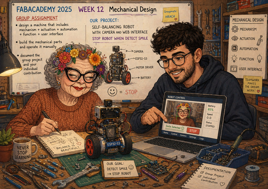
AI prompt:
“Please generate an image when she started week 12 "Mechanical Design" this week have only a group assignment part, and she works with her groupmate Hrach. We decided to create a self-balancing robot withh a camera and a web interface and need to when detect smile nned to stop Robot. group assignment: • design a machine that includes mechanism+actuation+automation+function+user interface • build the mechanical parts and operate it manually • document the group project and your individual contribution”
mechanical design, machine design
This week we had to create a machine that includes these points:
- design a machine that includes mechanism + actuation + automation + function + user interface
- build the mechanical parts and operate it manually
- document the group project and your individual contribution
There were many ideas, but in the end we decided to create a self-balancing robot. I also added the idea that our robot should have a camera that detects a smile, and when it detects it, it should lose balance 😄
It sounds like a fun idea, but to make it work requires serious and long-term effort. So after suggesting it, it also needed to be implemented. Of course, this made my main task more complicated, but I should have thought about it earlier 😄😄
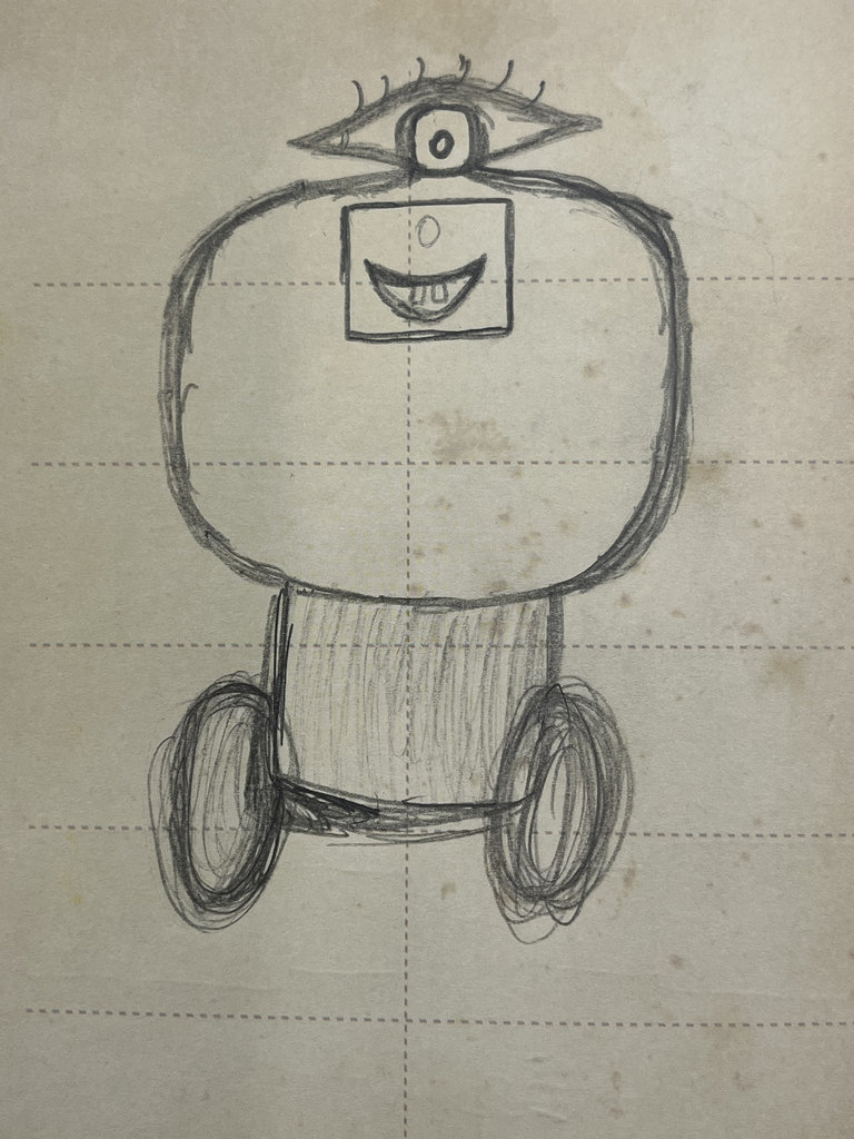
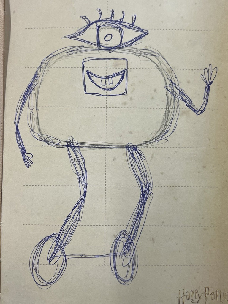
Here are some example sketches I created during my research.
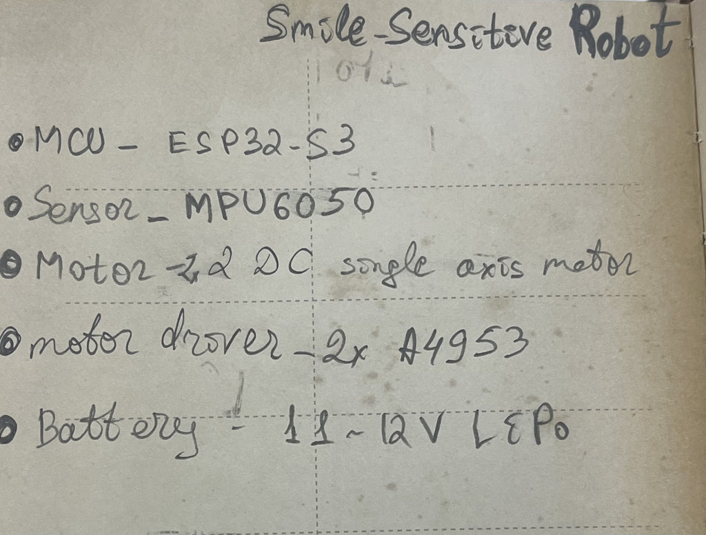
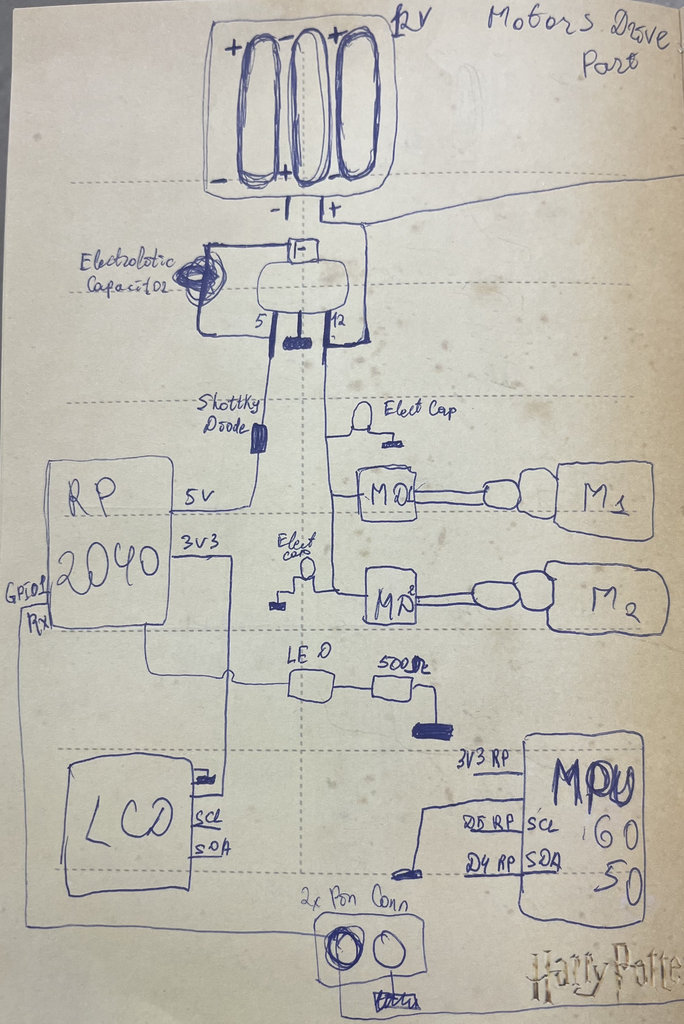
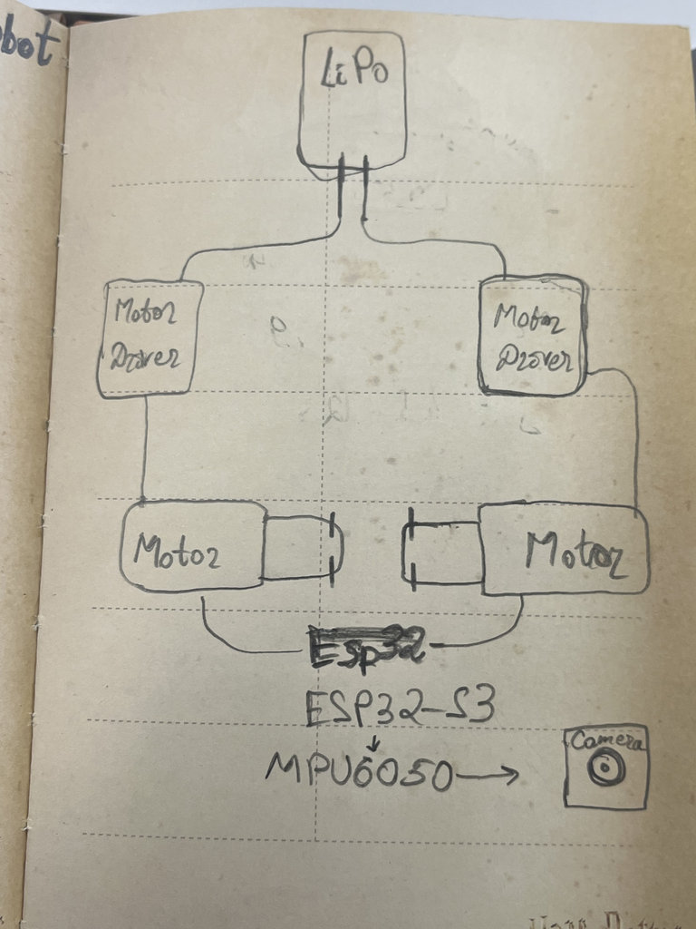
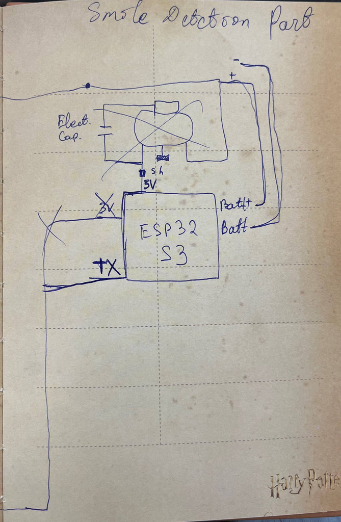
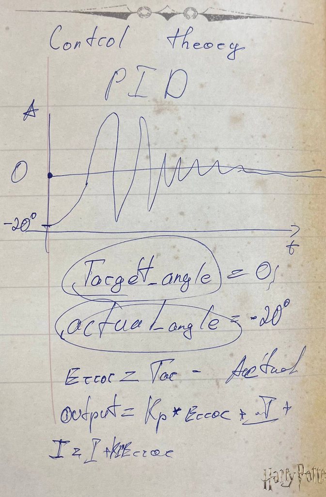
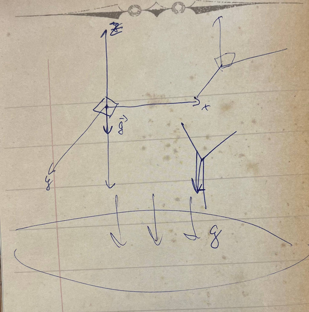
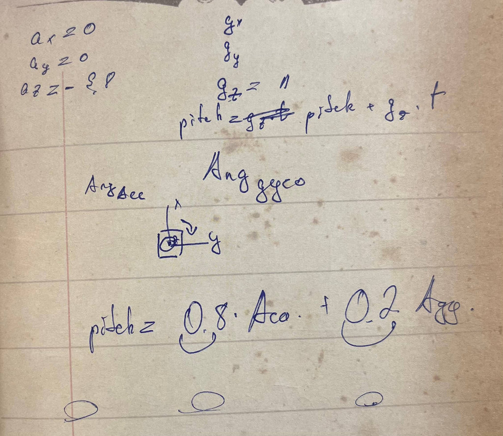
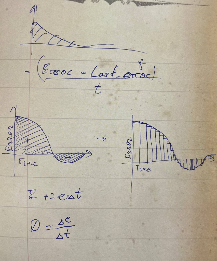
I can say that doing research this way helps me build stronger understanding. It becomes like a database for me — what I imagine at the beginning and what I get at the end.
After finishing the research, I started building the part of the robot responsible for maintaining balance. Since the robot will stand on two wheels, these are the components needed for the main functionality:
- MCU -
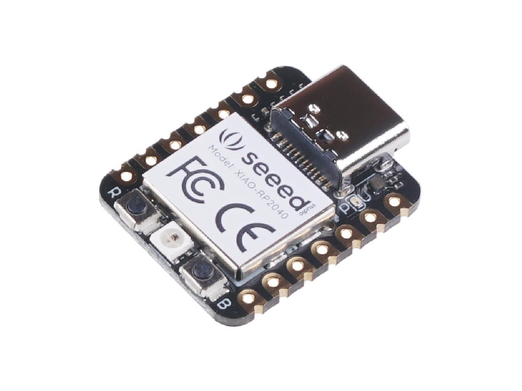
Seeed Studio XIAO RP2040 D0,D1– for motor driver IN1 and IN2 of the first motorD2,D3– for motor driver IN1 and IN2 of the second motorD4,D5– for SDA and SCL connections of LCD and MPU6050D6– used for LEDD7– this pin is very important, it is RX and will receive data from the face detection PCB- Sensor -
MPU6050 - 3-Axis Accelerometer – tells the robot which way is down
- 3-Axis Gyroscope – tells how fast it is falling
- 16-bit ADC – allows detecting very small movements
- Low cost – good for students and hobbyists
- Motor –
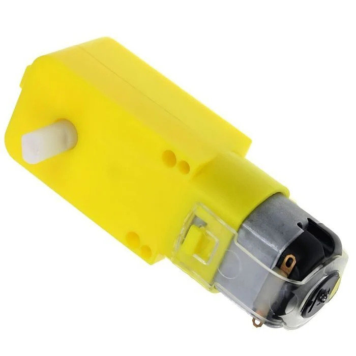
2x Single Axis TT DC Gear Motor (3–6V) - 2× Motor Drivers -
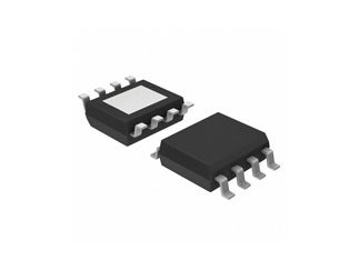
A4953 - Battery -
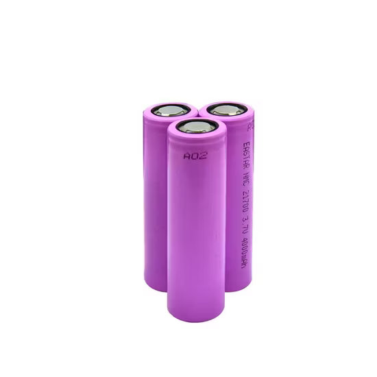
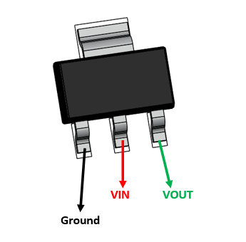
3x A 1200mAh 4.2V Lithium-Ion (or Li-Po) Battery - Voltage Regulator -
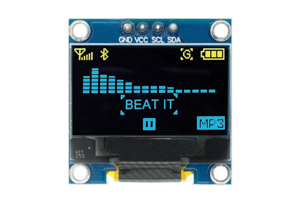
LM2940 - Display -
OLED LCD - Diode –
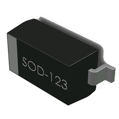
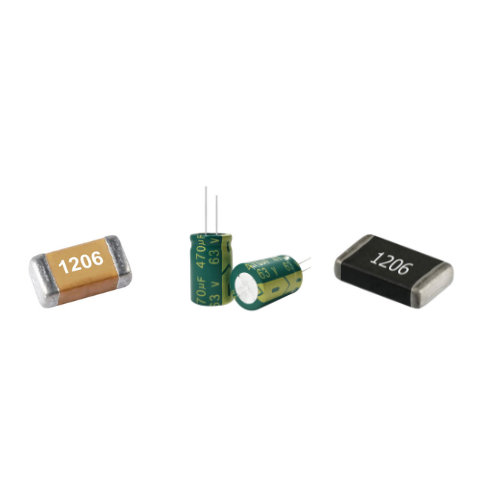
Schottky Diode SOD123 - Some resistors and capacitors
I will use pins D0 to D7 as follows:
The MPU6050 is the “gold standard” for balancing projects like self-balancing robots or drones.
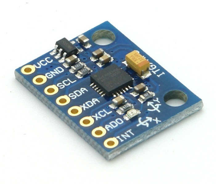
This is a compact and convenient option
This is the only motor driver available in our lab, but its minimum voltage is 8V, which is not ideal for lower voltages
I chose this battery because it is compact and easy to use.
Enough to power both motors and the MCU for the camera
The LM2940 is sensitive to noise, so I must use a good quality capacitor (at least 22µF) to keep the 5V stable
Compact size and there colors allows nice animations
I placed this near the 5V line so that when powering from battery, current from USB won’t damage the MCU.
For proper configuration and to avoid short circuits.
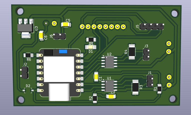
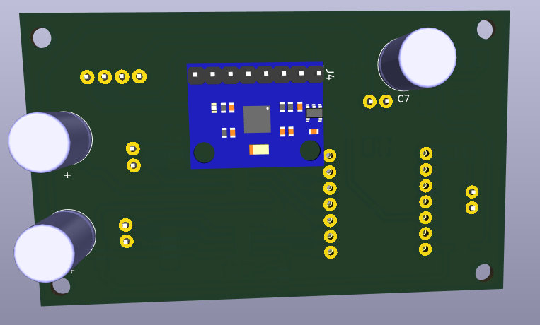
Now that I already know the required components and their purposes, I moved on to assembling the KiCad schematic and PCB designs.
Here is their final look.
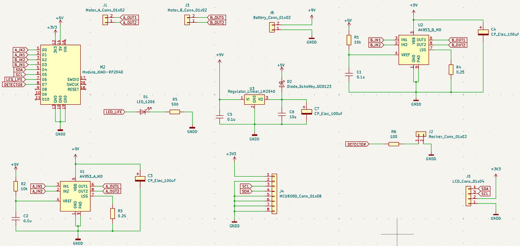
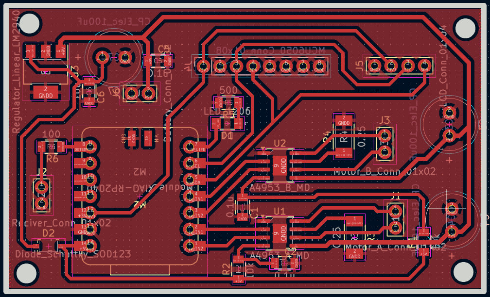
Also, the 3D designs.
Once the files were ready, it was time to generate the .nc files on modsproject.org for F.Cu and Edge.Cuts.
I’ve already milled so many PCBs that I switch really fast — first I change the bit to 1/64 to trace F.Cu, then switch again to 1/32 to cut Edge.Cuts and make the holes.
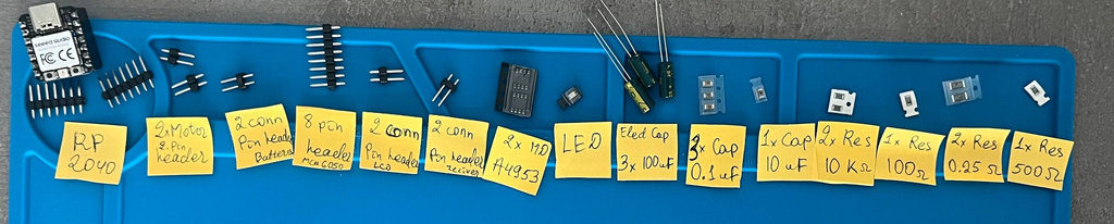
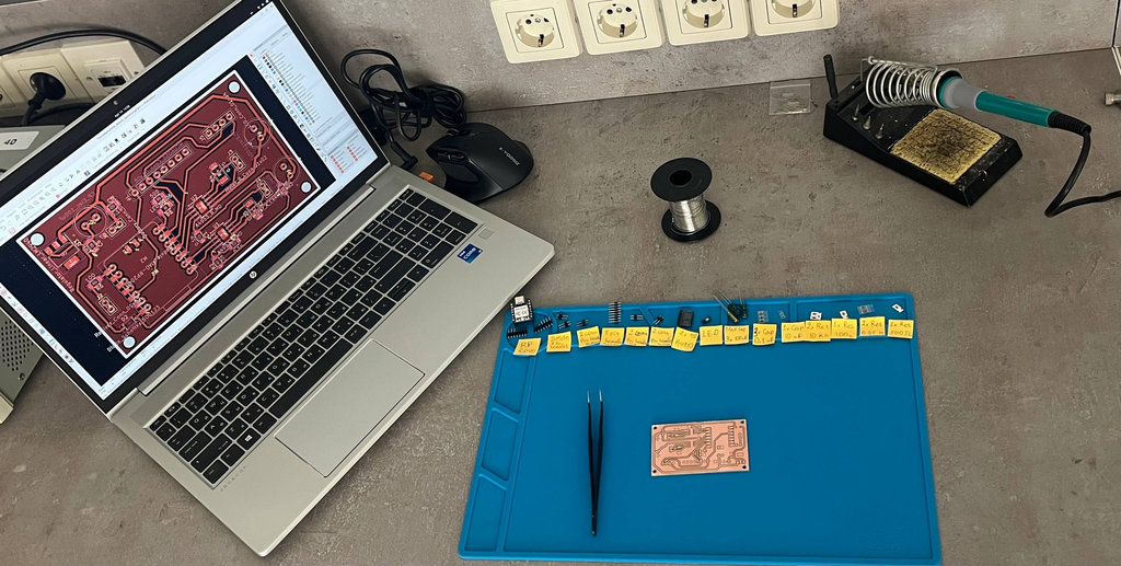
After finishing that, I prepare the workspace and start the soldering process.
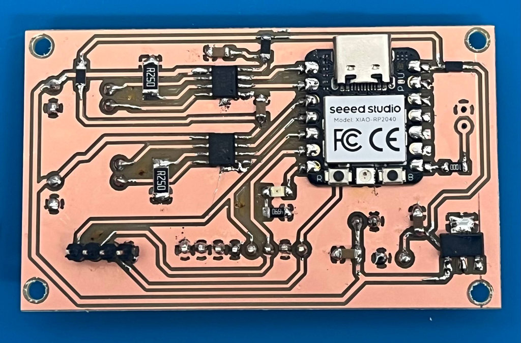
Here is the final result.
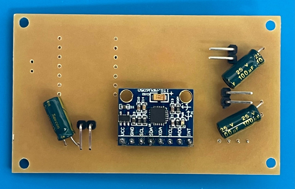
Now that the robot’s brain is complete, we can program it however we want. In this case, we need it to drive the motors and display the current angle data on the LCD.
I again asked my friend AI ヅ to "write code that initializes the MPU6050 accelerometer/gyroscope and the SSD1306 OLED display over the I²C interface. The code continuously reads the X, Y, and Z acceleration values, prints them to the Serial Monitor, displays them on the OLED screen, and drives two DC motors forward while indicating the system status using an LED".
Here is the complete code:
#include <Wire.h>
#include <Adafruit_MPU6050.h>
#include <Adafruit_Sensor.h>
#include <SPI.h>
#include <Adafruit_GFX.h>
#include <Adafruit_SSD1306.h>
#define SCREEN_WIDTH 128 // OLED display width, in pixels
#define SCREEN_HEIGHT 64 // OLED display height, in pixels
// Declaration for an SSD1306 display connected to I2C (SDA, SCL pins)
#define OLED_RESET -1 // Reset pin # (or -1 if sharing Arduino reset pin)
#define SCREEN_ADDRESS 0x3D
Adafruit_SSD1306 display(SCREEN_WIDTH, SCREEN_HEIGHT, &Wire, OLED_RESET);
// specific pins
const int sdaPin = 6;
const int sclPin = 7;
const int ledPin = 0;
const int motorAIN2 = 26;
const int motorAIN1 = 27;
const int motorBIN2 = 28;
const int motorBIN1 = 29;
Adafruit_MPU6050 mpu; void setup()
{
	Serial.begin(9600);
	while (!Serial); // Wait for Serial Monitor
	pinMode(motorAIN1, OUTPUT);
	pinMode(motorAIN2, OUTPUT);
	pinMode(motorBIN1, OUTPUT);
	pinMode(motorBIN2, OUTPUT);
	pinMode(ledPin, OUTPUT);
	digitalWrite(ledPin, HIGH);
	Serial.println("--- MPU6050 Hardware Check ---");
	// 1. Initialize I2C
	Wire.setSDA(sdaPin);
	Wire.setSCL(sclPin);
	Wire.begin();
	display.begin(SSD1306_SWITCHCAPVCC, 0x3C);
	display.clearDisplay(); display.display();
	// 2. Run a Quick Scan to see if the chip is even on the bus
	Serial.println("Scanning I2C bus...");
	byte count = 0;
	for (byte i = 1; i < 127; i++) {
		Wire.beginTransmission(i);
		if (Wire.endTransmission() == 0) {
			Serial.print("Found device at 0x");
			Serial.println(i, HEX); count++;
		}
	}
	if (count == 0) {
		Serial.println("ERROR: No I2C devices found at all. Check wiring/power.");
	}
	// 3. Try to start the MPU6050 (checking both common addresses)
	Serial.println("Attempting to connect to MPU6050...");
	if (!mpu.begin(0x68)) {
		// Default address
		if (!mpu.begin(0x69)) {
			// Alternate address
			Serial.println("FAILED: MPU6050 not responding at 0x68 or 0x69.");
			Serial.println("Double check: 3V3, GND, SDA(GPIO6), SCL(GPIO7)");
			return;
		}
	}
	Serial.println("SUCCESS: MPU6050 Connected!");
	// Configure sensor settings
	mpu.setAccelerometerRange(MPU6050_RANGE_8_G);
	mpu.setGyroRange(MPU6050_RANGE_500_DEG);
	mpu.setFilterBandwidth(MPU6050_BAND_21_HZ);
}
void loop() {
	sensors_event_t a, g, temp;
	mpu.getEvent(&a, &g, &temp);
	// --- Serial Output ---
	Serial.print("Accel X: ");
	Serial.print(a.acceleration.x);
	Serial.print(", Y: ");
	Serial.print(a.acceleration.y);
	Serial.print(", Z: ");
	Serial.print(a.acceleration.z);
	Serial.println(" m/s^2");
	// --- OLED Display Output ---
	display.clearDisplay();
	// Header Style
	display.setTextSize(1);
	display.setTextColor(SSD1306_WHITE);
	display.setCursor(0, 0);
	display.println("MPU6050 ACCEL (m/s2)");
	display.drawFastHLine(0, 10, 128, SSD1306_WHITE);
	// Decorative line // Data Style
	display.setTextSize(2);
	display.setCursor(0, 18);
	display.print("X: ");
	display.println(a.acceleration.x, 3);
	// 1 decimal place
	display.setCursor(0, 34);
	display.print("Y: ");
	display.println(a.acceleration.y, 3);
	display.setCursor(0, 50);
	display.print("Z: ");
	display.println(a.acceleration.z, 3);
	display.display();
	// Run Motors digitalWrite(motorAIN1, HIGH);
	digitalWrite(motorAIN2, LOW);
	digitalWrite(motorBIN1, HIGH);
	digitalWrite(motorBIN2, LOW);
	delay(200);
	// Slightly faster refresh for smoother reading
	Serial.println("Reading MPU6050...");
	mpu.getEvent(&a, &g, &temp);
	Serial.println("Driving Motors..."); // If you don't see this, the code is stuck above
}
And here is the video showing the result.
This code is not self-balancing because it lacks a closed-loop control system.
Why can’t an open loop balance (physical reason)? A balancing robot is like trying to keep a stick on your finger. If you randomly move your hand, it falls. If you don’t react to the tilt, it falls. We need to: detect the tilt, react immediately, continuously adjust movement. That’s why we need to add the following:
- State estimation (knowing tilt) — so the robot knows whether it’s tilting forward or backward, i.e. angle estimation (from accelerometer + gyro)
- Fixing the initial position — the robot must know the target balance angle and always aim for 0° (vertical)
- Error calculation — main equation: error = target − current. Without error, the system doesn’t know what to correct
- Control law (brain) — this is the key part for balancing and how the robot reacts to the error
Why simple control is not enough? It would be like: if 'fall forward' go forward, if 'fall backward' go backward. The problem is that this is too aggressive, causes sharp oscillations, and increases the risk of falling.
That’s why we need to study PID, which is basically a smarter brain.
We can break PID down like this:
- 🟢 P — Proportional (react to tilt)
- small tilt → small correction
- big tilt → strong correction
- 🟡 I — Integral (fix long-term drift)
- 🔵 D — Derivative (react to speed)
- slowly tilting → small correction
- falling fast → strong brake
P = Kp × error
Using only the proportional term means the correction is based only on the current tilt angle. The robot still balances by moving forward and backward, but without the Integral and Derivative terms the movement can be unstable and may cause oscillations around the upright position.
I = Ki × accumulated error
This fixes small constant tilt. For example, if the robot is always slightly tilted, it corrects that.
D = Kd × rate of change of error
This helps detect how fast the robot is falling.
So PID controls our motors.
motor speed = P + D (+ I)
🔁 Real-time loop (important): every few milliseconds
- Read angle
- Compute error
- Compute PID output
- Set motor speed/direction
After understanding all this, before having the final robot body, I needed to create a temporary body for testing.
With Hrach’s help, we made a simple body for our robot, and I was ready to start programming and testing.
Here are the first videos of the robot falling 🤪
And here is the code.
#include <Wire.h>
#include <Adafruit_GFX.h>
#include <Adafruit_SSD1306.h>

#define SCREEN_WIDTH 128
#define SCREEN_HEIGHT 64
Adafruit_SSD1306 display(SCREEN_WIDTH, SCREEN_HEIGHT, &Wire, -1);

// --- Motor Pins (L298N) ---
const int motorAIN1 = 27; const int motorAIN2 = 26; // Left Motor Dir
const int motorBIN1 = 29; const int motorBIN2 = 28; // Right Motor Dir

// --- MPU6050 ---
const int MPU_ADDR = 0x69;
int16_t AcX, AcZ, GyY;

// --- Sensor Fusion ---
float pitch = 0;       // Complementary filter output
float gyroAngle = 0;   // Gyroscope integrated angle

// --- PID Constants ---
float Kp = -30.0;
float Ki = 0.0;
float Kd = -1.0;
float targetAngle = 0.0;

// --- PID Variables ---
float error, lastError, cumError, rateError;
unsigned long lastTime;

// ─────────────────────────────────────────
void setup() {
  Serial.begin(115200);
  delay(2000);

  // --- Motor Pin Setup ---
  pinMode(motorAIN1, OUTPUT); pinMode(motorAIN2, OUTPUT);
  pinMode(motorBIN1, OUTPUT); pinMode(motorBIN2, OUTPUT);

  // --- Init OLED first (so we can show errors) ---
  Wire.setSDA(6); Wire.setSCL(7);
  Wire.begin();
  if (!display.begin(SSD1306_SWITCHCAPVCC, 0x3C)) for (;;);
  display.clearDisplay();
  display.setTextColor(SSD1306_WHITE);
  display.display();

  // --- I2C Bus Recovery ---
  // Release I2C pins back to GPIO to manually recover the bus
  Wire.end();
  pinMode(6, OUTPUT); pinMode(7, OUTPUT);
  digitalWrite(6, HIGH); digitalWrite(7, HIGH);
  delay(10);

  // Clock out any stuck slave (up to 9 pulses until SDA goes HIGH)
  pinMode(7, OUTPUT);
  for (int i = 0; i < 9; i++) {
    if (digitalRead(6) == HIGH) break;
    digitalWrite(7, LOW);  delayMicroseconds(5);
    digitalWrite(7, HIGH); delayMicroseconds(5);
  }

  // Send a manual STOP condition
  pinMode(6, OUTPUT);
  digitalWrite(7, LOW); delayMicroseconds(5);
  digitalWrite(6, LOW); delayMicroseconds(5);
  digitalWrite(7, HIGH); delayMicroseconds(5);
  digitalWrite(6, HIGH); delayMicroseconds(5);
  delay(10);

  // Re-init I2C properly
  Wire.setSDA(6); Wire.setSCL(7);
  Wire.begin();
  delay(100); // Give MPU6050 time to stabilize

  // --- Wake MPU6050 with retry ---
  bool mpuOK = false;
  for (int attempt = 0; attempt < 5; attempt++) {
    Wire.beginTransmission(MPU_ADDR);
    Wire.write(0x6B);
    Wire.write(0x00); // Clear sleep bit
    if (Wire.endTransmission(true) == 0) {
      mpuOK = true;
      break;
    }
    delay(50);
  }

  if (!mpuOK) {
    display.clearDisplay();
    display.setTextSize(1);
    display.setCursor(0, 0);
    display.print("MPU6050 FAIL!");
    display.setCursor(0, 12);
    display.print("Check wiring");
    display.setCursor(0, 24);
    display.print("or reset again");
    display.display();
    while (true); // Halt
  }

  // Show ready message
  display.clearDisplay();
  display.setTextSize(1);
  display.setCursor(20, 25);
  display.print("MPU6050 Ready!");
  display.display();
  delay(1000);

  lastTime = millis();
}

// ─────────────────────────────────────────
void loop() {
  // 1. Read MPU6050 Data
  Wire.beginTransmission(MPU_ADDR);
  Wire.write(0x3B);
  Wire.endTransmission(false);
  Wire.requestFrom(MPU_ADDR, 14, true);

  AcX = Wire.read() << 8 | Wire.read();
  Wire.read(); Wire.read();               // Skip AcY
  AcZ = Wire.read() << 8 | Wire.read();
  Wire.read(); Wire.read();               // Skip Temp
  Wire.read(); Wire.read();               // Skip GyX
  GyY = Wire.read() << 8 | Wire.read();  // Gyro Y (pitch rate)
  Wire.read(); Wire.read();               // Skip GyZ

  // 2. Complementary Filter for Pitch
  unsigned long currentTime = millis();
  float dt = (currentTime - lastTime) / 1000.0;
  lastTime = currentTime;

  // Accelerometer angle
  float accelAngle = atan2(AcX, AcZ) * 180.0 / M_PI;
  if (accelAngle < 180 && accelAngle > 0) accelAngle = 180 - accelAngle;
  else accelAngle = -1 * accelAngle - 180;

  // Gyroscope rate -> integrate into angle
  float gyroRate = GyY / 131.0; // 131 LSB per °/s at ±250°/s default
  gyroAngle = pitch + gyroRate * dt;

  // Complementary filter: gyro short-term + accel long-term drift correction
  pitch = 0.98 * gyroAngle + 0.02 * accelAngle;

  // 3. PID Calculation
  error = targetAngle - pitch;
  cumError += error * dt;
  rateError = (error - lastError) / dt;

  float motorPower = (Kp * error) + (Ki * cumError) + (Kd * rateError);

  lastError = error;

  // 4. Motor Execution & Safety
  if (abs(pitch) > 40) {  // Robot fell over — stop motors
    controlMotors(0);
    cumError = 0;          // Reset integral to prevent windup
  } else {
    controlMotors(motorPower);
  }

  // 5. OLED update (throttled — every 10 loops)
  static int oledTimer = 0;
  if (oledTimer++ > 10) {
    drawFace(pitch);
    oledTimer = 0;
  }
}

// ─────────────────────────────────────────
void controlMotors(float power) {
  int pwmValue = constrain(abs(power), 0, 255);

  if (power > 0) {  // Tilt Forward -> Move Forward
    analogWrite(motorAIN1, pwmValue); digitalWrite(motorAIN2, LOW);
    digitalWrite(motorBIN1, LOW);     analogWrite(motorBIN2, pwmValue);
  } else {          // Tilt Backward -> Move Backward
    digitalWrite(motorAIN1, LOW); analogWrite(motorAIN2, pwmValue);
    analogWrite(motorBIN1, pwmValue); digitalWrite(motorBIN2, LOW);
  }
}

void drawFace(float currentPitch) {
  static unsigned long lastBlink = 0;
  static bool eyesOpen = true;

  // Blink logic: open 3000ms, closed 200ms
  unsigned long now = millis();
  if (eyesOpen && now - lastBlink > 2000) {
    eyesOpen = false;
    lastBlink = now;
  } else if (!eyesOpen && now - lastBlink > 200) {
    eyesOpen = true;
    lastBlink = now;
  }

  display.clearDisplay();

  // Eyes
  if (eyesOpen) {
    display.fillCircle(40, 25, 6, SSD1306_WHITE); // Left open
    display.fillCircle(88, 25, 6, SSD1306_WHITE); // Right open
  } else {
    display.drawLine(34, 25, 46, 25, SSD1306_WHITE); // Left closed
    display.drawLine(82, 25, 94, 25, SSD1306_WHITE); // Right closed
  }

  // Mouth (center Y shifts with pitch — frown vs smile)
  int mouthCenterY = 48 + (int)constrain(currentPitch, -12, 12);
  display.drawLine(40, 48, 64, mouthCenterY, SSD1306_WHITE);
  display.drawLine(64, mouthCenterY, 88, 48, SSD1306_WHITE);

  // Angle readout
  display.setTextSize(1);
  display.setTextColor(SSD1306_WHITE);
  display.setCursor(0, 0);
  display.print("Ang: "); display.print(currentPitch, 1);

  display.display();
}
After several tests, the MPU6050 and LCD stopped responding. After checking all pins and wires, I noticed that the SDA pin of the RP2040 was burned. I still don’t understand why only one pin burned, but we moved forward without overthinking it. I just replaced the MCU with an ESP32C3, since the pins I used have the same functions there.
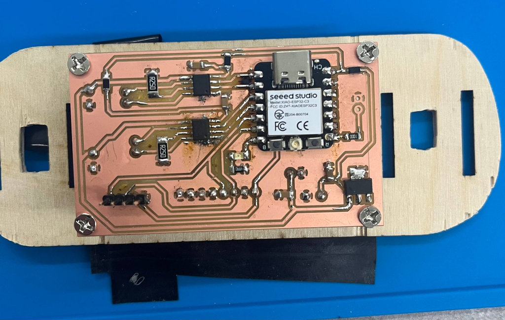
After switching, I did more tests and tuned Kp, Kd, Ki values. I managed to get the robot to balance for a few milliseconds, but realized it’s still not what we need. Also, I still had to finish the PCB responsible for the smile detection part, so we asked Onik for help to stabilize the system.
Here is the final code and video.
#include <Wire.h>
#include <Adafruit_GFX.h>
#include <Adafruit_SSD1306.h>
#include <MPU6050.h>
#include <Arduino.h>
#include "esp32-hal-ledc.h"

// OLED settings
#define SCREEN_WIDTH 128
#define SCREEN_HEIGHT 64
#define OLED_ADDR 0x3C

//MOTORS
// Motor A
#define INA1 2
#define INA2 3

// Motor B
#define INB1 4
#define INB2 5

//debug settings
//#define display_on
#define Serial_on
#define MOTORS
#define PID

Adafruit_SSD1306 display(SCREEN_WIDTH, SCREEN_HEIGHT, &Wire, -1);
MPU6050 mpu(0x69);

// I2C pins
#define SDA_PIN 6
#define SCL_PIN 7


#define PWM_FREQ 1000
#define PWM_RESOLUTION 8

#define CH_A1 0
#define CH_A2 1
#define CH_B1 2
#define CH_B2 3

// Complementary filter variables
float angleX = 0;
float angleY = 0;
float pitch = 0;

//Calibration variables
float gyroX_offset = 0;
float gyroY_offset = 0;
float gyroZ_offset = 0;

float accX_offset = 0;
float accY_offset = 0;
float accZ_offset = 0;

//PID VARS               //////////////////////////////////////
float Kp = 20;
float Ki = 0.5;
float Kd = -2;

float setpoint = -3; // upright

float error = 0;
float previous_error = 0;
float integral = 0;
float derivative = 0;

float output = 0;
//////////////////////////////////////////////

int16_t ax, ay, az;
int16_t gx, gy, gz;

unsigned long lastTime = 0;

void setup() {
  Serial.begin(115200);
  delay(2000);

  // Setup PWM channels
  ledcAttach(INA1, PWM_FREQ, PWM_RESOLUTION);
  ledcAttach(INA2, PWM_FREQ, PWM_RESOLUTION);
  ledcAttach(INB1, PWM_FREQ, PWM_RESOLUTION);
  ledcAttach(INB2, PWM_FREQ, PWM_RESOLUTION);


  Wire.setClock(400000);
  Wire.begin(SDA_PIN, SCL_PIN);

  // OLED init
  // if (!display.begin(SSD1306_SWITCHCAPVCC, OLED_ADDR)) {
  //   Serial.println("OLED not found");
  //   while (1);
  // }

  // display.clearDisplay();
  // display.setTextSize(1);
  // display.setTextColor(WHITE);

  // MPU init
  Serial.println("Initializing MPU6050...");
  mpu.initialize();

  // if (!mpu.testConnection()) {
  //   Serial.println("MPU6050 connection failed");

  //   display.setCursor(0, 0);
  //   display.println("MPU FAIL");
  //   display.display();
  //   while (1);
  // }

  // display.setCursor(0, 0);
  // display.println("MPU OK");
  // display.display();

  // //Calibaration phase
  // // --- Gyro calibration ---
  // display.clearDisplay();
  // display.setCursor(0, 0);
  // display.println("Calibrating...");
  // display.display();

  delay(1000); // let sensor stabilize

  long gx_sum = 0;
  long gy_sum = 0;
  long gz_sum = 0;

  int samples = 1000;

  for (int i = 0; i < samples; i++) {
    int16_t ax, ay, az;
    int16_t gx, gy, gz;

    mpu.getMotion6(&ax, &ay, &az, &gx, &gy, &gz);

    gx_sum += gx;
    gy_sum += gy;
    gz_sum += gz;

    delay(2); // small delay
  }

  // Calculate average offset
  gyroX_offset = gx_sum / (float)samples;
  gyroY_offset = gy_sum / (float)samples;
  gyroZ_offset = gz_sum / (float)samples;

  // Debug
  Serial.println("Gyro offsets:");
  Serial.print(gyroX_offset); Serial.print(" ");
  Serial.print(gyroY_offset); Serial.print(" ");
  Serial.println(gyroZ_offset);

  long ax_sum = 0;
  long ay_sum = 0;
  long az_sum = 0;

  //int samples = 1000;

  for (int i = 0; i < samples; i++) {
    int16_t ax, ay, az;
    int16_t gx, gy, gz;

    mpu.getMotion6(&ax, &ay, &az, &gx, &gy, &gz);

    ax_sum += ax;
    ay_sum += ay;
    az_sum += az;

    delay(2);
  }

  // Calculate offsets
  accX_offset = ax_sum / (float)samples;
  accY_offset = ay_sum / (float)samples;

  // IMPORTANT: Z should be 1g (~16384)
  accZ_offset = (az_sum / (float)samples) - 16384.0;

  Serial.println("Accel offsets:");
  Serial.print(accX_offset); Serial.print(" ");
  Serial.print(accY_offset); Serial.print(" ");
  Serial.println(accZ_offset);
  // display.clearDisplay();
  // display.setCursor(0, 0);
  // display.println("Calibration OK");
  // display.display();

  delay(1000);

  delay(2000);

  lastTime = micros();
}

void loop() {


  // Read raw data
  mpu.getMotion6(&ax, &ay, &az, &gx, &gy, &gz);

  // Time delta
  unsigned long now = micros();
  float dt = (now - lastTime) / 1000000.0;
  lastTime = now;
  if (dt <= 0 || dt > 0.1) return;

  // --- Accelerometer angles (degrees) ---
  //float accAngleX = atan2(ay, az) * 180 / PI;
  float denomX = sqrt(ay * ay + az * az);
  if (denomX < 0.001) denomX = 0.001;

  float accAngleY = atan2(-ax, denomX) * 180 / PI;
  //float accAngleY = atan2(-ax, sqrt(ay * ay + az * az)) * 180 / PI;

  // --- Gyro (convert to deg/sec) ---
  float gyroX = (gx - gyroX_offset) / 131.0;
  float gyroY = (gy - gyroY_offset) / 131.0;

  ax = ax - accX_offset;
  ay = ay - accY_offset;
  az = az - accZ_offset;

  // --- Complementary filter ---
  float alpha = 0.995;
  // if(abs(pitch) < 1)
  //   accAngleY = 0;

  //angleX = alpha * (angleX + gyroX * dt) + (1 - alpha) * accAngleX;
  angleY = alpha * (angleY + (gyroY) * dt) + (1 - alpha) * accAngleY;

  // if(angleY < 0)
  //   pitch = 180 + angleY;
  // else
  //   pitch = angleY - 180;
  // --- Display ---
  if (isnan(angleX) || isnan(angleY)) {
    Serial.println("NaN detected! Resetting...");
    angleX = 0;
    angleY = 0;
    return;
  }
  #ifdef PID
  /// PID LOOP
  error = setpoint - angleY;

  // Integral (with simple limiting)
  integral += error * dt;
  integral = constrain(integral, -100, 100);

  // Derivative
  derivative = -gyroY;//(error - previous_error) / dt;

  // PID output
  output = Kp * error + Ki * integral + Kd * derivative;

  previous_error = error;
  if(abs(angleY) > 45)
    output = 0;


  if (abs(output) < 100 && output != 0) {
    output = (output > 0) ? 100 : -100;
  }
  #endif
  // output += 10;
  // delay(1000);
  #ifdef MOTORS

  int motorSpeed = constrain(abs(output), 0, 250);

  if (output > 0 ) {
    // forward
    ledcWrite(INA1, motorSpeed);
    ledcWrite(INA2, 0);
    ledcWrite(INB1, motorSpeed);
    ledcWrite(INB2, 0);
  } else {
    // backward
    ledcWrite(INA1, 0);
    ledcWrite(INA2, motorSpeed);
    ledcWrite(INB1, 0);
    ledcWrite(INB2, motorSpeed);
  }
  #endif


  #ifdef display_on
  display.clearDisplay();

  display.setCursor(0, 0);
  display.println("MPU6050 Angle");

  // display.setCursor(0, 15);
  // display.print("Angle X: ");
  // display.println(angleX, 2);

  display.print("Angle Y: ");
  display.println(pitch, 2);

  display.display();
  #endif
  #ifdef Serial_on
  Serial.print("output: ");
  Serial.print(output, 2);
  Serial.print(" Angle  Y: ");
  Serial.print(angleY);
  Serial.print(" Kp: ");
  Serial.print(Kp * error);
  Serial.print(" Kd ");
  Serial.print(Kd * derivative);
  Serial.print(" Ki ");
  Serial.println(Ki * integral);
  #endif
  //delay(1);
}
Smile Detection Module
Special thanks to the authors of the wiki.seeedstudio.com documentation for such detailed and easy-to-understand material.
After reading and studying the documentation, one of the key things I realized is that real-time image processing puts a heavy computational load on the chip. Since the ESP32-S3 is mainly designed for face and smile detection, I decided to treat it as a vision co-processor rather than a general-purpose controller.
To achieve maximum stability and performance, I minimized the use of its GPIO connections. Instead of directly controlling all hardware components from the ESP32-S3, I implemented a primary-secondary architecture:
- The Task: The ESP32-S3 focuses entirely on the camera stream and the detection algorithm.
- The Interface: I used only one dedicated output pin (SIGNAL_PIN 43) to communicate with my main microcontroller.
- The Logic: When a smile is confirmed by the algorithm, the ESP32-S3 sends a HIGH signal to the secondary chip, which then handles the rest of the application logic (e.g., triggering motors, displays, or LEDs).
For designing the PCB, I used the following components:
- ESP32-S3
- Voltage Regulator — LM2940
- Required capacitors and resistors
I use only pin 43 to send a HIGH signal to the other chip.
Since I power this controller from the same battery used for the main robot.
Here is the schematic design.
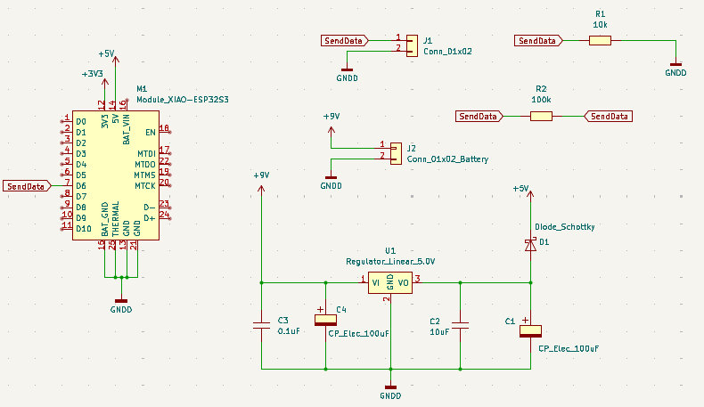
Here is the PCB design.
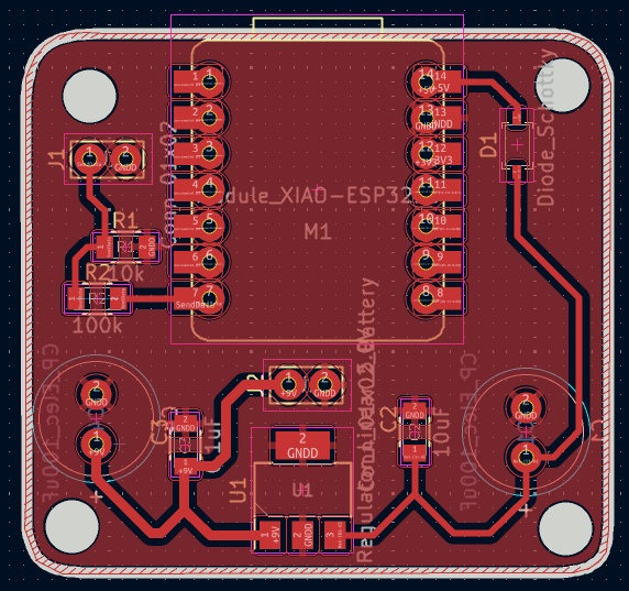
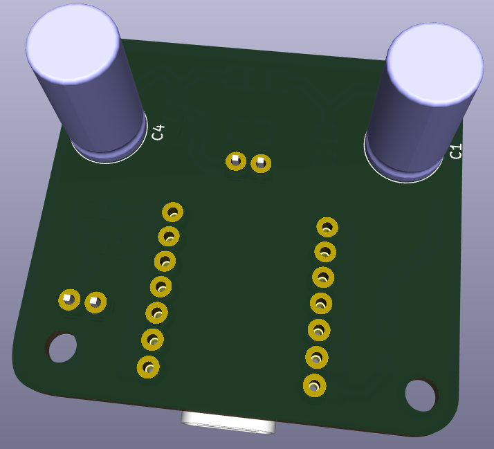
Also, the 3D designs (front and back views).
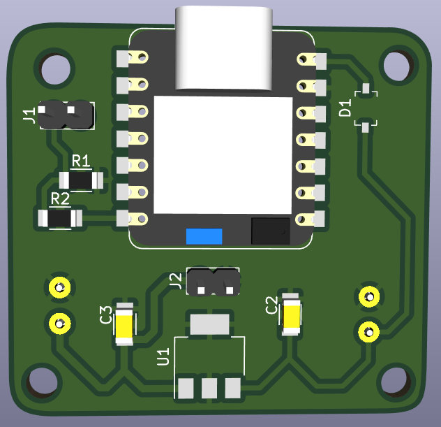
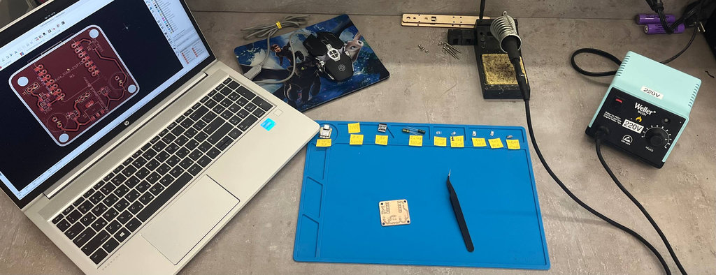
Again, I prepared my workspace for soldering.

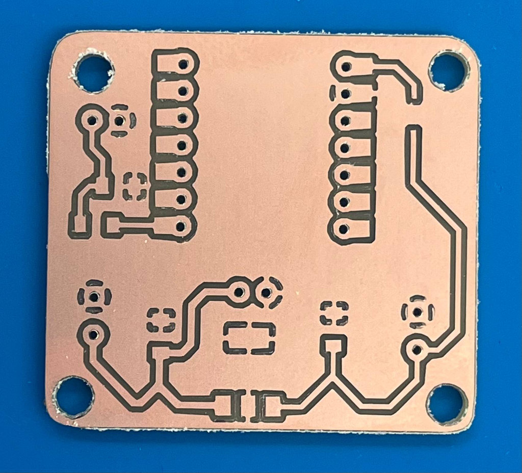
Here is the milled board, as well as the soldered version. I should mention that when attaching the ESP32-S3 to the PCB, I used double-sided tape to prevent the copper layer on the back of the chip from shorting with the PCB GND.
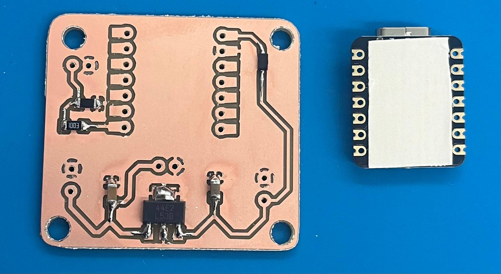
Here is the final result.
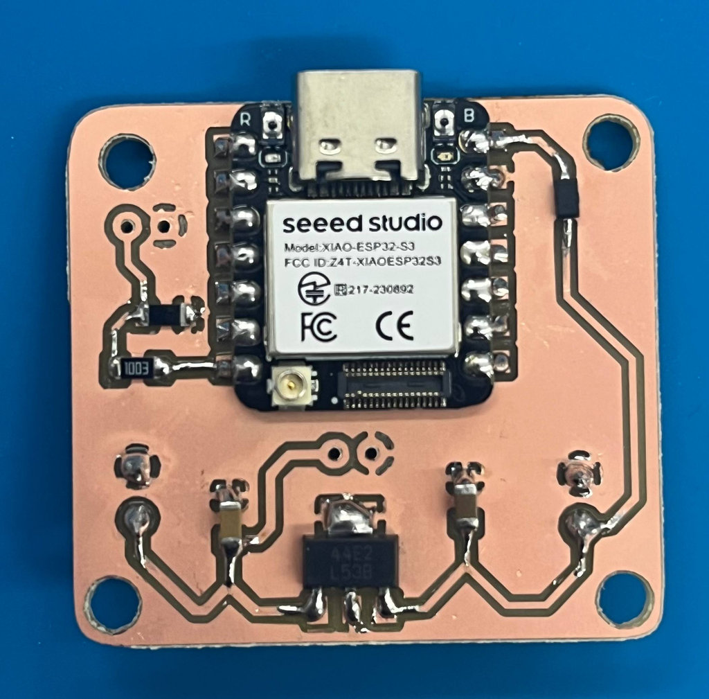
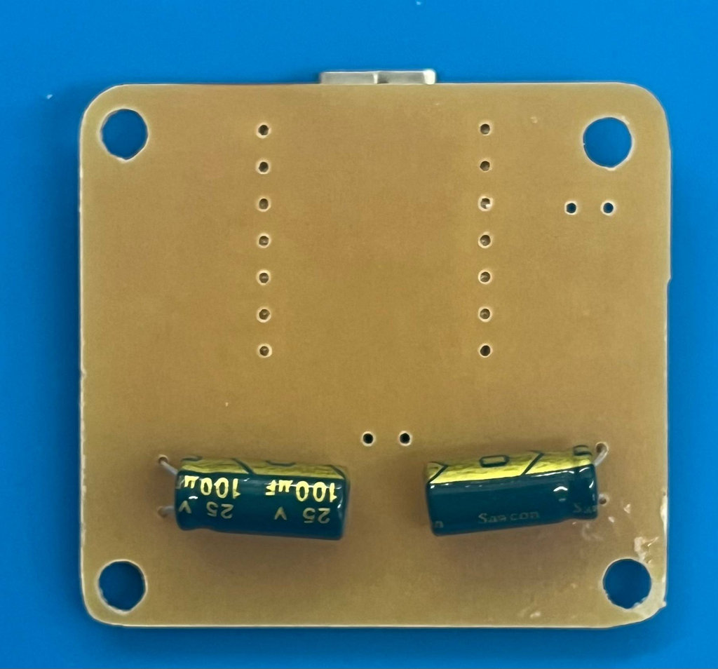
Now let’s move on to programming. The main idea for programming this chip was again taken from wiki.seeedstudio.com, and I also added a small web interface to visualize the results in a nicer way.
#include "esp_camera.h"
#include "Arduino.h"
#include <WiFi.h>
#include <WebServer.h>

// ─── WiFi credentials ───────────────────────────────────────────
#define WIFI_SSID   "iPhone"
#define WIFI_PASS   "Manuela26"

// ─── XIAO ESP32-S3 Sense pinout ─────────────────────────────────
#define CAM_PIN_PWDN  -1
#define CAM_PIN_RESET -1
#define CAM_PIN_XCLK  10
#define CAM_PIN_SIOD  40
#define CAM_PIN_SIOC  39
#define CAM_PIN_D7    48
#define CAM_PIN_D6    11
#define CAM_PIN_D5    12
#define CAM_PIN_D4    14
#define CAM_PIN_D3    16
#define CAM_PIN_D2    18
#define CAM_PIN_D1    17
#define CAM_PIN_D0    15
#define CAM_PIN_VSYNC 38
#define CAM_PIN_HREF  47
#define CAM_PIN_PCLK  13

#define SIGNAL_PIN     43
#define SMILE_HOLD_MS  800   // how long GPIO stays HIGH after smile
#define COOLDOWN_MS   2500   // min time between two smile triggers
#define SMILE_FRAMES     4   // consecutive frames needed to confirm

// ── Relative detection thresholds ───────────────────────────────
// Mouth must be this much brighter than forehead to count as smile
#define RELATIVE_THRESH  22 /// 22
// Local contrast in mouth zone (teeth vs lips boundary)
#define CONTRAST_THRESH  100  ////50

static camera_config_t camera_config = {
  .pin_pwdn      = CAM_PIN_PWDN,  .pin_reset   = CAM_PIN_RESET,
  .pin_xclk      = CAM_PIN_XCLK,
  .pin_sscb_sda  = CAM_PIN_SIOD,  .pin_sscb_scl = CAM_PIN_SIOC,
  .pin_d7=CAM_PIN_D7, .pin_d6=CAM_PIN_D6,
  .pin_d5=CAM_PIN_D5, .pin_d4=CAM_PIN_D4,
  .pin_d3=CAM_PIN_D3, .pin_d2=CAM_PIN_D2,
  .pin_d1=CAM_PIN_D1, .pin_d0=CAM_PIN_D0,
  .pin_vsync=CAM_PIN_VSYNC, .pin_href=CAM_PIN_HREF, .pin_pclk=CAM_PIN_PCLK,
  .xclk_freq_hz  = 10000000,
  .ledc_timer    = LEDC_TIMER_0,
  .ledc_channel  = LEDC_CHANNEL_0,
  .pixel_format  = PIXFORMAT_GRAYSCALE,
  .frame_size    = FRAMESIZE_QVGA,
  .jpeg_quality  = 12,
  .fb_count      = 2,
  .fb_location   = CAMERA_FB_IN_PSRAM,
  .grab_mode     = CAMERA_GRAB_LATEST,
};

WebServer server(80);

int      currentMean        = 0;
int      currentContrast    = 0;
int      currentRelative    = 0;
uint32_t smileHoldUntil     = 0;
uint32_t smileCooldownUntil = 0;
int      consecutiveSmiles  = 0;
uint32_t totalSmiles        = 0;
uint32_t frameCount         = 0;
bool     lastSmileState     = false;
bool     newSmileFlag       = false;

// ────────────────────────────────────────────────────────────────
// RELATIVE smile detection
// Compares mouth zone brightness against forehead zone.
// If the room gets brighter, BOTH zones rise equally → relative
// stays the same → no false trigger.
// Only teeth showing (mouth brighter than forehead) fires a smile.
// ────────────────────────────────────────────────────────────────
bool detectSmile(uint8_t* buf, int w, int h) {

  int colS = w / 4;
  int colE = (w * 3) / 4;

  int foreS = h / 10;
  int foreE = h / 4;

  int mouthS = (h * 62) / 100;
  int mouthE = (h * 85) / 100;

  long sumF=0, cntF=0;
  long sumM=0, cntM=0;
  long globalSum=0;

  int maxM=0, minM=255;

  // --- Global brightness ---
  for (int i=0; i < w*h; i++) globalSum += buf[i];
  int globalMean = globalSum / (w*h);

  // --- Forehead ---
  for (int y=foreS; y < foreE; y++)
    for (int x=colS; x < colE; x++) {
      uint8_t p = buf[y*w+x];
      sumF += p; cntF++;
    }

  // --- Mouth ---
  for (int y=mouthS; y < mouthE; y++)
    for (int x=colS; x < colE; x++) {
      uint8_t p = buf[y*w+x];
      sumM += p; cntM++;

      if (p > maxM) maxM = p;
      if (p < minM) minM = p;
    }

  if (!cntF || !cntM) return false;

  int meanFore  = sumF / cntF;
  int meanMouth = sumM / cntM;

  // --- Normalize against global brightness ---
  int relative  = (meanMouth - meanFore) - (globalMean / 12);

  int contrast  = maxM - minM;

  // --- Face presence check ---
  if (meanFore < 40 || meanFore > 200) return false;

  // --- Dynamic thresholds ---
  int dynamicRelThresh = max(15, meanMouth / 10);
  int dynamicContThresh = max(60, contrast / 2);

  // --- Smooth values (low-pass filter) ---
  static float smoothRel = 0;
  static float smoothCont = 0;

  smoothRel  = 0.7 * smoothRel  + 0.3 * relative;
  smoothCont = 0.7 * smoothCont + 0.3 * contrast;

  currentMean     = meanMouth;
  currentContrast = (int)smoothCont;
  currentRelative = (int)smoothRel;

  bool isSmile = (smoothRel > dynamicRelThresh && smoothCont > dynamicContThresh);

  Serial.printf("Fore:%3d Mouth:%3d Rel:%+3d Cont:%3d ThrR:%d %s\n",
    meanFore, meanMouth,
    (int)smoothRel, (int)smoothCont,
    dynamicRelThresh,
    isSmile ? "<<< SMILE" : "");

  return isSmile;
}

// ─── Web page ───────────────────────────────────────────────────
const char INDEX_HTML[] PROGMEM = R"rawhtml(
<!DOCTYPE html>
<html lang="en">
<head>
<meta charset="UTF-8">
<meta name="viewport" content="width=device-width, initial-scale=1">
<title>Smile Detector</title>
<link href="https://fonts.googleapis.com/css2?family=DM+Mono:wght@400;500&family=Syne:wght@400;700;800&display=swap" rel="stylesheet">
>style>>
*,*::before,*::after{box-sizing:border-box;margin:0;padding:0}
:root{
  --bg:#0a0a0f;--surface:#12121a;--border:#1e1e2e;--muted:#3a3a50;
  --text:#e8e8f0;--subtle:#7070a0;--smile:#c8f060;--neutral:#4060f0;--accent:#f060c0;
}
body{background:var(--bg);color:var(--text);font-family:'Syne',sans-serif;min-height:100vh;display:grid;grid-template-rows:auto 1fr auto;}
body::before{content:'';position:fixed;inset:0;background-image:linear-gradient(var(--border) 1px,transparent 1px),linear-gradient(90deg,var(--border) 1px,transparent 1px);background-size:40px 40px;opacity:0.4;pointer-events:none;z-index:0;}
header{position:relative;z-index:1;padding:1.4rem 2rem;border-bottom:1px solid var(--border);display:flex;align-items:center;justify-content:space-between;}
.grandma-panel { display: flex; justify-content: space-between; position: fixed; top: 150px;width: 100%; }
.grandma-panel img { width: 20%; border-radius: 50%; }
.logo{font-size:1rem;font-weight:800;letter-spacing:0.15em;text-transform:uppercase;color:var(--smile);}
.logo span{color:var(--subtle);font-weight:400;}
.pill{font-family:'DM Mono',monospace;font-size:0.65rem;padding:0.25rem 0.7rem;border-radius:99px;border:1px solid var(--muted);color:var(--subtle);letter-spacing:0.1em;transition:all .3s;}
.pill.online{border-color:var(--smile);color:var(--smile);}
main{position:relative;z-index:1;display:grid;grid-template-columns:1fr 290px;gap:1.2rem;padding:1.2rem 2rem;max-width:1050px;width:100%;margin:0 auto;}
.left{display:flex;flex-direction:column;gap:1.2rem;}
.face{background:var(--surface);border:1px solid var(--border);border-radius:1.4rem;padding:2rem;display:flex;flex-direction:column;align-items:center;gap:1rem;transition:border-color .3s,box-shadow .3s;position:relative;overflow:hidden;}
.face.smiling{border-color:var(--smile);box-shadow:0 0 50px -10px rgba(200,240,96,.3);}
.face::after{content:'';position:absolute;inset:0;background:radial-gradient(ellipse at 50% 0%,rgba(200,240,96,.07) 0%,transparent 70%);opacity:0;transition:opacity .4s;pointer-events:none;}
.face.smiling::after{opacity:1;}
.emoji{font-size:5.5rem;line-height:1;user-select:none;transition:transform .3s cubic-bezier(.34,1.56,.64,1),filter .3s;}
.face.smiling .emoji{transform:scale(1.15);filter:drop-shadow(0 0 18px rgba(200,240,96,.5));animation:pop .45s cubic-bezier(.34,1.56,.64,1);}
@keyframes pop{0%{transform:scale(1)}50%{transform:scale(1.22)}100%{transform:scale(1.15)}}
.slabel{font-size:1.3rem;font-weight:800;letter-spacing:.06em;text-transform:uppercase;color:var(--subtle);transition:color .3s;}
.face.smiling .slabel{color:var(--smile);}
.sigbadge{display:flex;align-items:center;gap:.5rem;font-family:'DM Mono',monospace;font-size:.68rem;color:var(--subtle);padding:.35rem .9rem;border:1px solid var(--muted);border-radius:99px;transition:all .3s;}
.sigbadge.active{color:var(--smile);border-color:var(--smile);background:rgba(200,240,96,.06);}
.dot{width:6px;height:6px;border-radius:50%;background:var(--muted);transition:background .3s;}
.sigbadge.active .dot{background:var(--smile);animation:blink 1s ease-in-out infinite;}
@keyframes blink{0%,100%{opacity:1;transform:scale(1)}50%{opacity:.3;transform:scale(.5)}}
.chart-card{background:var(--surface);border:1px solid var(--border);border-radius:1.3rem;padding:1.2rem 1.3rem;}
.ctitle{font-family:'DM Mono',monospace;font-size:.65rem;letter-spacing:.15em;text-transform:uppercase;color:var(--subtle);margin-bottom:.7rem;}
canvas{width:100%!important;height:90px!important;display:block;}
.tl{font-family:'DM Mono',monospace;font-size:.6rem;color:var(--accent);margin-top:.35rem;opacity:.7;}
.right{display:flex;flex-direction:column;gap:.9rem;}
.sc{background:var(--surface);border:1px solid var(--border);border-radius:1rem;padding:1rem 1.2rem;}
.slb{font-family:'DM Mono',monospace;font-size:.6rem;letter-spacing:.15em;text-transform:uppercase;color:var(--subtle);margin-bottom:.25rem;}
.sv{font-size:1.8rem;font-weight:800;line-height:1;}
.su{font-family:'DM Mono',monospace;font-size:.65rem;color:var(--subtle);margin-top:.15rem;}
.meter{height:3px;background:var(--muted);border-radius:2px;overflow:hidden;margin-top:.5rem;}
.mf{height:100%;border-radius:2px;background:var(--neutral);transition:width .3s,background .3s;}
.mf.hi{background:var(--smile);}
/* Relative meter: negative=blue, positive=green */
.rel-bar-wrap{height:6px;background:var(--muted);border-radius:3px;overflow:hidden;margin-top:.5rem;position:relative;}
.rel-bar{position:absolute;height:100%;border-radius:3px;transition:all .2s;}
.log-card{background:var(--surface);border:1px solid var(--border);border-radius:1rem;padding:1rem 1.2rem;flex:1;display:flex;flex-direction:column;}
.le{font-family:'DM Mono',monospace;font-size:.65rem;line-height:1.9;color:var(--subtle);overflow-y:auto;max-height:300px;}
.lr{display:flex;gap:.6rem;}
.lt{color:var(--muted);flex-shrink:0;}
.es{color:var(--smile);}
footer{position:relative;z-index:1;padding:.8rem 2rem;border-top:1px solid var(--border);display:flex;justify-content:space-between;font-family:'DM Mono',monospace;font-size:.6rem;color:var(--muted);}
@media(max-width:700px){main{grid-template-columns:1fr;padding:1rem;}header,footer{padding:1rem;}}
</style>
</head>
<body>
<header>
  <div class="logo">Smile<span>Detector</span></div>
  <div class="pill" id="pill">CONNECTING...</div>
</header>
<div class="grandma-panel">
 <img src="https://fabacademy.org/2026/labs/dilijan/students/mariam-daghbashyan/images/week_12/Manuela_SmileDetection.jpg" style="transform: scaleX(-1);" class="img-fluid d-flex align-center">
  <img src="https://fabacademy.org/2026/labs/dilijan/students/mariam-daghbashyan/images/week_12/Manuela_SmileDetection.jpg" class="img-fluid d-flex align-center">
</div>
<main>
  <div class="left">
    <div class="face" id="face">
      <div class="emoji" id="emoji">😐</div>
      <div class="slabel" id="slabel">No smile</div>
      <div class="sigbadge" id="sig"><div class="dot"></div><span>GPIO 43 → ESP32-C3</span></div>
    </div>
    <div class="chart-card">
      <div class="ctitle">Relative brightness (mouth − forehead) — last 60 frames</div>
      <canvas id="chart"></canvas>
      <div class="tl">── smile threshold: +22</div>
    </div>
  </div>
  <div class="right">
    <div class="sc">
      <div class="slb">Relative brightness</div>
      <div class="sv" id="v-rel">—</div>
      <div class="su">mouth minus forehead</div>
      <div class="rel-bar-wrap"><div class="rel-bar" id="rel-bar"></div></div>
    </div>
    <div class="sc">
      <div class="slb">Contrast</div>
      <div class="sv" id="v-con">—</div>
      <div class="su">max − min in mouth zone</div>
      <div class="meter"><div class="mf" id="m-con"></div></div>
    </div>
    <div class="sc">
      <div class="slb">Total smiles</div>
      <div class="sv" id="v-total">0</div>
      <div class="su">confirmed this session</div>
    </div>
    <div class="sc">
      <div class="slb">Frames analysed</div>
      <div class="sv" id="v-frames">0</div>
      <div class="su">since boot</div>
    </div>
    <div class="log-card">
      <div class="ctitle">Event log</div>
      <div class="le" id="log"></div>
    </div>
  </div>
</main>
<footer>
  <span>XIAO ESP32-S3 Sense</span>
  <span id="fps">— fps</span>
  <span>Self-balancing robot</span>
</footer>
<script>
const REL_THRESH = 22;
let hist = new Array(60).fill(0);
let lastT = Date.now();
const canvas = document.getElementById('chart');
const ctx = canvas.getContext('2d');

function drawChart() {
  const dpr=devicePixelRatio||1, W=canvas.offsetWidth*dpr, H=90*dpr;
  canvas.width=W; canvas.height=H; ctx.clearRect(0,0,W,H);
  // zero line
  const zy=H/2;
  ctx.strokeStyle='rgba(112,112,160,0.35)';ctx.lineWidth=dpr;
  ctx.beginPath();ctx.moveTo(0,zy);ctx.lineTo(W,zy);ctx.stroke();
  // threshold line
  const range=80, ty=H/2-(REL_THRESH/range)*(H/2);
  ctx.strokeStyle='rgba(240,96,192,0.5)';
  ctx.setLineDash([4*dpr,4*dpr]);
  ctx.beginPath();ctx.moveTo(0,ty);ctx.lineTo(W,ty);ctx.stroke();
  ctx.setLineDash([]);
  // bars
  const bw=W/hist.length;
  hist.forEach((v,i)=>{
    const clamped=Math.max(-range,Math.min(range,v));
    const barH=Math.abs(clamped/range)*(H/2);
    const y=clamped>=0?H/2-barH:H/2;
    ctx.fillStyle=clamped>REL_THRESH?`rgba(200,240,96,${0.5+0.4*(clamped/range)})`:`rgba(64,96,240,${0.3+0.3*(Math.abs(clamped)/range)})`;
    ctx.fillRect(i*bw+1,y,bw-2,barH);
  });
}

async function poll() {
  try {
    const d=await fetch('/data',{cache:'no-store'}).then(r=>r.json());
    const now=Date.now();
    document.getElementById('fps').textContent=Math.round(1000/Math.max(1,now-lastT))+' fps';
    lastT=now;
    const s=d.smile;
    document.getElementById('face').classList.toggle('smiling',s);
    document.getElementById('emoji').textContent=s?'😄':'😐';
    document.getElementById('slabel').textContent=s?'Smile detected!':'No smile';
    document.getElementById('sig').classList.toggle('active',s);
    document.getElementById('v-rel').textContent=(d.relative>=0?'+':'')+d.relative;
    document.getElementById('v-rel').style.color=d.relative>REL_THRESH?'var(--smile)':d.relative>0?'var(--text)':'var(--subtle)';
    document.getElementById('v-con').textContent=d.contrast;
    document.getElementById('v-total').textContent=d.total;
    document.getElementById('v-frames').textContent=d.frames;
    // relative bar: centre=0, right=positive, left=negative
    const rb=document.getElementById('rel-bar');
    const pct=Math.min(50,Math.abs(d.relative)/80*50);
    if(d.relative>=0){rb.style.left='50%';rb.style.width=pct+'%';rb.style.background=d.relative>REL_THRESH?'var(--smile)':'var(--neutral)';}
    else{rb.style.left=(50-pct)+'%';rb.style.width=pct+'%';rb.style.background='var(--accent)';}
    const cm=document.getElementById('m-con');
    cm.style.width=Math.min(100,d.contrast/255*100)+'%';
    cm.classList.toggle('hi',d.contrast>50);
    hist.push(d.relative);
    if(hist.length>60)hist.shift();
    drawChart();
    if(d.new_smile)addLog('Smile confirmed — GPIO 43 HIGH',true);
    document.getElementById('pill').textContent='ONLINE';
    document.getElementById('pill').classList.add('online');
  } catch(e){
    document.getElementById('pill').textContent='OFFLINE';
    document.getElementById('pill').classList.remove('online');
  }
  setTimeout(poll,50);
}

function addLog(msg,smile){
  const el=document.createElement('div');el.className='lr';
  const t=new Date().toTimeString().slice(0,8);
  el.innerHTML=`<span class="lt">${t}</span><span class="${smile?'es':''}">${msg}</span>`;
  const lg=document.getElementById('log');lg.prepend(el);
  while(lg.children.length>50)lg.removeChild(lg.lastChild);
}
addLog('Dashboard connected',false);
poll();
window.addEventListener('resize',drawChart);
</script>
</body>
</html>
)rawhtml";

void handleRoot() { server.send(200,"text/html",INDEX_HTML); }

void handleData() {
  bool smile=(millis()set_brightness(s,1); s->set_contrast(s,1); s->set_saturation(s,-1);
    s->set_whitebal(s,1);   s->set_awb_gain(s,1);
    s->set_exposure_ctrl(s,1); s->set_aec2(s,1);
    s->set_gainceiling(s,GAINCEILING_4X);
  }

  Serial.printf("Connecting to %s",WIFI_SSID);
  WiFi.begin(WIFI_SSID,WIFI_PASS);
  for(int i=0;i<40&&WiFi.status()!=WL_CONNECTED;i++){delay(500);Serial.print(".");}
  if(WiFi.status()==WL_CONNECTED)
    Serial.printf("\n>>> Open: http://%s\n",WiFi.localIP().toString().c_str());
  else
    Serial.println("\nWiFi failed — running headless");

  server.on("/",    handleRoot);
  server.on("/data",handleData);
  server.begin();
  Serial.println("Ready! Watch Rel value — smile when >+22");
}

void loop() {
  server.handleClient();
  digitalWrite(SIGNAL_PIN,millis()buf,fb->width,fb->height);
  esp_camera_fb_return(fb);

  if(smileNow){
    if(++consecutiveSmiles>=SMILE_FRAMES){
      if(millis()>smileCooldownUntil){
        Serial.println(">>> SMILE CONFIRMED");
        smileHoldUntil     =millis()+SMILE_HOLD_MS;
        smileCooldownUntil =millis()+COOLDOWN_MS;
        totalSmiles++;
        newSmileFlag=true;
      }
      consecutiveSmiles=0;
    }
  } else {
    consecutiveSmiles=0;
  }
}
Here is the interface I created.
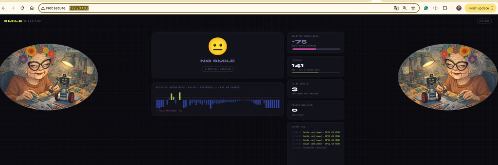
And video
However, the results were not very satisfying. My first approach to smile detection was purely brightness-based, using grayscale pixel analysis without any face detection. The logic compares two zones of the frame: a forehead region (top 10–25% of the frame) as a reference, and a mouth region (62–85% of the frame). If the mouth zone is significantly brighter than the forehead — meaning teeth are visible — and the local contrast in the mouth zone is high enough, the system counts it as a smile.
To make it more robust, I added global brightness normalization, a low-pass smoothing filter on the relative and contrast values, and a face presence sanity check that rejects frames where the forehead brightness is outside the 40–200 range.
However, this approach has a fundamental limitation: it cannot detect smiles accurately because it has no understanding of where the face actually is. The zones are hardcoded as fixed percentages of the full 320×240 frame, which means they only work correctly when the person is centered, at a specific distance, and looking straight at the camera. If the person moves slightly up, down, or sideways, the mouth zone no longer captures the mouth — it may sample the chin, neck, or even the background. The algorithm is essentially detecting brightness patterns in fixed image regions, not actual facial features, which makes it unreliable in real-world conditions where position, distance, and lighting vary.
Person Classification Module
After several unsuccessful attempts and still not achieving good smile detection results, I decided to try something different 😁
I chose to create my own dataset and perform person classification instead of smile detection.
This sounds more complex than smile detection — and after all those failed attempts I probably should have simplified things, not made them harder 😅 — but I’ve always been curious about building ML models, so I couldn’t resist this idea.
And there’s another reason I didn’t give up: the wiki.seeedstudio.com documentation explains everything so clearly and simply that it really motivates you to try it.
Before I could make the robot recognize only me and Hrach, I first needed to create a new machine learning model trained specifically on photos of the two of us. The model would learn from our images and then distinguish between Mariam and Hrach.
To do this, I first needed to build a dataset. Since I had the opportunity not to write everything from scratch, I once again asked AI to write a Python script for me. The script creates folders named Mariam and Hrach inside my existing folder, opens the computer camera, and automatically saves the captured photos into the corresponding folders.
Here is the Python code.
import cv2
import os
import time

# ===== CONFIG =====
people = ["Mariam", "Hrach"]   # <-- persons --> #
dataset_path = "dataset"
images_per_person = 100
img_size = 320

# Load face detector
face_cascade = cv2.CascadeClassifier(
    cv2.data.haarcascades + "haarcascade_frontalface_default.xml"
)

# Create dataset folders
for person in people:
    path = os.path.join(dataset_path, person)
    os.makedirs(path, exist_ok=True)

# Start webcam
cap = cv2.VideoCapture(0)

if not cap.isOpened():
    print("Error: Cannot access camera")
    exit()

print("\nPress 's' to start capturing for each person.")
print("Press 'q' to quit.\n")

for person in people:
    print(f"\n➡️ Get ready for: {person}")
    input("Press ENTER when ready...")

    count = 0
    save_path = os.path.join(dataset_path, person)

    while count < images_per_person:
        ret, frame = cap.read()
        if not ret:
            break

        gray = cv2.cvtColor(frame, cv2.COLOR_BGR2GRAY)

        faces = face_cascade.detectMultiScale(
            gray,
            scaleFactor=1.2,
            minNeighbors=5,
            minSize=(50, 50)
        )

        for (x, y, w, h) in faces:
            face = frame[y:y+h, x:x+w]

            # Resize to 160x160
            face_resized = cv2.resize(face, (img_size, img_size))

            filename = os.path.join(save_path, f"{person}-{count}.jpg")
            cv2.imwrite(filename, face_resized)

            count += 1

            # Draw rectangle
            cv2.rectangle(frame, (x, y), (x+w, y+h), (0,255,0), 2)

            print(f"{person}: {count}/{images_per_person}")

            time.sleep(0.15)  # small delay

            break  # only first face

        cv2.imshow("Dataset Generator", frame)

        if cv2.waitKey(1) & 0xFF == ord('q'):
            break

    print(f"✅ Done for {person}")

cap.release()
cv2.destroyAllWindows()

print("\n🎉 Dataset collection complete!")
I created a folder called PersonClassification-Dataset, which contains another folder named dataset, where this script creates the new Mariam and Hrach folders. The ImageGeneration.py script is also located inside the PersonClassification-Dataset folder.
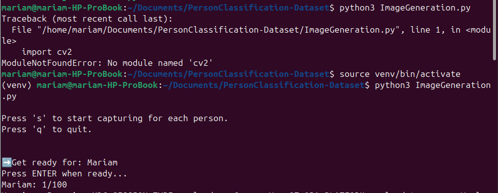
I opened the terminal in the directory where ImageGeneration.py is located and ran the following command:
python3 ImageGeneration.pyAfter running it, the following messages appeared in the terminal:
Press 's' to start capturing for each person.
Press 'q' to quit.
After pressing 's', the following message appears:
Get ready for: Mariam
Press ENTER when ready...
The program waits until I press ENTER. After pressing it, the camera opens and starts taking pictures automatically. After capturing 100 images, the next message appears:
Get ready for: Hrach
Press ENTER when ready...
After pressing ENTER again, it starts capturing Hrach's images as well.
Thank you, Hrach, for your patience and for letting me use your photos. 😄
Now the folders have been created, and the images have been saved into the correct folders.
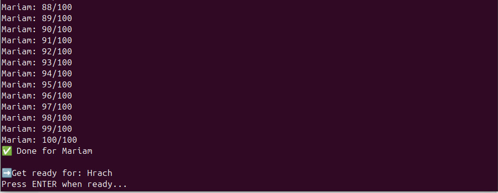
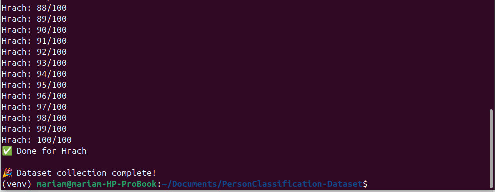
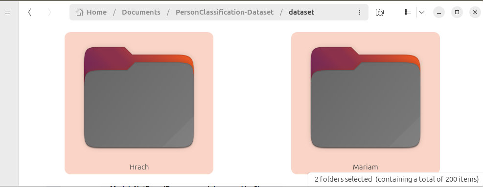
After reading the XIAO ESP32S3-Sense Image Classification documentation, I decided to prepare my own camera model using the Upload images to Edge Impulse Directly workflow.
Everything is explained there in great detail, and I followed exactly the same sequence of steps.
First, I logged into Edge Impulse and created a new project. Then I entered the project and selected:
Data Acquisition → Upload Data → Select Folder

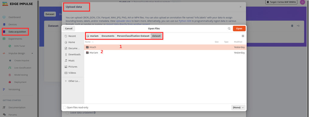
Next, I selected either the Mariam or Hrach folder and used the corresponding label (Mariam or Hrach) depending on which folder I uploaded.
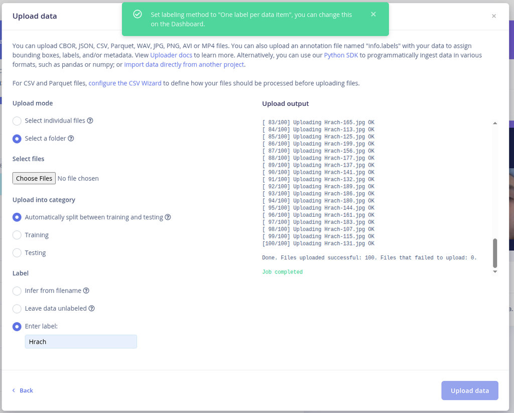
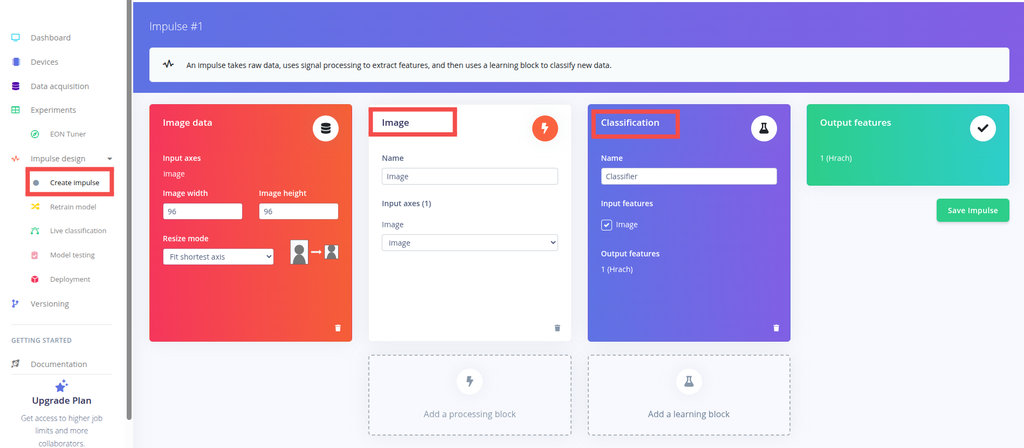
After that, in the Impulse Design section, I selected Create Impulse, chose Image as the input, then selected Classification (Machine learning classification is a supervised learning technique used to predict discrete categories or classes based on input data), and finally clicked Save Impulse.
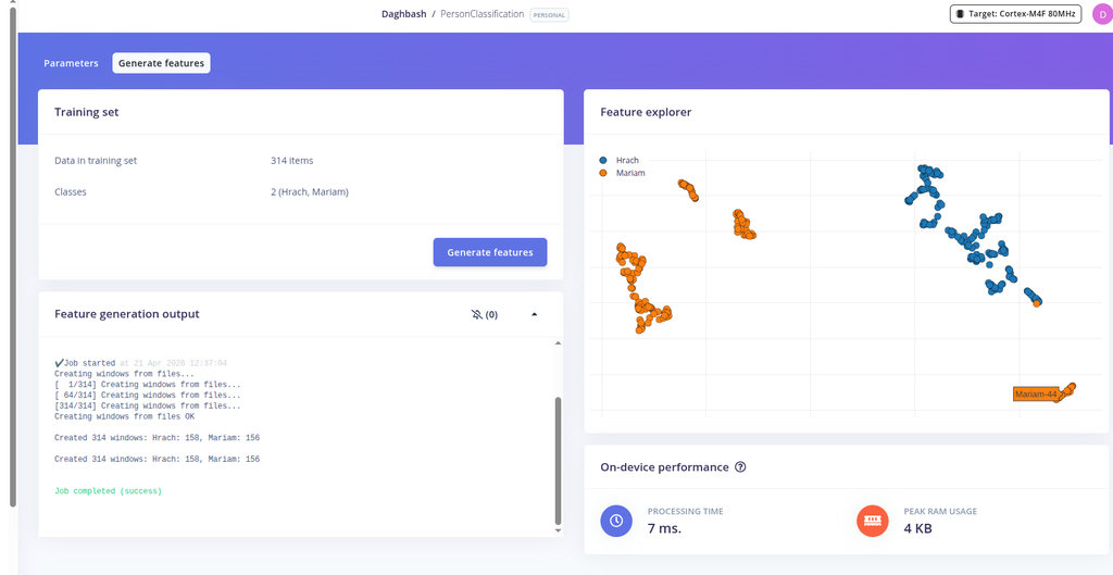
Into Image tab save parameters and go Generate Features tab and generate features.
Next, I opened the Classifier tab and clicked Save and Train.
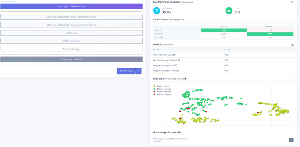
After training finished, I opened the Model Testing section to see how accurately the model could distinguish between me and Hrach.
In this video, you can see that the prediction accuracy reached 91.36%.
The next step was to download this machine learning model and integrate it into Arduino so that it could run directly on the camera.
The Deployment tab in Edge Impulse Studio is used to package the entire machine learning pipeline into a single optimized artifact that can run locally on an edge device without requiring an Internet connection.
In the Deployment tab, I selected Arduino Library as the deployment target and clicked Build. After the process finished, a .zip Arduino library was downloaded to my computer.
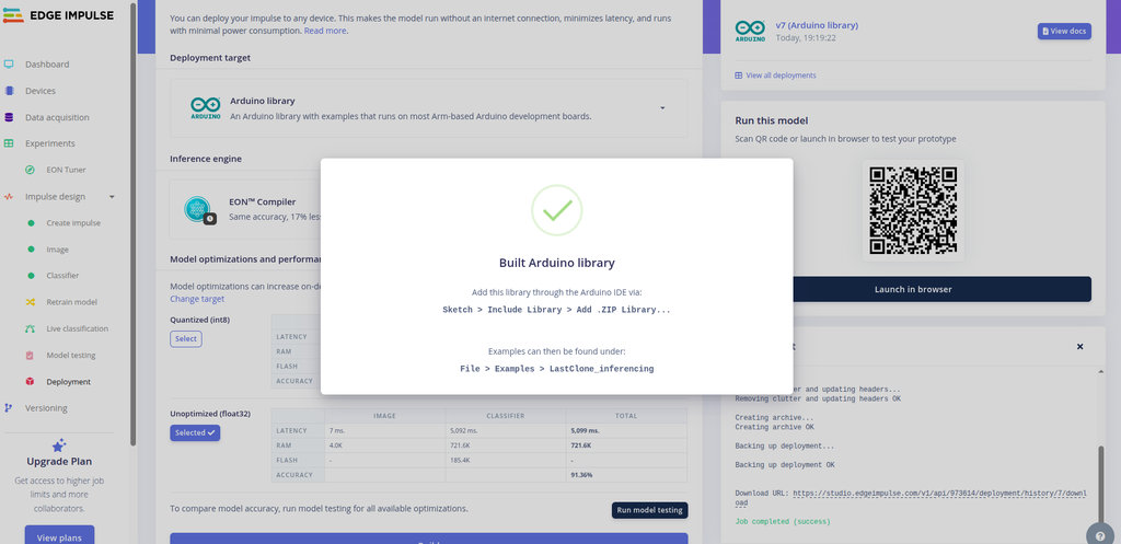
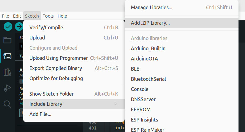
To install it in Arduino, I opened the Arduino IDE and selected:
Sketch → Include Library → Add .ZIP Library...
After the installation finished, a confirmation message appeared at the bottom of the Arduino IDE indicating that the library had been installed successfully.
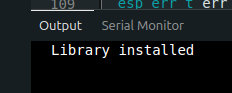
Besides generating the Arduino library, the Deployment page also generates a QR code that allows anyone to open the model on their own device and test it using their phone's camera.
The results were, to put it mildly, quite distorted. I also performed several tests directly on the ESP32-S3, but the results were almost identical to what I had already seen using the QR code.
Oh, it was a very interesting experiment. 😄 Here you can see that the model detects faces so poorly that it recognizes Hrach as Mariam, while almost any other object is recognized as Hrach. This clearly shows that my dataset is far too small. It also proves that I still have absolutely no idea what I'm doing. 😄😄
But honestly, that is exactly why I like these experiments — they make it very obvious where the weaknesses are and what needs to be improved next. 😄
Face detection
So I went back to my original idea—that the camera simply needed to detect that there was a person in front of it, not recognize exactly who that person was. 😄😄
I also generated a separate program for the ESP32-C3 that keeps the robot balanced and receives the signal from the ESP32-S3 so that when a face is detected, the stabilization is disabled.
#include <Wire.h>
#include <Adafruit_GFX.h>
#include <Adafruit_SSD1306.h>
#include <MPU6050.h>
#include <Arduino.h>
#include "esp32-hal-ledc.h"

// OLED settings
#define SCREEN_WIDTH 128
#define SCREEN_HEIGHT 64
#define OLED_ADDR 0x3C

//MOTORS
// Motor A
#define INA1 2
#define INA2 3

// Motor B
#define INB1 4
#define INB2 5

//debug settings
#define display_on
//#define Serial_on
#define MOTORS
#define PID

Adafruit_SSD1306 display(SCREEN_WIDTH, SCREEN_HEIGHT, &Wire, -1);
MPU6050 mpu(0x69);

// I2C pins
#define SDA_PIN 6
#define SCL_PIN 7


#define PWM_FREQ 1000
#define PWM_RESOLUTION 8

#define CH_A1 0
#define CH_A2 1
#define CH_B1 2
#define CH_B2 3

#define FACE_SIGNAL_PIN 10

// Complementary filter variables
float angleX = 0;
float angleY = 0;
float pitch = 0;

//Calibration variables
float gyroX_offset = 0;
float gyroY_offset = 0;
float gyroZ_offset = 0;

float accX_offset = 0;
float accY_offset = 0;
float accZ_offset = 0;

//PID VARS               //////////////// //////////////////////
float Kp = 200;
float Ki = 0;
float Kd = -15;

float setpoint = -2.5; // upright

float error = 0;
float previous_error = 0;
float integral = 0;
float derivative = 0;

float output = 0;
//////////////////////////////////////////////

int16_t ax, ay, az;
int16_t gx, gy, gz;

uint8_t display_count = 0;

unsigned long lastTime = 0;

void setup() {
  Serial.begin(115200);
  delay(2000);

  pinMode(FACE_SIGNAL_PIN, INPUT);

  // Setup PWM channels
  ledcAttach(INA1, PWM_FREQ, PWM_RESOLUTION);
  ledcAttach(INA2, PWM_FREQ, PWM_RESOLUTION);
  ledcAttach(INB1, PWM_FREQ, PWM_RESOLUTION);
  ledcAttach(INB2, PWM_FREQ, PWM_RESOLUTION);


  Wire.setClock(100000);
  Wire.begin(SDA_PIN, SCL_PIN);

  //OLED init
  if (!display.begin(SSD1306_SWITCHCAPVCC, OLED_ADDR)) {
    Serial.println("OLED not found");
    while (1);
  }

  display.clearDisplay();
  display.setTextSize(2);
  display.setTextColor(WHITE);

  // MPU init
  Serial.println("Initializing MPU6050...");
  mpu.initialize();

  // if (!mpu.testConnection()) {
  //   Serial.println("MPU6050 connection failed");

  //   display.setCursor(0, 0);
  //   display.println("MPU FAIL");
  //   display.display();
  //   while (1);
  // }

  display.setCursor(0, 0);
  display.println("MPU OK");
  display.display();

  //Calibaration phase
  // --- Gyro calibration ---
  display.clearDisplay();
  display.setCursor(0, 0);
  display.println("Calibrating...");
  display.display();

  delay(1000); // let sensor stabilize

  long gx_sum = 0;
  long gy_sum = 0;
  long gz_sum = 0;

  int samples = 1000;

  for (int i = 0; i < samples; i++) {
    int16_t ax, ay, az;
    int16_t gx, gy, gz;

    mpu.getMotion6(&ax, &ay, &az, &gx, &gy, &gz);

    gx_sum += gx;
    gy_sum += gy;
    gz_sum += gz;

    delay(2); // small delay
  }

  // Calculate average offset
  gyroX_offset = gx_sum / (float)samples;
  gyroY_offset = gy_sum / (float)samples;
  gyroZ_offset = gz_sum / (float)samples;

  // Debug
  Serial.println("Gyro offsets:");
  Serial.print(gyroX_offset); Serial.print(" ");
  Serial.print(gyroY_offset); Serial.print(" ");
  Serial.println(gyroZ_offset);

  long ax_sum = 0;
  long ay_sum = 0;
  long az_sum = 0;

  //int samples = 1000;

  for (int i = 0; i < samples; i++) {
    int16_t ax, ay, az;
    int16_t gx, gy, gz;

    mpu.getMotion6(&ax, &ay, &az, &gx, &gy, &gz);

    ax_sum += ax;
    ay_sum += ay;
    az_sum += az;

    delay(2);
  }

  // Calculate offsets
  accX_offset = ax_sum / (float)samples;
  accY_offset = ay_sum / (float)samples;

  // IMPORTANT: Z should be 1g (~16384)
  accZ_offset = (az_sum / (float)samples) - 16384.0;

  Serial.println("Accel offsets:");
  Serial.print(accX_offset); Serial.print(" ");
  Serial.print(accY_offset); Serial.print(" ");
  Serial.println(accZ_offset);
  // display.clearDisplay();
  // display.setCursor(0, 0);
  // display.println("Calibration OK");
  // display.display();

  delay(1000);

  delay(2000);

  lastTime = micros();
}

// ── Draw the face ─────────────────────────────────────────────────────────────
// angle: negative = tilt left (sad side), positive = tilt right (happy side)
// faceDetected: draws "FACE!" text and excited eyes
void drawFace(float angle, bool faceDetected) {
  display.clearDisplay();

  int cx = 52;   // face center X  (leave right side for text)
  int cy = 32;   // face center Y
  int r  = 28;   // face radius

  // ── Outer circle ─────────────────────────────────────────────────────────
  display.drawCircle(cx, cy, r, WHITE);

  if (faceDetected) {
    // ── Excited eyes (stars / X marks) ───────────────────────────────────
    // Left eye
    display.drawLine(cx-11, cy-10, cx-7,  cy-6,  WHITE);
    display.drawLine(cx-7,  cy-10, cx-11, cy-6,  WHITE);
    // Right eye
    display.drawLine(cx+7,  cy-10, cx+11, cy-6,  WHITE);
    display.drawLine(cx+11, cy-10, cx+7,  cy-6,  WHITE);

    // ── Big open smile (arc) ──────────────────────────────────────────────
    for (int i = -14; i <= 14; i++) {
      int mx = cx + i;
      int my = cy + 10 + (i * i) / 20;   // parabola → smile curve
      display.drawPixel(mx, my,     WHITE);
      display.drawPixel(mx, my + 1, WHITE);  // thicker line
    }

    // ── "FACE!" label on right ────────────────────────────────────────────
    display.setTextSize(1);
    display.setTextColor(WHITE);
    display.setCursor(90, 20);
    display.println("FACE");
    display.setCursor(90, 32);
    display.println("DETC");

  } else {
    // ── Normal eyes (dots) ────────────────────────────────────────────────
    display.fillCircle(cx - 10, cy - 8, 3, WHITE);  // left eye
    display.fillCircle(cx + 10, cy - 8, 3, WHITE);  // right eye

    // ── Tilting mouth ─────────────────────────────────────────────────────
    // angle > 0  → tilt right (left side up)  → slight smile
    // angle < 0  → tilt left  (right side up) → slight frown
    // clamp to ±30 degrees for reasonable tilt
    float clampedAngle = constrain(angle, -30.0, 30.0);

    // mouth is a line from left point to right point
    // tilt = vertical offset based on angle
    int mouthHalfW = 14;       // half-width of mouth
    int mouthY     = cy + 10;  // vertical center of mouth

    // tilt offset: map ±30° → ±8 pixels vertical shift
    int tiltOffset = (int)(clampedAngle * 8.0 / 30.0);

    int x1 = cx - mouthHalfW;
    int y1 = mouthY + tiltOffset;   // left end
    int x2 = cx + mouthHalfW;
    int y2 = mouthY - tiltOffset;   // right end

    // draw mouth as thick line (2px)
    display.drawLine(x1, y1, x2, y2, WHITE);
    display.drawLine(x1, y1+1, x2, y2+1, WHITE);

    // ── Angle value bottom right ──────────────────────────────────────────
    display.setTextSize(1);
    display.setTextColor(WHITE);
    display.setCursor(86, 50);
    display.print(angle, 1);
    display.print((char)247);  // degree symbol
  }

  display.display();
}

void stopMotors() {
  ledcWrite(INA1, 0);
  ledcWrite(INA2, 0);
  ledcWrite(INB1, 0);
  ledcWrite(INB2, 0);
}

void loop() {
  // Read raw data
  mpu.getMotion6(&ax, &ay, &az, &gx, &gy, &gz);

  // Time delta
  unsigned long now = micros();
  float dt = (now - lastTime) / 1000000.0;
  lastTime = now;
  if (dt <= 0 || dt > 0.1) return;

  // --- Accelerometer angles (degrees) ---
  //float accAngleX = atan2(ay, az) * 180 / PI;
  float denomX = sqrt(ay * ay + az * az);
  if (denomX < 0.001) denomX = 0.001;

  float accAngleY = atan2(-ax, denomX) * 180 / PI;
  //float accAngleY = atan2(-ax, sqrt(ay * ay + az * az)) * 180 / PI;

  // --- Gyro (convert to deg/sec) ---
  float gyroX = (gx - gyroX_offset) / 131.0;
  float gyroY = (gy - gyroY_offset) / 131.0;

  ax = ax - accX_offset;
  ay = ay - accY_offset;
  az = az - accZ_offset;

  // --- Complementary filter ---
  float alpha = 0.70;
  // if(abs(pitch) < 1)
  //   accAngleY = 0;

  //angleX = alpha * (angleX + gyroX * dt) + (1 - alpha) * accAngleX;
  angleY = alpha * (angleY + (gyroY) * dt) + (1 - alpha) * accAngleY;

  // if(angleY < 0)
  //   pitch = 180 + angleY;
  // else
  //   pitch = angleY - 180;
  // --- Display ---
  if (isnan(angleX) || isnan(angleY)) {
    Serial.println("NaN detected! Resetting...");
    angleX = 0;
    angleY = 0;
    return;
  }
  #ifdef PID
  /// PID LOOP
  error = setpoint - angleY;

  // Integral (with simple limiting)
  integral += error * dt;
  integral = constrain(integral, -100, 100);

  // Derivative
  derivative = -gyroY;//(error - previous_error) / dt;

  // PID output
  output = Kp * error + Ki * integral + Kd * derivative;

  previous_error = error;
  if(abs(angleY) > 45)
    output = 0;


  if (abs(output) < 50 && output != 0) {
    output = (output > 0) ? 50 : -50;
  }
  #endif
  // output += 10;
  // delay(1000);
  #ifdef MOTORS

  int motorSpeed = constrain(abs(output), 0, 250);

  if (output > 0 ) {
    // forward
    ledcWrite(INA1, motorSpeed);
    ledcWrite(INA2, 0);
    ledcWrite(INB1, motorSpeed);
    ledcWrite(INB2, 0);
  } else {
    // backward
    ledcWrite(INA1, 0);
    ledcWrite(INA2, motorSpeed);
    ledcWrite(INB1, 0);
    ledcWrite(INB2, motorSpeed);
  }
  #endif

  // Replace this:
  //int signal3 = digitalRead(FACE_SIGNAL_PIN);

  //int signal = digitalRead(FACE_SIGNAL_PIN);
  //Serial.println(signal);
  // Serial print only on change
  //if (signal != 1) {
   // lastSignal = signal;
    // Serial.println(signal == 1
    //   ? ">>> PIN20 HIGH — face detected!"
    //   : ">>> PIN20 LOW  — no face");
  //}

  int signal = digitalRead(FACE_SIGNAL_PIN);

  Serial.println(signal == 1
    ? ">>> PIN10 HIGH — face detected!"
    : ">>> PIN10 LOW  — no face");

  if (signal == HIGH) {
    stopMotors();
    integral       = 0;
    previous_error = 0;
    lastTime       = micros();
    return;
  }

  // With this:
  //int raw = digitalRead(FACE_SIGNAL_PIN);   // 0–4095
 // int signal12 = (raw > 2000) ? HIGH : LOW;  // ~1.6V threshold
  //Serial.print("raw: "); Serial.println(raw);  // add this to see the voltage

  // ── Draw face on OLED ────────────────────────────────────────────────────
  drawFace(angleY, signal == HIGH);

  #ifdef display_on
  if(display_count > 200)
  {
    display.clearDisplay();

    display.setCursor(2, 1);
    // display.println("MPU6050 Angle");

    // display.setCursor(0, 15);
    // display.print("Angle X: ");
    // display.println(angleX, 2);

    // display.print("Angle Y: ");
    display.println(angleY, 2);

    display.display();
    display_count = 0;
  }
  display_count++;
  #endif
  #ifdef Serial_on
  Serial.print("output: ");
  Serial.print(output, 2);
  Serial.print(" Angle  Y: ");
  Serial.print(angleY);
  Serial.print(" Kp: ");
  Serial.print(Kp * error);
  Serial.print(" Kd ");
  Serial.print(Kd * derivative);
  Serial.print(" Ki ");
  Serial.println(Ki * integral);
  #endif
  //delay(1);
}
Once again, I asked AI to generate code for a face detection system running on an ESP32-S3 camera module. It continuously captures camera frames, runs two AI face detection models on each frame, and draws green boxes around any detected faces. Whenever a face is detected, it sets PIN 43 HIGH to signal the STM32 microcontroller to stop balancing the robot. If no face is detected for 1.5 seconds, it sets PIN 43 LOW, allowing the robot to resume balancing. It also hosts a small Wi-Fi web page that displays the live camera feed and face detection statistics in real time.
/*
 * Human Face Detector — ESP32S3 Sense  (single-file version)
 * Web interface with live camera + face detection status overlay.
 *
 * Logic:
 *   Face detected → PIN 43 HIGH → STM32 stops / pauses balancing
 *   No face       → PIN 43 LOW  → STM32 continues moving & balancing
 *
 * Wiring:
 *   ESP32S3 PIN 43 ──► STM32 digital input (e.g. PA0)
 *   ESP32S3 GND    ──► STM32 GND
 *
 * Board settings:
 *   Board: XIAO_ESP32S3   |   PSRAM: OPI PSRAM  ← must be enabled!
 */

#include "esp_camera.h"
#include </home/mariam/.arduino15/packages/arduino/hardware/esp32/2.0.18-arduino.5/tools/sdk/esp32s3/include/esp-dl/include/model_zoo/human_face_detect_msr01.hpp>
#include </home/mariam/.arduino15/packages/arduino/hardware/esp32/2.0.18-arduino.5/tools/sdk/esp32s3/include/esp-dl/include/model_zoo/human_face_detect_mnp01.hpp>
#include <WiFi.h>
#include <WebServer.h>

// ── WiFi credentials ──────────────────────────────────────────────────────────
const char* WIFI_SSID     = "iPhone";
const char* WIFI_PASSWORD = "Manuela27";

// ── Signal pin & detection tuning ────────────────────────────────────────────
#define FACE_SIGNAL_PIN    43
#define CONFIDENCE_THRESH  0.7f
#define FACE_HOLD_MS       1500

// ── Camera pins (XIAO ESP32S3 Sense) ─────────────────────────────────────────
#define PWDN_GPIO_NUM  -1
#define RESET_GPIO_NUM -1
#define XCLK_GPIO_NUM  10
#define SIOD_GPIO_NUM  40
#define SIOC_GPIO_NUM  39
#define Y9_GPIO_NUM    48
#define Y8_GPIO_NUM    11
#define Y7_GPIO_NUM    12
#define Y6_GPIO_NUM    14
#define Y5_GPIO_NUM    16
#define Y4_GPIO_NUM    18
#define Y3_GPIO_NUM    17
#define Y2_GPIO_NUM    15
#define VSYNC_GPIO_NUM 38
#define HREF_GPIO_NUM  47
#define PCLK_GPIO_NUM  13

// ─────────────────────────────────────────────────────────────────────────────
// Embedded web page
// Stream: browser polls GET /stream every 50 ms (cache-busted URL) and swaps
//         the <img> src — no persistent MJPEG connection needed.
// Status: polls GET /status every 500 ms for detection overlay.
// ─────────────────────────────────────────────────────────────────────────────
static const char WEB_PAGE_HTML[] PROGMEM = R"rawhtml(
<!DOCTYPE html>
<html lang="en">
<head>
<meta charset="UTF-8">
<meta name="viewport" content="width=device-width, initial-scale=1">
<title>Face Detector — ESP32S3</title>
<style>
  :root {
    --bg:      #0d0d0d;
    --surface: #181818;
    --border:  #2a2a2a;
    --green:   #00e676;
    --red:     #ff1744;
    --text:    #e0e0e0;
    --muted:   #666;
    --font:    'Courier New', monospace;
  }
  * { box-sizing: border-box; margin: 0; padding: 0; }
  body {
    background: var(--bg);
    color: var(--text);
    font-family: var(--font);
    display: flex;
    flex-direction: column;
    align-items: center;
    padding: 24px 16px;
    min-height: 100vh;
    gap: 20px;
  }
  h1 { font-size: 1rem; letter-spacing: 0.2em; text-transform: uppercase; color: var(--muted); }
  #cam-wrap {
    position: relative;
    display: inline-block;
    border: 2px solid var(--border);
    border-radius: 4px;
    overflow: hidden;
    transition: border-color 0.2s;
  }
  #cam-wrap.face-on  { border-color: var(--green); box-shadow: 0 0 20px rgba(0,230,118,.35); }
  #cam-wrap.face-off { border-color: var(--border); }
  #cam-img { display: block; width: 320px; height: 240px; object-fit: cover; background: #111; }
  #face-badge {
    position: absolute; top: 8px; left: 8px;
    padding: 3px 10px; border-radius: 3px;
    font-size: 0.7rem; letter-spacing: 0.15em; font-weight: bold;
    transition: opacity 0.2s;
  }
  #face-badge.visible  { background: var(--green); color: #000; opacity: 1; }
  #face-badge.hidden-b { background: var(--red);   color: #fff; opacity: 0.6; }
  #stats {
    display: grid; grid-template-columns: repeat(2, 1fr);
    gap: 10px; width: 320px;
  }
  .stat {
    background: var(--surface); border: 1px solid var(--border);
    border-radius: 4px; padding: 10px 14px;
    display: flex; flex-direction: column; gap: 4px;
  }
  .stat-label { font-size: 0.65rem; letter-spacing: 0.12em; color: var(--muted); text-transform: uppercase; }
  .stat-value { font-size: 1.25rem; font-weight: bold; }
  .stat-value.on  { color: var(--green); }
  .stat-value.off { color: var(--red); }
  #pin-row {
    display: flex; align-items: center; gap: 10px;
    font-size: 0.75rem; color: var(--muted); letter-spacing: 0.1em;
  }
  #pin-led {
    width: 12px; height: 12px; border-radius: 50%;
    background: var(--red); box-shadow: 0 0 6px var(--red);
    transition: background 0.2s, box-shadow 0.2s;
  }
  #pin-led.high { background: var(--green); box-shadow: 0 0 10px var(--green); }
  footer { font-size: 0.65rem; color: var(--muted); letter-spacing: 0.1em; }
</style>
</head>
<body>
<h1>■ Face Detector</h1>
<div id="cam-wrap" class="face-off">
  <img id="cam-img" alt="camera stream">
  <div id="face-badge" class="hidden-b">NO FACE</div>
</div>
<div id="stats">
  <div class="stat">
    <span class="stat-label">Status</span>
    <span class="stat-value off" id="s-status">CLEAR</span>
  </div>
  <div class="stat">
    <span class="stat-label">Faces now</span>
    <span class="stat-value" id="s-count">0</span>
  </div>
  <div class="stat">
    <span class="stat-label">Total seen</span>
    <span class="stat-value" id="s-total">0</span>
  </div>
  <div class="stat">
    <span class="stat-label">Hold remaining</span>
    <span class="stat-value" id="s-hold">0 ms</span>
  </div>
</div>
<div id="pin-row">
  <div id="pin-led"></div>
  PIN 43 — <span id="pin-val">LOW</span>
</div>
<footer>ESP32S3 · XIAO Sense · QVGA 320x240</footer>
<script>
const camImg = document.getElementById('cam-img');
let streamBusy = false;
function refreshFrame() {
  if (streamBusy) return;
  streamBusy = true;
  const img = new Image();
  img.onload  = () => { camImg.src = img.src; streamBusy = false; };
  img.onerror = () => { streamBusy = false; };
  img.src = '/stream?t=' + Date.now();
}
setInterval(refreshFrame, 50);

const wrap   = document.getElementById('cam-wrap');
const badge  = document.getElementById('face-badge');
const pinLed = document.getElementById('pin-led');
const pinVal = document.getElementById('pin-val');
async function refreshStatus() {
  try {
    const r = await fetch('/status?t=' + Date.now());
    if (!r.ok) return;
    const d = await r.json();
    if (d.face) {
      wrap.className = 'face-on';
      badge.textContent = 'FACE x' + d.count;
      badge.className = 'visible';
      document.getElementById('s-status').textContent = 'DETECTED';
      document.getElementById('s-status').className   = 'stat-value on';
    } else {
      wrap.className = 'face-off';
      badge.textContent = 'NO FACE';
      badge.className = 'hidden-b';
      document.getElementById('s-status').textContent = 'CLEAR';
      document.getElementById('s-status').className   = 'stat-value off';
    }
    document.getElementById('s-count').textContent = d.count;
    document.getElementById('s-total').textContent = d.total;
    document.getElementById('s-hold').textContent  = d.hold_ms + ' ms';
    if (d.pin43) { pinLed.classList.add('high'); pinVal.textContent = 'HIGH'; }
    else         { pinLed.classList.remove('high'); pinVal.textContent = 'LOW'; }
  } catch (_) {}
}
setInterval(refreshStatus, 500);
refreshStatus();
</script>
</body>
</html>
)rawhtml";

// ── Detection models ──────────────────────────────────────────────────────────
static HumanFaceDetectMSR01 faceDetector(0.3f, 0.5f, 10, 0.3f);
static HumanFaceDetectMNP01 faceRefiner(CONFIDENCE_THRESH, 0.3f, 5);

// ── Web server ────────────────────────────────────────────────────────────────
WebServer server(80);

// ── Shared state ──────────────────────────────────────────────────────────────
volatile bool          g_face_detected    = false;
volatile unsigned long g_last_face_ms     = 0;
volatile int           g_face_count       = 0;
volatile unsigned long g_total_detections = 0;

// ── Latest annotated JPEG ─────────────────────────────────────────────────────
static uint8_t* g_frame_buf   = nullptr;
static size_t   g_frame_len   = 0;
static bool     g_frame_ready = false;

// ─────────────────────────────────────────────────────────────────────────────
// Draw a bounding box on an RGB565 frame buffer.
// ─────────────────────────────────────────────────────────────────────────────
static void drawBox(uint16_t* buf, int w, int h,
                    int x0, int y0, int x1, int y1,
                    uint16_t color, int thickness = 3) {
  x0 = max(0, x0); y0 = max(0, y0);
  x1 = min(w - 1, x1); y1 = min(h - 1, y1);
  for (int t = 0; t < thickness; t++) {
    for (int x = x0 + t; x <= x1 - t; x++) {
      if (y0 + t < h) buf[(y0 + t) * w + x] = color;
      if (y1 - t >= 0) buf[(y1 - t) * w + x] = color;
    }
    for (int y = y0 + t; y <= y1 - t; y++) {
      if (x0 + t < w) buf[y * w + (x0 + t)] = color;
      if (x1 - t >= 0) buf[y * w + (x1 - t)] = color;
    }
  }
}

// ─────────────────────────────────────────────────────────────────────────────
// Capture one frame, run detection, annotate, encode JPEG, update globals.
// ─────────────────────────────────────────────────────────────────────────────
bool captureAndProcess() {
  camera_fb_t* fb = esp_camera_fb_get();
  if (!fb) return false;

  auto candidates = faceDetector.infer(
      (uint16_t*)fb->buf, {(int)fb->height, (int)fb->width, 3});
  auto results = faceRefiner.infer(
      (uint16_t*)fb->buf, {(int)fb->height, (int)fb->width, 3}, candidates);

  g_face_count = (int)results.size();

  // Draw green boxes (RGB565 green = 0x07E0) around each detected face
  if (g_face_count > 0) {
    for (auto& face : results) {
      int bx = face.box[0], by = face.box[1];
      int bw = face.box[2], bh = face.box[3];
      drawBox((uint16_t*)fb->buf, fb->width, fb->height,
              bx, by, bx + bw, by + bh, 0x07E0);
    }
    g_last_face_ms = millis();
    g_total_detections++;
  }

  // Encode to JPEG
  if (g_frame_buf) { free(g_frame_buf); g_frame_buf = nullptr; }
  bool ok = frame2jpg(fb, 80, &g_frame_buf, &g_frame_len);
  esp_camera_fb_return(fb);

  if (ok) g_frame_ready = true;
  return ok;
}

// ─────────────────────────────────────────────────────────────────────────────
// Camera initialisation
// ─────────────────────────────────────────────────────────────────────────────
bool initCamera() {
  camera_config_t config;
  config.ledc_channel = LEDC_CHANNEL_0;
  config.ledc_timer   = LEDC_TIMER_0;
  config.pin_d0 = Y2_GPIO_NUM; config.pin_d1 = Y3_GPIO_NUM;
  config.pin_d2 = Y4_GPIO_NUM; config.pin_d3 = Y5_GPIO_NUM;
  config.pin_d4 = Y6_GPIO_NUM; config.pin_d5 = Y7_GPIO_NUM;
  config.pin_d6 = Y8_GPIO_NUM; config.pin_d7 = Y9_GPIO_NUM;
  config.pin_xclk     = XCLK_GPIO_NUM; config.pin_pclk     = PCLK_GPIO_NUM;
  config.pin_vsync    = VSYNC_GPIO_NUM; config.pin_href     = HREF_GPIO_NUM;
  config.pin_sscb_sda = SIOD_GPIO_NUM;  config.pin_sscb_scl = SIOC_GPIO_NUM;
  config.pin_pwdn     = PWDN_GPIO_NUM;  config.pin_reset    = RESET_GPIO_NUM;
  config.xclk_freq_hz = 20000000;
  config.pixel_format = PIXFORMAT_RGB565;
  config.frame_size   = FRAMESIZE_QVGA;
  config.fb_count     = 2;
  config.fb_location  = CAMERA_FB_IN_PSRAM;
  config.grab_mode    = CAMERA_GRAB_LATEST;
  if (esp_camera_init(&config) != ESP_OK) return false;
  sensor_t* s = esp_camera_sensor_get();
  s->set_hmirror(s, 1);
  s->set_brightness(s, 1);
  s->set_saturation(s, 0);
  return true;
}

// ─────────────────────────────────────────────────────────────────────────────
// HTTP handlers
// ─────────────────────────────────────────────────────────────────────────────
void handleRoot() {
  server.send(200, "text/html", WEB_PAGE_HTML);
}

void handleStream() {
  if (!g_frame_ready || !g_frame_buf) {
    server.send(503, "text/plain", "No frame yet");
    return;
  }
  WiFiClient client = server.client();
  client.print("HTTP/1.1 200 OK\r\n");
  client.print("Content-Type: image/jpeg\r\n");
  client.printf("Content-Length: %u\r\n", g_frame_len);
  client.print("Cache-Control: no-cache\r\n");
  client.print("\r\n");
  client.write(g_frame_buf, g_frame_len);
  client.flush();
}

void handleStatus() {
  long rem = (long)FACE_HOLD_MS - (long)(millis() - g_last_face_ms);
  String json = "{";
  json += "\"face\":"    + String(g_face_detected ? "true" : "false") + ",";
  json += "\"count\":"   + String(g_face_count)        + ",";
  json += "\"total\":"   + String(g_total_detections)  + ",";
  json += "\"pin43\":"   + String(digitalRead(FACE_SIGNAL_PIN)) + ",";
  json += "\"hold_ms\":" + String(g_face_detected && rem > 0 ? rem : 0);
  json += "}";
  server.send(200, "application/json", json);
}

void handleDetect() {
  String json = "{\"face_now\":";
  json += String(g_face_count > 0 ? "true" : "false");
  json += ",\"count\":" + String(g_face_count) + "}";
  server.send(200, "application/json", json);
}

// ─────────────────────────────────────────────────────────────────────────────
// setup()
// ─────────────────────────────────────────────────────────────────────────────
void setup() {
  Serial.begin(115200);
  delay(500);

  pinMode(FACE_SIGNAL_PIN, OUTPUT);
  digitalWrite(FACE_SIGNAL_PIN, LOW);

  if (!initCamera()) {
    Serial.println("Camera init failed — halting");
    while (true) delay(1000);
  }
  Serial.println("Camera OK");

  WiFi.begin(WIFI_SSID, WIFI_PASSWORD);
  Serial.print("Connecting to WiFi");
  while (WiFi.status() != WL_CONNECTED) { delay(500); Serial.print("."); }
  Serial.printf("\nReady — open: http://%s\n", WiFi.localIP().toString().c_str());

  server.on("/",       HTTP_GET, handleRoot);
  server.on("/stream", HTTP_GET, handleStream);
  server.on("/status", HTTP_GET, handleStatus);
  server.on("/detect", HTTP_GET, handleDetect);
  server.begin();
}

// ─────────────────────────────────────────────────────────────────────────────
// loop()
// Owns the camera: capture → detect → annotate → encode → update PIN → serve.
// ─────────────────────────────────────────────────────────────────────────────
void loop() {
  captureAndProcess();

  bool signalHigh = (millis() - g_last_face_ms < FACE_HOLD_MS);

  if (signalHigh && !g_face_detected) {
    g_face_detected = true;
    digitalWrite(FACE_SIGNAL_PIN, HIGH);
    Serial.printf("[PIN43 HIGH] Face detected! count=%d\n", g_face_count);
  } else if (!signalHigh && g_face_detected) {
    g_face_detected = false;
    digitalWrite(FACE_SIGNAL_PIN, LOW);
    Serial.println("[PIN43 LOW]  No face — robot resumes");
  }

  server.handleClient();
}
Robot with Interface
After making several modifications to the code, mainly related to the pin assignments, and after many experiments adjusting the stabilization coefficients to achieve the best possible balancing, I obtained the following result. It still does not perform its main task—keeping the robot perfectly balanced—as well as I would like, but considering that I wrote all of this code in just one week, I think there is still plenty of room for improvement.
The remaining implementations related to this robot, including the 3D modelling, precise parameter tuning, and the robot's physics, can be found on our Group Assignment page, which was implemented by Hrach.
During Week 12, I explored machine learning for image classification and face detection using the XIAO ESP32S3 Sense camera.
I learned how to build my own dataset, train and deploy an Edge Impulse model, and integrate it into Arduino.
Although the person classification model was not reliable enough for my project, the process helped me understand the complete machine learning workflow—from data collection to deployment on embedded hardware. In the end, I changed my approach and implemented face detection instead of person recognition, which was a much more practical solution for my self-balancing robot.
This week taught me that experimenting, testing different ideas, and adapting when something doesn't work is an important part of the engineering process.
Individual assignment
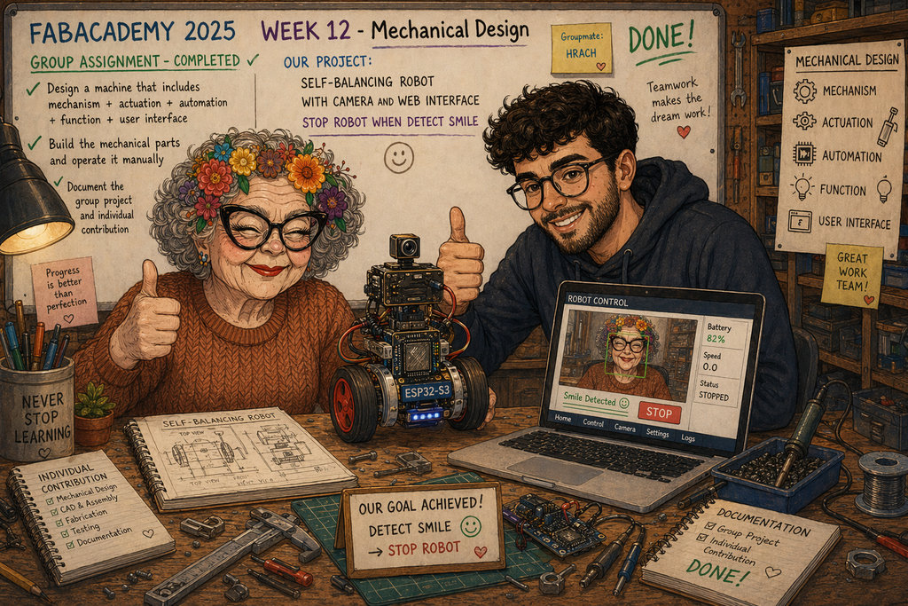
AI prompt:
“And when they finished this week”