
Week 9
AI prompt:
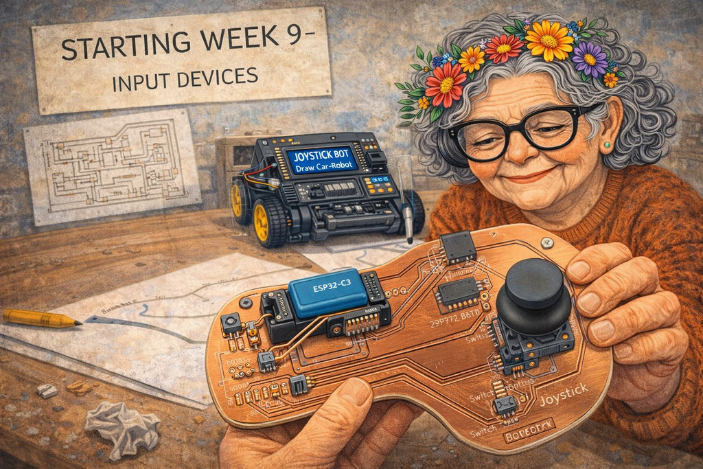
“Now need to generate an image when she started week 9 ''Input Devices''. This week she designed a new PCB like this image. This PCB is for her feature joystick PCB, and this PCB is programmed for Draw Car-Robot. This PCB has an LCD I2C, MCU ESP32C3, Battery, Switch-Button for Battery, and Joystick.”
Input Devices
More details can be found at the Group Assignment link.
As part of the group assignment, Hrach and I ran two experiments at the Dilijan lab — probing a microphone and a colour sensor with the oscilloscope.
Experiment 1 — Microphone on Breadboard
We connected an electret microphone (HMO1003A-65) to a mini breadboard with a 10 kΩ bias resistor and a coupling capacitor, then probed the output with the oscilloscope. When we spoke near the mic, the waveform responded immediately with audio pulses.
The capacitor acts as a high-pass filter — blocking the DC bias and passing only the AC audio signal through to the scope.
Experiment 2 — TCS34725 Colour Sensor + I2C on Oscilloscope
We connected a TCS34725 colour sensor to the Seeed XIAO RP2040 and placed the oscilloscope probes on the SDA and SCL lines to see the I2C communication in real time.
The firmware was written with AI assistance — we asked it to read the sensor, classify the detected colour by hue angle, and output the name, HEX code, and RGB values to Serial Monitor.
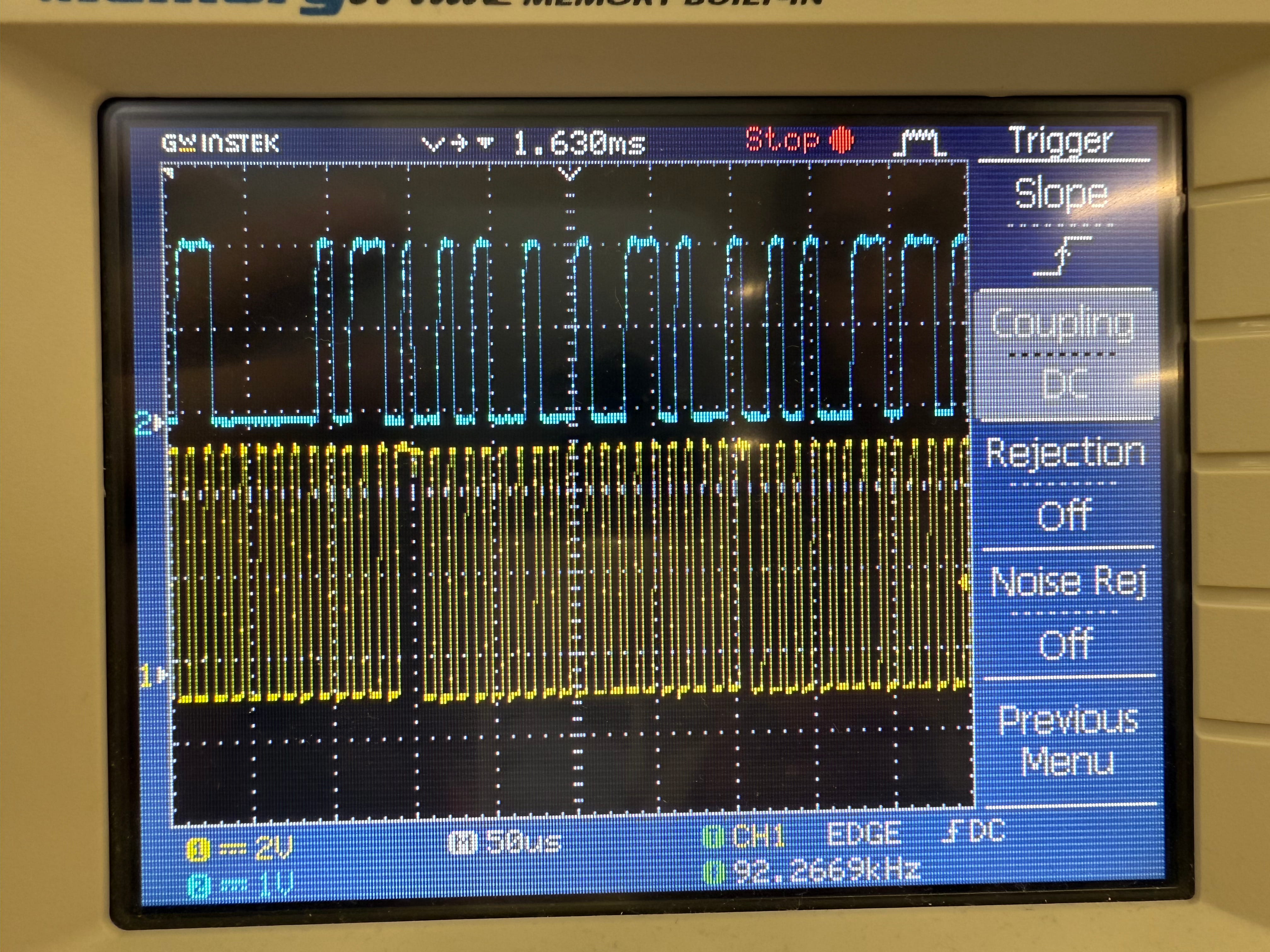
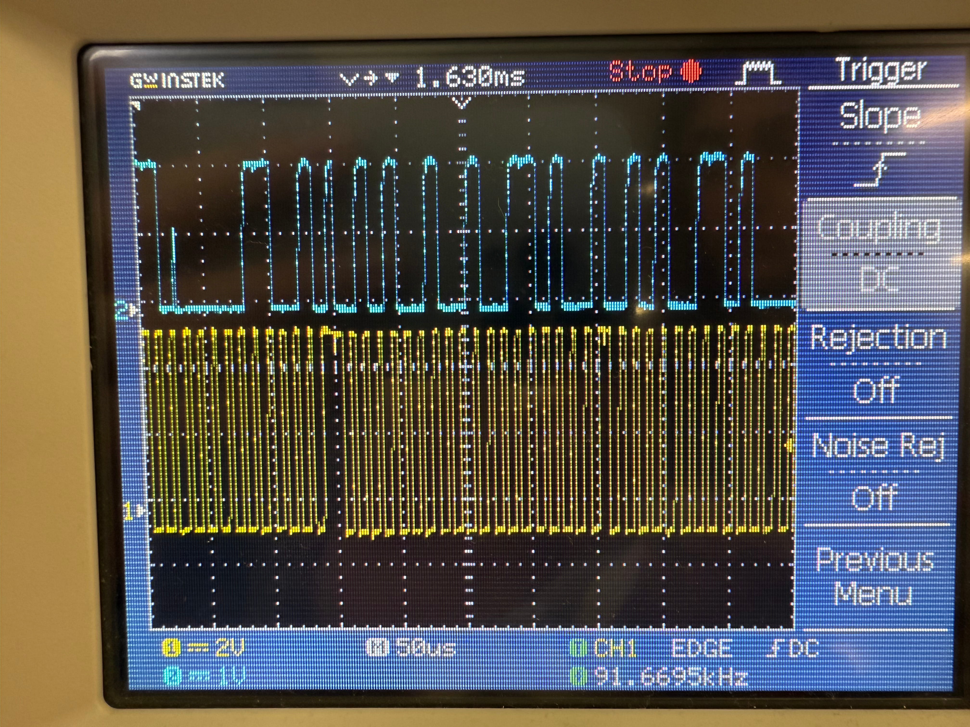
Left: oscilloscope reading when pointing at a red surface | Right: pointing at a white surface
On the oscilloscope we could clearly see two channels:
- CH1 (blue) — SDA: irregular pulses whose pattern changes with each new colour reading
- CH2 (yellow) — SCL: a steady clock signal at
~92 kHz— ticking at the same rate regardless of colour
This made it very clear that digital sensors don't send a simple high/low signal — they send structured data packets at a fixed clock rate. You can literally see different colours produce different bit patterns on SDA.
Since this week is about Input Devices and they need to be included, I will start implementing another part of my Final Project, which also involves the use of input devices. After that, I will try to experiment with other input devices as well.
So, for this week, I planned to design and assemble a new PCB, this time for controlling the car-robot using a joystick.
The joystick system will include the following components:
- Microcontroller –
ESP32-C3 (I switched from RP2040 because this one also has a Wi-Fi system) - Display –
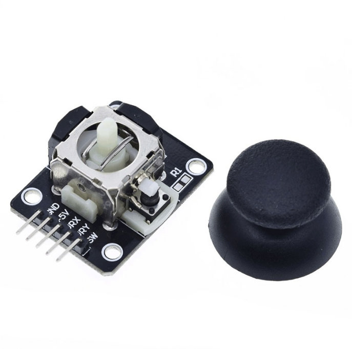
OLED Display (I2C) - Joystick –
standard 5-pin joystick breakout module - Switch Button –
self-locking 6-pin key switch - Battery –
Lithium-ion polymer battery (3.7V, 450mAh) - Led -
LED RED SMD 1206 mini - And some resistors
Before designing my PCB, I explored how a joystick works internally. The joystick contains two potentiometers mounted at 90° to each other. Moving the stick changes the resistance of each potentiometer, producing two analog voltages corresponding to the X and Y axes. The ESP32-C3 converts these voltages into digital values using its 12-bit ADC. A built-in push button provides a digital input when the joystick is pressed.
My used Input Devices and Characteristics:
- Joystick (5-pin breakout module): From the this datasheet
- Type: Analog (X and Y axes) + Digital (Switch).
- Value Range: The X and Y axes use two 10k potentiometers. When powered at 3.3V (standard for ESP32-C3), the resting voltage is roughly 1.65V.
- ADC Reading: With 12-bit resolution (0–4095), the resting value is approximately 2048. Moving the stick varies the output from 0V to VCC.
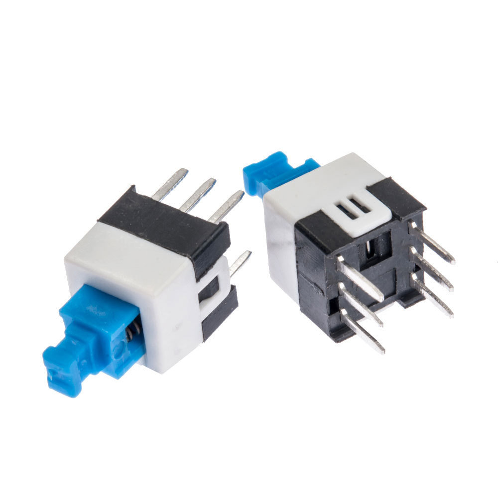
- Switch Button (6-pin self-locking key switch): (From the this youtube link)
- Type: Digital (DPDT - Double Pole Double Throw).
- Value Range: Binary (0 or 1).
- Mechanism: Latching (it stays in the pressed position until pressed again). Since it has 6 pins, it can control two independent circuits simultaneously (e.g., turning on the device and an indicator LED at once).
Purchased from: Amazon
Purchased from: Amazon
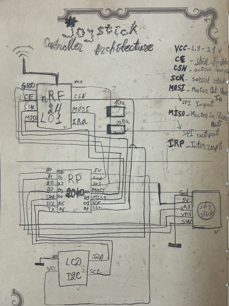
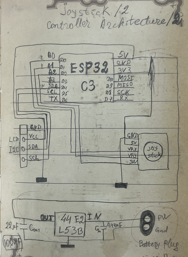
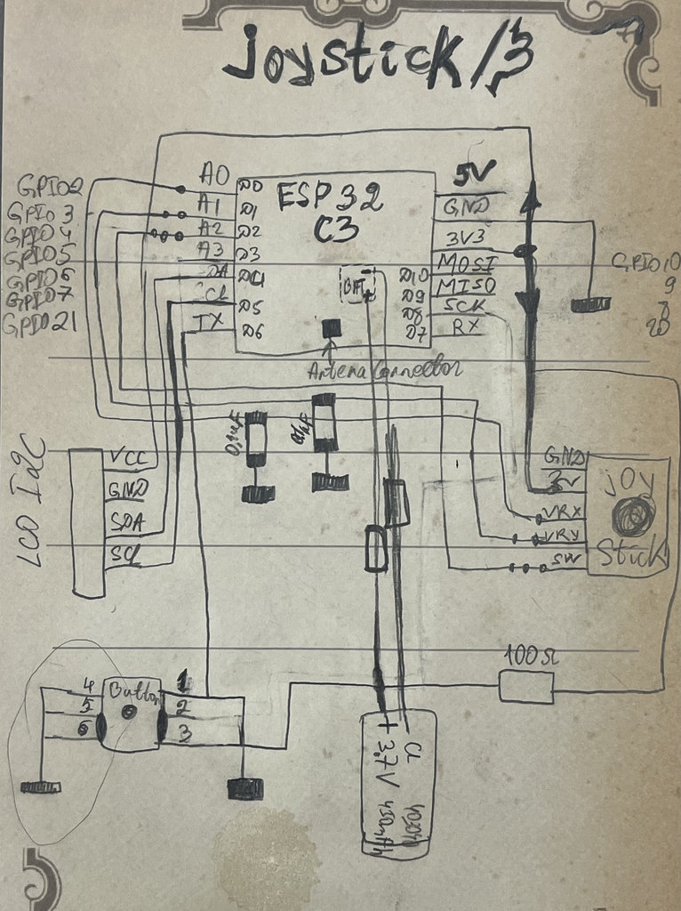
But before getting to the point of selecting the components or even understanding how to properly assemble a joystick, I went through a long research process.
Here are some sketches from my ideas and studies.
Design Rules
- Supply voltage: 3.3 V
- Analog outputs connected to ADC-capable pins
- Keep analog traces short
- Avoid routing analog signals close to noisy digital signals
- Use a common ground
- Add mechanical support around the joystick because it experiences physical force during operation
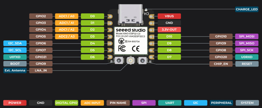
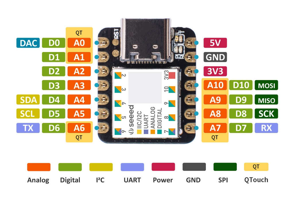
ESP32-C3 pin out diagram
After that, I needed to transfer everything into a digital environment — KiCad.
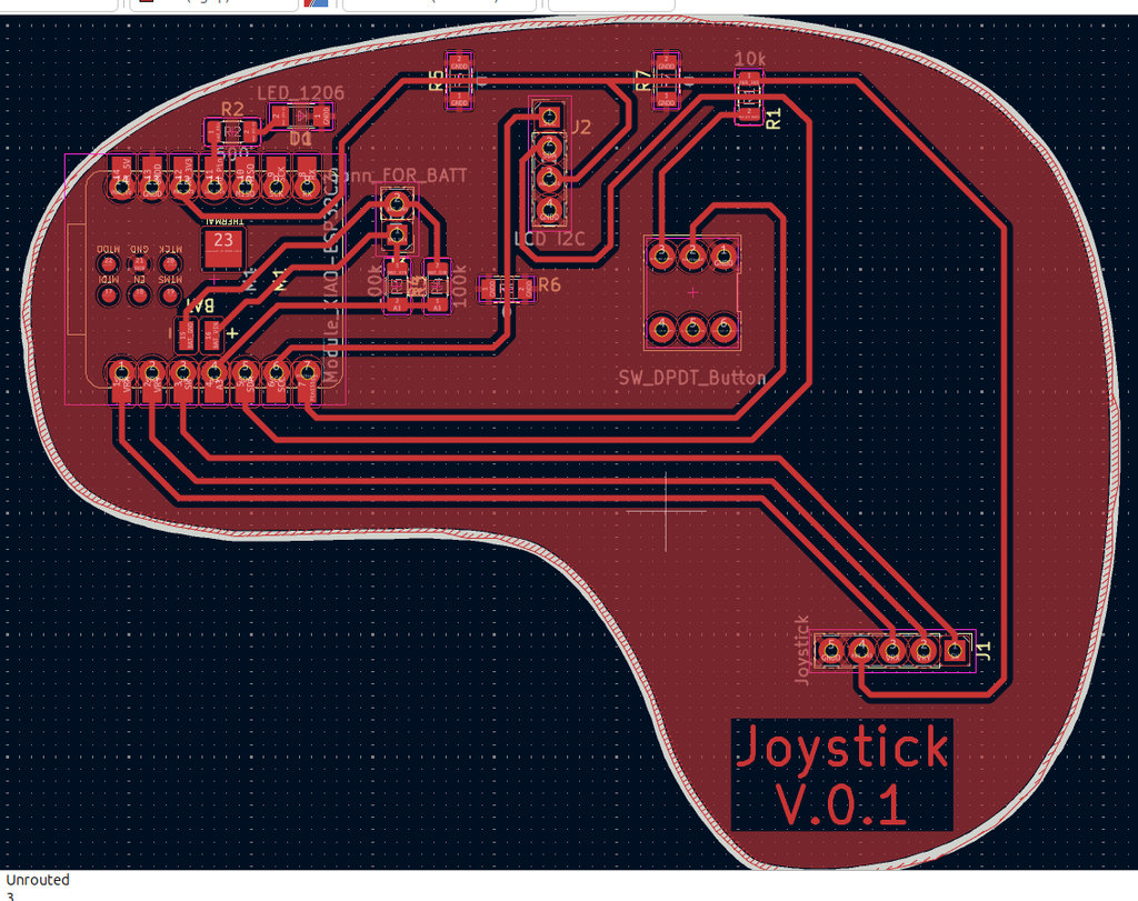
Here is the schematic design, where I already included all the required components.
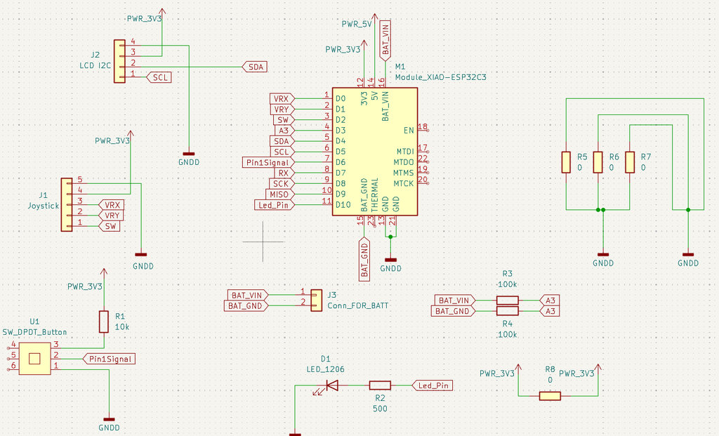
I needed several 0-ohm resistors to properly route the connections, and two 100 kΩ resistors connected from the battery to the appropriate analog pin of the microcontroller in order to measure the battery voltage.
I also used a 500 Ω resistor connected to an LED.
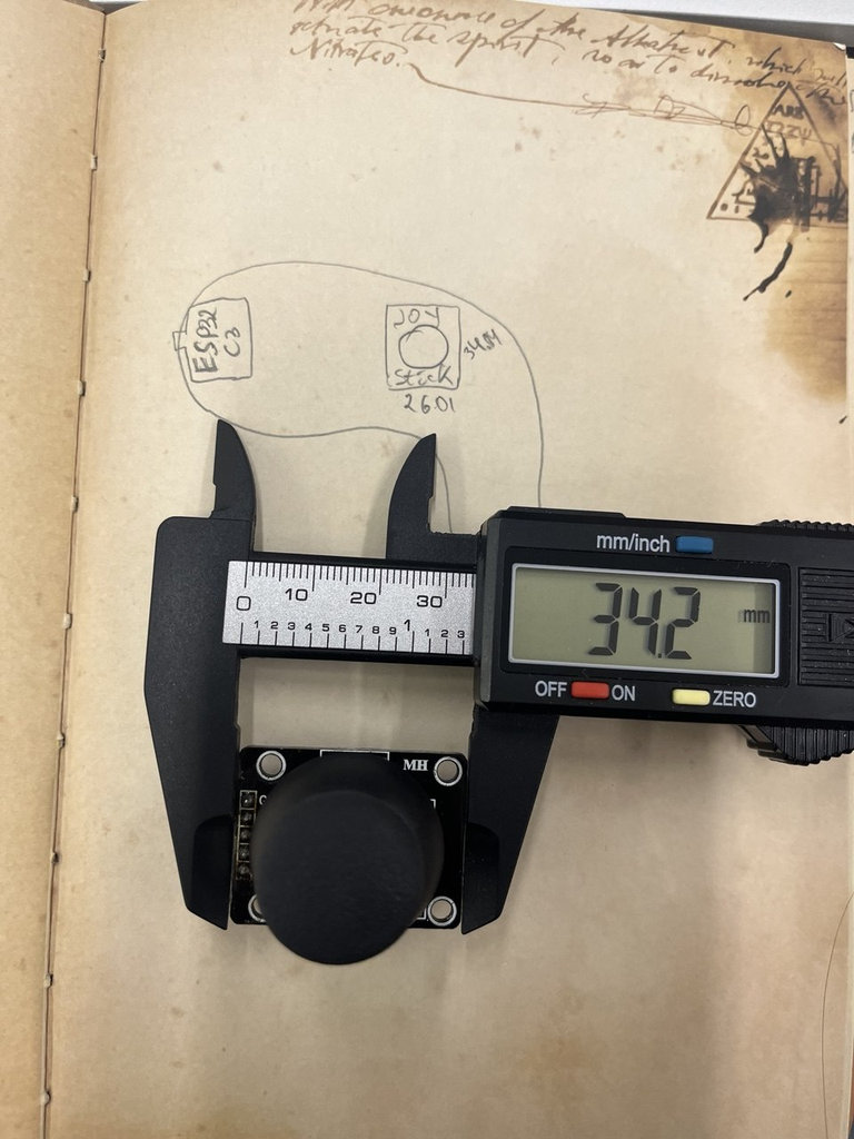
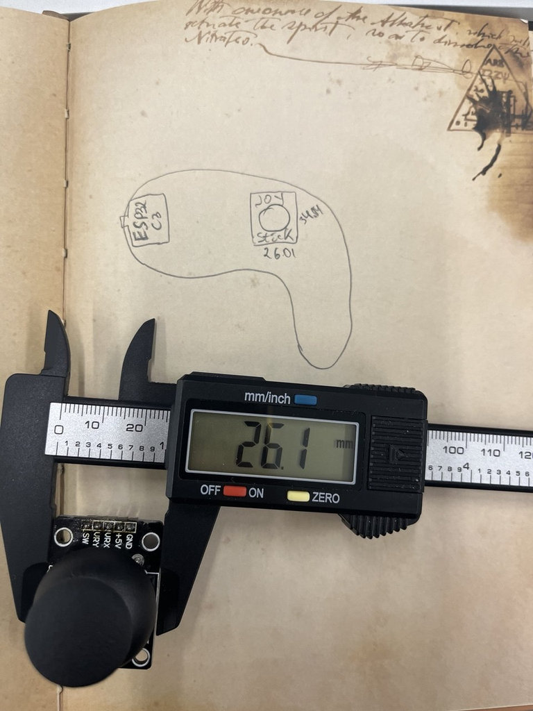
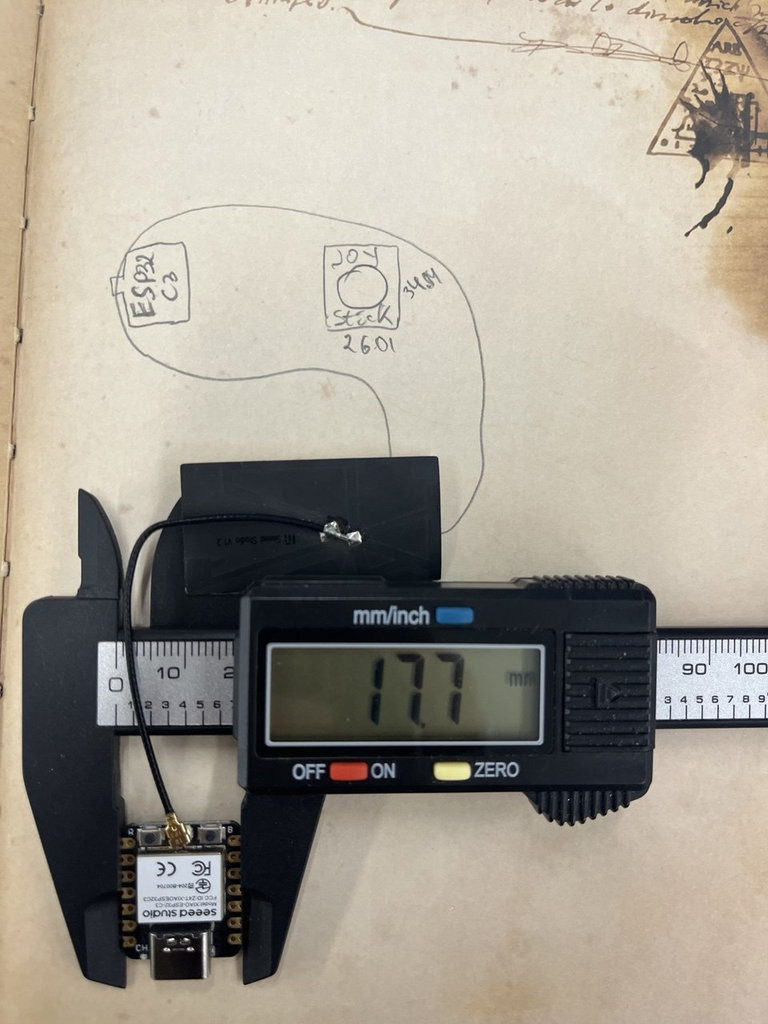
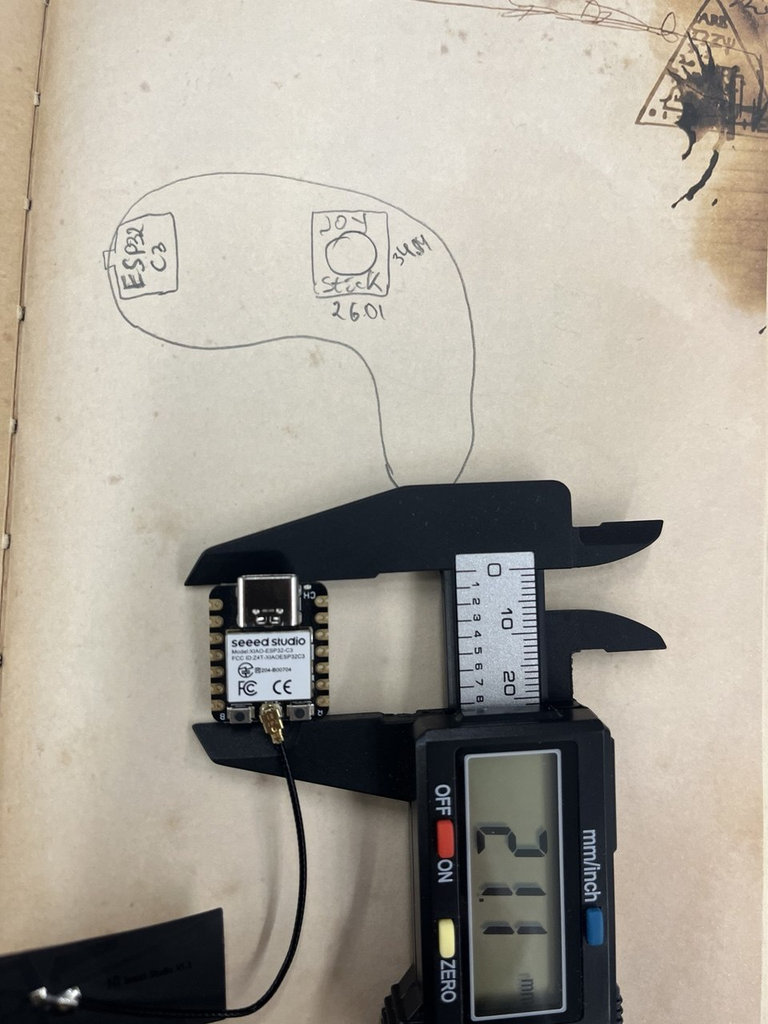
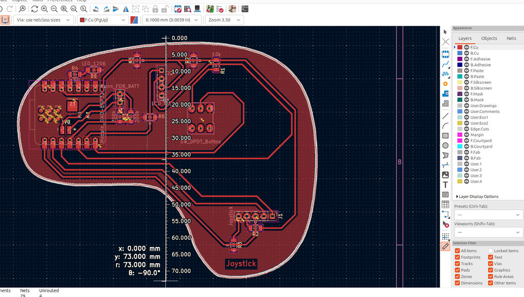
Then, moving on to the PCB design, I initially started with a classic joystick layout, but I decided to add my own style. After a few experiments, I realized that it would be better to use the real dimensions of the components before continuing.
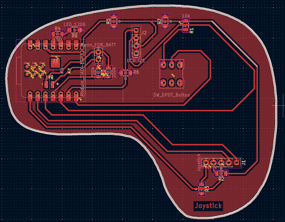
Here is the result.
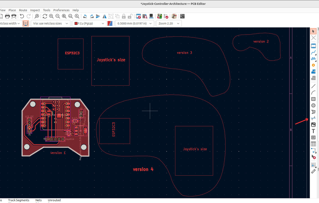
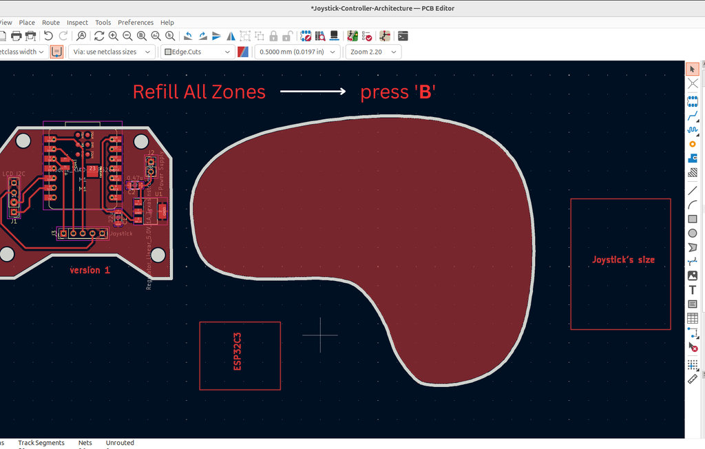
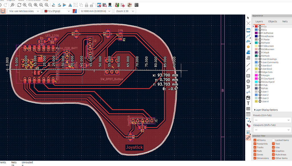
After that, using a very useful tool Draw Bezier Curve, I worked on achieving my preferred design.
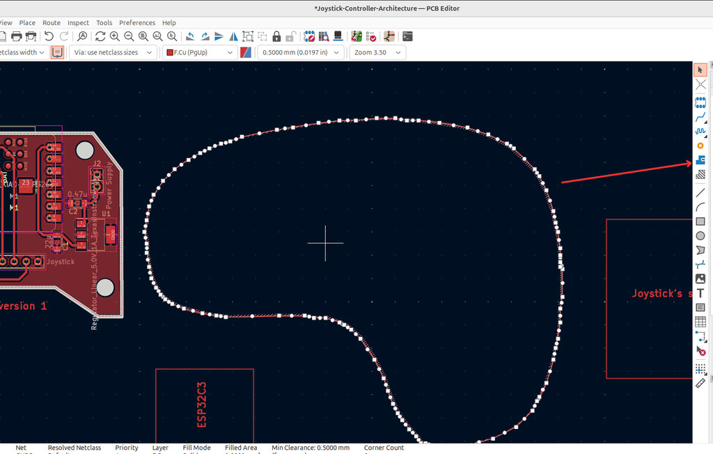
By defining the Edge.Cuts, I started the long and detailed process of assigning the entire area as GND, which was challenging due to the complex curves in my design.
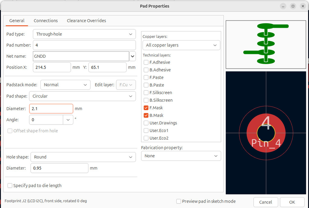
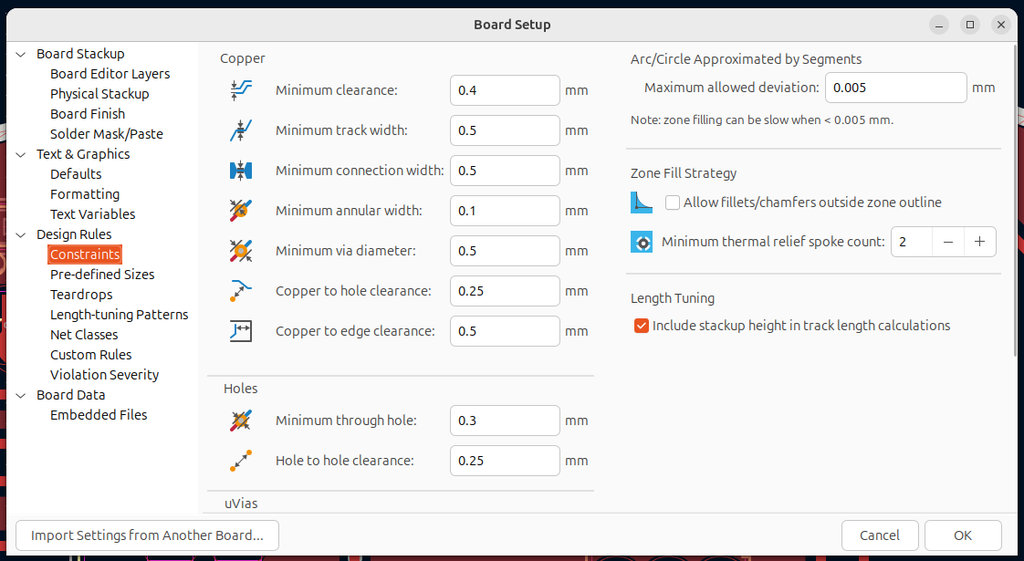
Once the design was complete, I moved on to setting the correct inner and outer diameters of the holes(2.1mm and 0.95mm), as well as adjusting other parameters. I set the clearance values to 0.4mm and the track width to 0.5 mm, connection width 0.5mm.
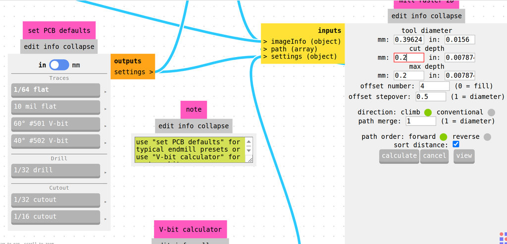
After exporting the SVG files, I generated the G-code in mods, separately for:
- F.Cu (engraving)
- Edge.Cuts (cutting the board and holes)
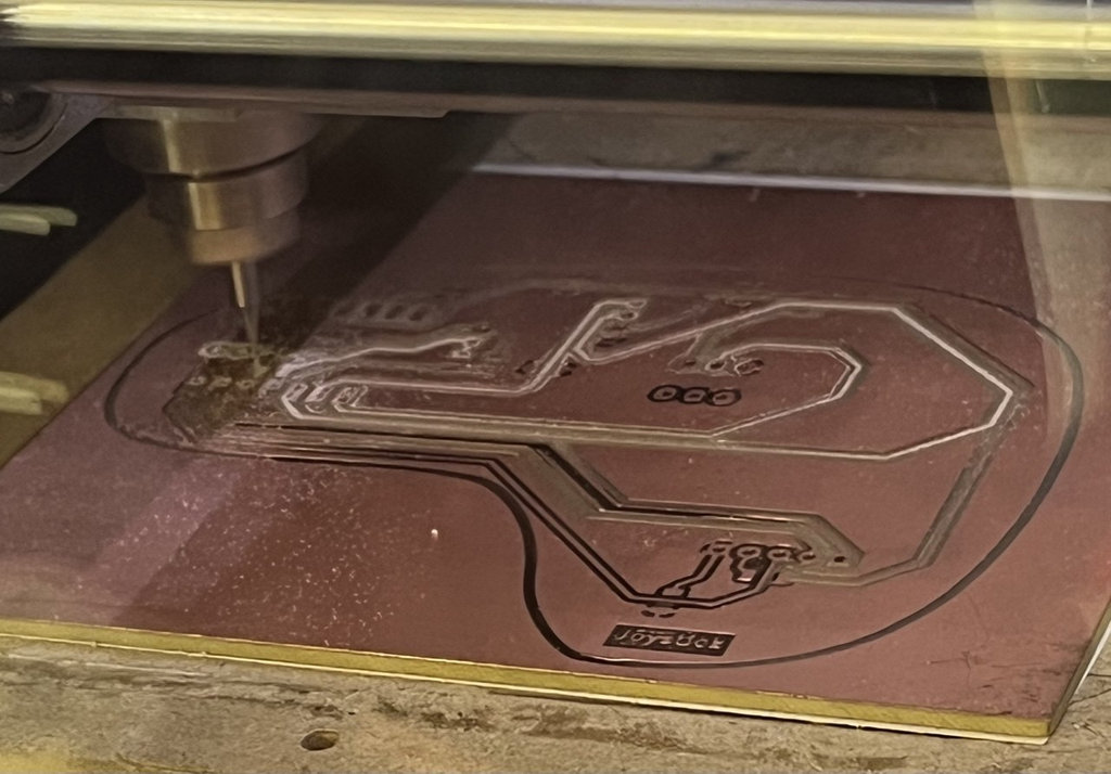
The first attempt failed. As seen in the image, some copper areas remained unengraved.
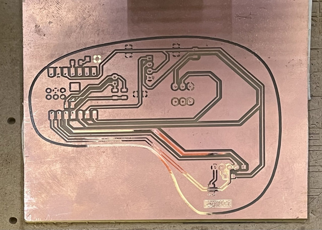
I tried again, thinking the issue was the Z-axis zero position, so I regenerated the G-code and increased the cut depth to 0.2 mm to ensure deeper engraving.
However, as seen in the next result, there was still no engraving in the same area, which was very strange. Since the copper thickness is about 0.1 mm, doubling the cut depth should have worked. This indicated that the issue was not related to the Z-axis.
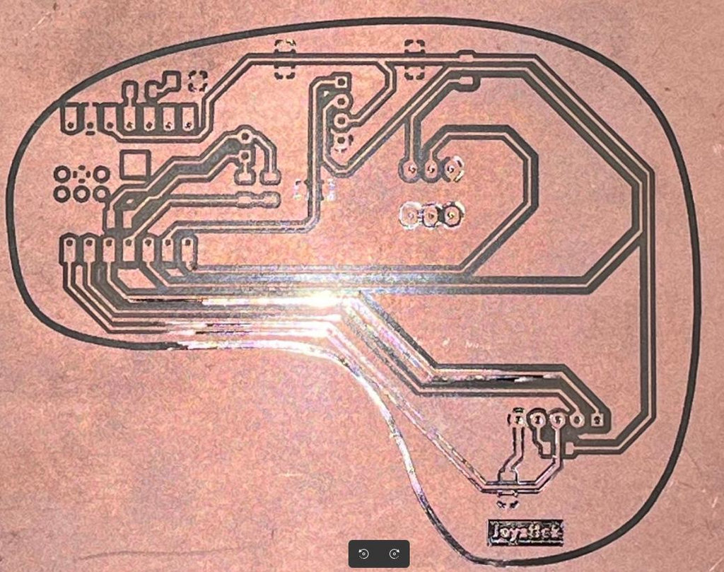
After examining the PCB, we realized that it had a slight curvature, which could cause uneven engraving. It might also be related to material quality or storage conditions.
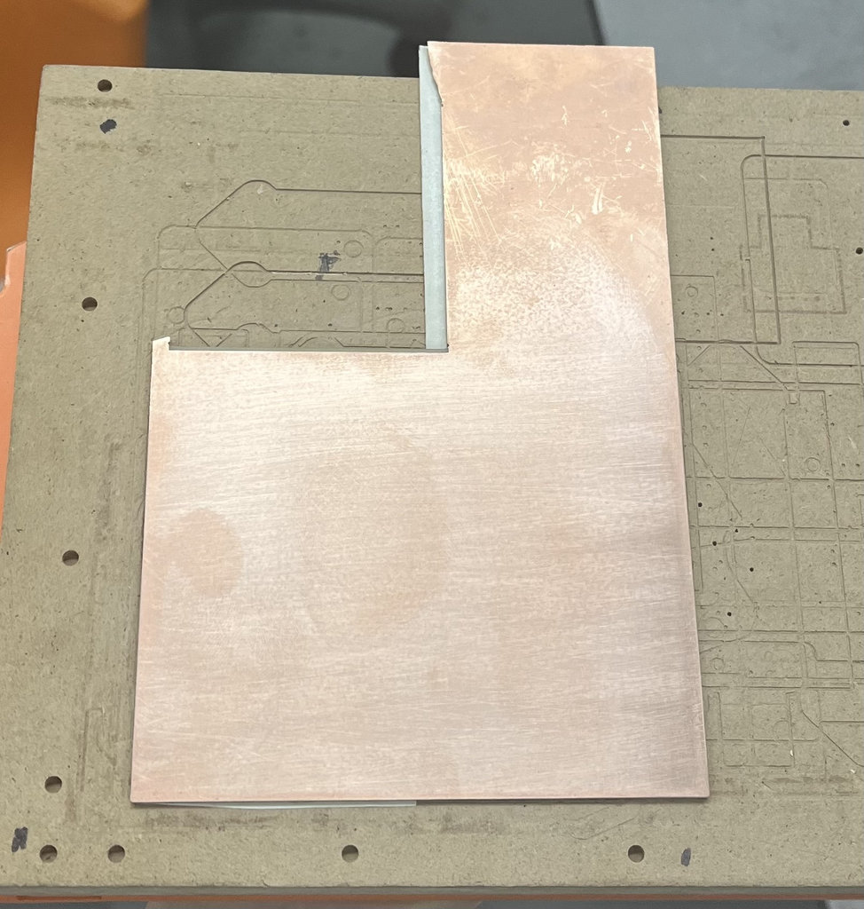
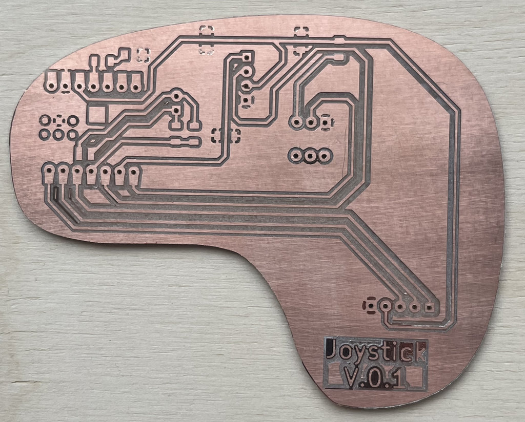
So, I took a new PCB board, cleaned the surface with an alcohol solution, and prepared the copper layer.
Then I fixed it onto the CNC bed, waited about 15 minutes, and started the process again.
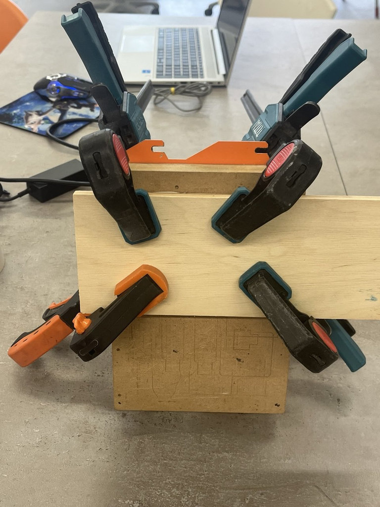
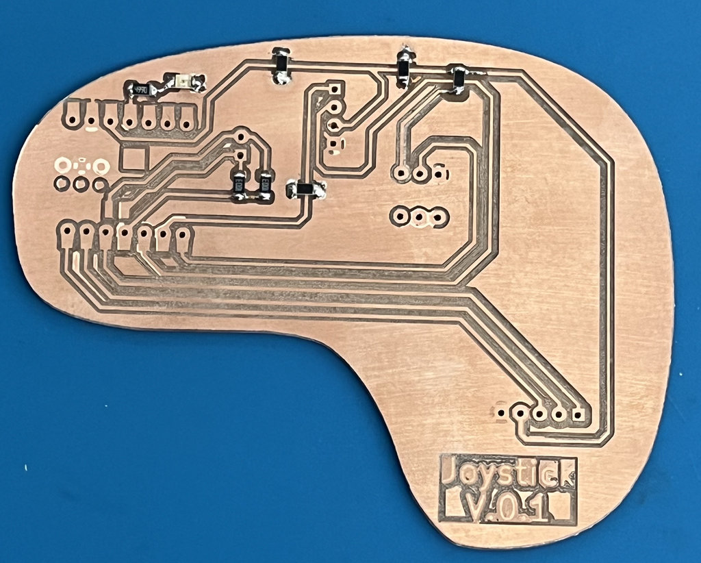
As seen in the image, the engraving process worked correctly.
Now I move on to the long-awaited step 😄 — it’s time for soldering.
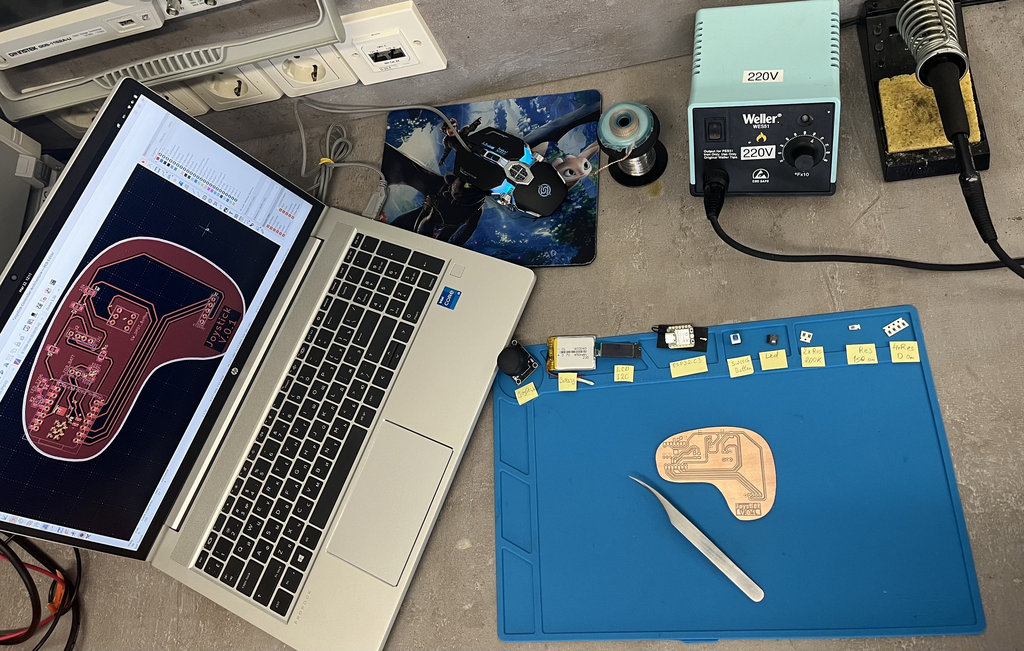
I gathered all the necessary components again to keep the process organized and clean.
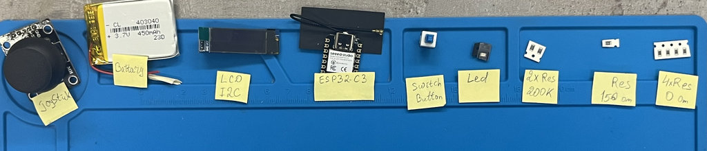
All the small components were already soldered.
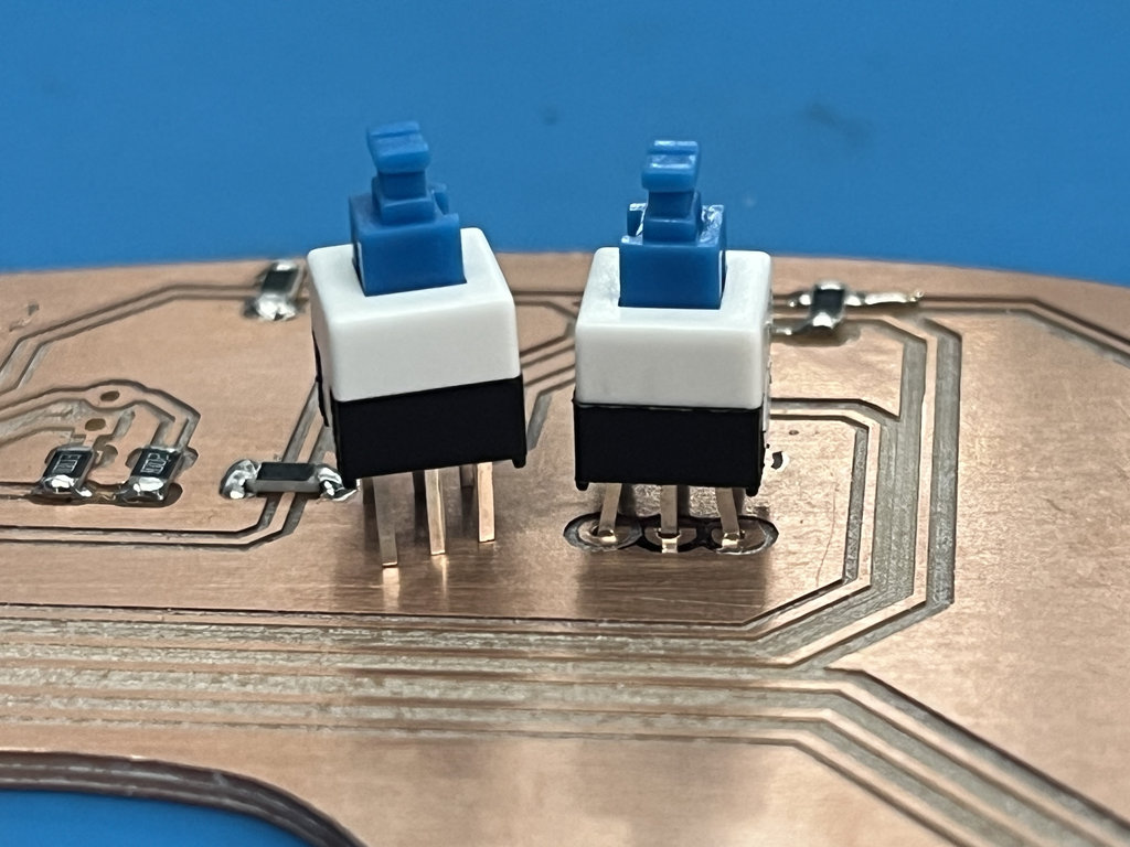
While installing the switch button footprint, I realized that I had downloaded the wrong footprint size, so I had to slightly bend and adjust the pins to fit them properly.
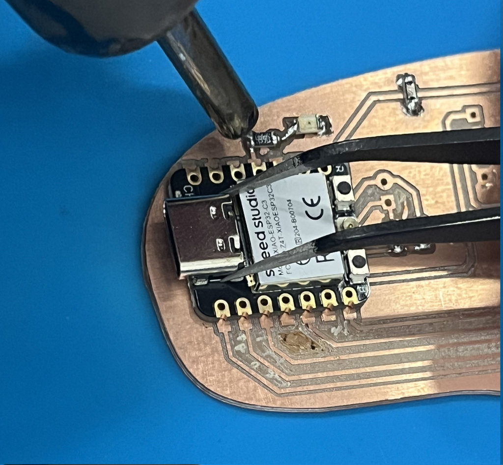
The next challenge was securely attaching the MCU to the PCB. After soldering a few points with solder wire, I used a Hot Air Rework Station to melt and properly fix it in place. I also cleaned small unnecessary copper traces to avoid potential short circuits in the future.
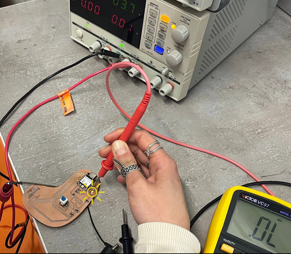
To verify that the MCU was soldered correctly, I wrote a simple code to turn on an LED. This helped me confirm that BAT+ and BAT− connections were correct. However, instead of connecting the battery directly, I used a Power Supply to provide 3.7V to the battery pads using two wires.
Here is the code and the working LED.
void setup() {
  pinMode(10, OUTPUT);
  digitalWrite(10, HIGH); // Turns on as soon as the code starts
}

void loop() {
  // Stay on
}
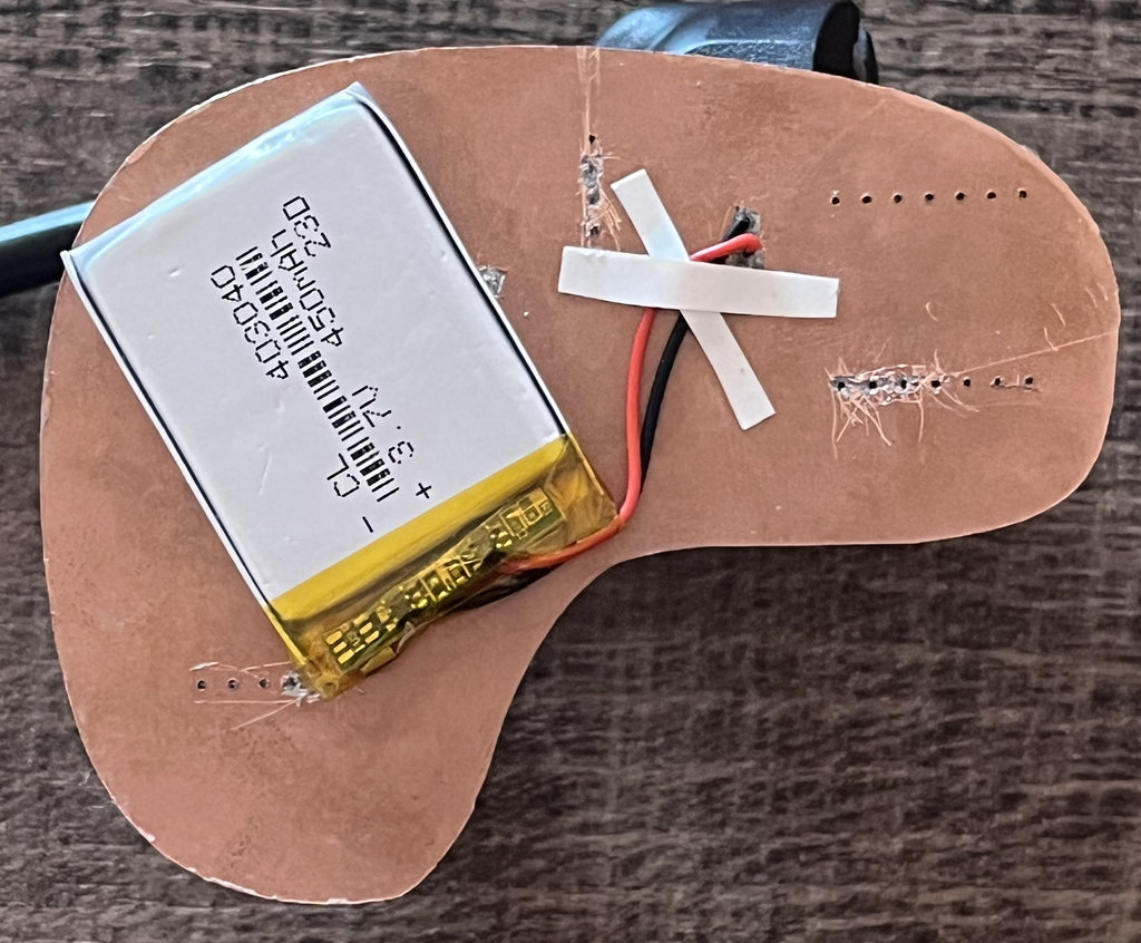
After confirming everything worked, I safely soldered the battery onto the PCB, along with the remaining components.
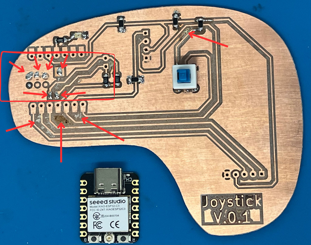
Since my PCB had copper layers on both sides, I cleaned the backside around critical pins to prevent short circuits. I also fixed the battery onto the PCB using double-sided tape to prevent it from moving.
Now it’s time to start programming and enjoy this process as much as possible 😄
During programming, I discovered some PCB design mistakes, which again were related to not reading the documentation carefully.
In this image, it is clearly shown that there is a line over A3, and it is also written 😩:
However, I had used this exact pin to read the battery voltage, which is why I couldn’t get correct readings.
To fix this, I swapped the joystick and battery pins on the ESP32-C3.
Using the Seeed Studio XIAO ESP32C3 documentation and asking the AI to:
"Write Arduino code for ESP32-C3 that reads a joystick, displays an animation on an SSD1306 OLED, shows X/Y values and battery voltage, and enters deep sleep when a button is pressed."
I got the following code. Below, I will explain what the code includes and what functions it contains.
Here is the complete code. Below, I will explain what the program does and describe the main functions included in it.
#include <Wire.h>
#include <Adafruit_GFX.h>
#include <Adafruit_SSD1306.h>
#define SCREEN_WIDTH 128
#define SCREEN_HEIGHT 32
#define OLED_RESET -1
#define SCREEN_ADDRESS 0x3C
// Pins
const int pinVRX = 2;
const int pinVRY = 3;
const int pinBat = 4;
const int pinBtn = 21;
const int pinLED = 10;
Adafruit_SSD1306 display(SCREEN_WIDTH, SCREEN_HEIGHT, &Wire, OLED_RESET);
void startAnimation() {
display.clearDisplay();
display.setTextSize(1);
display.setTextColor(SSD1306_WHITE);
for (int i = -50; i <= 30; i += 5) {
display.clearDisplay();
display.setCursor(i, 5);
display.print("SYSTEM BOOTING...");
display.display();
delay(10);
}
for (int w = 0; w <= 100; w += 4) {
display.drawRect(14, 20, 102, 8, SSD1306_WHITE);
display.fillRect(15, 21, w, 6, SSD1306_WHITE);
display.display();
delay(20);
}
delay(500);
}
void setup() {
pinMode(pinBtn, INPUT_PULLUP);
pinMode(pinLED, OUTPUT);
digitalWrite(pinLED, HIGH);
Wire.begin(7, 6);
if(!display.begin(SSD1306_SWITCHCAPVCC, SCREEN_ADDRESS)) for(;;);
startAnimation();
// Important for Battery Sensing: Set 12-bit resolution
analogReadResolution(12);
}
void cryingShutdown() {
display.clearDisplay();
display.setTextSize(1);
display.setTextColor(SSD1306_WHITE);
for (int tearY = 12; tearY < 32; tearY += 2) {
display.clearDisplay();
display.setCursor(40, 0);
display.print("POWERING OFF");
display.drawCircle(50, 12, 2, SSD1306_WHITE);
display.drawCircle(78, 12, 2, SSD1306_WHITE);
display.drawCircle(64, 28, 4, SSD1306_WHITE);
display.fillRect(60, 28, 8, 5, SSD1306_BLACK);
display.fillCircle(50, tearY, 2, SSD1306_WHITE);
display.fillCircle(78, tearY, 2, SSD1306_WHITE);
display.display();
delay(50);
}
delay(500);
}
void loop() {
if (digitalRead(pinBtn) == LOW) {
cryingShutdown();
display.ssd1306_command(SSD1306_DISPLAYOFF);
digitalWrite(pinLED, LOW);
// Use GPIO_LOW because you have a pull-up resistor
esp_deep_sleep_enable_gpio_wakeup(1ULL << pinBtn, ESP_GPIO_WAKEUP_GPIO_HIGH);
delay(100); // Small delay to ensure the pin is stable
esp_deep_sleep_start();
}
// --- SENSOR DATA READS ---
int xRaw = analogRead(pinVRX);
int yRaw = analogRead(pinVRY);
// Measure Battery (Input Device Assignment)
// Use analogReadMilliVolts for factory-calibrated accuracy
float readingMV = analogReadMilliVolts(pinBat);
// Multiply by 2 because the 100k/100k divider cuts voltage in half
float batV = (readingMV / 1000.0) * 2.0;
// --- LOGIC ---
String xDir = "0";
String yDir = "0";
if (xRaw < 1500) yDir = "DOWN"; else if (xRaw > 3000) yDir = "TOP";
if (yRaw < 1500) xDir = "LEFT"; else if (yRaw > 3000) xDir = "RIGHT";
display.clearDisplay();
// --- DRAW VISUAL INTERFACE ---
display.drawRect(95, 0, 32, 32, SSD1306_WHITE);
int dotX = map(yRaw, 0, 4095, 95 + 6, 127 - 6);
int dotY = map(xRaw, 0, 4095, 32 - 6, 0 + 6);
display.drawCircle(dotX, dotY, 6, SSD1306_WHITE);
display.fillCircle(dotX - 2, dotY - 2, 1, SSD1306_WHITE);
display.fillCircle(dotX + 2, dotY - 2, 1, SSD1306_WHITE);
display.drawLine(dotX - 2, dotY + 2, dotX + 2, dotY + 2, SSD1306_WHITE);
// --- DISPLAY TEXT ---
display.setTextSize(1);
display.setCursor(0, 0);
display.print("X: "); display.print(xDir);
display.setCursor(50, 0);
display.print("Y: "); display.print(yDir);
display.setCursor(0, 15);
display.print("Bat: ");
display.print(batV); display.print("V");
// --- ALERT SYSTEM ---
display.setCursor(0, 25);
if(batV < 3.4 && batV > 1.0) {
digitalWrite(pinLED, LOW);
display.print("!!! LOW BAT !!!");
} else {
digitalWrite(pinLED, HIGH);
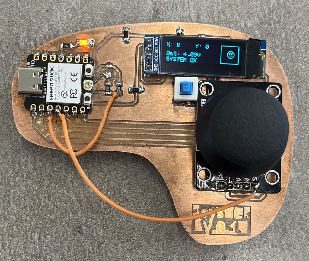
display.print("SYSTEM OK");
}
display.display();
delay(20);
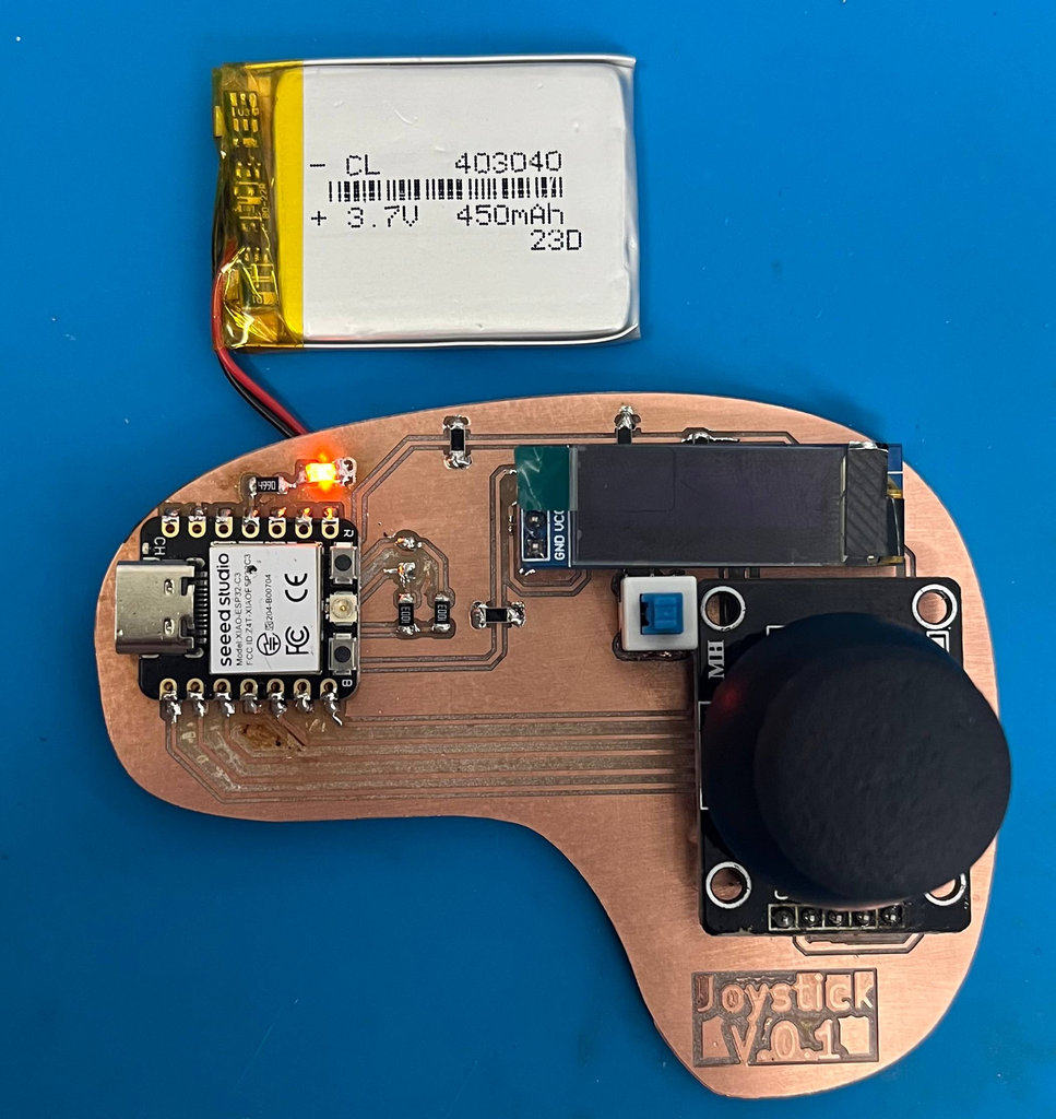
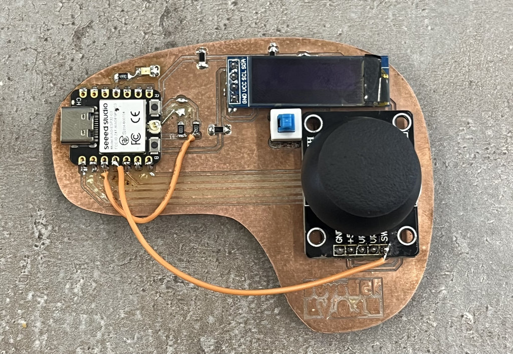
}Here is the joystick.
And here is a short video demonstrating how it works.
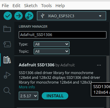
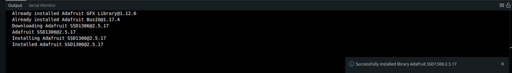
1. OLED library installation
Sketch ⟶ Include Library ⟶ Manage Libraries ⟶ Adafruit SSD1306 ⟶ Install
2. Interfacing Analog Inputs (The Core Goal)
The main purpose of my code is to read input from a joystick, which is a dual-potentiometer device. I use analogRead() and analogReadMilliVolts() to convert changing voltage levels from the joystick and battery into digital values.
Instead of just displaying raw numbers, I applied threshold logic (e.g., < 1500 or > 3000) to translate these signals into human-readable directions like: TOP, DOWN, LEFT, RIGHT
3. Battery Management & Calibration
Understanding electronics is an important part of my FabAcademy work. My code considers a 100k/100k resistor divider on the battery pin.
Since the voltage is halved by hardware, I multiply the reading by 2 to get the real value. I also use analogReadResolution(12) to take advantage of the full 12-bit resolution (0–4095) of the ESP32-C3 for better accuracy.
-
Battery Voltage Divider Explained:
- The ESP32-C3 ADC cannot directly measure the full voltage of a Li-ion battery, which ranges from roughly 3.0V (empty) to 4.2V (fully charged). Most ESP32 pins are only safe up to 3.3V, and the internal ADC has a specific measurable range based on its attenuation setting.
The Formula:
My
100k/100kdivider is a "half-voltage" circuit. The output voltage (Vout) sent to the ESP32 pin is calculated as:Vout = Vin × (R2 / (R1 + R2))With
R1=100kandR2=100k:Vout = Vbatt × (100,000 / (100,000 + 100,000)) = Vbatt * 0.5
4. Visual Feedback (I2C Communication)
I implemented an OLED display using the I2C protocol (Wire.h). This allows real-time visualization of the input data.
Using the map() function, I convert joystick values (0–4095) into screen coordinates (128×32), creating a “moving eye” effect that follows joystick movement.
5. Power Management (Advanced Feature)
To demonstrate deeper understanding, I added a Deep Sleep mode.
I created a cryingShutdown() function to add a small UX element before the system turns off. Using esp_deep_sleep_start(), the device enters a low-power state, and it wakes up only when the button is pressed.
6. The “Alert System”
I implemented a feedback safety system.
When the battery voltage drops below 3.4V, the system triggers:
- A visual alert on the display:
!!! LOW BAT !!! - A physical alert by
turningonan LED
Quick Joystick Direction Test
Before moving on, I wanted a simple way to just see the joystick's movement direction, without all the ESP-NOW and OLED logic running at the same time. So I asked Claude to generate a small test sketch that only reads the joystick and prints the direction to the Serial Monitor.
AI prompt:
"Simplify my joystick code to just read the X/Y analog values and the button, and print the current movement direction (UP, DOWN, LEFT, RIGHT, diagonals, or CENTER) to the Serial Monitor, using the same JOY_CENTER and JOY_DEADZONE calibration values I already have."
I tested it directly on my final joystick version, and it was a nice, fast way to confirm the calibration and deadzone values were still correct before trusting the joystick inside the full game logic.
This week was both challenging and really satisfying at the same time. I worked on designing and building a joystick-based PCB for my car-robot, and honestly, it was not an easy process. I made several mistakes, especially because I didn’t always read the documentation carefully (again 😅), but each mistake helped me understand the system much better.
I really enjoyed the moment when everything finally started working — especially seeing the OLED respond to the joystick and the whole system come alive. That feeling is always worth all the struggles before it.
At the same time, I think this week taught me an important lesson: hardware is not forgiving. Even a small mistake in pins, footprint, or connections can cost a lot of time. But maybe that’s also what makes it interesting?
I also realized that I’m starting to feel more confident combining different systems together — PCB design, programming, and electronics — and making them actually work as one system.
Individual assignment
AI prompt:
“And Generate image when she fineshed Week 9”