Week 9. Input devices
Group assignment
During this week’s group assignment, we used an oscilloscope to measure the analog levels and digital signals of the input devices connected to our PCB.
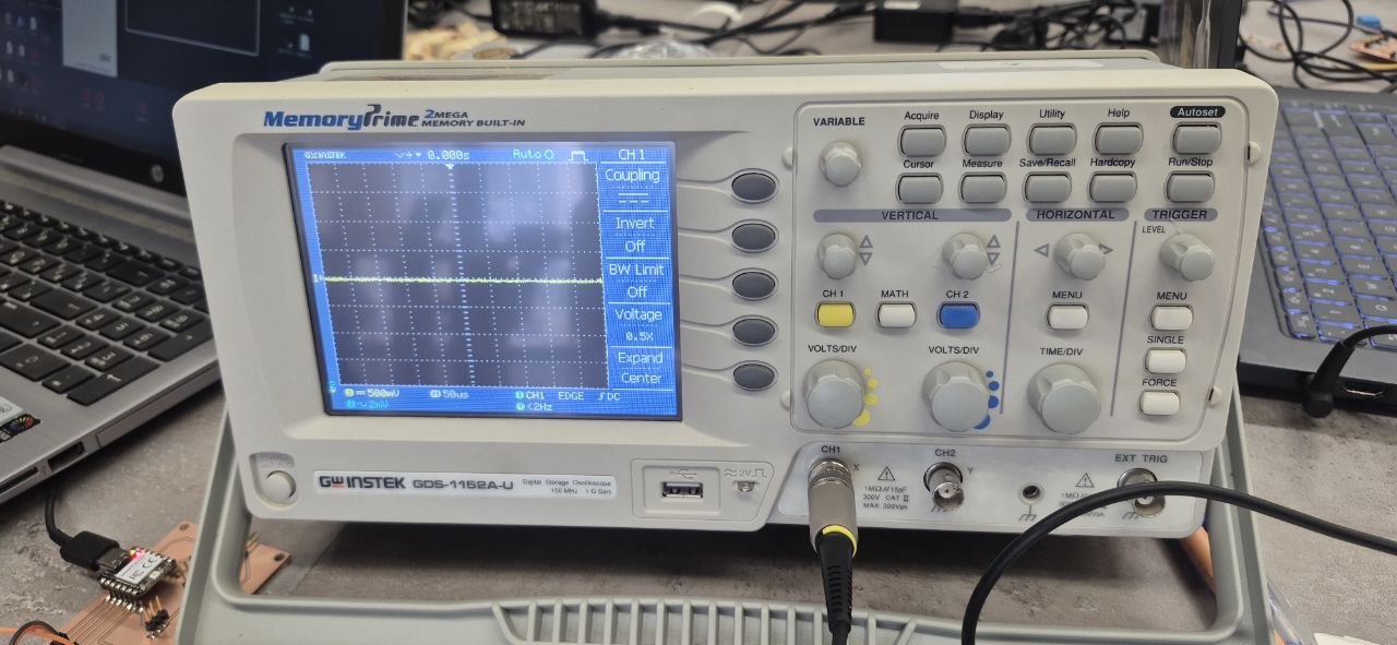
In the first experiment, we applied voltage (V) to the analog pin of a variable resistor sensor. By rotating it, we observed that the waveform on the screen increased and decreased proportionally to the rotation. In the case of an analog signal, the variations change smoothly.
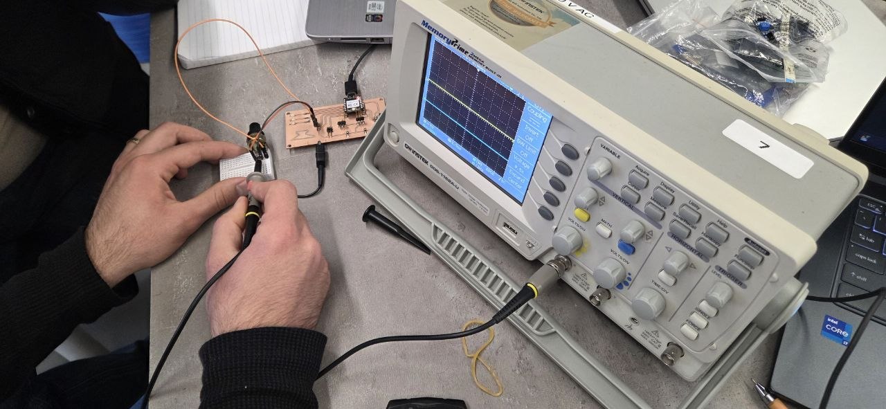
In the second experiment, we applied voltage to the digital pin of a photoresistor. When we turned the light on and off over it, we observed sharp changes on the oscilloscope screen.
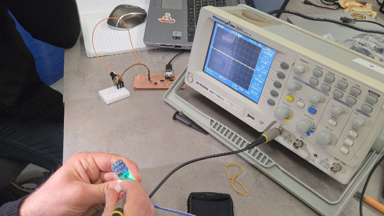
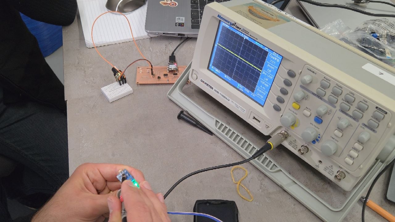
Then, by applying voltage to the analog pin and repeating the same light on/off process, we observed smooth variations on the oscilloscope, similar to the analog case.
Individual Assignment
This week I explored the operation of a thermistor and its application as an input device in electronic systems. A thermistor is a temperature-sensitive resistor whose resistance changes as the temperature varies. It is widely used in temperature measurement, monitoring, and protection systems.
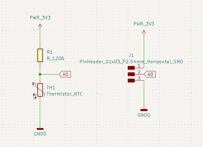
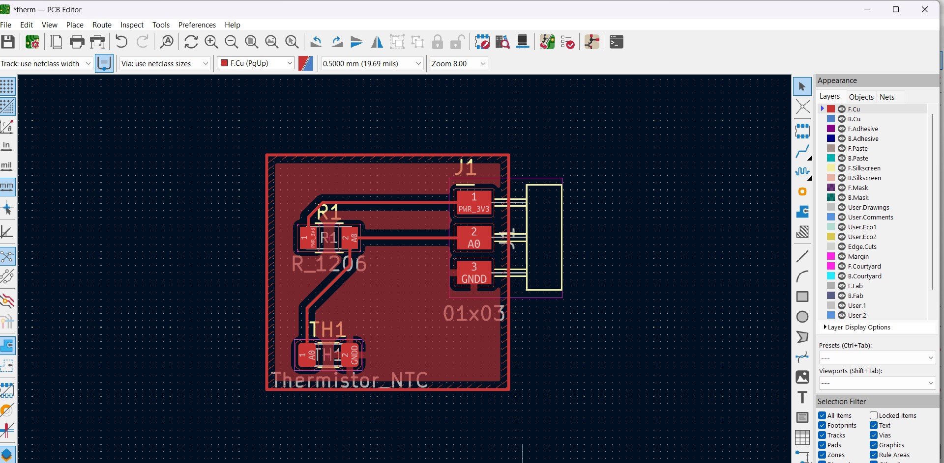
The first stage of the assignment was to design a PCB for the thermistor sensor using KiCad. I began by creating the schematic, which included the thermistor, a series resistor, and a connector for interfacing with the microcontroller. After completing the schematic, I designed the PCB layout by placing the components and routing the traces. During this process, I paid attention to component placement and trace organization to ensure a simple and reliable design.
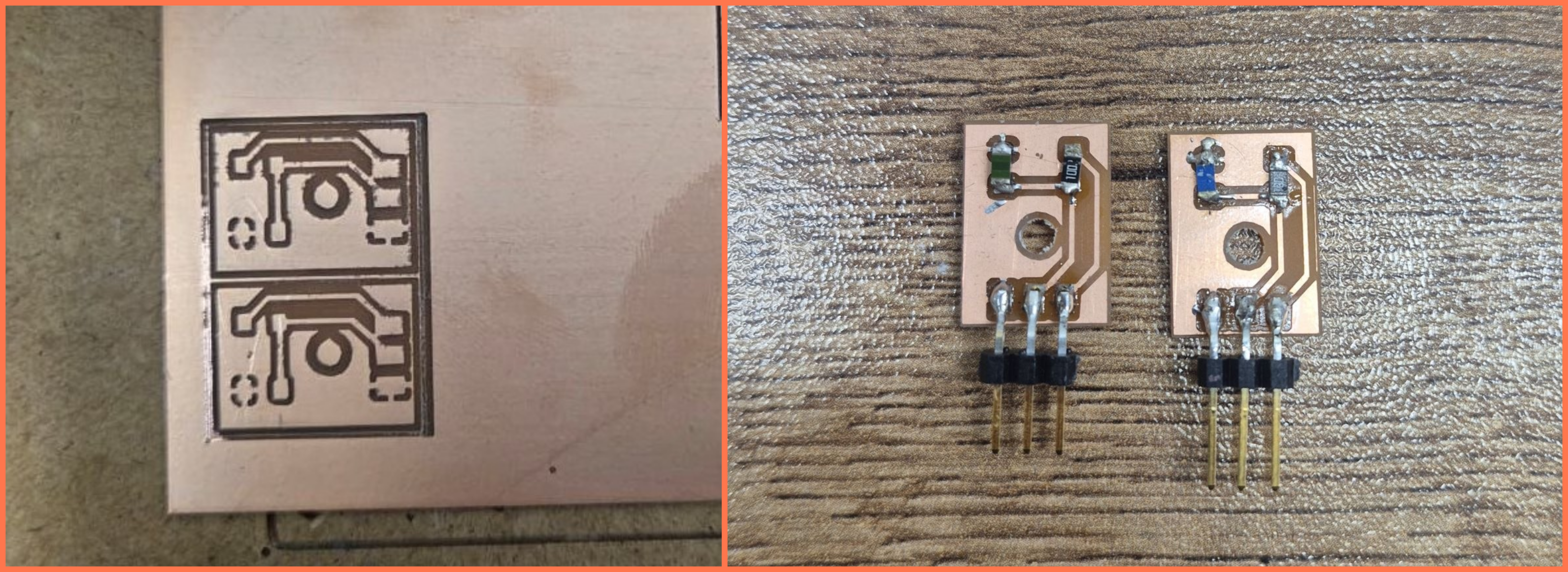
As part of this assignment, I designed and fabricated two different thermistor sensor boards. The first board was designed for a 10kΩ NTC thermistor with a 1kΩ series resistor, while the second board was designed for a 100kΩ NTC thermistor with a 10kΩ series resistor. Both boards followed the same design principles but were optimized for their respective thermistors.
After fabricating the PCBs, I assembled the boards and connected them to a XIAO RP2040 microcontroller.
The thermistor and the series resistor formed a voltage divider circuit, allowing temperature-dependent voltage changes to be measured by the analog input of the microcontroller.
Once the hardware was assembled, I developed Arduino programs for each sensor configuration. The programs continuously read the analog voltage, calculated the thermistor resistance, and converted the resistance value into temperature using the Beta coefficient equation. The calculated values were displayed through the Serial Monitor.
Testing and Results
To evaluate the performance of the sensors, I tested both thermistor boards separately and compared their responses to temperature changes.
Experiment 1 – 10kΩ Thermistor
For the first experiment, I tested a 10kΩ NTC thermistor connected in a voltage divider circuit with a 1kΩ fixed resistor. The objective of this experiment was to measure temperature by reading the analog voltage generated by the voltage divider and converting it into a temperature value.
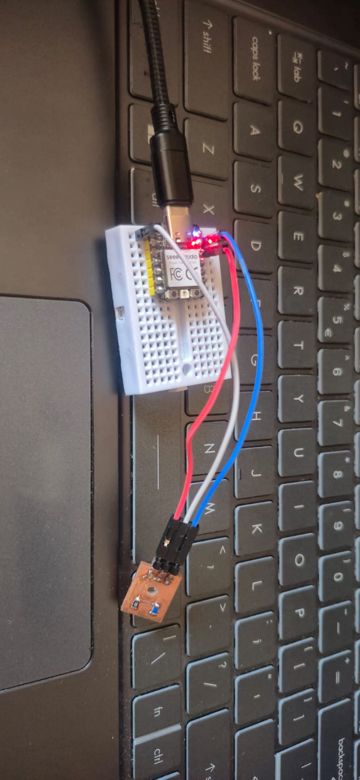
The thermistor board was connected to the Seeed Studio XIAO RP2040, with the output of the voltage divider connected to the A0 analog input pin. The microcontroller continuously sampled the analog signal using its 12-bit ADC, producing values in the range of 0 to 4095.
The Arduino program first reads the analog value from the thermistor. Using the measured ADC value and the known value of the series resistor, it calculates the thermistor resistance based on the voltage divider equation. The calculated resistance is then converted into temperature using the Beta coefficient equation, which requires the thermistor’s nominal resistance (10kΩ at 25°C), the nominal temperature, and the Beta coefficient (3950).
Every second, the program displays the following values in the Serial Monitor:
- ADC – the raw analog reading from the microcontroller.
- Resistance – the calculated thermistor resistance in ohms.
- Temperature – the calculated temperature in degrees Celsius.
To verify the operation of the sensor, I observed the values in the Serial Monitor while changing the thermistor temperature by touching it with my finger and by applying warm air. As expected for an NTC (Negative Temperature Coefficient) thermistor, its resistance decreased as the temperature increased, while the calculated temperature increased accordingly. This confirmed that both the hardware and the software were functioning correctly.
Through this experiment, I gained practical experience in reading analog sensor data, calculating resistance using a voltage divider, and converting resistance into temperature using the Beta coefficient equation. The results demonstrated that the custom-designed PCB and the Arduino program provided stable and reliable temperature measurements.
#include <math.h>

// Thermistor analog input pin
#define THERM_PIN A0

// Fixed resistor value (1kΩ)
#define SERIES_RESISTOR 1000.0

// Thermistor nominal resistance at 25°C (10kΩ)
#define NOMINAL_RESISTANCE 10000.0

// Nominal temperature (°C)
#define NOMINAL_TEMPERATURE 25.0

// Thermistor Beta coefficient
#define B_COEFFICIENT 3950.0

void setup() {
  // Initialize serial communication
  Serial.begin(115200);
}

void loop() {

  // Read analog value from the thermistor
  int adc = analogRead(THERM_PIN);

  // Check for invalid sensor reading
  if (adc == 0) {
    Serial.println("Sensor error");
    delay(1000);
    return;
  }

  // Calculate thermistor resistance
  float resistance = SERIES_RESISTOR * (4095.0 / (float)adc - 1.0);

  float temp;

  // Calculate temperature using the Beta equation
  temp = resistance / NOMINAL_RESISTANCE;
  temp = log(temp);
  temp /= B_COEFFICIENT;
  temp += 1.0 / (NOMINAL_TEMPERATURE + 273.15);
  temp = 1.0 / temp;
  temp -= 273.15;

  // Display ADC value
  Serial.print("ADC: ");
  Serial.print(adc);

  // Display calculated resistance
  Serial.print("  Resistance: ");
  Serial.print(resistance);
  Serial.print(" ohm");

  // Display temperature in Celsius
  Serial.print("  Temp: ");
  Serial.print(temp);
  Serial.println(" C");

  // Wait 1 second before the next measurement
  delay(1000);
}
AI Prompt
Help me write Arduino code for the XIAO RP2040 to read a 10kΩ NTC thermistor connected in a voltage divider circuit, calculate the temperature in degrees Celsius using the Beta equation, and print the ADC value, resistance, and temperature to the Serial Monitor.
Experiment 2 – 100kΩ Thermistor
In the second experiment, I replaced the sensor with a 100kΩ NTC thermistor and used a 10kΩ series resistor to form the voltage divider circuit. The hardware setup remained the same, while the thermistor parameters in the Arduino program were updated to match the characteristics of the new sensor.
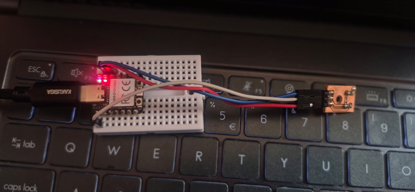
The thermistor board was connected to the Seeed Studio XIAO RP2040, with the voltage divider output connected to the A0 analog input. The microcontroller continuously measured the analog voltage using its 12-bit ADC and converted the readings into digital values ranging from 0 to 4095.
The Arduino program calculated the thermistor resistance from the measured ADC value using the voltage divider equation. The resistance value was then converted into temperature using the Beta coefficient equation, with the nominal resistance changed to 100kΩ at 25°C, while the nominal temperature (25°C) and the Beta coefficient (3950) remained unchanged.
Every second, the program displayed the following values in the Serial Monitor:
- ADC – the raw analog reading from the microcontroller.
- Resistance – the calculated thermistor resistance in ohms.
- Temperature – the calculated temperature in degrees Celsius.
To evaluate the sensor performance, I monitored the Serial Monitor while heating the thermistor with warm air. During the experiment, the thermistor responded to temperature changes by changing its resistance, and the calculated temperature values updated continuously. This confirmed that the sensor was able to detect temperature variations and provide stable measurements.
Comparing the two experiments showed that although both thermistors operated using the same principle, the 100kΩ thermistor produced a different ADC response and resistance range than the 10kΩ thermistor. This demonstrated how the nominal resistance of the thermistor influences the voltage divider output and the measurement characteristics of the sensor.
Through this experiment, I gained a better understanding of thermistor behavior, analog data acquisition, and temperature calculation using the Beta equation. The results confirmed that the designed PCB and the Arduino program successfully measured temperature and can be used in various temperature monitoring applications.
#include <math.h>

// Thermistor analog input pin
#define THERM_PIN A0

// Fixed resistor value (10kΩ)
#define SERIES_RESISTOR 10000.0

// Thermistor nominal resistance at 25°C (100kΩ)
#define NOMINAL_RESISTANCE 100000.0

// Nominal temperature for the thermistor (°C)
#define NOMINAL_TEMPERATURE 25.0

// Thermistor Beta coefficient
#define B_COEFFICIENT 3950.0

void setup() {
  // Start serial communication
  Serial.begin(115200);
}

void loop() {

  // Read analog value from thermistor
  int adc = analogRead(THERM_PIN);

  // Check for invalid reading
  if (adc == 0) {
    Serial.println("Sensor error");
    delay(1000);
    return;
  }

  // Calculate thermistor resistance using voltage divider formula
  float resistance = SERIES_RESISTOR * (4095.0 / (float)adc - 1.0);

  float temp;

  // Apply Beta equation to calculate temperature
  temp = resistance / NOMINAL_RESISTANCE;
  temp = log(temp);
  temp /= B_COEFFICIENT;
  temp += 1.0 / (NOMINAL_TEMPERATURE + 273.15);
  temp = 1.0 / temp;
  temp -= 273.15;

  // Reverse displayed temperature
  // (Used because the sensor is mounted in reverse orientation)
  temp = 50.0 - temp;

  // Print ADC value
  Serial.print("ADC: ");
  Serial.print(adc);

  // Print calculated resistance
  Serial.print("  Resistance: ");
  Serial.print(resistance);
  Serial.print(" ohm");

  // Print calculated temperature
  Serial.print("  Temp: ");
  Serial.print(temp);
  Serial.println(" C");

  // Wait 1 second before next reading
  delay(1000);
}
AI Prompt
Help me write Arduino code for the XIAO RP2040 to read a 100kΩ NTC thermistor connected in a voltage divider circuit, calculate the temperature in degrees Celsius using the Beta equation, and print the ADC value, resistance, and temperature to the Serial Monitor.
Comparison and Analysis
By testing both thermistor boards, I was able to compare the behavior of two NTC thermistors with different nominal resistance values. In the first experiment, I used a 10kΩ NTC thermistor with a 1kΩ series resistor, while in the second experiment, I used a 100kΩ NTC thermistor with a 10kΩ series resistor.
Both sensors successfully detected temperature changes and transmitted the measured values to the XIAO RP2040 through the analog input. The Arduino program calculated the thermistor resistance from the ADC reading and converted it into temperature using the Beta coefficient equation.
Although both thermistors operated according to the same principle, they produced different ADC readings and resistance values because of their different nominal resistances and the different series resistors used in the voltage divider. The 10kΩ thermistor responded within a lower resistance range, while the 100kΩ thermistor operated within a much higher resistance range. Despite these differences, both sensor boards provided stable temperature measurements and correctly responded to heating.
This assignment helped me understand how the nominal resistance of a thermistor influences the behavior of a voltage divider and how the selection of the series resistor affects the analog measurements. I also gained practical experience in PCB design, PCB fabrication, soldering SMD components, integrating analog sensors with the XIAO RP2040, and developing Arduino programs for temperature measurement.
Overall, both experiments demonstrated that NTC thermistors are reliable analog input devices and can be successfully used for temperature monitoring and control applications.
PCB Redesign
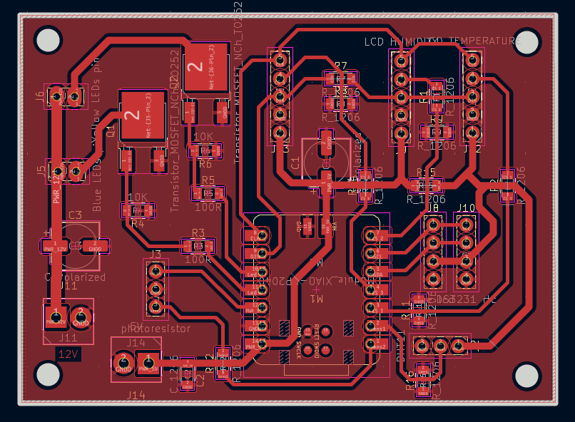
During this week, I also completed the design of my final project PCB. In the initial stages of the project, I had not yet made a final decision about the type of display I would use. Therefore, the original PCB design included SDA and SCL connections for displays that communicate through the I2C interface. The initial board design can be found in Week 6.
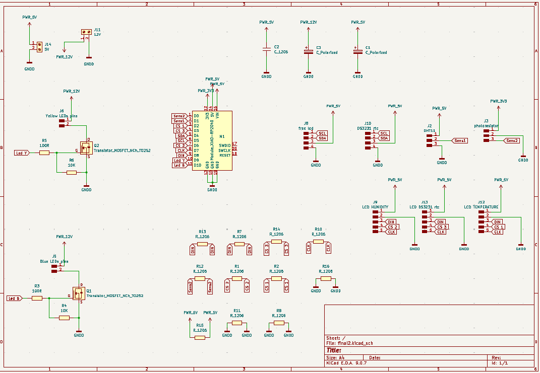
Later, I researched different display options and their communication methods. After comparing several alternatives, I chose a MAX7219-based LED matrix display because it is well suited for my project and provides simple control through the microcontroller.
The MAX7219 module uses the following pins:
- VCC – Power supply
- GND – Ground
- DIN – Data Input
- CLK – Clock signal
- CS – Chip Select
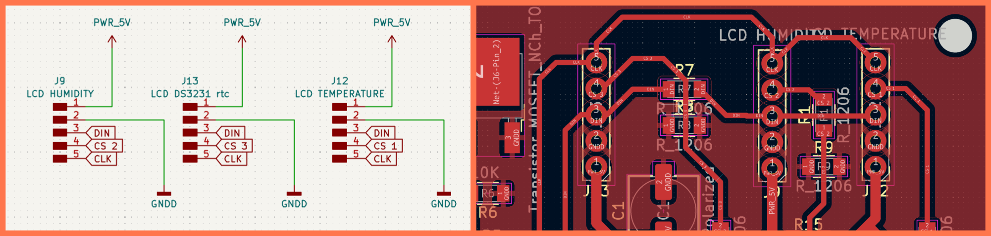
As a result, I modified the PCB design by replacing the I2C connections (SDA and SCL) with DIN, CLK, and CS connections required by the MAX7219 display. This change allows the display to be connected correctly and enables the microcontroller to communicate with it efficiently.
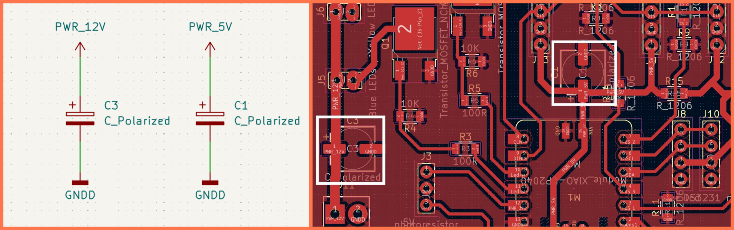
In addition, I added capacitors to the PCB design to improve power supply stability and reduce electrical noise and interference. These capacitors were placed on the power lines to ensure more reliable and stable operation of both the MAX7219 module and the microcontroller.
After implementing these modifications, the PCB was fully adapted for the MAX7219 display, providing the necessary connections and stable power distribution.
Voltage Regulator
During the PCB design process, I also modified the power input section. Instead of using a standard DC power jack, I added two 2-pin screw terminals. The first terminal is used to receive the 12V input supply, while the second is used to deliver the regulated 5V supply to the PCB. This solution makes the power connections simpler, more reliable, and easier to integrate into the final system.
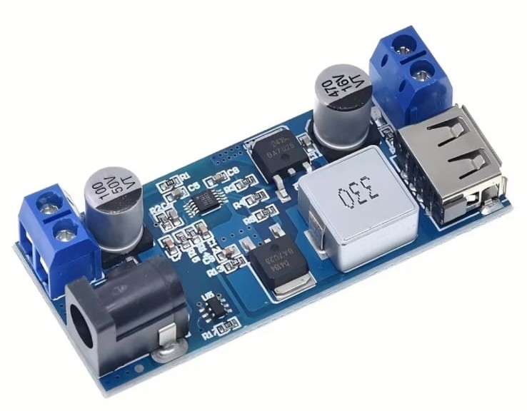
To provide a stable power supply, I used an LM2596 (XY-3606) DC-DC Buck Voltage Regulator module. Its purpose is to convert the 12V input voltage into a stable 5V output voltage, which is used to power my custom PCB and the XIAO RP2040 microcontroller.
The LM2596 is a step-down (buck) switching voltage regulator that efficiently converts a higher input voltage into a lower output voltage. As a switching regulator, it offers higher efficiency, lower power loss, and generates less heat than linear voltage regulators.
Main specifications (Datasheet):
- Module: LM2596 DC-DC Buck Converter (XY-3606)
- Input Voltage: 4.5V – 40V DC
- Output Voltage: 1.25V – 35V DC (adjustable)
- Maximum Output Current: up to 3A
- Conversion Efficiency: up to 92%
- Switching Frequency: 150 kHz
- Protection: Overcurrent and thermal protection
For my project, I adjusted the regulator output to 5V to safely power the XIAO RP2040 and the other electronic components.
Input Sensors Research and Implementation
Before finalizing the PCB design, I studied the input sensors used in the project to ensure proper integration and compatibility with the microcontroller.
DHT11 Sensor
Before using the DHT11 sensor, I studied its datasheet and technical documentation to better understand its working principle, pinout, electrical characteristics, and connection requirements. This helped me clearly understand how the sensor operates and ensured its correct integration into my project.
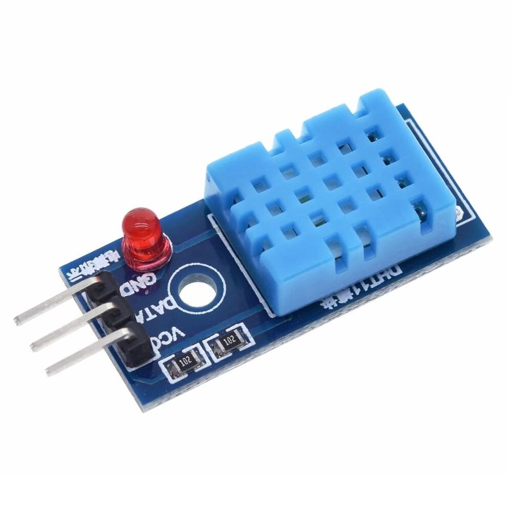
The DHT11 is a digital sensor designed for measuring ambient temperature and relative humidity. It includes a humidity sensing element, a temperature sensor, and an internal microcontroller that processes the data and transmits it through a single digital (DATA) pin.
The DHT11 operates with a 3.3–5V power supply and has the following main pins:
- VCC – Power supply
- DATA – Data output
- GND – Ground
DS3231 RTC Module
Before using the DS3231 module, I studied its datasheet and technical documentation to better understand its working principle, I²C communication interface, pinout, and connection requirements. This helped me understand the module’s behavior and ensured its correct integration into my project.
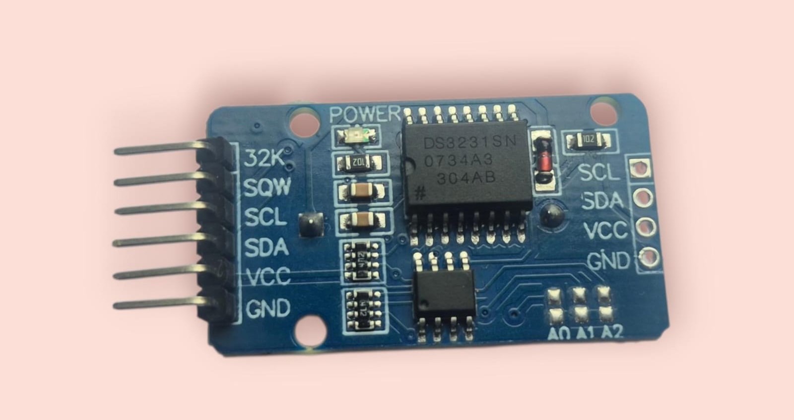
The DS3231 is a high-precision Real-Time Clock (RTC) module that keeps track of date and time even when the main power is disconnected, thanks to its backup battery. It uses a temperature-compensated crystal oscillator (TCXO), which provides high accuracy and minimal time drift.
The DS3231 communicates with the microcontroller via the I²C interface.
The DS3231 has the following main pins:
- VCC – Power supply
- GND – Ground
- SDA – Data line
- SCL – Clock line
After making these changes, the PCB design was fully finalized and prepared for the milling (fabrication) stage.
PCB Milling
After completing the final PCB design, I moved on to the manufacturing stage. First, I exported the required milling files from KiCad and used a CNC milling machine to fabricate the board. The milling process produced the PCB traces and the board outline, preparing it for assembly.
Once the milling process was completed, I removed the board from the work surface and carefully inspected all traces to ensure that there were no broken or damaged connections.
PCB Assembly and Soldering
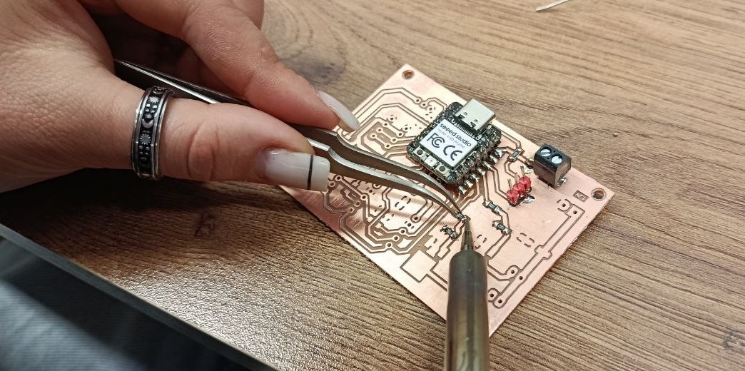
The next step was component placement and soldering. I started by soldering the small SMD components, including resistors, capacitors, and the microcontroller. After that, I soldered the programming header, power connections, and the connector intended for the MAX7219 display.
During the soldering process, I paid close attention to the quality of each connection to ensure reliable electrical contact and proper operation of the board.
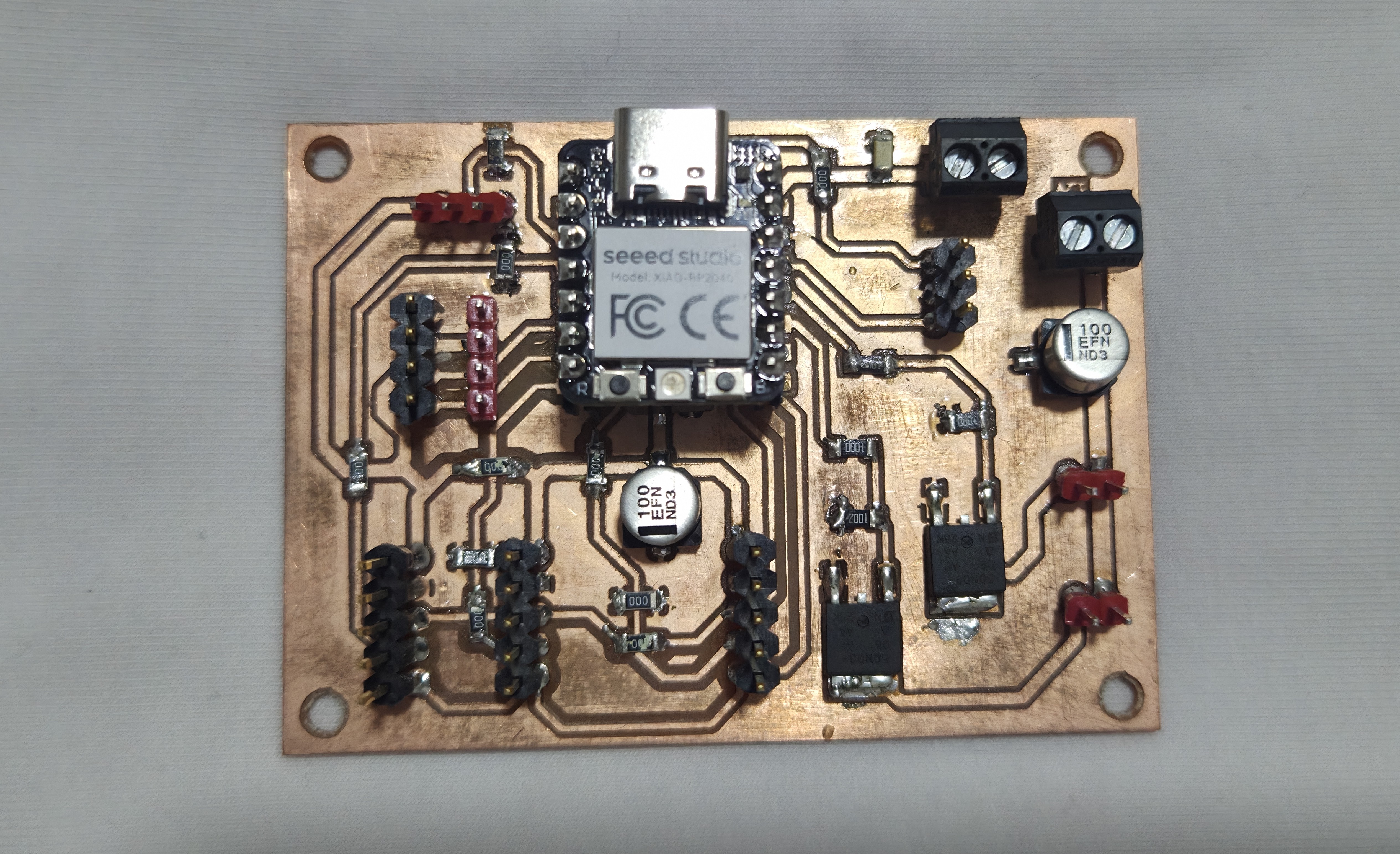
Final Board
As a result, I successfully assembled the final PCB for my project. The board includes the microcontroller, the required connections for the MAX7219 display, and the capacitors added for power stabilization.
The completed board is ready for programming, testing, and integration into the final project.
After completing the soldering process, I proceeded to test the functionality of the board to ensure that all components were properly connected and operating as expected. Since my final project PCB includes both the DHT11 and DS3231 modules, it was important to verify not only the electrical connections but also the stability of communication between these modules and the microcontroller.
As a first step, I carefully inspected all soldered connections to check for possible short circuits, weak joints, or incorrect connections that could affect the board’s performance. After confirming that the assembly was completed correctly, I connected the DHT11 and DS3231 modules to the board and then connected the board to the computer.
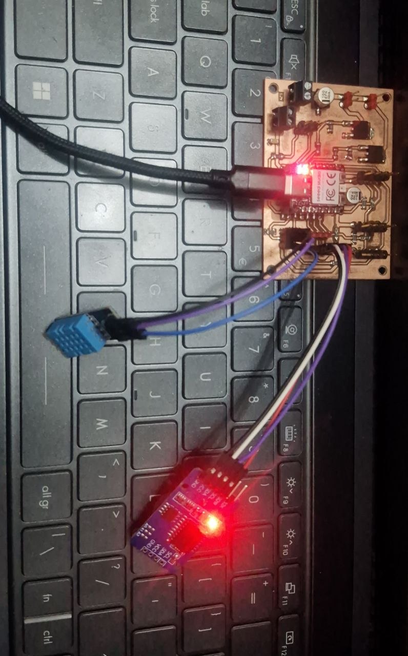
After that, I uploaded a test program designed to read data from both modules simultaneously.
#include "DHT.h"
#include "RTClib.h"

// -------------------- DHT11 Sensor Setup --------------------
#define DHTPIN 27        // Pin where DHT11 data line is connected
#define DHTTYPE DHT11    // Sensor type definition

DHT dht(DHTPIN, DHTTYPE);  // Create DHT sensor object

// -------------------- RTC Module Setup --------------------
RTC_DS3231 rtc;  // Create RTC (real-time clock) object

void setup() {
  Serial.begin(9600);  // Initialize serial communication for debugging

  // Initialize DHT11 sensor
  dht.begin();

  // Initialize RTC module
  if (!rtc.begin()) {
    Serial.println("Couldn't find RTC");  // Error message if RTC not detected
    while (1);  // Stop execution if RTC is not found
  }

  // Set RTC time to compile time (run once, then comment this line)
  rtc.adjust(DateTime(F(__DATE__), F(__TIME__)));

  Serial.println("System started");
}

void loop() {
  // -------------------- Read RTC Data --------------------
  DateTime now = rtc.now();  // Get current date and time

  // -------------------- Read DHT11 Data --------------------
  float temp = dht.readTemperature();  // Read temperature in Celsius
  float hum = dht.readHumidity();      // Read humidity percentage

  // -------------------- Print Date and Time --------------------
  Serial.print("Date: ");
  Serial.print(now.year());
  Serial.print("/");
  Serial.print(now.month());
  Serial.print("/");
  Serial.print(now.day());

  Serial.print("  Time: ");
  Serial.print(now.hour());
  Serial.print(":");
  Serial.print(now.minute());
  Serial.print(":");
  Serial.println(now.second());

  // -------------------- Print Sensor Data --------------------
  if (isnan(temp) || isnan(hum)) {
    Serial.println("Error reading DHT sensor");  // Handle sensor read error
  } else {
    Serial.print("Temp: ");
    Serial.print(temp);
    Serial.print(" °C   ");

    Serial.print("Humidity: ");
    Serial.print(hum);
    Serial.println(" %");
  }

  Serial.println("----------------------"); // Separator for readability

  delay(2000);  // Wait 2 seconds before next reading
}
AI Prompt
The DHT11, DS3231, and MAX7219 code was based on the tested and working code developed during previous weekly assignments. For this assignment, only the necessary modifications were made to integrate the modules into my final project and meet the communication requirements.
The program continuously collected temperature and humidity data from the DHT11 sensor while also retrieving real-time date and time information from the DS3231 RTC module. Using the Serial Monitor in Arduino IDE, I monitored the incoming values to verify whether the readings were stable and updated correctly over time.
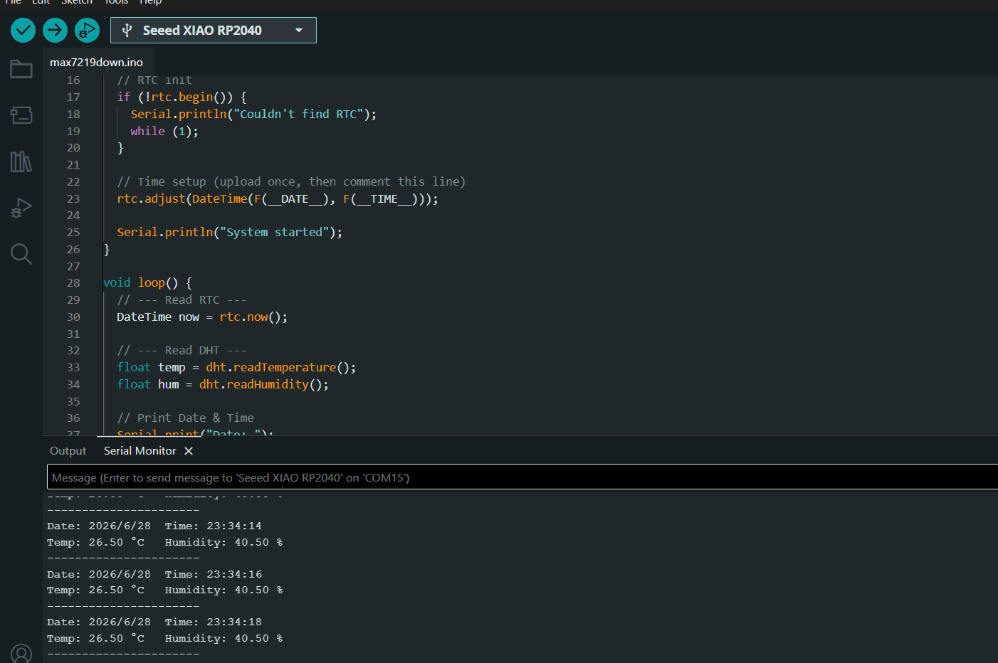
The test results confirmed that both modules were functioning properly. The DHT11 sensor successfully measured environmental temperature and humidity, while the DS3231 module accurately provided date and time information. This confirmed that the board was assembled correctly and that communication between all major components was stable and reliable.
Since this week’s assignment focused on input devices, this testing process was especially important because it demonstrated that my board could successfully receive, process, and display real-time data from external sensors. This also gave me confidence that the system was ready for further programming and integration into my final project.
Conclusion
This week’s assignment provided valuable experience in designing, fabricating, and testing analog input devices. I designed and manufactured two thermistor sensor PCBs, integrated them with the XIAO RP2040, and successfully measured temperature using analog input and the Beta coefficient equation.
In addition to the thermistor experiments, I completed and assembled the PCB for my final project, improved the hardware design by adapting it for the MAX7219 display, and verified the operation of the DHT11 and DS3231 input modules. Testing confirmed that all sensors communicated reliably with the microcontroller and produced stable, accurate readings.
Overall, this assignment strengthened my understanding of analog sensing, voltage divider circuits, PCB design and fabrication, sensor integration, and Arduino programming. The completed hardware and software provide a solid foundation for the next stages of my final project.