Week 2. Computer Aided design
Choosing Softwares
![]()
This image was created by downloading different logos and arranging them side by side in Adobe Photoshop to form a single composition.
This week, we are exploring new software and technologies that are directly related to the idea of my final project and can be useful during its development process. While studying the available software, I identified several tools that I have been working with for a long time AI Illustrator, Photoshop, FreeCad
Compressing Files
Image Compression
Fab Lab instructor Rudolf Igityan recommended using Image Compressorfor compressing images used in documentation.
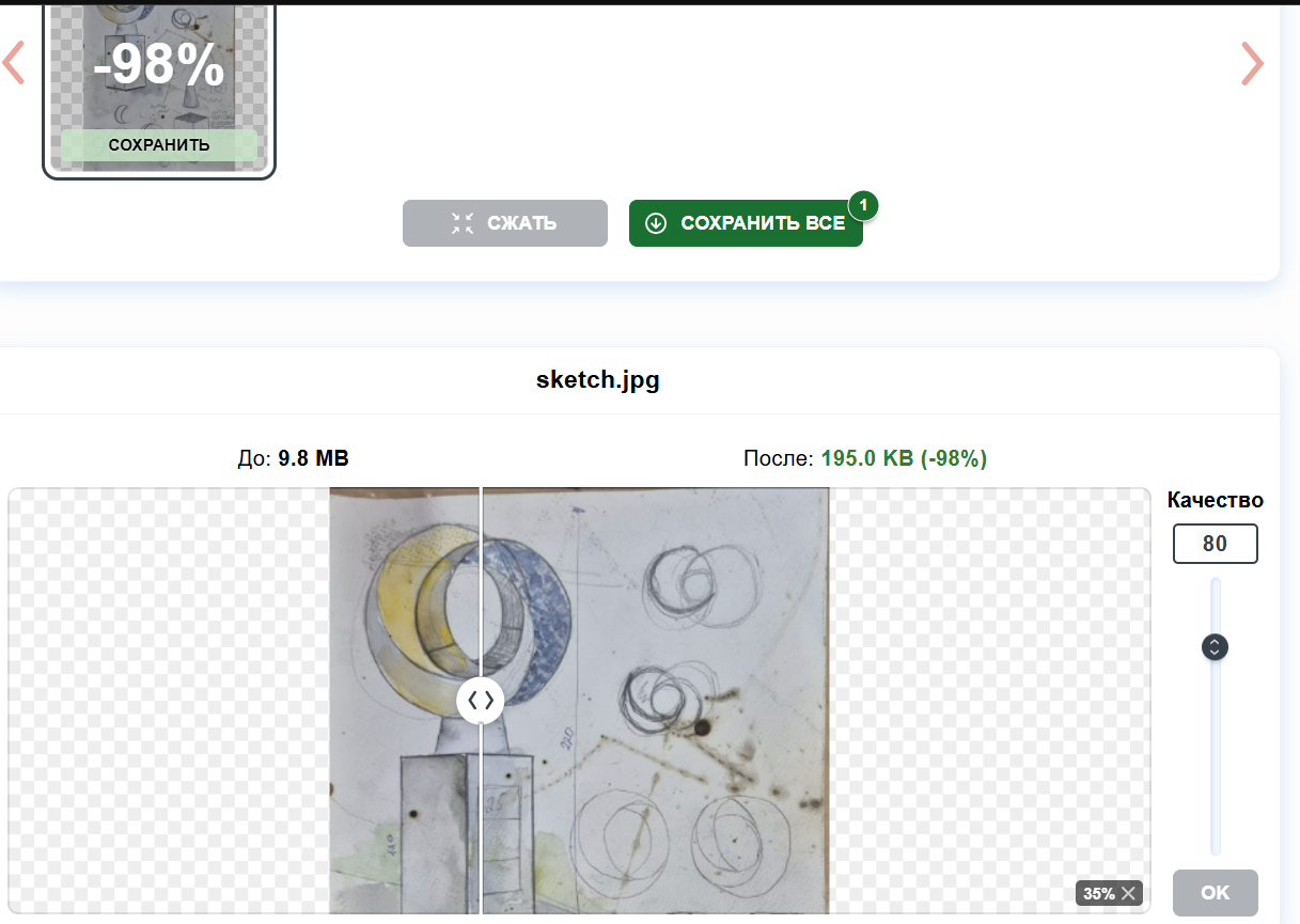
To test the compression process, I selected an image with an original size of 9.76 MB and compressed it using different quality settings.
First, I used a quality value of 80, which reduced the file size to 195.0 KB while maintaining good visual quality.
Then I lowered the quality to 10, reducing the file size even further to only 22.8 KB.
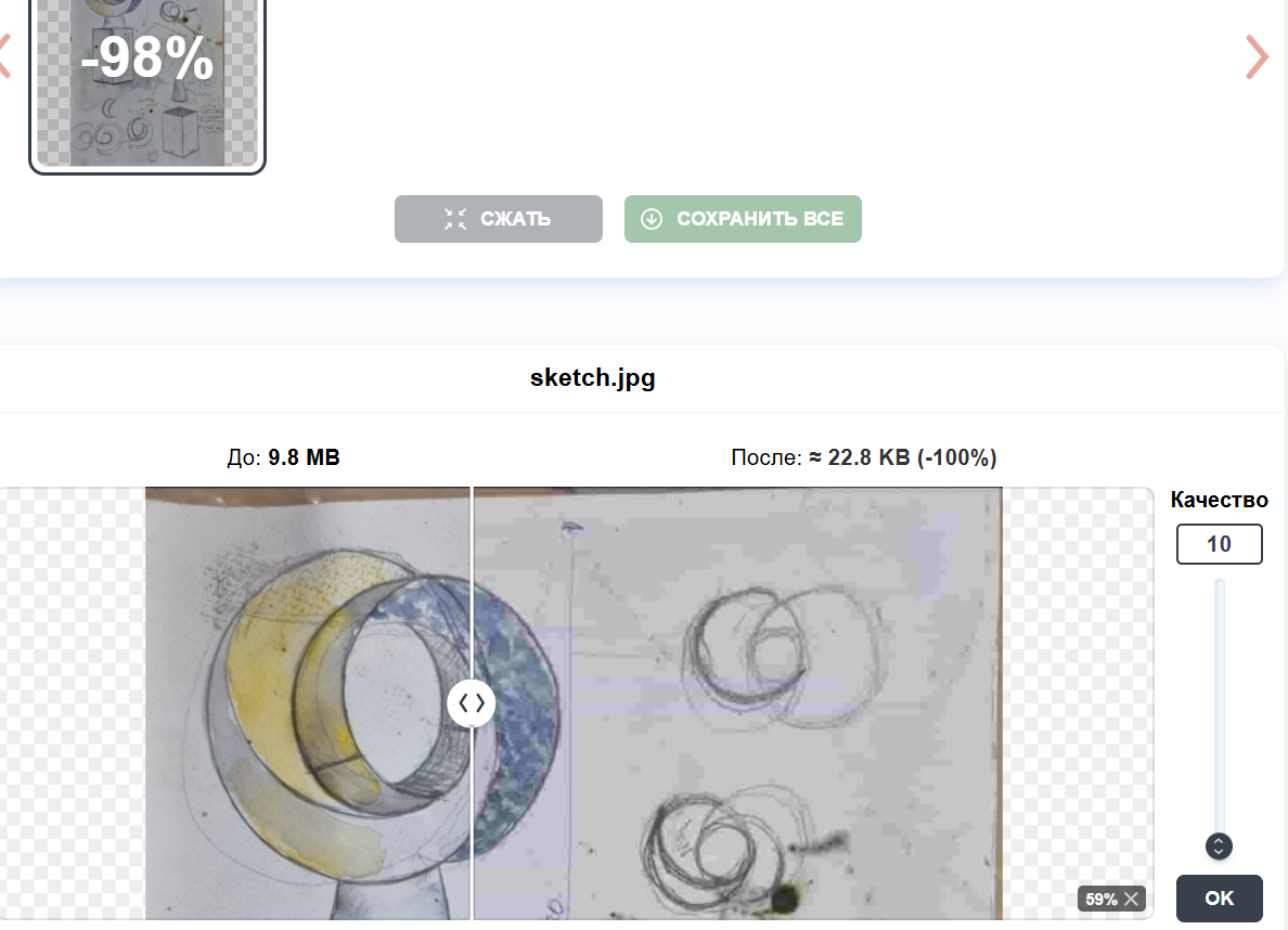
However, at quality 10 the image became noticeably distorted, and compression artifacts were clearly visible. Because of this, I increased the quality setting to 40, which provided a much better balance between file size and image quality.
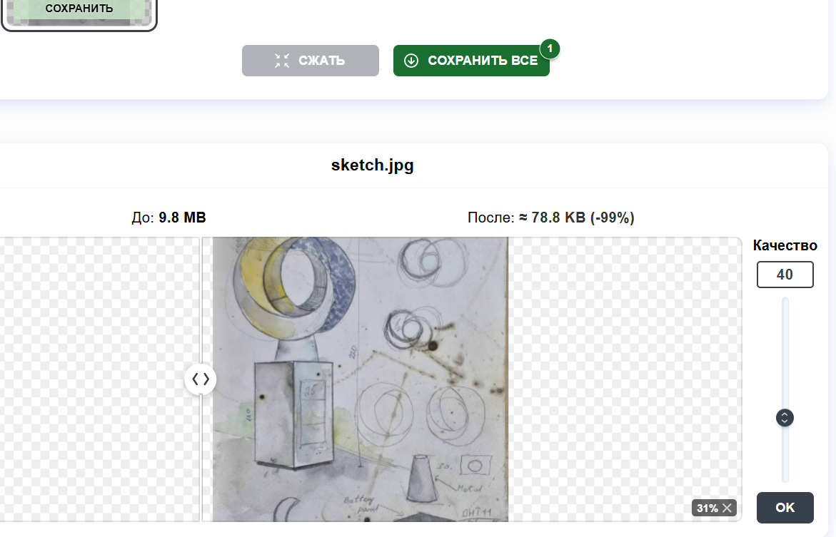
I believe that a quality value of 40 works well for my documentation images, as it significantly reduces file size while preserving enough detail and clarity for viewing.
Video Compression
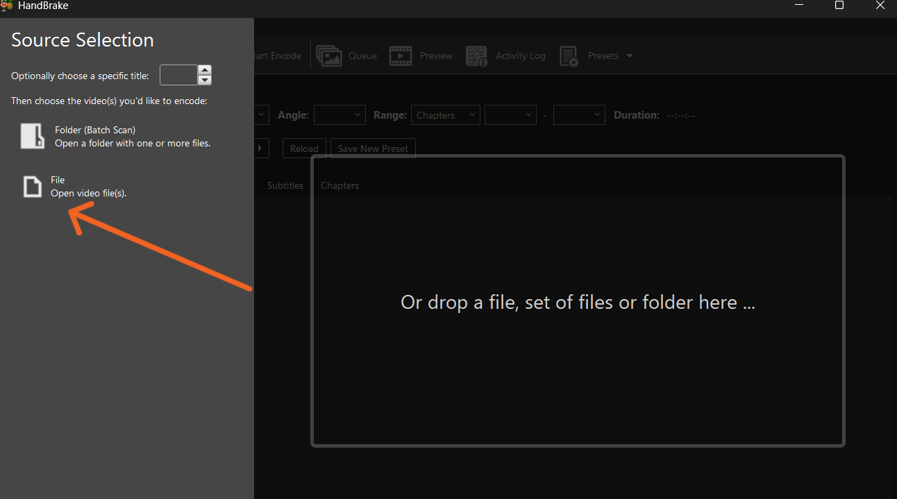
To reduce the size of my videos, for videos, I used HandBrake. This tool was recommended to me by Mariam Daghbashyan, a Fab Academy Dilijan student, who also helped me become familiar with the program’s main features and settings.
First, I downloaded and installed HandBrake. After opening the program, I clicked File and selected the video I wanted to compress.
Then, I configured the encoding settings by choosing the H.264 (x264) encoder, setting the framerate to 30 FPS, and selecting Constant Quality RF 20 as the quality setting.
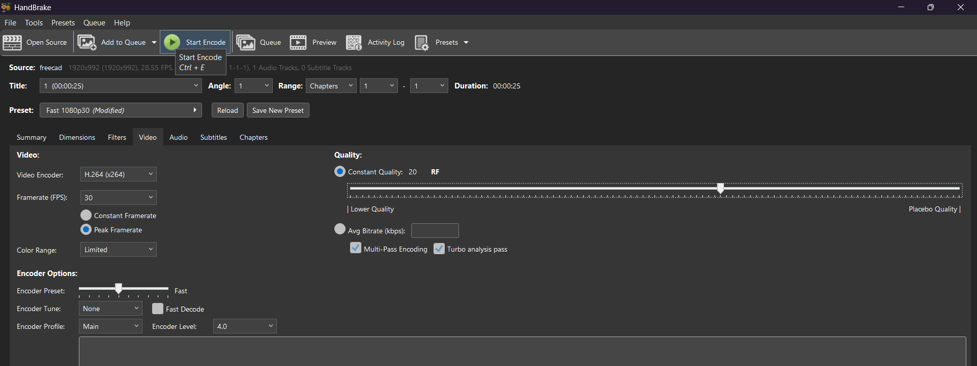
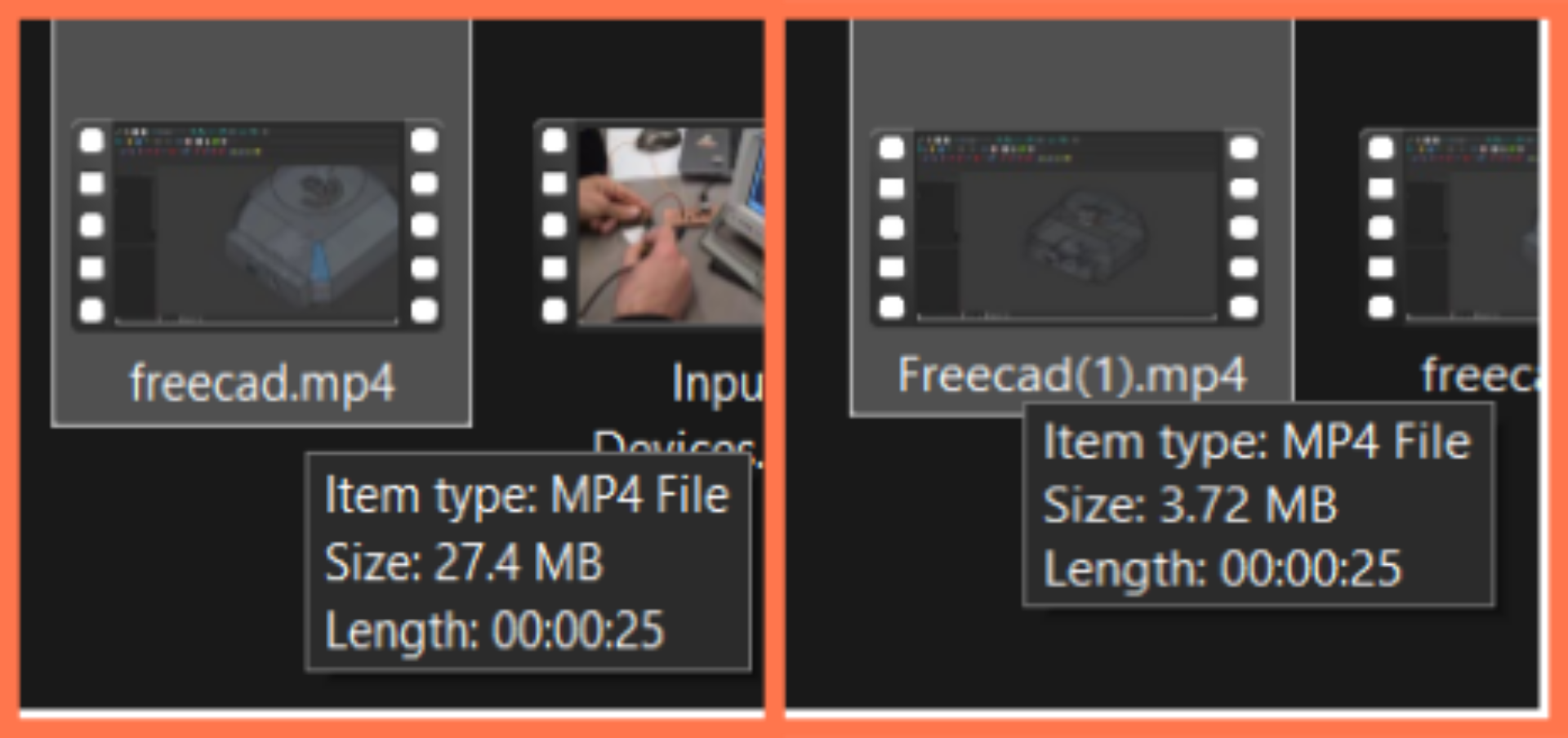
I experimented with several different settings to find the most suitable option for my documentation. Before compression, the video file size was 27.4 MB. After testing different parameters, I selected the settings that significantly reduced the file size while maintaining acceptable visual quality.
Then I started the encoding process by clicking the Start Encode button. The video was processed in a short time and automatically saved to the selected output folder after completion.
After compression, the video file size was reduced from 27.4 MB to 3.72 MB, while still maintaining acceptable visual quality. This significant reduction made the video much more suitable for web upload and documentation purposes.
After testing different encoding parameters, I selected the settings that best reduced the file size without noticeably affecting the video quality.
2D Softwares.
AI Illustrator
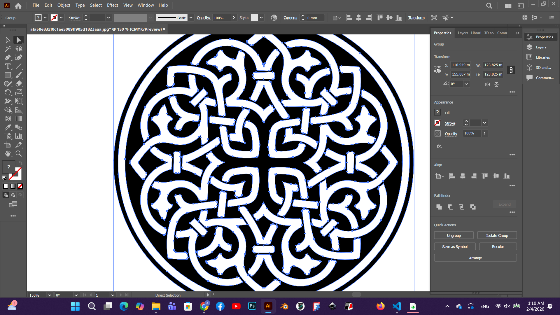
Adobe Illustrator (AI) is a vector graphics software designed for creating lines, shapes, and precise designs. It works with mathematical vectors, which allows the graphics to maintain their quality when scaled up or down. Illustrator is widely used for creating drawings, diagrams, and production-ready files, especially for laser cutting and CNC machines.
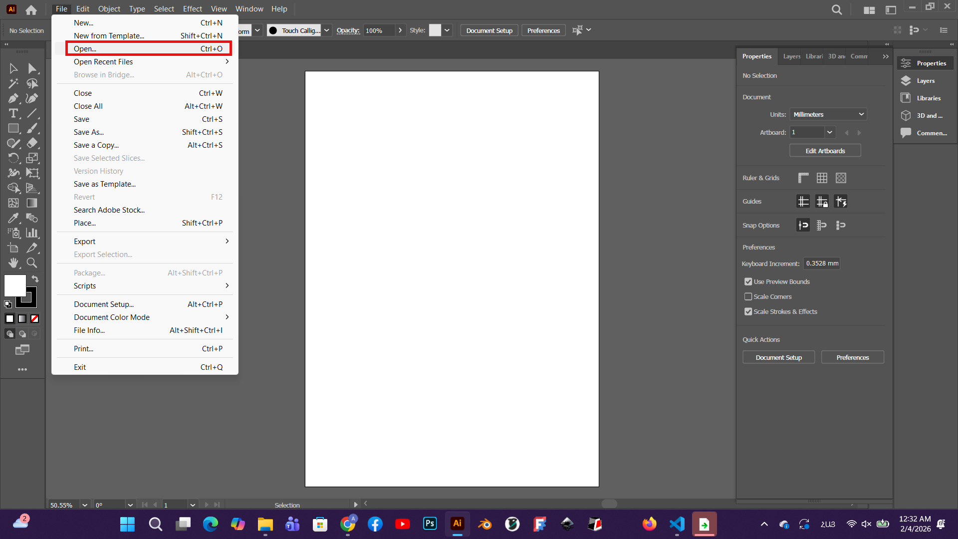
I wanted to create a digital vector logo for my university. This vector logo can then be used for laser cutting, engraving, and manufacturing. This will allow for high quality and accurate results, regardless of size.
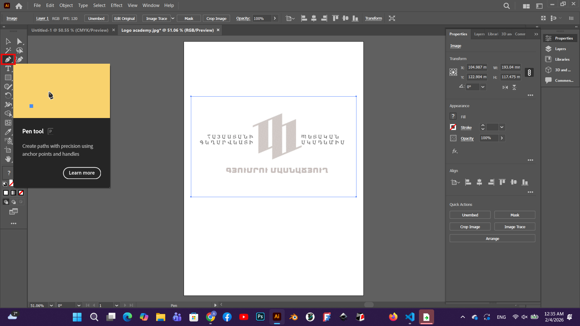
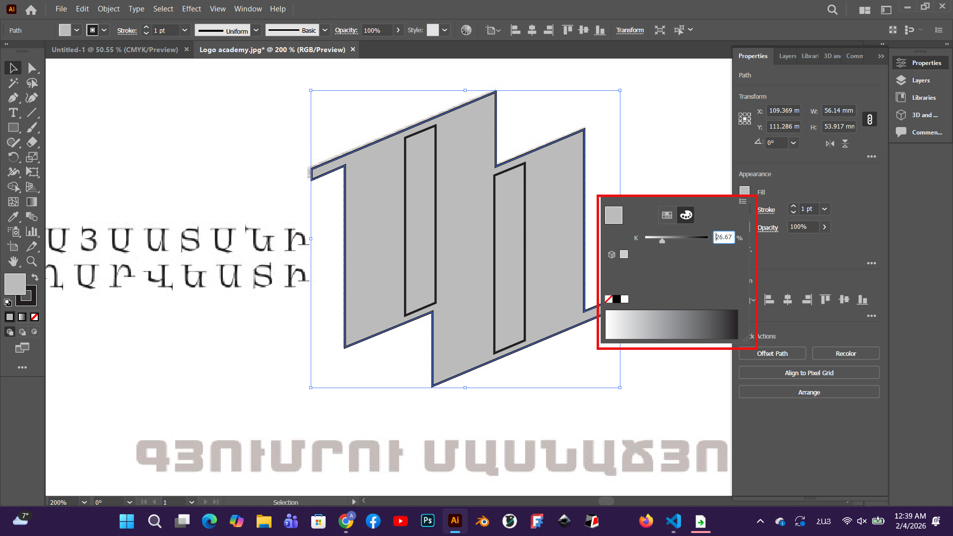
I opened Adobe Illustrator and imported my image into the workspace for further illustration.
I started working on the image using the Pen Tool, tracing the main shapes and lines through vector drawing.
Then, using the Fill tool, I applied appropriate colors to the created vector details, highlighting the shape and structure of each section.
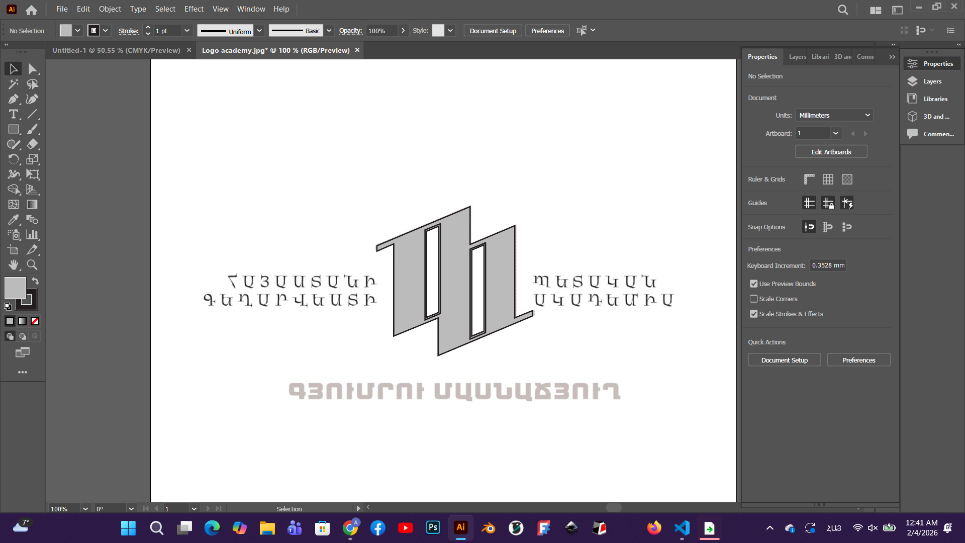
As a result, we obtained a vector version of my image.
This was the first method used to obtain a vector file.
Using the second method, this process can be done more easily.
First, the image is imported, and then.
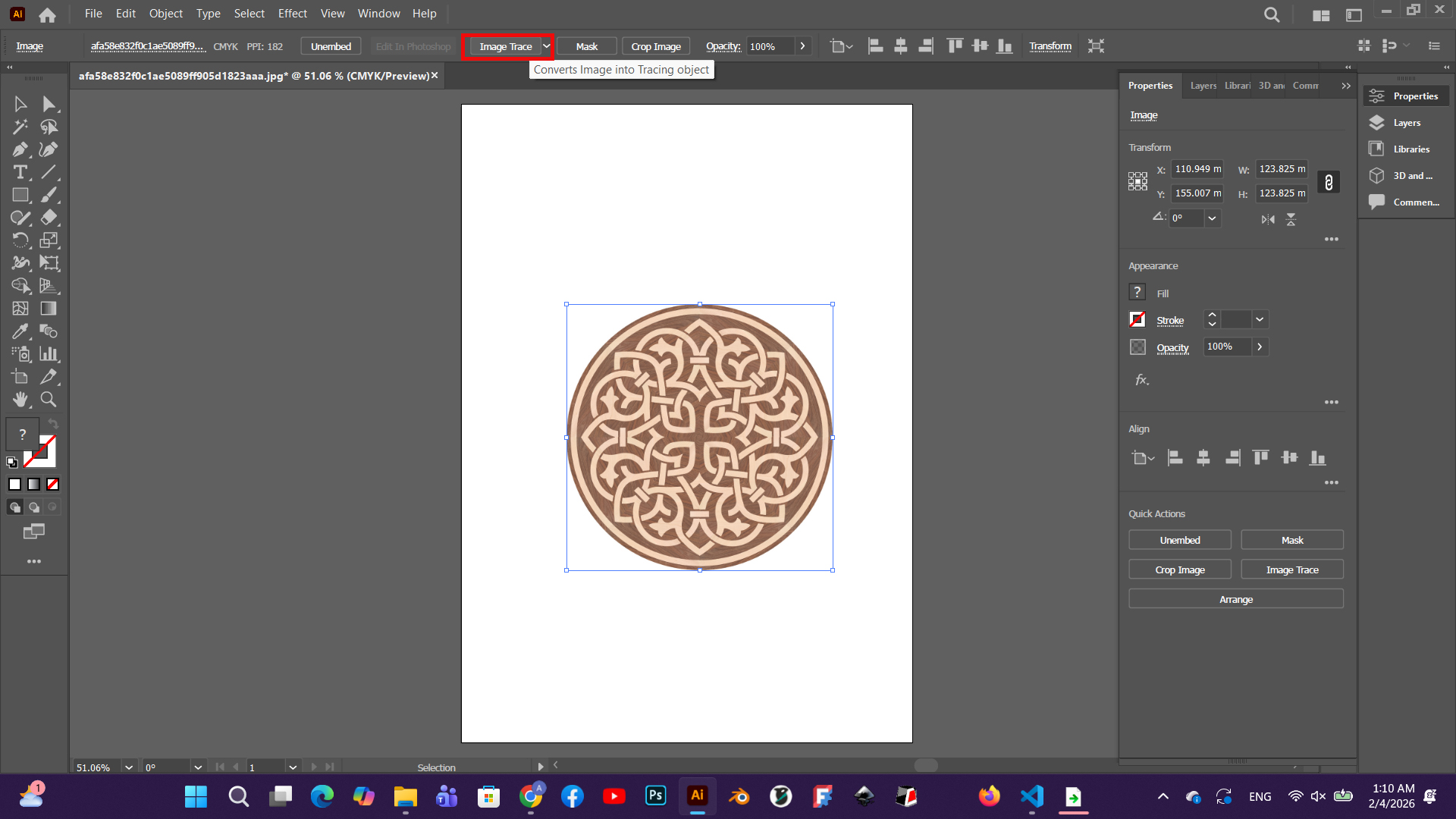
using the Image Trace tool, it is immediately converted into a vector, which allows working directly with anchor points.
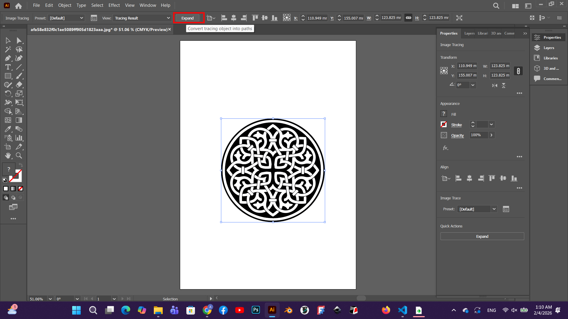
which allows working directly with anchor points.
Photoshop
Adobe Photoshop is a software designed for working with raster graphics. It is mainly used for image editing, manipulation, and composition creation. Photoshop works with pixel-based images, making it suitable for photo retouching, texture creation, color correction, and detailed visual work.
I opened my selected image in Adobe Photoshop.
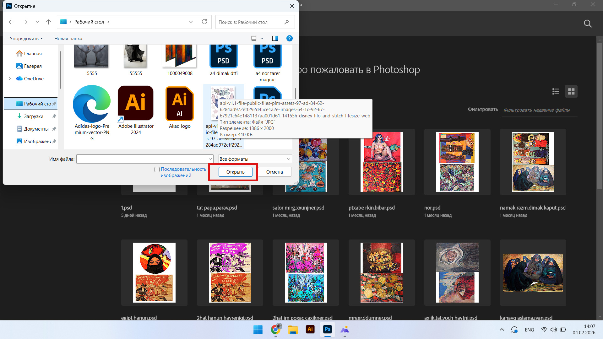
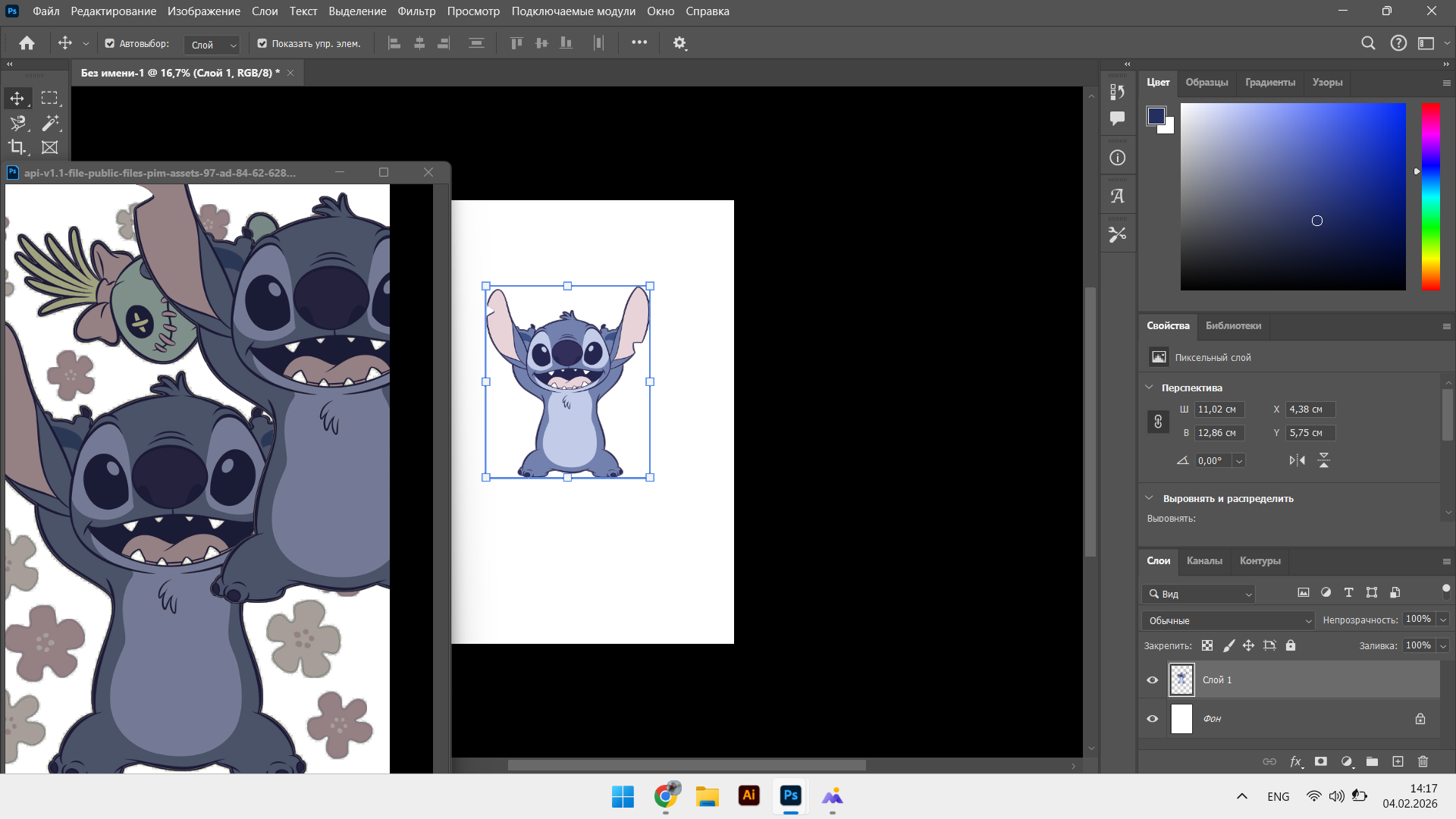
Using the first method, I selected the required area of the image with the Magnetic Lasso Tool,
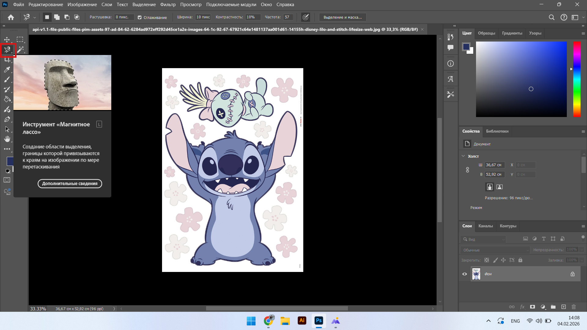
and then used Ctrl + J to separate the selected part from the background onto a new layer.
3D Modeling in FreeCAD
3D LEGO Design
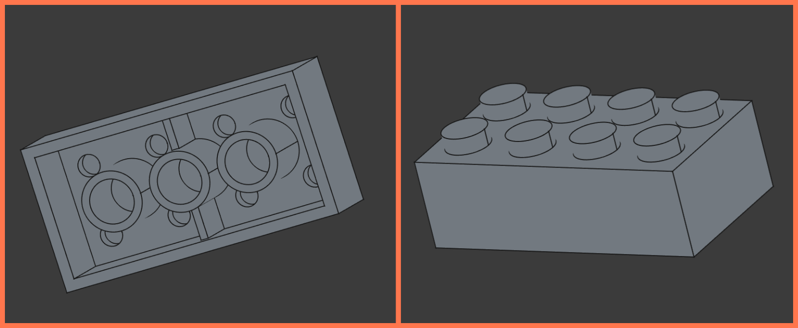
This week I worked in the FreeCAD program. Since I was not familiar with this program before, I first watched a tutorial video to get acquainted with the program environment, main tools and workflow. Then, in order to apply the acquired knowledge in practice, I tried to reproduce the Lego model presented in the video on my own. This exercise helped me better understand the work of Sketch, Pad, MultiTransform, Thickness and other tools, as well as gain initial experience before moving on to my main project.
FreeCAD is an open-source parametric 3D modeling software. It is mainly used for engineering design, mechanical parts, architectural elements, and manufacturing objects. In FreeCAD, models are created with precise dimensions, and any modification can be made through parameters (e.g., changing dimensions) without having to rebuild the entire model. The software is suitable for CAD/CAM, 3D printing, and technical design.
Here is the video tutorial link that I used: Link
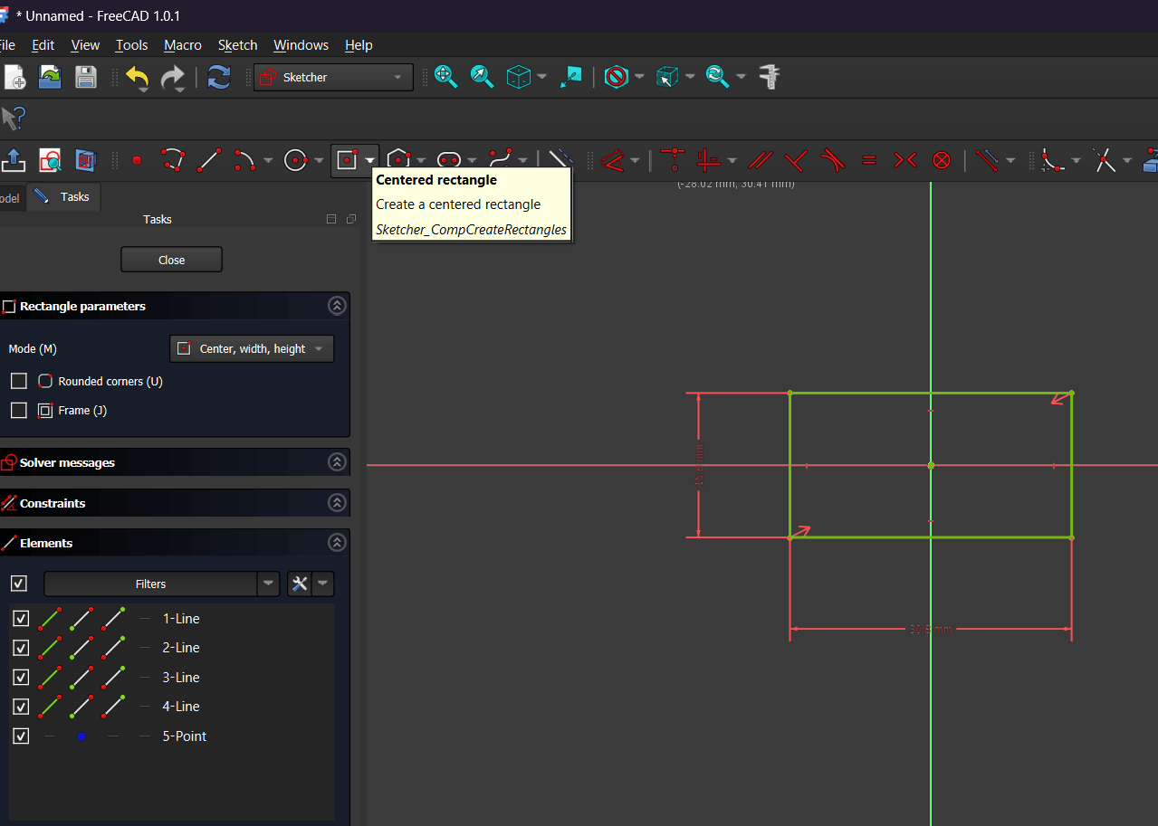
I created a new sketch in the Sketcher workbench and selected the Centered Rectangle tool. I drew a rectangle centered relative to the axes and defined its width and height using dimensional constraints.
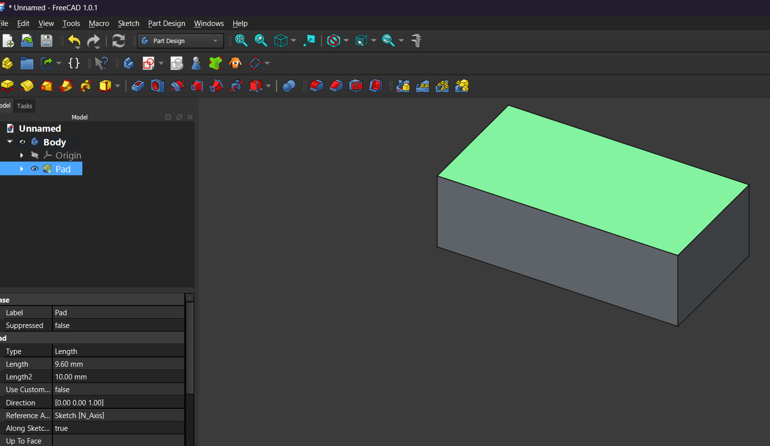
After finishing the sketch, I exited it and used the Pad tool in the Part Design workbench to give the rectangle volume. This produced a rectangular prism as the base body.
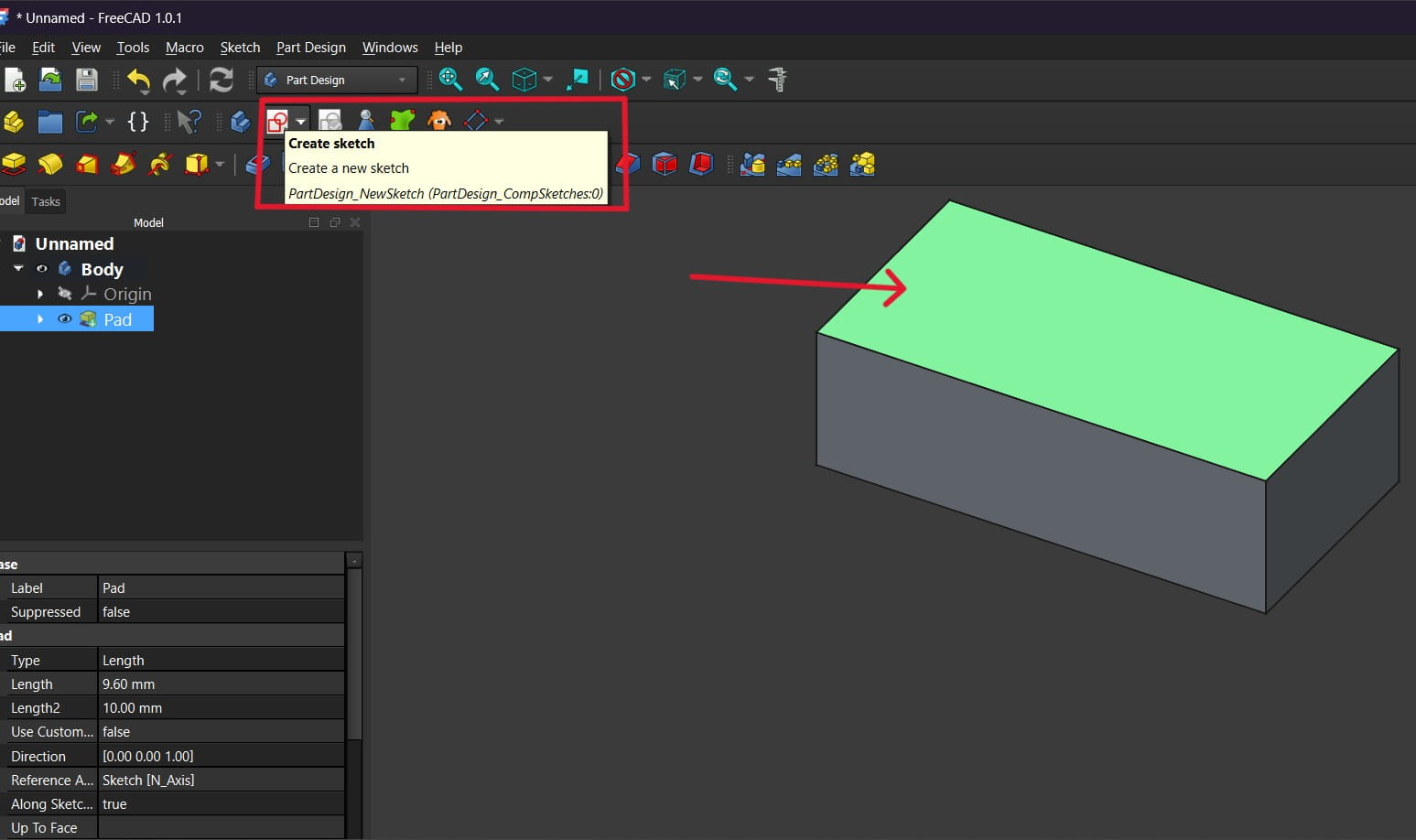
I selected the top face of the body and clicked Create Sketch to make a new sketch on that surface.
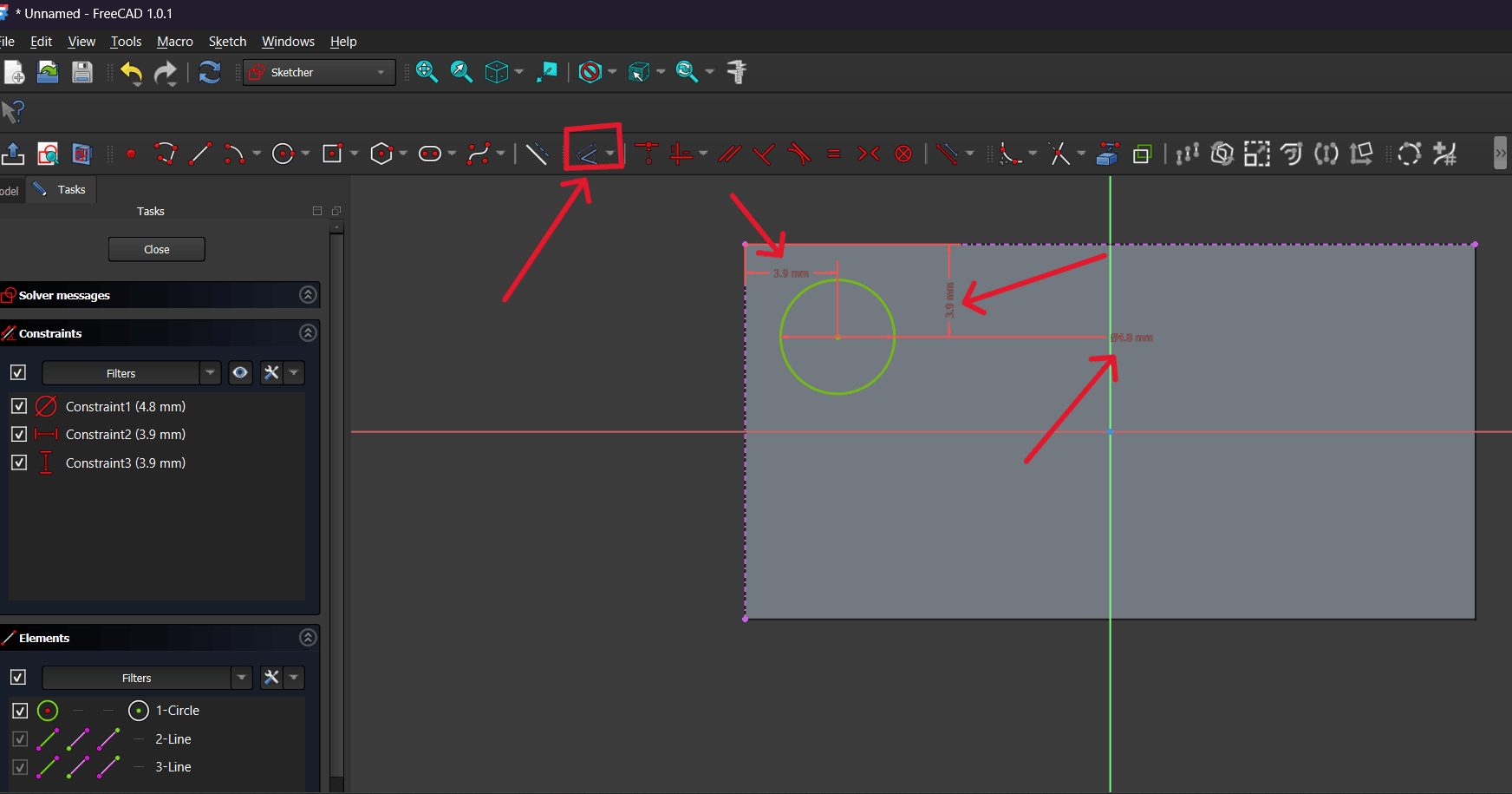
In the new sketch, I created a circle and defined its position and diameter using constraints so that it was precisely placed on the surface.
I closed the sketch and again applied the Pad tool to raise the circular profile. As a result, a cylindrical protrusion appeared on the main body.
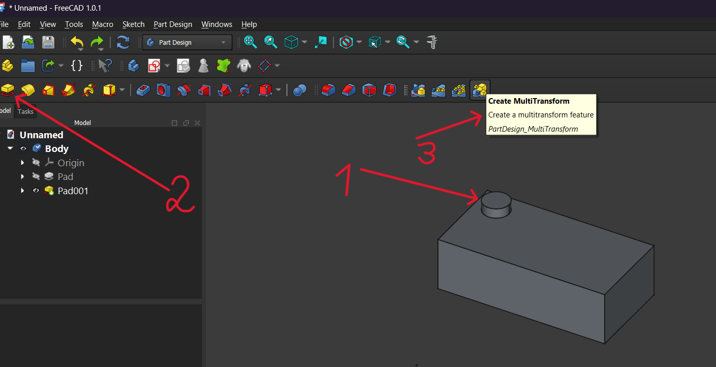
I selected the created cylinder and activated the MultiTransform tool to duplicate the feature.
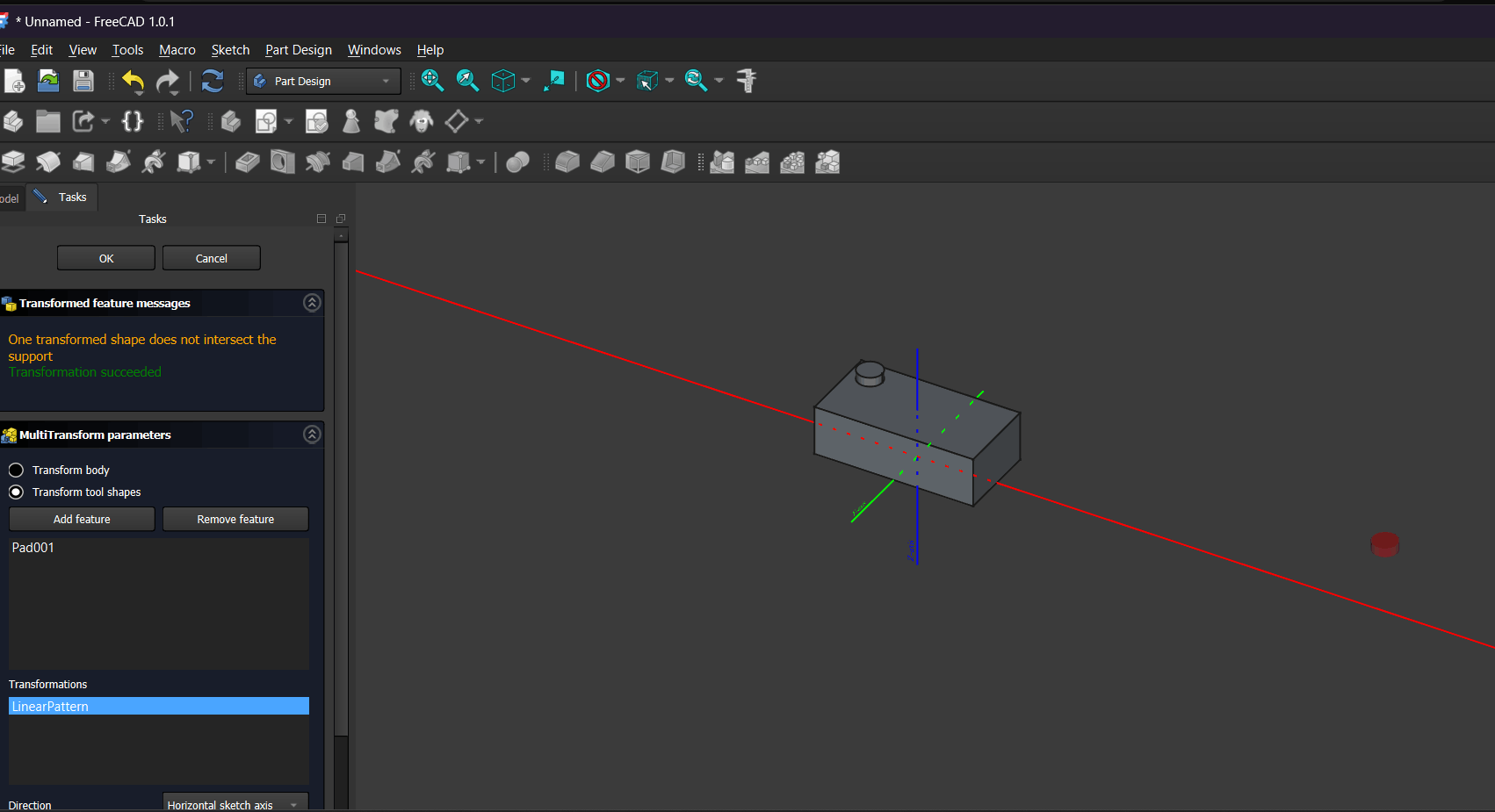
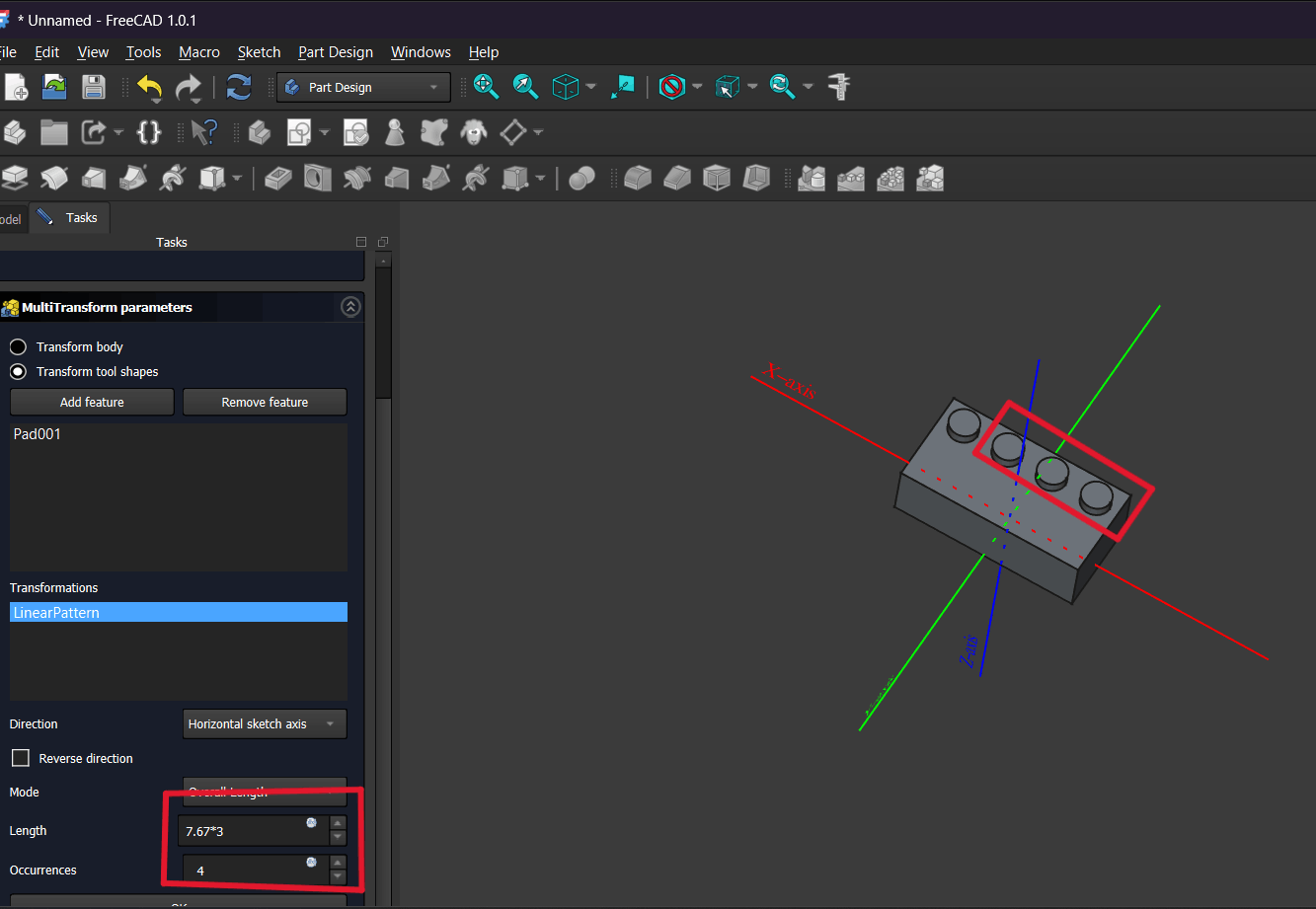
Inside MultiTransform, I chose Linear Pattern, set the direction (Horizontal sketch axis), the step length, and the number of occurrences so the cylinders would be arranged in one direction.
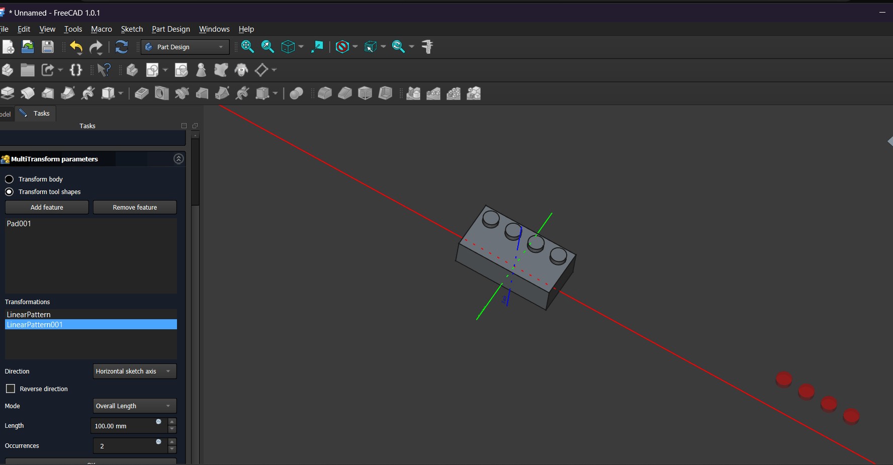
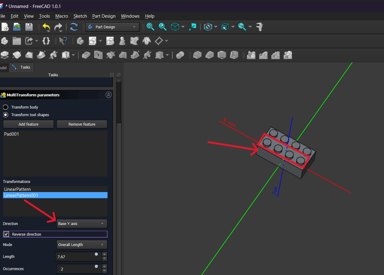
I added a second Linear Pattern, selected another direction (Base Y axis), optionally enabled Reverse direction, and set the length and repetition count to obtain a grid arrangement of protrusions.
As a result of these steps, a rectangular body was created with evenly distributed cylindrical protrusions on its top surface using Sketch, Pad, and Linear Pattern tools.
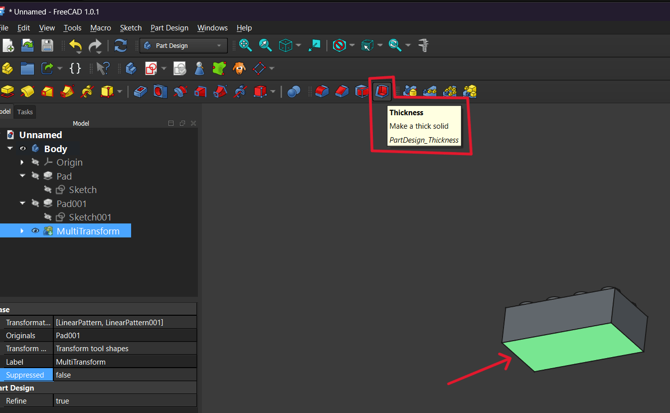
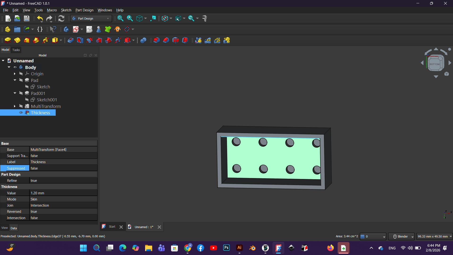
I selected the bottom face of the body and activated the Thickness tool to hollow the solid.
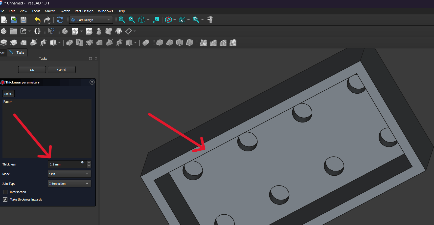
In the Thickness settings, I set the wall thickness to 1.2 mm and selected Make thickness inwards so the offset would be applied toward the interior.
In the Join Type parameter, I chose the appropriate option (e.g., Intersection or Arc) to ensure proper edge formation and smooth transitions.
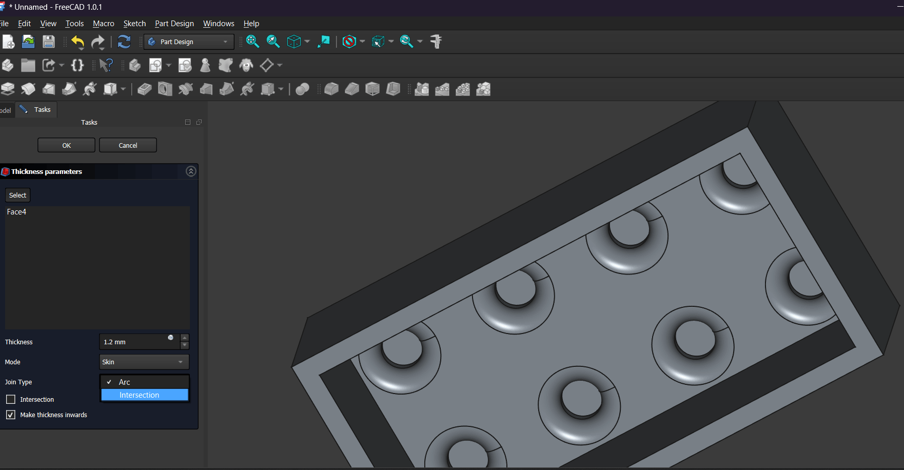
After applying Thickness, the result was a hollow body with an internal surface suitable for creating additional features.
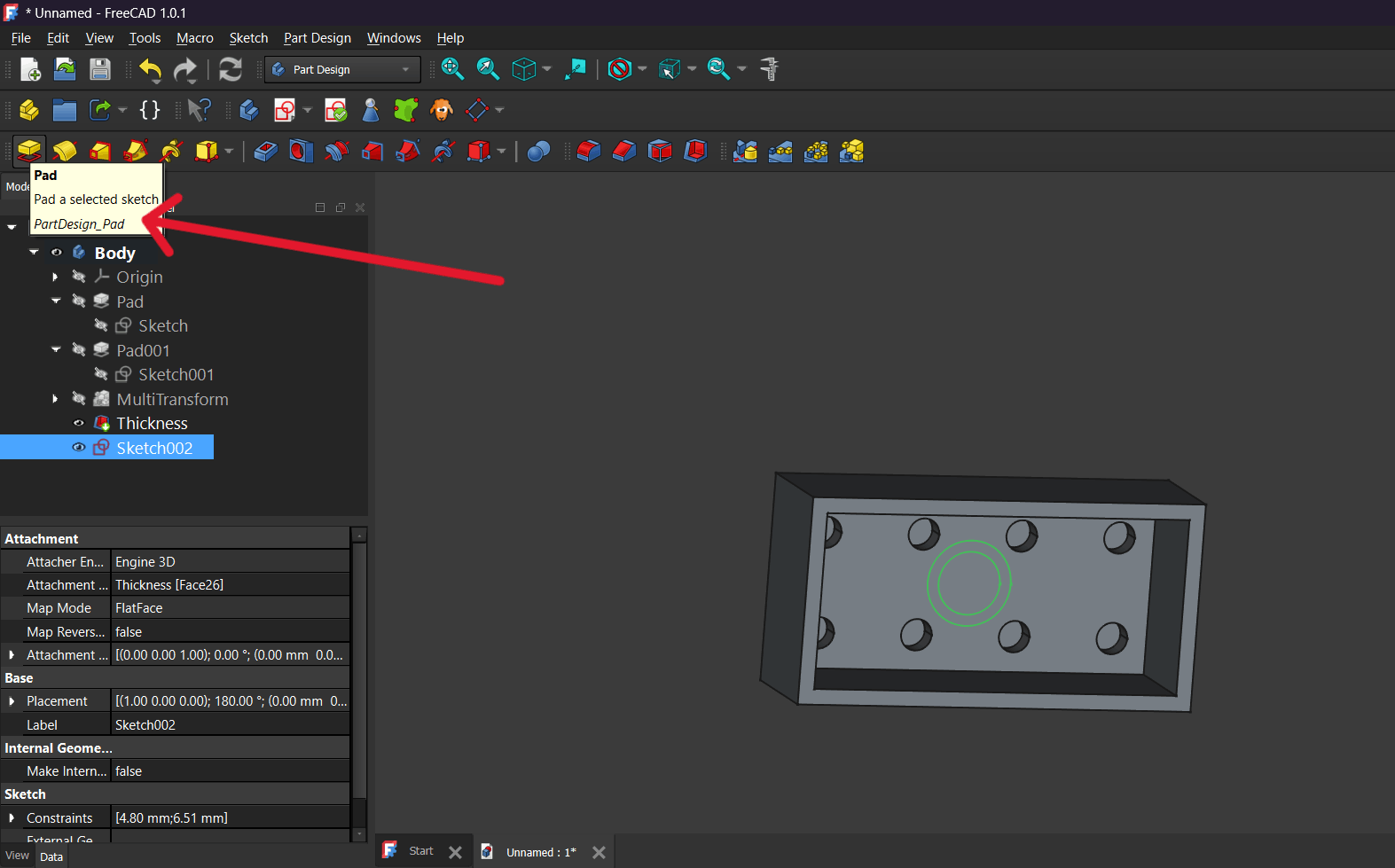
I selected the inner bottom face and clicked Create Sketch to start a new sketch on that surface.
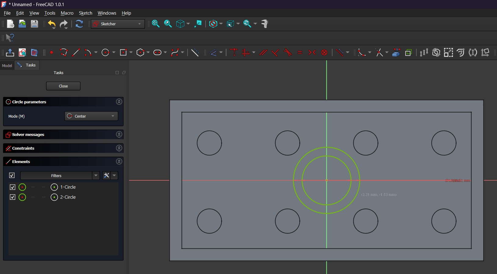
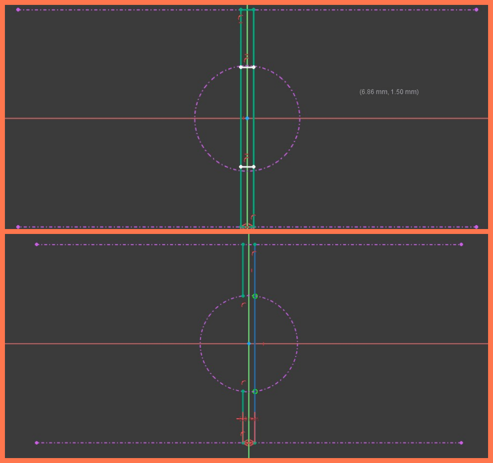
In the sketch, I used the Circle tool to draw two concentric circles and applied constraints to keep them centered relative to the axes and to precisely define their diameters.
I added vertical and coincident constraints to properly position the sketch elements relative to the reference axes, then used the Trim tool to remove unnecessary segments.
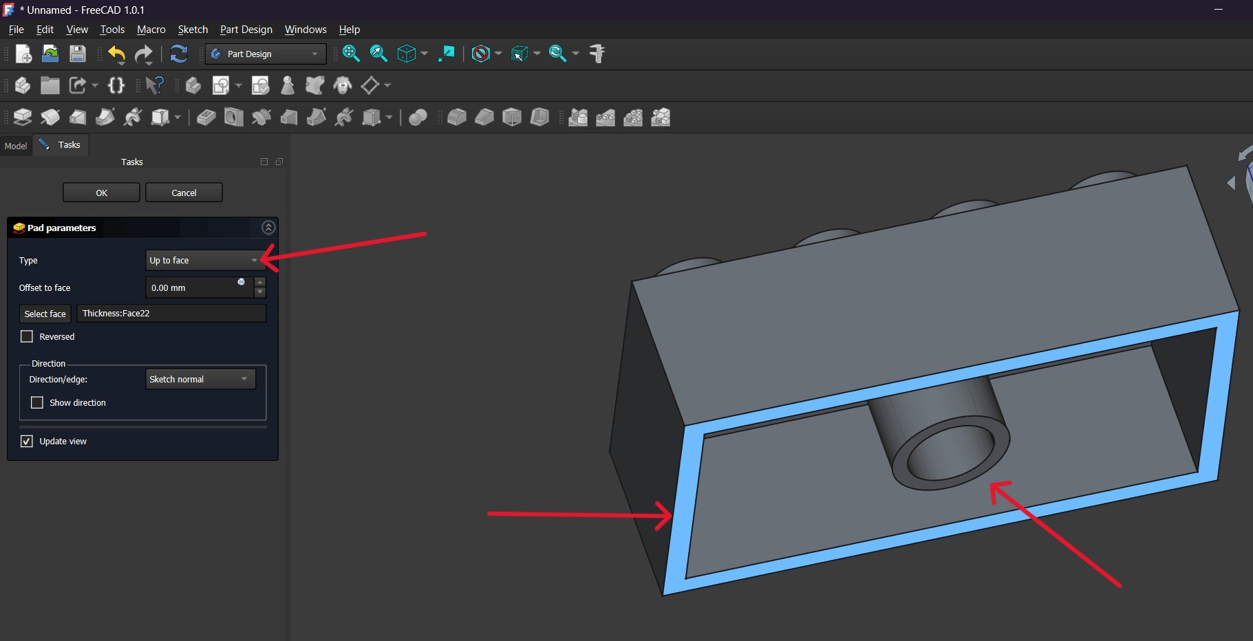
I closed the sketch and applied the Pad tool, setting Type → Up to face, so the cylindrical feature would extend until it reached the upper internal surface.
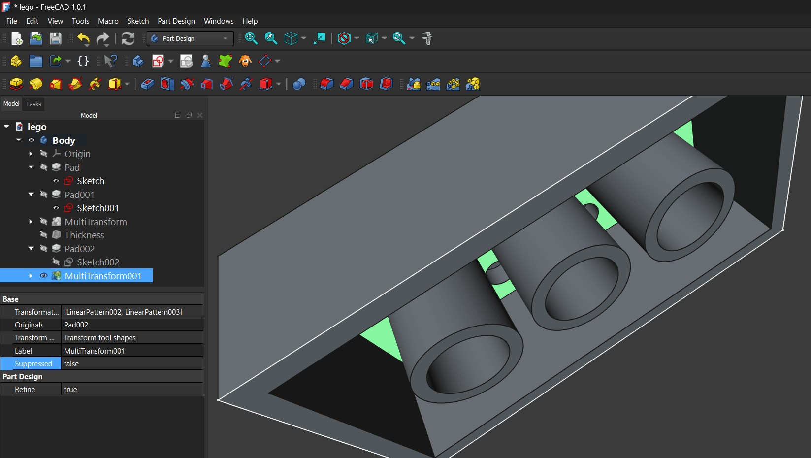 To duplicate the cylinder, I used MultiTransform → Linear Pattern, defining the direction, offset distance (e.g., 7.67 mm), and number of occurrences.
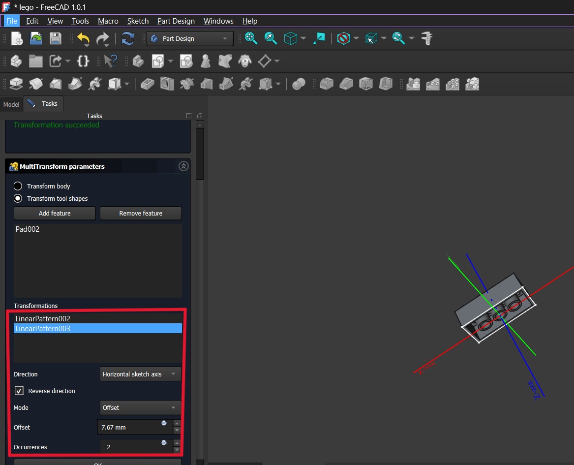
I added a second Linear Pattern in another direction so the cylinders would form a grid-like arrangement across the inner surface.
Finally, I defined the cylinder height (e.g., 6.3 mm) and obtained the finished model with a repeated internal cylindrical structure and a complete external form.
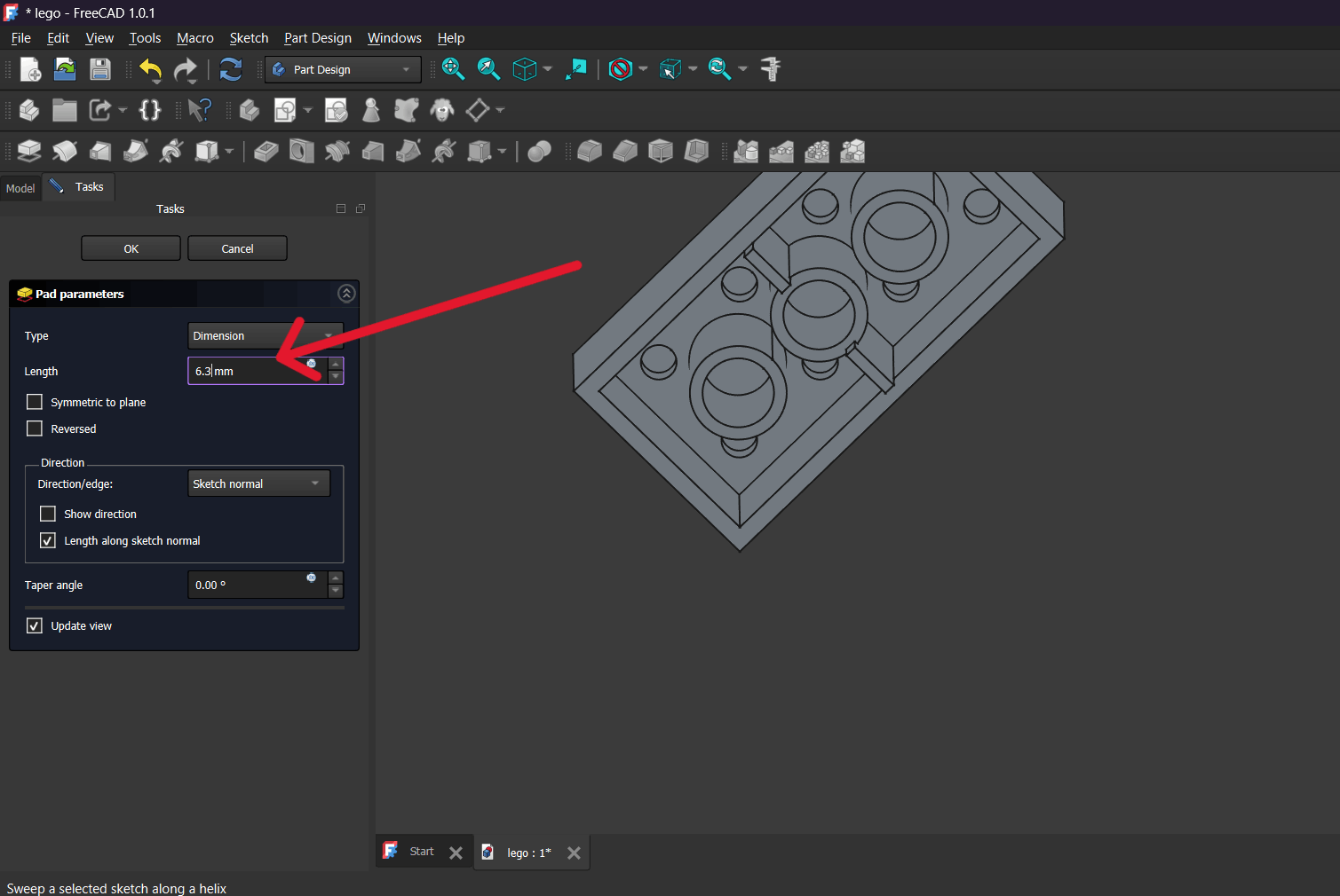
This is the final model obtained after completing all operations.
Final Project Design
After completing the practice exercise, I moved on to designing and assembling a component directly related to my final project.
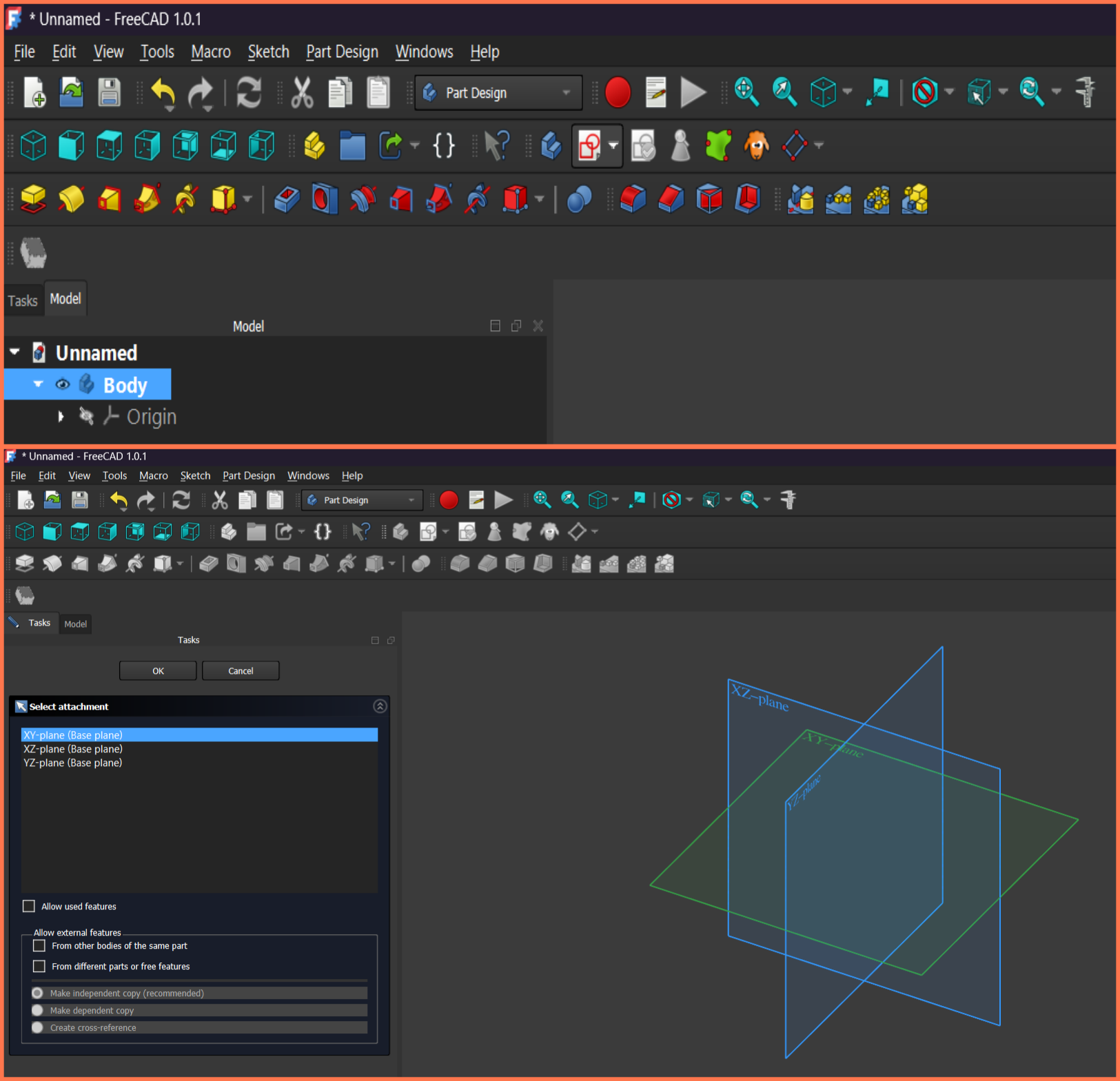
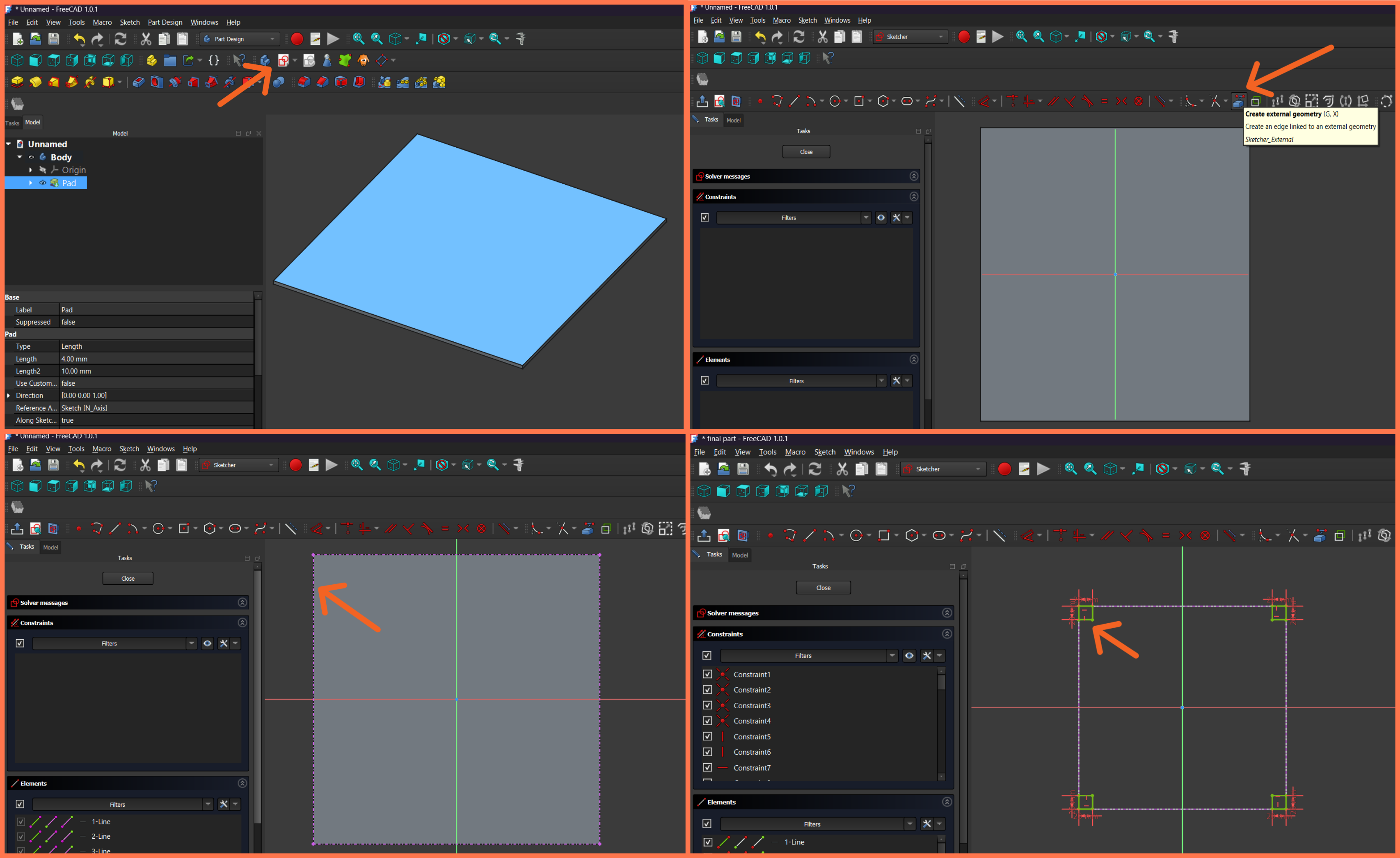
I opened a new window, created a new project in the Part Design workbench, added a Body, and started a new Sketch by selecting the XY plane as the working surface.
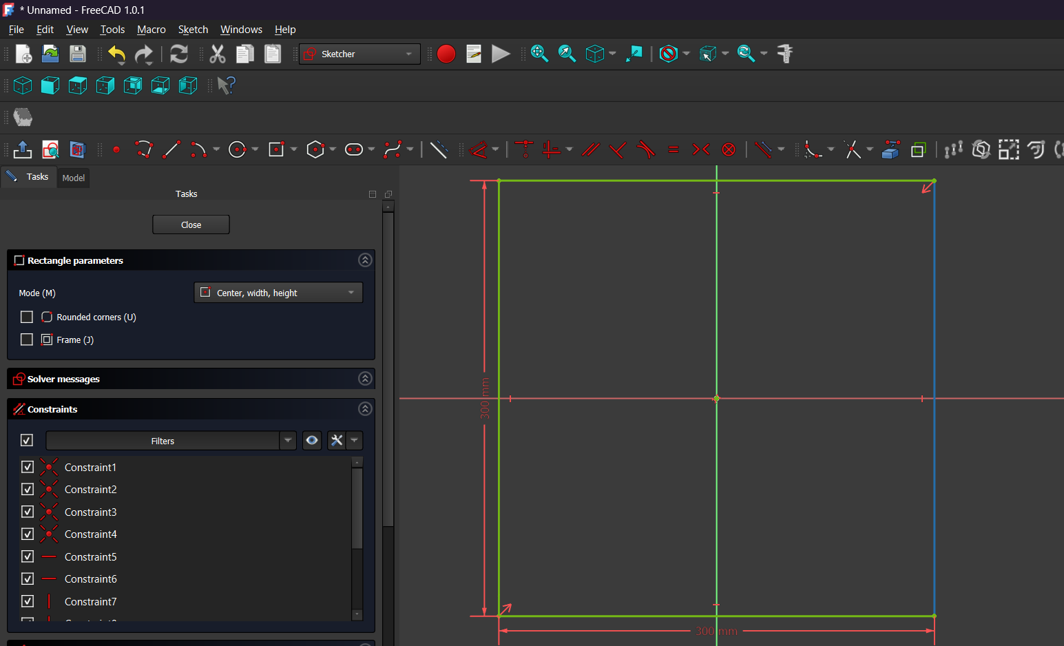
In the Sketcher environment, I drew a 300 × 300 mm rectangle and applied the necessary constraints to fully define the sketch.
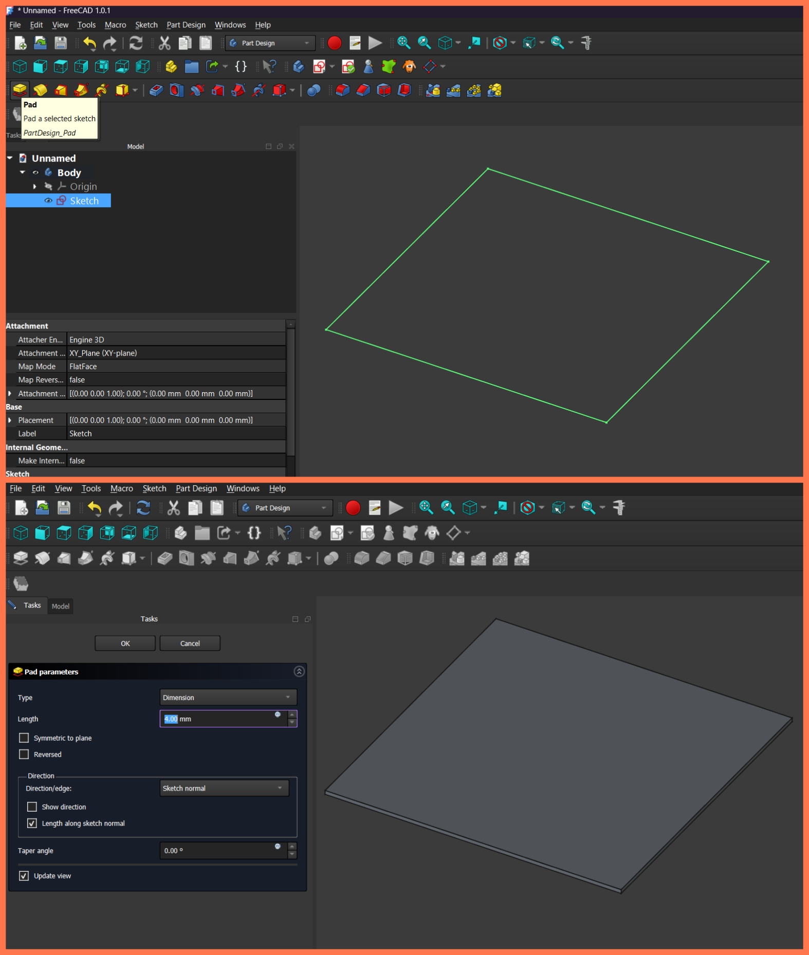
After completing the sketch, I exited the Sketcher environment and selected the created sketch to convert it into a three-dimensional object.
I then used the Pad tool and set the thickness to 4 mm, resulting in a 300 × 300 × 4 mm 3D flat plate intended to serve as a structural component of my final project.
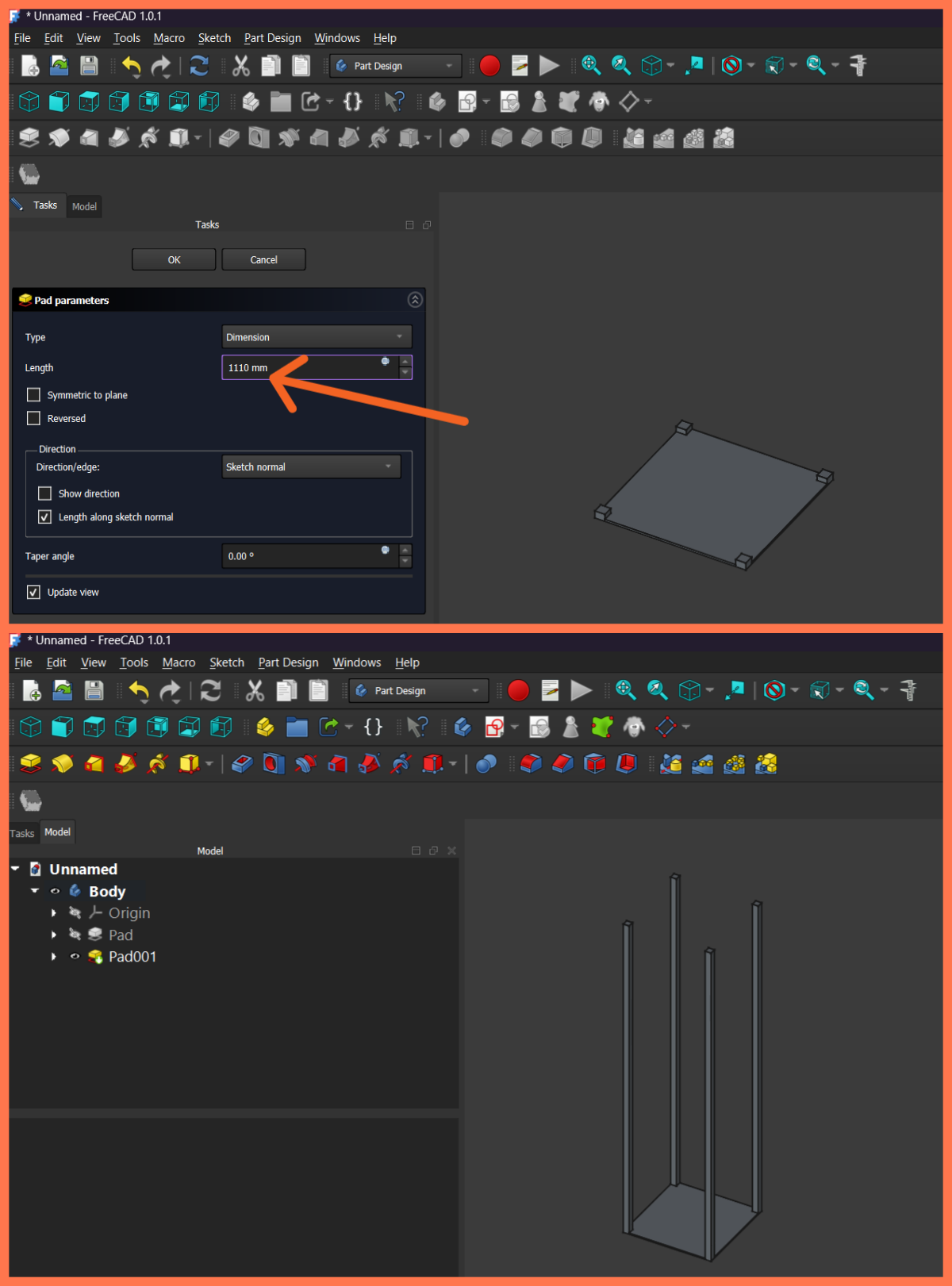
After creating the bottom plate, I selected its top surface and created a new Sketch to define the positions of the vertical supports. In the Sketcher environment, I drew four small square profiles near the corners of the plate and applied the necessary geometric and dimensional constraints to accurately define their positions.
After fully constraining the sketch, I exited the Sketcher environment and used the Pad tool to convert the square profiles into three-dimensional bodies. I set the extrusion length to 1110 mm, resulting in four vertical supports extending upward from the bottom plate.
As a result, the main supporting structure was formed, consisting of the bottom plate and four vertical columns.
Next, to create the upper section, I selected the top surfaces of the vertical supports and created a new Sketch. In the Sketcher environment, I used the External Geometry tool to import the existing edges as references, which allowed the new sketch to be accurately aligned with the rest of the structure.
After completing the sketch, I once again used the Pad tool and set the thickness to 4 mm. As a result, the top plate of the structure was created, connecting all four vertical supports and giving the main frame a finished appearance.
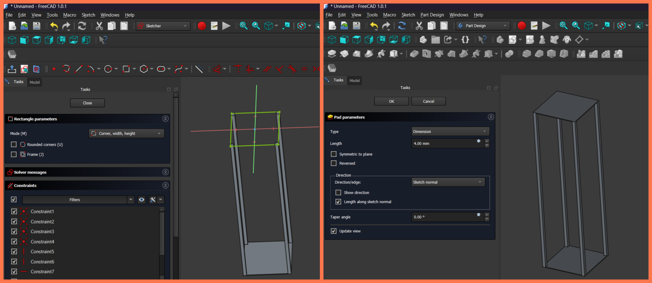
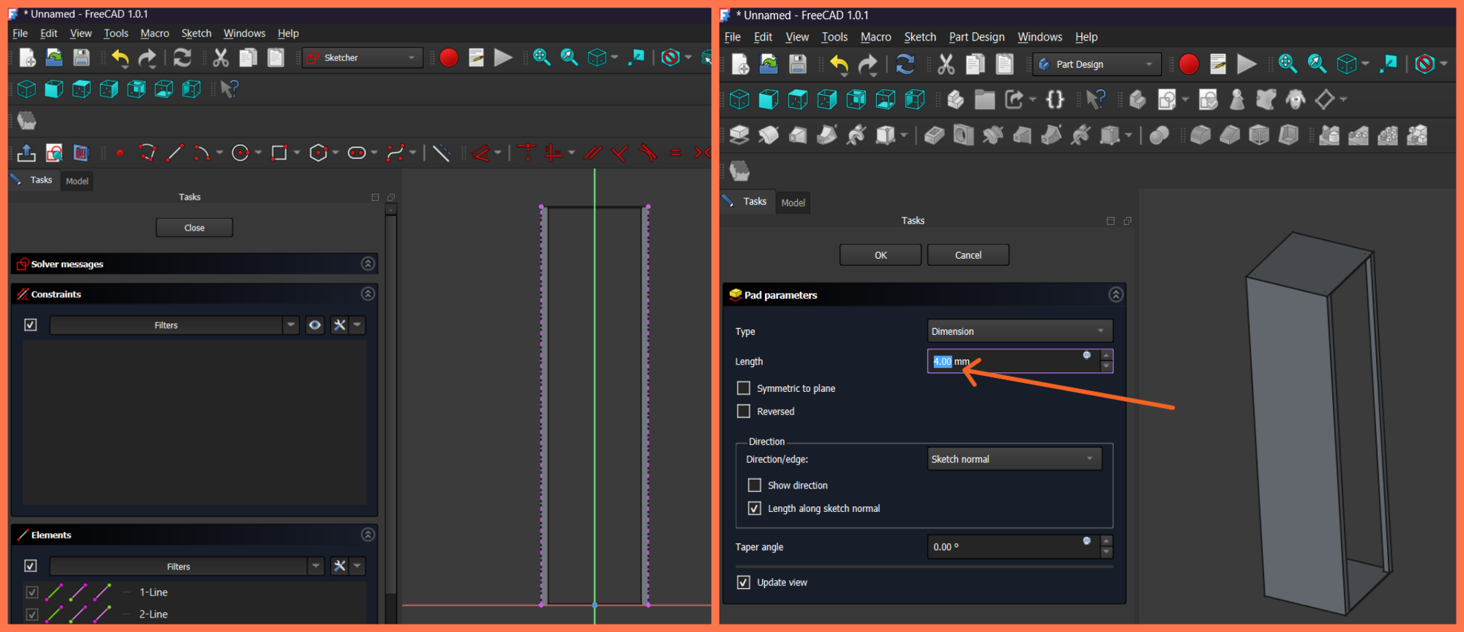
After creating the top plate, I proceeded with the design of the outer walls of the structure. To do this, I selected the appropriate working plane and created a new Sketch. In the Sketcher environment, I drew a rectangular profile corresponding to the outer dimensions of the structure and applied the necessary constraints to fully define the sketch.
After exiting the Sketcher environment, I used the Pad tool and set the thickness to 4 mm. As a result, one of the side walls of the structure was created, enclosing the open frame and giving the enclosure a more complete appearance. I repeated the same procedure for the remaining three sides, resulting in a complete outer enclosure consisting of four side walls.
Next, I proceeded to create openings on the front panel. I selected the outer surface of one of the side walls and created a new Sketch.
In the Sketcher environment, I drew a single rectangle with dimensions of 150 × 100 mm. I then copied the same profile and applied the appropriate dimensional constraints to obtain three evenly spaced rectangular openings.
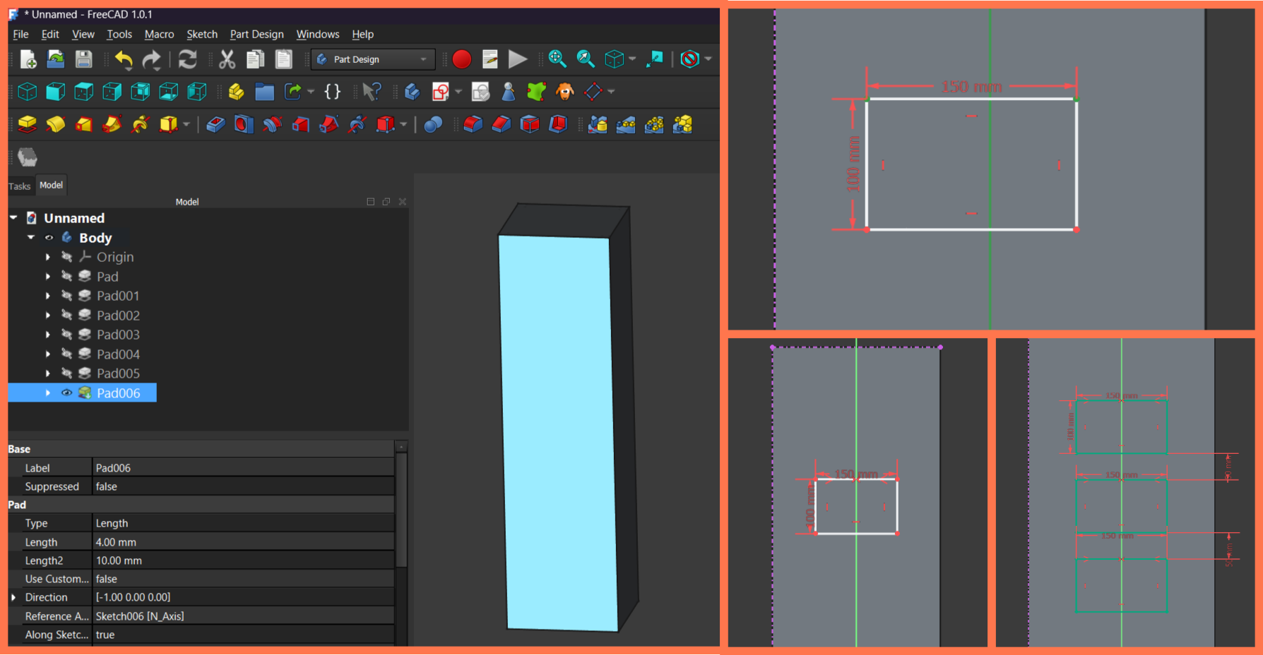
These rectangular profiles were intended for mounting the LED matrix displays used in the project, so their dimensions and positions were defined according to the dimensions of the selected components. The arrangement of the openings was designed to ensure both proper installation of the displays and an aesthetically pleasing overall appearance of the device.
I positioned the openings with respect to the central vertical axis, ensuring accurate alignment and the required spacing between them.
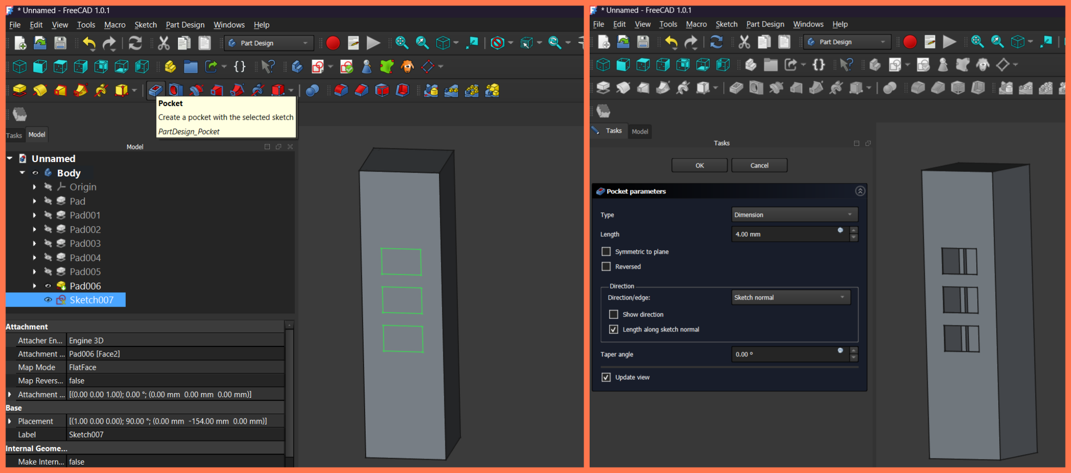
After completing the sketch, I exited the Sketcher environment and used the Pocket tool. In the Pocket parameters, I set the depth to 4 mm, corresponding to the thickness of the panel. As a result, the rectangular sections were removed from the body, creating three openings for the LED matrix displays.
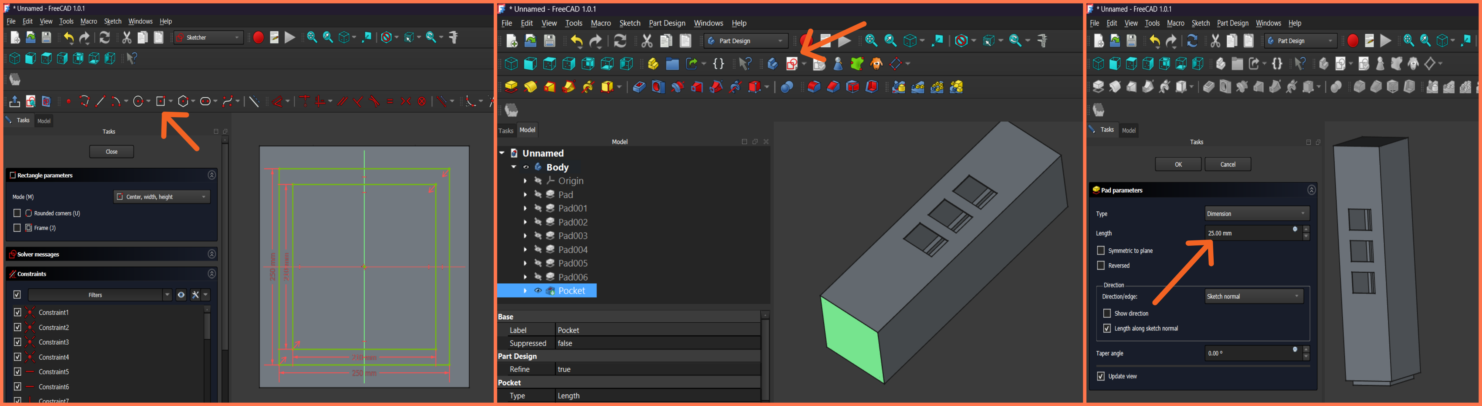
Next, I created an additional feature at the bottom of the structure to give the enclosure a more complete and aesthetically pleasing appearance. To do this, I selected the appropriate face and created a new Sketch. In the Sketcher environment, I drew two concentric square profiles and applied the necessary constraints to ensure their accurate positioning.
After completing the sketch, I exited the Sketcher environment and used the Pad tool, setting the extrusion length to 25 mm. As a result, an additional feature was created at the bottom of the structure, improving the overall appearance of the enclosure and giving it a more finished look.
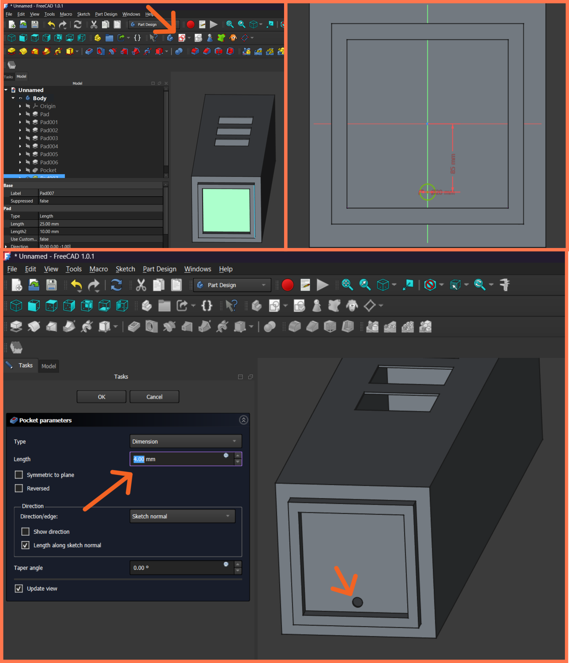
Next, I selected the outer surface of this newly created feature and created a new Sketch. In the Sketcher environment, I drew a small circular profile and defined its position using the appropriate dimensional constraints. After completing the sketch, I exited the Sketcher environment and used the Pocket tool to create a hole intended for routing the electrical wires of the entire system. The resulting opening allows the power and connection cables to be routed in an organized manner.
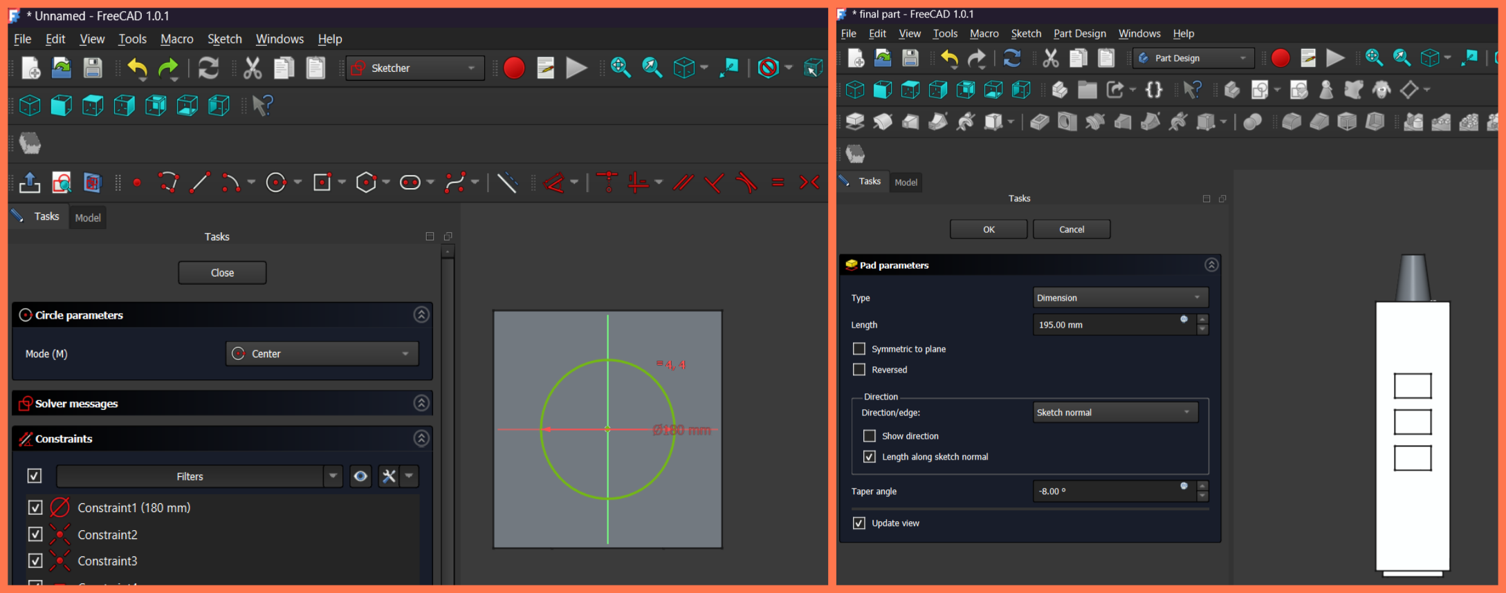
Then, I created a conical element on the upper part of the structure to give the corpus a more complete and aesthetic appearance. For this, I selected the top surface and created a new sketch.
In the Sketcher environment, I drew a circle with a diameter of 180 mm and positioned it relative to the central axis of the structure by applying the necessary constraints.
After completing the sketch, I exited the Sketcher environment and used the Pad tool. I set the extrusion length to 195 mm and applied a −8° taper angle using the Taper angle parameter. As a result, a conical body was created and placed on the upper part of the enclosure, giving the structure a more interesting and finished external appearance.
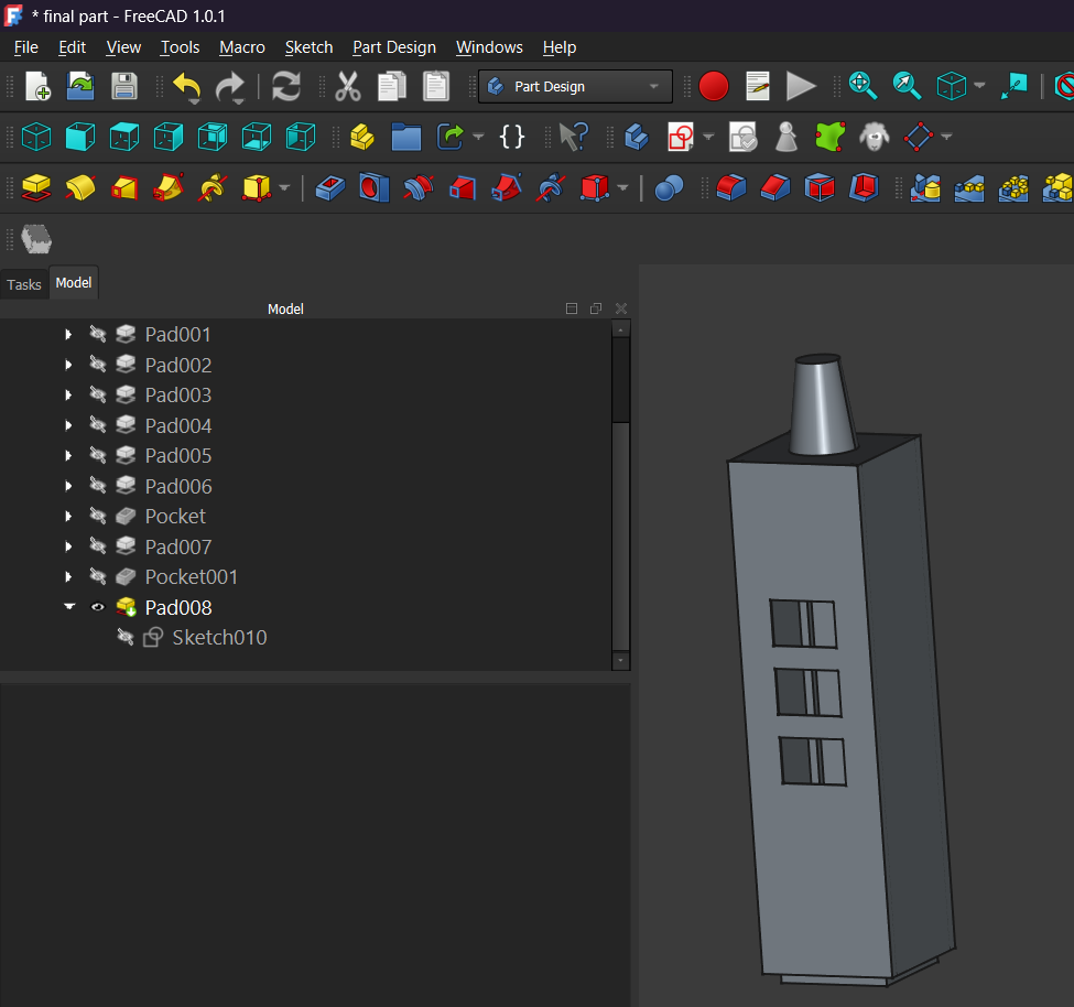
This is the column section of my final project, and I plan to model the upper main section in the coming weeks.
Rendering the Model in Blender
Blender is a free and open-source 3D graphics software used for 3D modeling, animation, simulation, visualization, and rendering. It is widely used in various fields, from design and architecture to game development and film production.
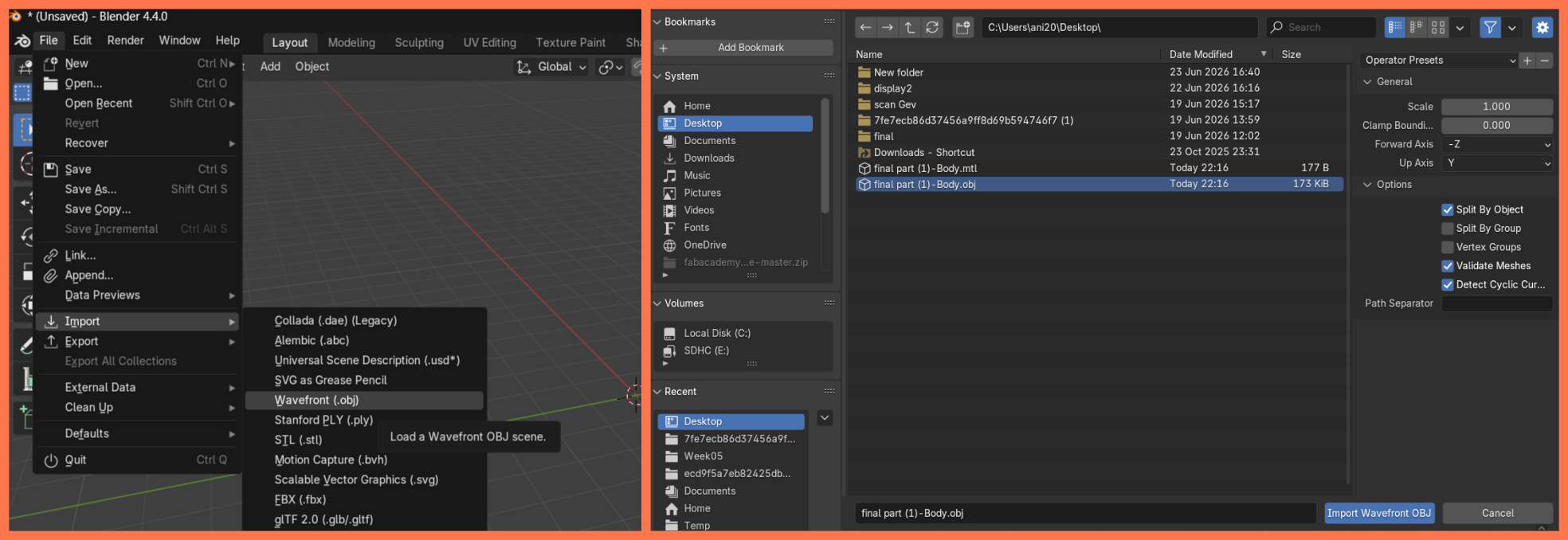
After completing the design of the model in FreeCAD, I exported it in OBJ format and imported it into Blender to create a more realistic visualization of the project.
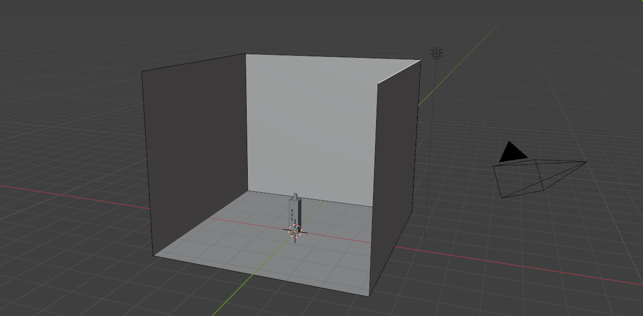
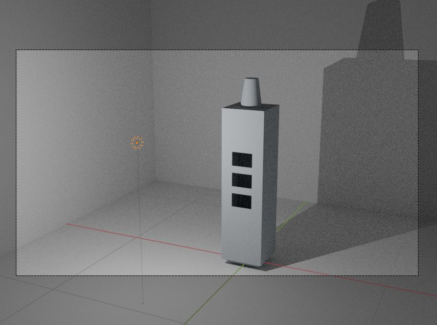
After importing the model into Blender, I positioned it at the center of the scene and adjusted its orientation. Next, I created three vertical planes around the model to serve as the background. I assigned a dark material to these planes to make the model stand out from the background and give the final render a more professional appearance.
Next, I assigned a metallic material to the model by adjusting the Metallic and Roughness parameters, giving the enclosure a realistic metallic appearance. I then added a light source to the scene and adjusted its position and intensity to produce soft shadows and natural reflections on the surface of the model. After that, I positioned the camera to clearly capture both the front and side views of the enclosure, providing a better presentation of the overall structure.
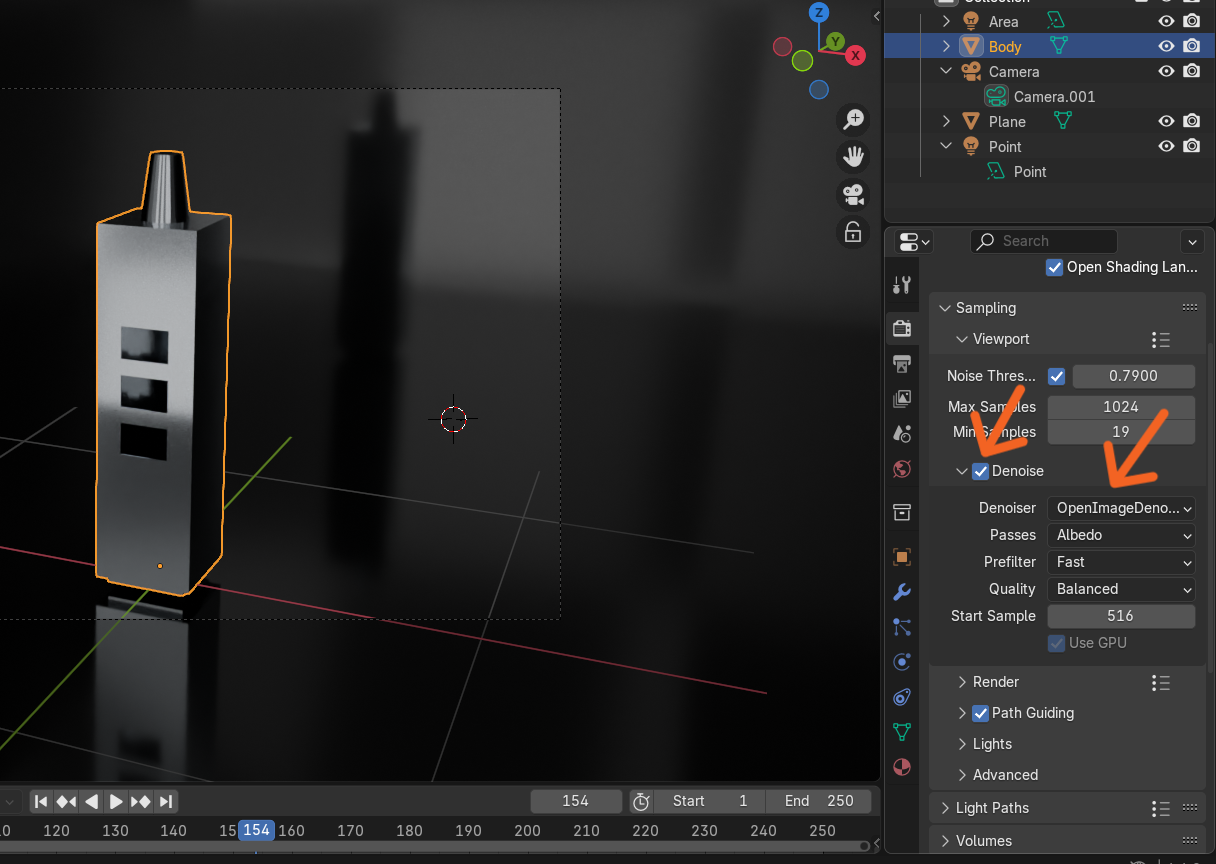
For the rendering process, I selected the Cycles render engine and enabled GPU Compute to improve rendering performance and image quality. I also enabled OpenImageDenoise to reduce image noise and set a high Max Samples value. These settings significantly reduced noise in the rendered image and produced a cleaner, sharper, and higher-quality final result.
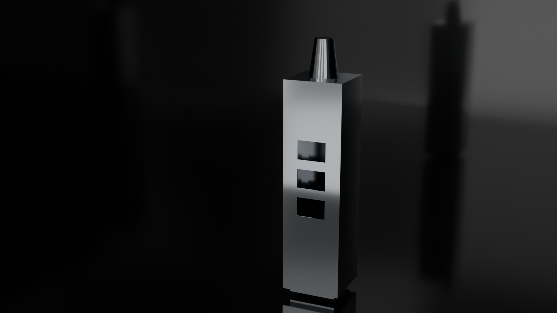
Finally, I rendered the scene and obtained a high-quality visualization of the project. The final render provides a realistic representation of the enclosure’s appearance, selected materials, lighting, and overall design, allowing the project to be evaluated before physical fabrication.
Conclusion
In conclusion, this week I explored several software tools used in the digital design workflow. I worked with both vector and raster graphics software, learned how to optimize images and videos for documentation, and became familiar with the basic workflow of FreeCAD. After completing a practice exercise, I designed the first structural section of my final project in FreeCAD, gaining practical experience with sketching, applying constraints, creating 3D features, and assembling a complete CAD model.
To improve the presentation of the design, I exported the model to Blender, where I assigned materials, created a simple scene with background planes, adjusted the lighting and camera, configured the rendering settings, and produced a realistic render of the model. Overall, this week’s work strengthened my skills in both CAD modeling and 3D visualization, providing a solid foundation for the continued development and presentation of my final project.