Week 4. Embedded programming
Group Assignment
This week we completed a group assignment related to microcontroller programming. The goal of the week was to understand how a microcontroller works, how to write and upload a program, and how to study the operation of input and output pins.
We explored different development boards and microcontroller platforms, specifically Arduino Uno (ATmega328P), XIAO RP2040, and STM32, along with their main features. During the group work, we compared different development environments and programming workflows used for each platform, including Arduino IDE for Arduino Uno and XIAO RP2040, and STM32CubeMX with VS Code for STM32.
We conducted an experiment using the RP2040 microcontroller to study the fundamental principles of its programming. We wrote the required code, uploaded it to the device, and tested the built-in RGB LED by producing blinking lights in different colors.
Throughout this process, we became familiar with program structure, the compilation and uploading workflow, and the practical use of microcontroller input/output pins, which helped us better understand how microcontrollers operate.
The full documentation and results of the group assignment can be viewed at the following link: Group Assignment Link
Toolchain Comparison
| Dev Board | Toolchain | Programming Language | Workflow |
|---|---|---|---|
| Arduino Uno (ATmega328P) | Arduino IDE | C/C++ (Arduino framework) | Simple setup, select board and port, compile and upload directly via USB |
| Seeed Studio XIAO RP2040 | Arduino IDE | C/C++ (Arduino framework) | Similar to Arduino UNO, requires installing the RP2040 board package before uploading |
| STM32F3 Discovery | STM32CubeMX + VS Code (GCC toolchain) | C (HAL / low-level) | More complex workflow: configure peripherals, generate code, build, flash, and debug |
Reflection
During the group assignment, I learned that embedded programming involves more than simply writing code. Each microcontroller platform has its own development workflow, or toolchain, which includes setting up the programming environment, selecting the correct board and communication port, compiling the code, uploading the firmware, and testing the result.
By comparing different platforms, I observed that Arduino IDE provides a simple and beginner-friendly workflow, making rapid prototyping easy. The RP2040 offered a similar workflow but with higher performance and more memory. In contrast, STM32 required a more advanced setup using STM32CubeMX and VS Code, involving peripheral configuration, code generation, building, and debugging.
This comparison helped me understand that each toolchain offers different levels of abstraction, flexibility, and hardware control. I realized that choosing the right platform depends on the project requirements, whether the goal is fast prototyping or more advanced low-level embedded development.
Individual Assignment
Working with the Seeed Studio RP2040 board
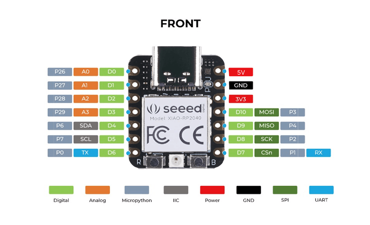
Image source: Zephyr Project Documentation, XIAO RP2040 Board Documentation.
This week, I studied the Seeed Studio XIAO RP2040 development board by reviewing its datasheet, technical documentation, and official wiki page. This helped me better understand the board’s structure, pin configuration, and how different hardware interfaces are organized.
The XIAO RP2040 is a compact development board based on the RP2040 dual-core ARM Cortex-M0+ microcontroller. Despite its small size, it offers powerful features for embedded systems projects, including a 133 MHz clock frequency, 264 KB SRAM, 2 MB flash memory, 12-bit ADC support, 11 GPIO pins, as well as I2C, UART, SPI, and PWM support.
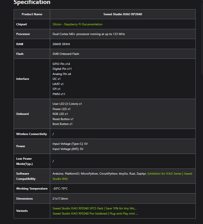
Figure 1. XIAO RP2040 specification table from official documentation
By reviewing the specification table from the datasheet, I was able to clearly identify the board’s main hardware characteristics, including processor speed, memory capacity, and supported communication interfaces. This helped me better understand the overall capabilities and limitations of the board before starting practical experiments.
From the datasheet, I also learned that the board operates at a 3.3V logic level, which is important when connecting sensors to avoid voltage mismatch or hardware damage.
During the documentation review, understanding the pin mapping was especially important, since the GPIO pins are limited and each pin can have multiple functions depending on software configuration.
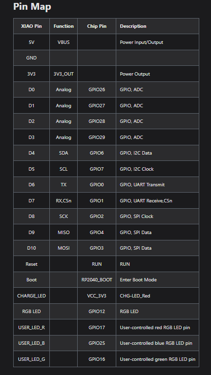
Figure 2. XIAO RP2040 pin map
The pin map section was especially useful because it showed the exact function of each GPIO pin and its alternative roles. This helped me determine which pins were suitable for analog input, digital communication, and output control in my experiments.
For analog sensors such as a potentiometer and an LDR, I used ADC-capable pins. For LED control, I used PWM-supported pins to achieve smooth brightness control.
The documentation also helped me understand how pins are related to communication protocols such as I2C, UART, and SPI, which are used for data exchange between different devices.
In practice:
- I used I2C with a DS3231 RTC module
- I used SPI-like communication with a MAX7219 LED matrix
- I used UART for debugging through the Serial Monitor
In addition, the documentation highlighted the board’s limitations, especially the number of available GPIO pins, which is important for circuit design and proper allocation of input and output connections.
Overall, studying the XIAO RP2040 datasheet and official wiki helped me better understand the board’s capabilities and design both the hardware and software parts more effectively.
Exploring the RP2040 Microcontroller Datasheet
Since the Seeed Studio XIAO RP2040 is built around the RP2040 microcontroller, I also explored the official RP2040 Datasheet published by the Raspberry Pi Foundation to better understand the architecture and operation of the microcontroller used on the development board.
The datasheet is a comprehensive technical document, so I did not read it in its entirety. Instead, I focused on the sections that were most relevant to the projects and experiments I had already completed using the XIAO RP2040.
The first section I studied was the RP2040 System Overview (Block Diagram), which presents the overall architecture of the microcontroller. From this diagram, I learned that the RP2040 includes two Arm Cortex-M0+ processor cores, on-chip SRAM, an external QSPI Flash interface, GPIO, ADC, PWM, DMA, a USB controller, and communication peripherals such as UART, SPI, and I²C. This diagram helped me understand how the different hardware modules are connected and how they work together inside the microcontroller.
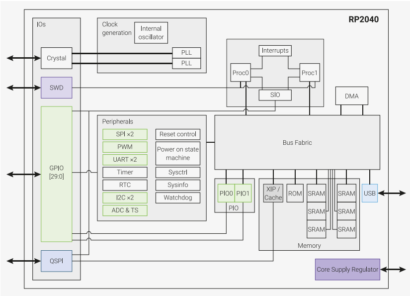
Image source: Raspberry Pi Foundation, RP2040 Datasheet.
Next, I explored the GPIO and Peripheral Functions section. This part explains that each GPIO pin can perform multiple functions depending on its software configuration. It helped me better understand why the same pin can be configured as a digital input or output, an analog input (ADC), a PWM output, or for communication through I²C, UART, and SPI. I had already used these interfaces in several assignments, but reading the datasheet gave me a clearer understanding of how they are implemented at the hardware level.
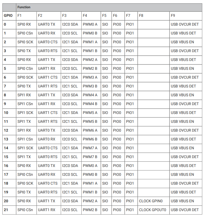
Image source: Raspberry Pi Foundation, RP2040 Datasheet.
I also studied the Bus Fabric Overview, which illustrates how the processor cores, SRAM, Flash interface, and peripherals are interconnected inside the RP2040. This diagram gave me a better understanding of how data is transferred between the different hardware modules and how the microcontroller manages communication between its internal components while executing a program.
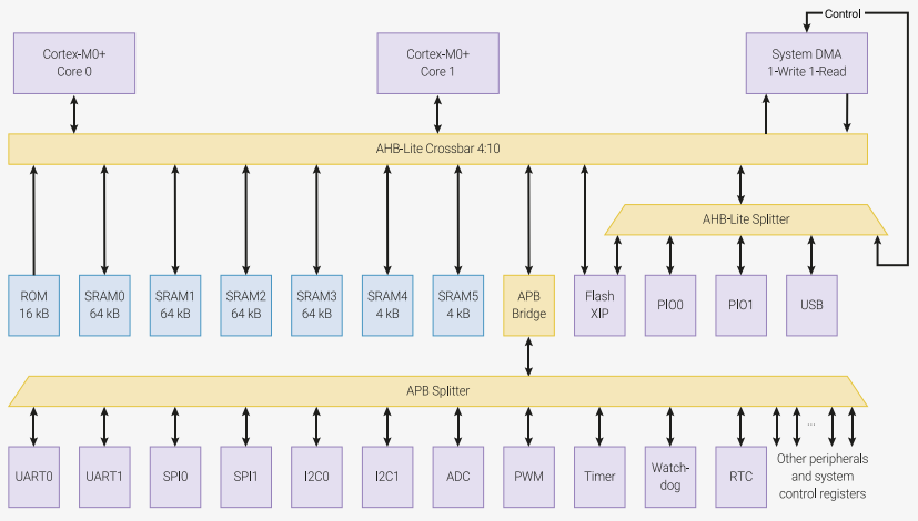
Image source: Raspberry Pi Foundation, RP2040 Datasheet.
Although I did not study every chapter of the datasheet, exploring these sections helped me connect the theoretical architecture of the RP2040 with the practical experience I gained throughout my assignments. It also gave me a much clearer understanding of how the peripherals I used—including GPIO, ADC, PWM, UART, SPI, and I²C—are implemented inside the microcontroller.
Installing the Arduino IDE
First, I downloaded and installed the Arduino IDE software. Then, I added RP2040 board support to the Arduino IDE using the Board Manager. For this, I added the following link in the Additional Boards Manager URLs field in Preferences:
https://github.com/earlephilhower/arduino-pico/releases/download/global/package_rp2040_index.json
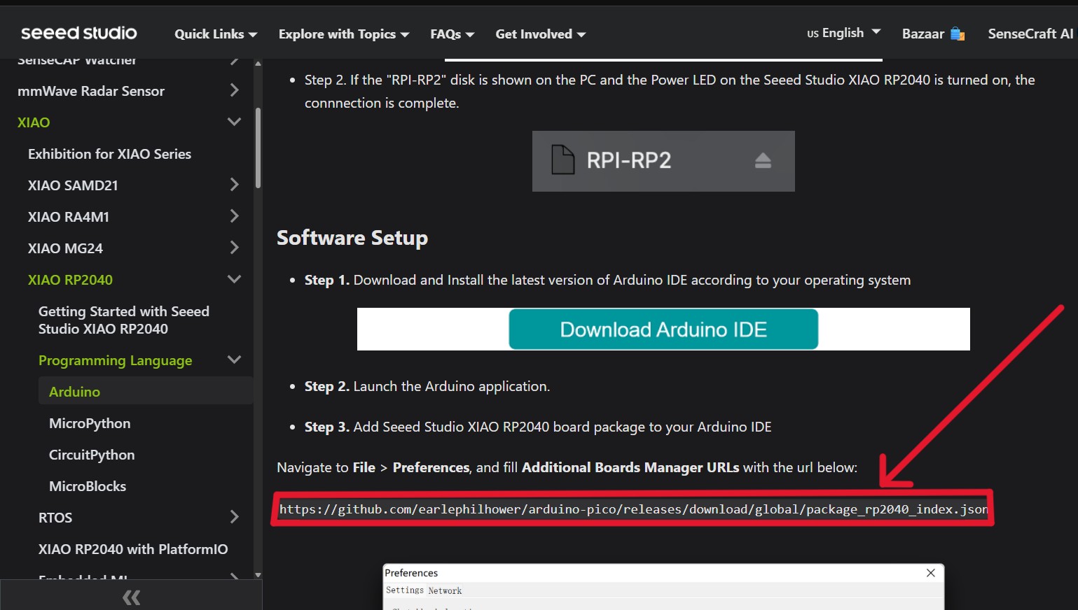
After that, I downloaded and installed the RP2040 package from the Board Manager.
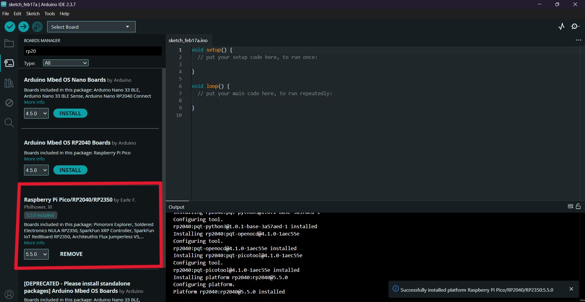
How the Arduino IDE works
It is built to operate across various operating systems.
As part of this tutorial, I experimented with the RP2040. When the program is opened, it includes two main functions։ void setup() and void loop().
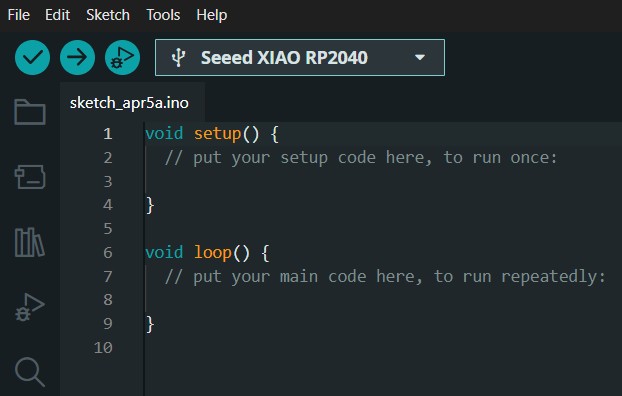
The setup() function runs only once at the beginning of the program and is used for initialization (such as setting pin modes or starting devices).
The loop() function runs continuously in a repeating cycle and contains the main logic of the program.
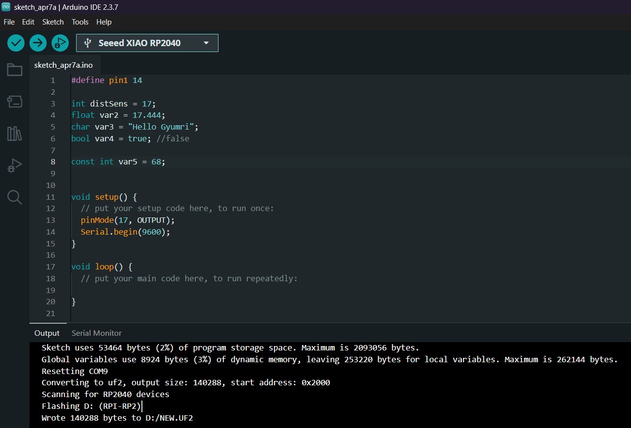
#define - The word pin1 is replaced with 14.
It does not use memory (RAM), because no variable is created, and it is a higher-level construct.
int - This variable stores an integer value. It is used for pins or for calculations.
float - This variable is used to store decimal (floating-point) numbers.
char = "Hello Gyumri" - This variable stores a string of characters (text).
A single char can store only one character (e.g., ‘A’).
To store a word or sentence, you need a character array
(char[]).
string = "Hello Gyumri"; - string is more convenient for working with text than char[] because it has built-in functions (such as concatenation, length calculation, etc.).
bool - This variable can have two values: true or false.
It is used in conditional statements.
const int - is useful for fixed values, and the value cannot be changed during the program.
pinMode(17, OUTPUT); - pinMode sets a pin as input or output.
The modes OUTPUT and INPUT allow controlling or reading the PIN, and you can use HIGH or LOW signals.
Serial.begin(9600) - This command initializes serial communication at a baud rate of 9600 bits per second, allowing the microcontroller to send and receive data through the serial port.
These fundamentals are the essential knowledge needed when writing code for Arduino or any microcontroller. They help properly set up the program, create continuously running loops, use different variable types, control input and output signals, and communicate with external devices. This knowledge forms the foundation for developing more complex, interactive, and efficient projects.
Blinking the Built-in LED (RP2040)
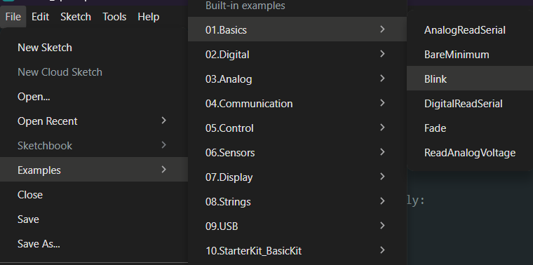
The Arduino IDE provides built-in examples that help you understand how the RP2040 board works. One of the simplest examples is the Blink program.
To open it, go to: File → Examples → 01.Basics → Blink
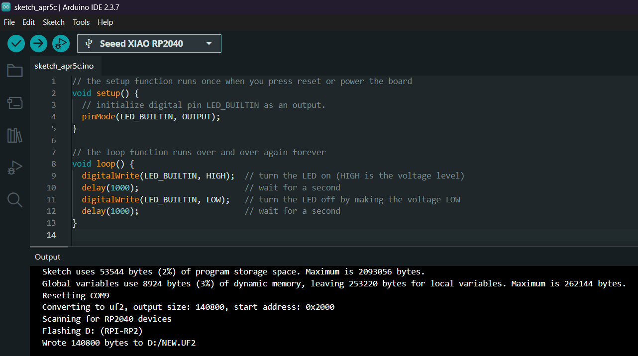
After opening it, you will see the following code:
// the setup function runs once when you press reset or power the board
void setup() {
  // initialize digital pin LED_BUILTIN as an output
  pinMode(LED_BUILTIN, OUTPUT);
}

// the loop function runs over and over again forever
void loop() {
  digitalWrite(LED_BUILTIN, HIGH); // turn the LED on
  delay(1000);                     // wait for a second
  digitalWrite(LED_BUILTIN, LOW);  // turn the LED off
  delay(1000);                     // wait for a second
}
The Arduino IDE includes a Verify function that checks your code for errors.
For example, if you remove a semicolon ;, the IDE will show where the error is so you can fix it.
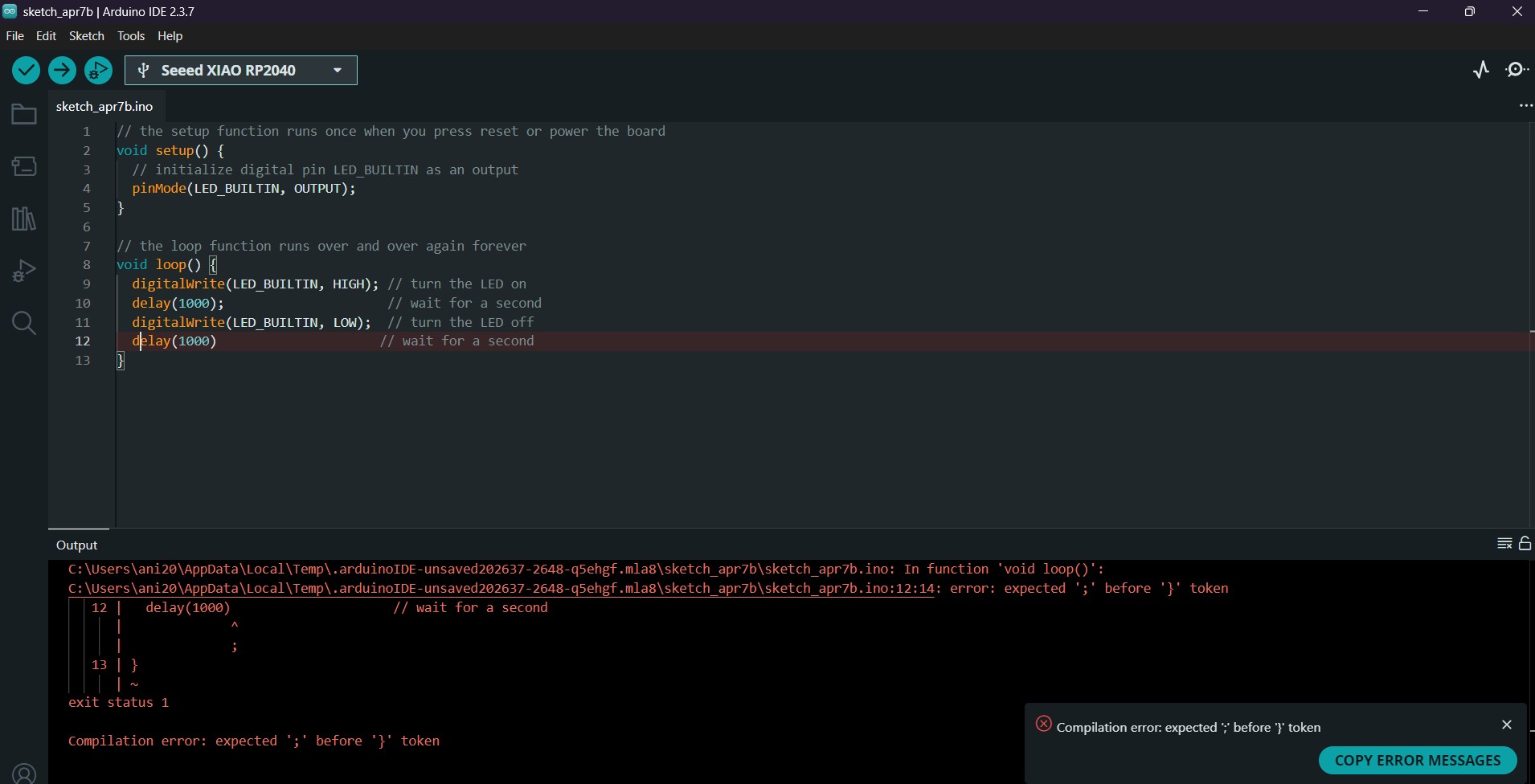
If there are no errors, Verify will also display:
- how much memory your program uses
- how much memory is available
Next, connect your RP2040 board (e.g., Raspberry Pi Pico) to your computer using a USB cable.
If you get an error during upload, it is usually because the correct port is not selected.
Go to: Tools → Port → select the correct port
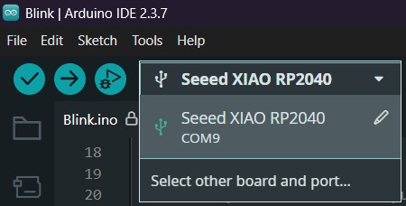
After selecting the port, click Upload to transfer the program to the board.
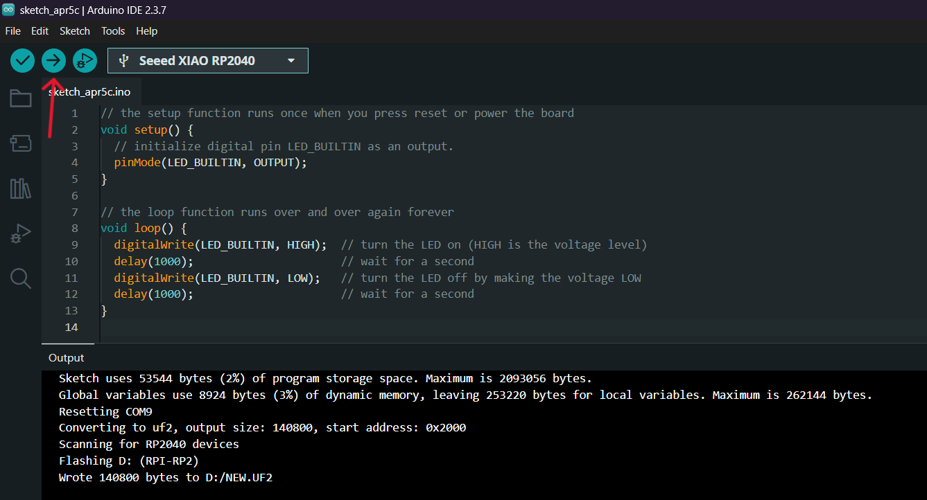
Once the program is successfully uploaded, the built-in LED on the RP2040 will start blinking:
- ON for 1 second
- OFF for 1 second
RGB LED Fade In / Fade Out Test
As a continuation of my experiments, I implemented a more dynamic lighting behavior by creating a fade-in and fade-out effect using the onboard RGB LED of the Seeed Studio XIAO RP2040.
In this test, instead of simply turning the LED on and off or switching between colors, I programmed the LED to gradually increase and decrease its brightness. This created a smooth transition effect, often referred to as a “breathing” light.
To achieve this, I used a loop to control the intensity of the red color channel, varying its value from 0 (off) to 255 (maximum brightness), and then back from 255 to 0.
As in the previous examples, I first enabled the power pin and initialized the NeoPixel library in the setup() function.
In the loop() function, I implemented two for loops:
- one for gradually increasing brightness (fade-in)
- one for gradually decreasing brightness (fade-out)
Fade Control Code
Below is the code used to create the fade-in and fade-out effect:
#include <Adafruit_NeoPixel.h>

int Power = 11;
int PIN = 12;
#define NUMPIXELS 1

Adafruit_NeoPixel pixels(NUMPIXELS, PIN, NEO_GRB + NEO_KHZ800);

void setup() {
  pixels.begin();
  pinMode(Power, OUTPUT);
  digitalWrite(Power, HIGH);
}

void loop() {
  // Fade in Red
  for(int i = 0; i <= 255; i++) {
    pixels.setPixelColor(0, pixels.Color(i, 0, 0));
    pixels.show();
    delay(10); // controls the speed
  }

  delay(500);

  // Fade out Red
  for(int i = 255; i >= 0; i--) {
    pixels.setPixelColor(0, pixels.Color(i, 0, 0));
    pixels.show();
    delay(10);
  }

  delay(500);
}
After uploading the program, the onboard RGB LED displayed a smooth transition effect: the red light gradually increased in brightness, reached its maximum intensity, and then slowly dimmed back to off. This cycle repeated continuously.
Extending Analog Input (Potentiometer)
In this experiment, I extended the functionality of the Seeed Studio XIAO RP2040 microcontroller by adding an analog input using a potentiometer.
Circuit Connection
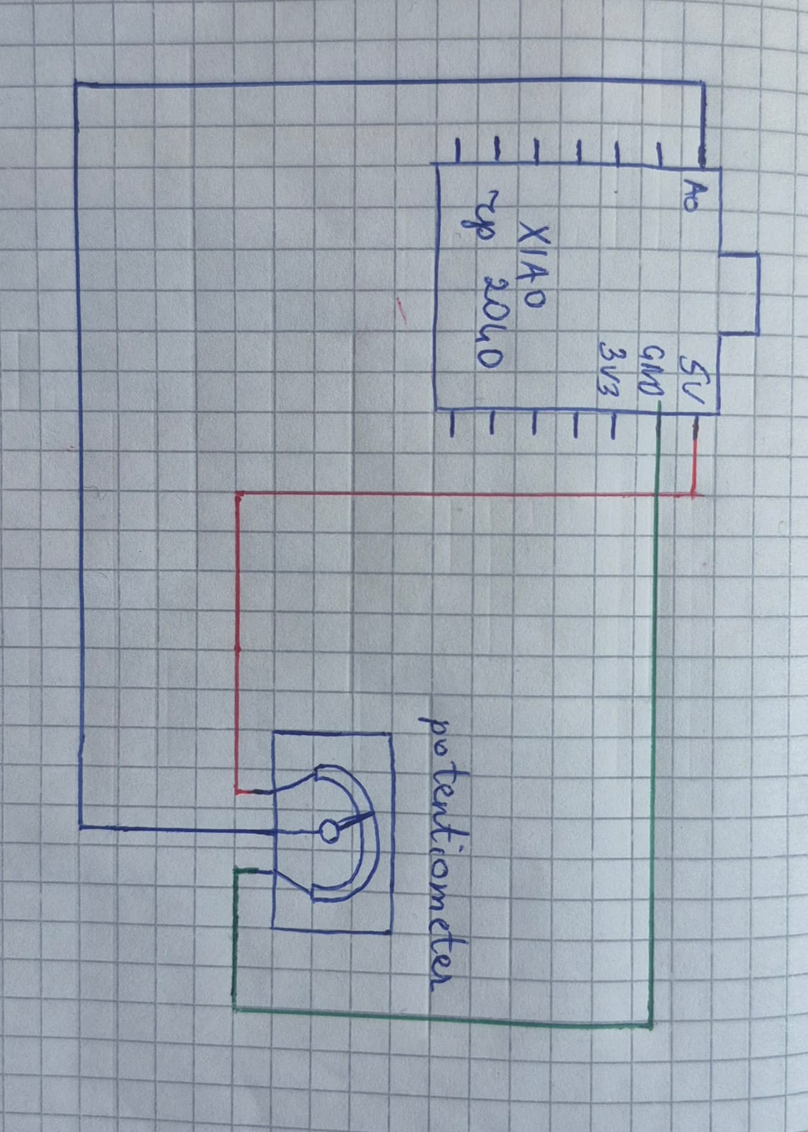
The potentiometer was connected as a voltage divider in the following way:
One end → 3.3V Other end → GND Middle pin (wiper) → A0 (Analog input)
With this setup, rotating the potentiometer changes the voltage at the A0 pin from 0V to 3.3V.
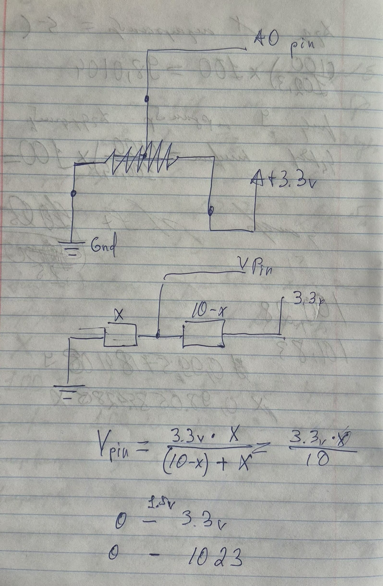
Voltage Divider Explanation
The potentiometer works as a voltage divider. It can be represented as two resistors connected in series, where the middle point (wiper) is connected to the A0 pin.
The voltage divider formula is:
$$ V_{out}=V_{in}\times\frac{R_2}{R_1+R_2} $$
In this case:
- The total resistance is constant (e.g., 10kΩ)
- One part is R₁ = X
- The other part is R₂ = 10 - X
- Input voltage is 3.3V
Therefore:
$$ V_{pin} = 3.3V \cdot \frac{10}{X} $$
This means that as the potentiometer is rotated, the ratio between the resistances changes, and the voltage at the A0 pin varies from 0V to 3.3V.
Components:
- 10k Potentiometer
Datasheet:
Reading Analog Values
I wrote a simple program in the Arduino IDE to read the value from pin A0 and display it in the Serial Monitor:
void setup() {
  Serial.begin(9600);
}

void loop() {
  int sensorValue = analogRead(A0);
  Serial.println(sensorValue);
  delay(100);
}
analogRead(A0)→ reads the input voltageSerial.println()→ prints the value
ADC (Analog to Digital Conversion)
The RP2040 microcontroller converts the analog voltage into a digital value using an ADC.
In the Arduino environment (10-bit resolution):
- 0V → 0
- 3.3V → 1023
So:
- Voltage range: 0 – 3.3V
- Digital range: 0 – 1023
While rotating the potentiometer:
- The values change smoothly
- The Serial Monitor displays values from 0 to 1023
This confirms that the analog input is working correctly.
Interfacing DHT11 with Seeed Studio XIAO RP2040
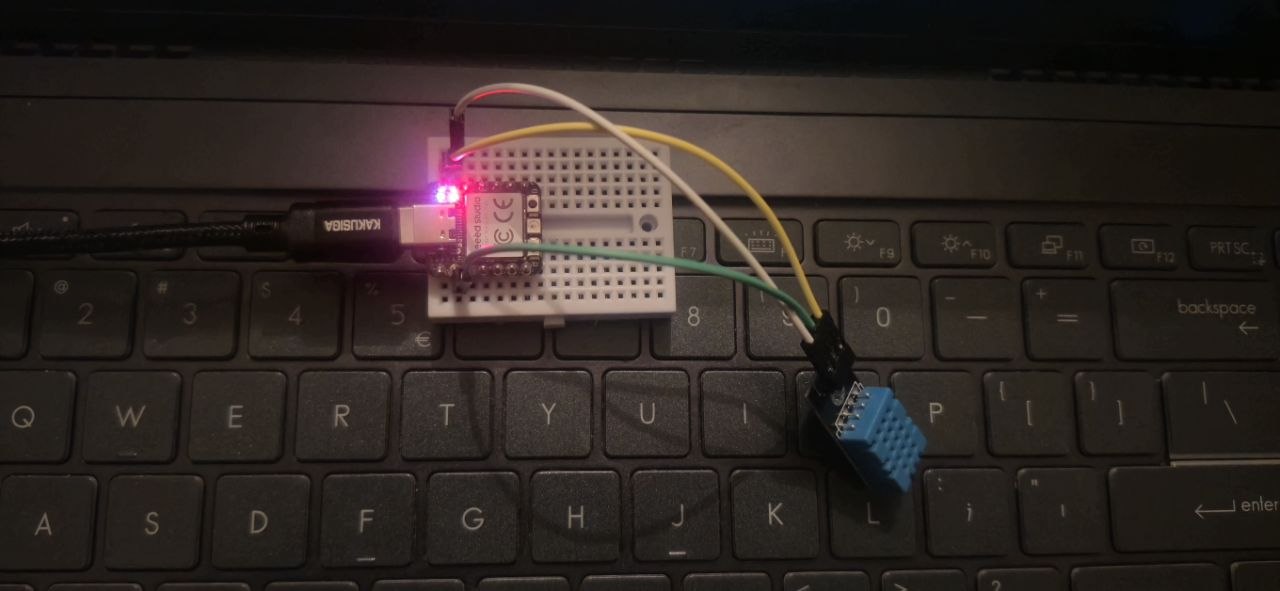
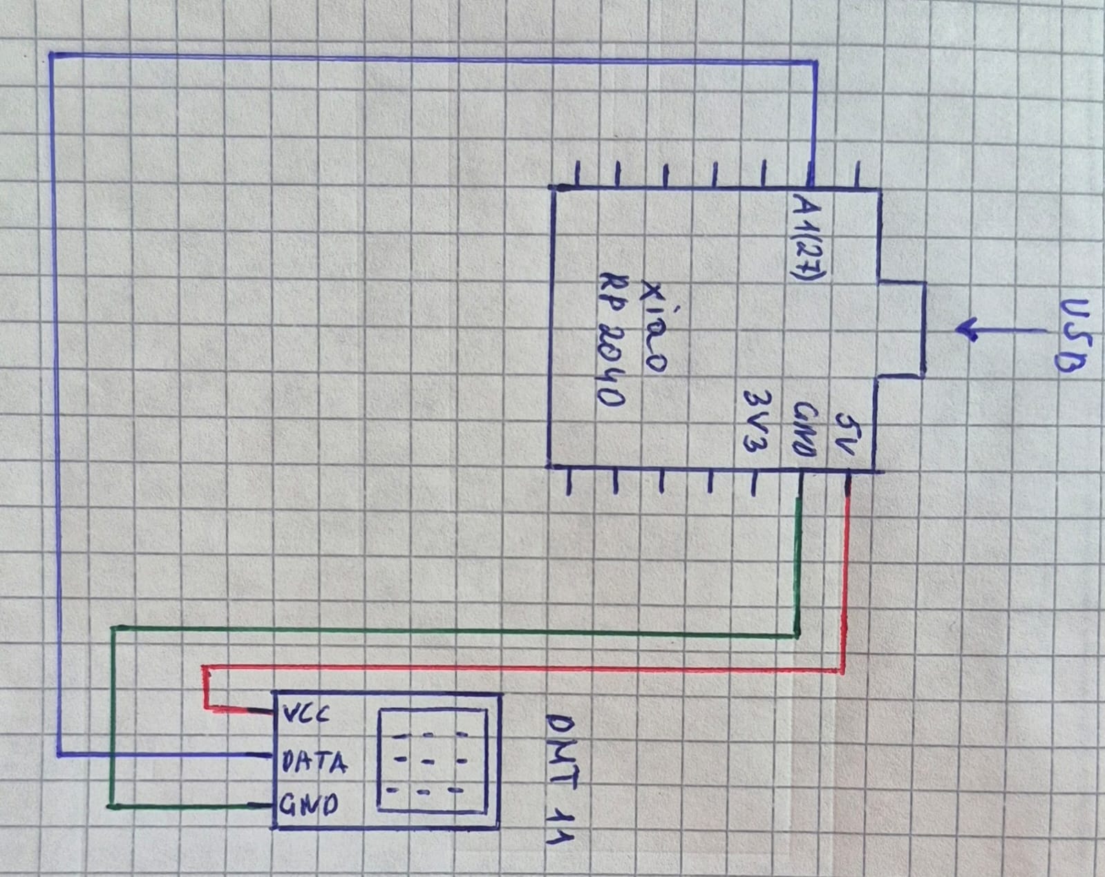
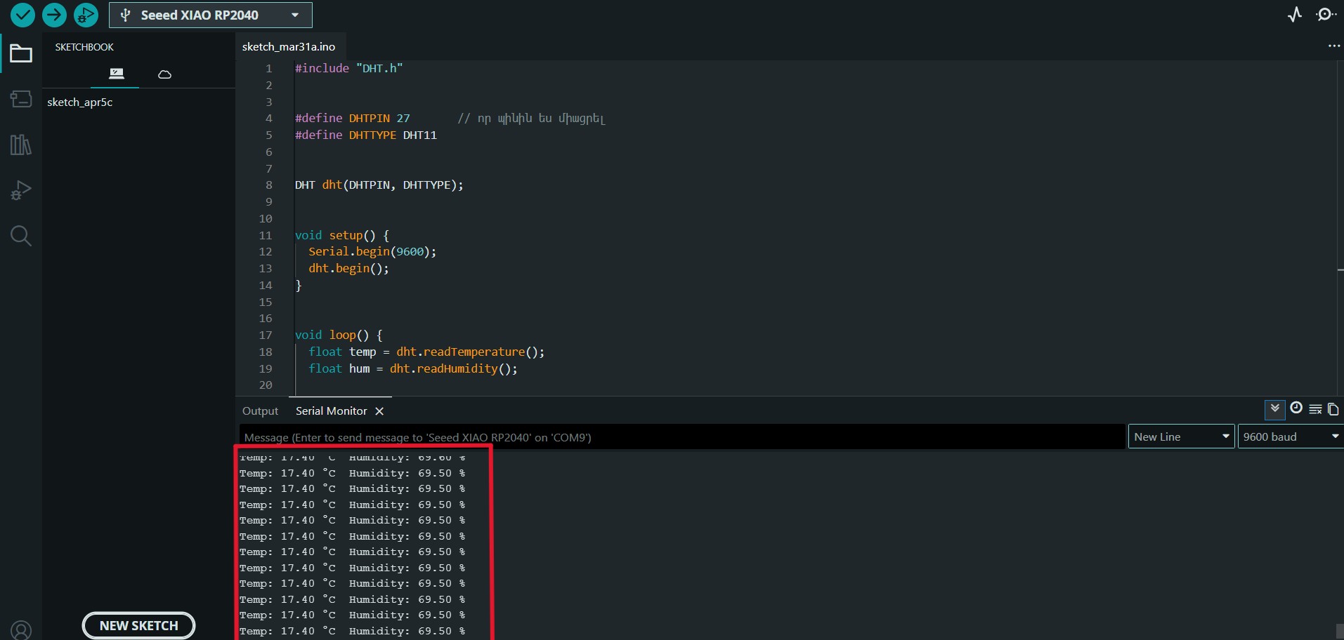
I conducted an experiment using the DHT11 sensor to measure environmental temperature and humidity. The sensor was connected to the Seeed Studio XIAO RP2040 microcontroller. During the setup, I ensured proper power supply to the sensor and correctly connected the data pin to the appropriate pin of the microcontroller.
For programming, I used suitable libraries that allow easy reading of the data transmitted by the sensor. During operation, the microcontroller periodically receives data from the sensor and converts it into readable values in terms of temperature (°C) and relative humidity (%).
The obtained data can be displayed on the serial monitor or used in other projects. As a result of this experiment, it was confirmed that the DHT11 sensor can effectively work with the Seeed Studio XIAO RP2040 microcontroller and provide the required measurements.
#include "DHT.h"   // including the DHT Library

// DHT11 configuration
#define DHTPIN 27
#define DHTTYPE DHT11
DHT dht(DHTPIN, DHTTYPE);

void setup() {

// starting serial at baud 9600
  Serial.begin(9600);

 // initializing sensor
  dht.begin();
}

void loop() {

// reading temperature value
  float temp = dht.readTemperature();

// reading humidity value
  float hum = dht.readHumidity();

// checking sensor data
  if (isnan(temp) || isnan(hum)) {
    Serial.println("Error reading sensor");
    return;
  }

// printing temperature value
  Serial.print("Temp: ");
  Serial.print(temp);
  Serial.print(" °C  ");

// printing humidity value
  Serial.print("Humidity: ");
  Serial.print(hum);
  Serial.println(" %");

// waiting 2 seconds
  delay(2000);
}
Write an Arduino code for Seeed Studio XIAO RP2040 using a DHT11 sensor. The code should use appropriate sensor-specific libraries, read temperature and humidity from GPIO 27, check for invalid readings, and print the results to the Serial Monitor in °C and %. The data should update every 2 seconds.
In the software part, I first downloaded and installed the DHT sensor library for Arduino. I then used the DHT.h library to read data from the DHT11 sensor.
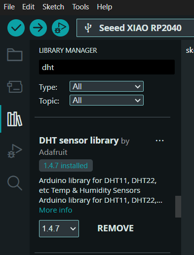
Next, I defined the sensor pin and initialized it to work with the Seeed Studio XIAO RP2040 microcontroller.
In the main loop, the temperature and humidity values are read, and if the data is valid, they are displayed on the serial monitor. The program runs periodically, obtaining new data every 2 seconds.
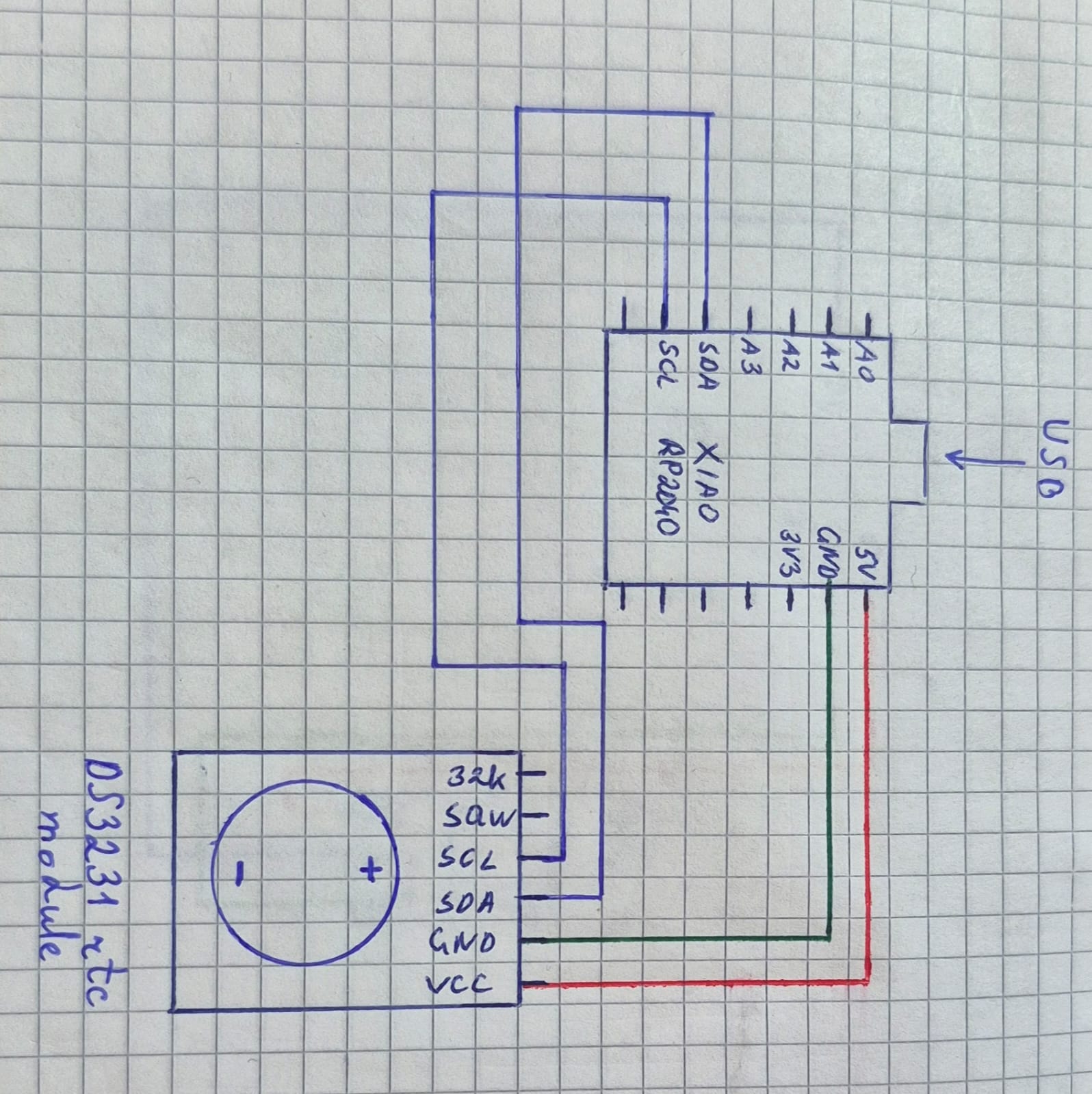
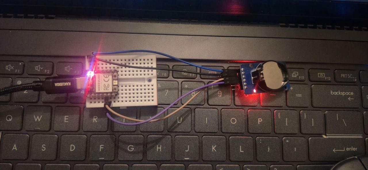
Communication (DS3231 – I2C Real-Time Clock)
In this experiment, I implemented real hardware communication using the DS3231 Real-Time Clock (RTC) module with the Seeed Studio XIAO RP2040 microcontroller.
Components:
- DS3231 rtc module
Datasheet:
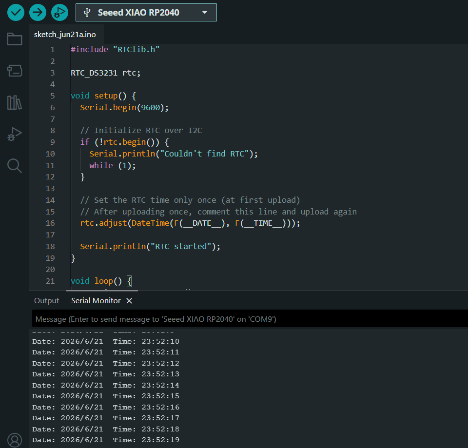
#include "RTClib.h"   // including the RTC library

RTC_DS3231 rtc;   // creating RTC object

void setup() {

// starting serial at baud 9600
  Serial.begin(9600);

  // initializing RTC module
  if (!rtc.begin()) {
    Serial.println("Couldn't find RTC");
    while (1);
  }

  // setting RTC time
  rtc.adjust(DateTime(F(__DATE__), F(__TIME__)));

  // printing status message
  Serial.println("RTC started");
}

void loop() {

// reading current date and time
  DateTime now = rtc.now();

// printing date
  Serial.print("Date: ");
  Serial.print(now.year());
  Serial.print("/");
  Serial.print(now.month());
  Serial.print("/");
  Serial.print(now.day());

// printing time
  Serial.print("  Time: ");
  Serial.print(now.hour());
  Serial.print(":");
  Serial.print(now.minute());
  Serial.print(":");
  Serial.println(now.second());

// waiting 1 second
  delay(1000);
}
Write an Arduino code for Seeed Studio XIAO RP2040 that works with a DS3231 RTC module. The code should use I2C communication and appropriate sensor-specific libraries. It should set the time once using compile time, then in the loop read the current date and time and print year, month, day, hour, minute, and second to the Serial Monitor. The data should update every 1 second.
The DS3231 module communicates with the microcontroller using the I2C communication protocol, which uses the SDA (data) and SCL (clock) lines. In this setup, the microcontroller acts as the master device, while the RTC module acts as the slave device.
Through this communication, the microcontroller continuously receives real-time data such as date and time (hours, minutes, and seconds) from the DS3231 module.
The received data is then sent to the computer via USB serial connection and displayed in the Arduino Serial Monitor for monitoring purposes. This output is used only for visualization and debugging, while the actual communication between devices happens through the I2C protocol.
This experiment demonstrates a true device-to-device communication system, where data is transferred between two hardware components using a standard embedded communication protocol (I2C), rather than only printing values from internal sensors.
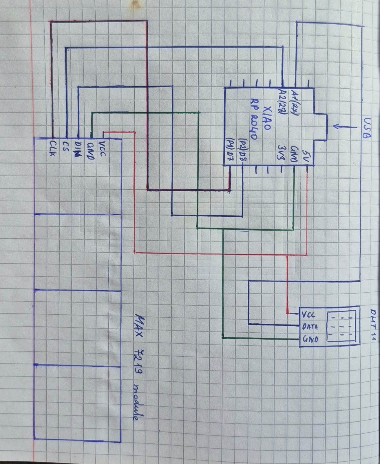
Communication (DHT11 + MAX7219)
Components:
- MAX7219
- DHT11
Datasheets:
In this experiment, embedded system communication was implemented using a DHT11 sensor, the Seeed Studio XIAO RP2040 microcontroller, and the MAX7219 LED driver module.
The DHT11 sensor provides temperature and humidity data, which is read by the microcontroller. This data is processed and then transmitted to the MAX7219 module for visual display.
#include <MD_Parola.h>     // including Parola library for display effects
#include <MD_MAX72XX.h>    // including MAX72XX library
#include <SPI.h>           // including SPI communication library
#include <DHT.h>           // including DHT library

#define HARDWARE_TYPE MD_MAX72XX::FC16_HW   // defining display hardware type

#define DATA_PIN 2    // display data pin
#define CLK_PIN  1    // display clock pin
#define CS_PIN   28   // display chip select pin

#define MAX_DEVICES 4   // number of LED matrix modules

#define DHTPIN 27       // DHT sensor pin
#define DHTTYPE DHT11   // sensor type

MD_Parola display(HARDWARE_TYPE, DATA_PIN, CLK_PIN, CS_PIN, MAX_DEVICES);   // creating display object
DHT dht(DHTPIN, DHTTYPE);   // creating sensor object

char msg[32];   // message buffer

bool showTemp = true;   // variable for switching between temperature and humidity

void setup() {

// starting serial at baud 115200
  Serial.begin(115200);

// initializing sensor
  dht.begin();

// initializing display
  display.begin();
  display.setIntensity(0);
  display.displayClear();
}

void loop() {

// reading temperature and humidity values
  float t = dht.readTemperature();
  float h = dht.readHumidity();

// checking sensor data
  if (isnan(t) || isnan(h)) {
    strcpy(msg, "DHT ERROR");
  } else {

// selecting what to display
    if (showTemp) {
      sprintf(msg, "TEMP %d C", (int)t);
    } else {
      sprintf(msg, "HUM %d %%", (int)h);
    }
  }

// showing text on display
  display.displayText(
    msg,
    PA_CENTER,
    0,
    5000,
    PA_SCROLL_DOWN,
    PA_SCROLL_DOWN
  );

// animating display
  while (!display.displayAnimate()) {

  }

// switching display mode
  showTemp = !showTemp;

// waiting before next update
  delay(200);
}
Write an Arduino code for Seeed Studio XIAO RP2040 that connects a DHT11 sensor and a MAX7219 LED matrix display. The code should use appropriate libraries for both the sensor and the display, read temperature and humidity, alternate between showing TEMP and HUM values on a 4-module display, use scrolling animation, update every 5 seconds, and display "DHT ERROR" in case of sensor failure.
The MAX7219 operates using an SPI-like serial communication protocol, which uses three main lines: Data (DIN), Clock (CLK), and Chip Select (CS). Through this communication, the microcontroller sends data to the LED driver, which converts it into a visible output on the LED matrix.
#include <MD_Parola.h>     // including Parola library for display effects
#include <MD_MAX72XX.h>    // including MAX72XX library
#include <SPI.h>           // including SPI communication library
#include <DHT.h>           // including DHT library

#define HARDWARE_TYPE MD_MAX72XX::FC16_HW   // defining display hardware type

#define DATA_PIN 2    // display data pin
#define CLK_PIN  1    // display clock pin
#define CS_PIN   28   // display chip select pin

#define MAX_DEVICES 4   // number of LED matrix modules

#define DHTPIN 27       // DHT sensor pin
#define DHTTYPE DHT11   // sensor type

MD_Parola display(HARDWARE_TYPE, DATA_PIN, CLK_PIN, CS_PIN, MAX_DEVICES);   // creating display object
DHT dht(DHTPIN, DHTTYPE);   // creating sensor object

char msg[32];   // message buffer

unsigned long lastSwitch = 0;   // storing last switch time
bool showTemp = true;           // switching between temperature and humidity

void setup() {

// starting serial at baud 115200
  Serial.begin(115200);

// initializing sensor
  dht.begin();

// initializing display
  display.begin();
  display.setIntensity(0);
  display.displayClear();
}

void loop() {

// running display animation continuously
  display.displayAnimate();

// checking if 5 seconds passed
  if (millis() - lastSwitch > 5000) {
    lastSwitch = millis();

// reading temperature and humidity values
    float t = dht.readTemperature();
    float h = dht.readHumidity();

// checking sensor data
    if (isnan(t) || isnan(h)) {
      strcpy(msg, "DHT ERROR");
    } else {

// selecting message to display
      if (showTemp) {
        sprintf(msg, "TEMP +%dC", (int)t);
      } else {
        sprintf(msg, "HUM %d%%", (int)h);
      }
    }

// switching display mode
    showTemp = !showTemp;

// showing text on display
    display.displayText(
      msg,
      PA_LEFT,
      80,
      0,
      PA_SCROLL_LEFT,
      PA_SCROLL_LEFT
    );
  }
}
Write an Arduino code for Seeed Studio XIAO RP2040 using a DHT11 sensor and a MAX7219 LED matrix display. The code should use appropriate sensor and display libraries, implement non-blocking logic without delay(), use millis() for timing, read DHT11 data from GPIO 27, switch between temperature and humidity display every 5 seconds, show scrolling text on the display, and show "DHT ERROR" in case of errors.
Thus, the system demonstrates a real device-to-device communication flow, where:
- The DHT11 acts as the data source (sensor input)
- The RP2040 acts as the processing unit
- The MAX7219 acts as the output device
- Data transmission is carried out using a serial SPI-like protocol
During the experiments with the MAX7219 module, different display behaviors were observed. In one case, the text was displayed in a right-to-left scrolling direction, where the content moved horizontally across the screen. In another case, the same or similar text was presented in a top-to-bottom movement format, where the information flowed vertically on the display.
These two different display methods demonstrate how the presentation of output data can be controlled through programming and how its visual behavior can be modified. Changing the direction of the display allows the creation of different visual effects and can make the information more understandable or more visually emphasized.
Overall, this experiment demonstrates a complete embedded system data flow, from sensor input to hardware output, using a standard communication protocol.
Code Sources and Experimentation
During this week, most of the code used in the experiments was created with the assistance of ChatGPT (OpenAI) as a learning and programming support tool. Since this topic was completely new for me at the beginning, and I did not fully understand embedded programming and communication protocols, AI played an important role in my learning process.
ChatGPT was used to generate initial code examples, understand their logic, and adapt them to the Seeed Studio XIAO RP2040 board and the different components used in the project.
In addition to AI assistance, I also used the following sources:
- Arduino IDE built-in examples
- Library examples (DHT.h, Adafruit NeoPixel, RTClib, MD_MAX72XX / MD_Parola)
- Seeed Studio XIAO RP2040 official documentation and wiki page
ChatGPT was used for:
- generating basic code structures for sensors and modules
- understanding communication protocols such as I2C and SPI-like communication
- debugging errors and adjusting pin configurations
- modifying delays, reading intervals, and display behavior
The code was then tested and modified through practical experiments. Since the topic was new for me, each modification and test helped me better understand how embedded systems work in real hardware.
Overall, this process was mainly a learning phase, where AI served as a guide, and hands-on experimentation helped me develop a deeper understanding of the system.
Conclusion
During this week, I gained practical experience in embedded systems development using the Seeed Studio XIAO RP2040 microcontroller. I worked with the Arduino IDE to write, upload, and test different programs, and explored both digital and analog input/output operations.
Throughout the experiments, I implemented and documented real hardware interactions using sensors and output devices, including the DHT11 sensor, a potentiometer, an RGB LED, the DS3231 real-time clock module, and the MAX7219 LED driver. I also applied different communication protocols such as I2C and SPI-like serial communication to enable data exchange between the microcontroller and external modules.
These activities helped me understand not only how sensors and actuators work individually, but also how embedded systems operate as complete data flow systems—from input acquisition, to processing, and finally to visual or functional output.
Overall, this week strengthened my understanding of embedded programming and hardware communication, and improved my ability to design and implement interactive electronic systems.