Week 16. Wildcard Week
The main goal of this week’s assignment was to design and manufacture a new product using a digital fabrication process that had not been included in previous assignments, as well as to document the entire process by providing all the necessary information required for its reproduction.
As such, we had already worked with the laser cutting process during Week 3; however, this time we applied a different technology — an industrial fiber laser, which is specifically designed for metal processing.
During Week 3, the laser cutting process was mainly applied to non-metallic materials, whereas in this project, the work was carried out using a more powerful and precise fiber laser designed for cutting and processing metal sheets. This difference also affected the working parameters, including laser power, cutting speed, focus settings, and the use of assist gases.
In addition, the metal processing workflow required more detailed preparation, precise machine calibration, and strict adherence to safety requirements. Therefore, although laser cutting was used in both assignments, this week’s project differed from the previous one in terms of the technology used, the material processed, and the overall manufacturing process.
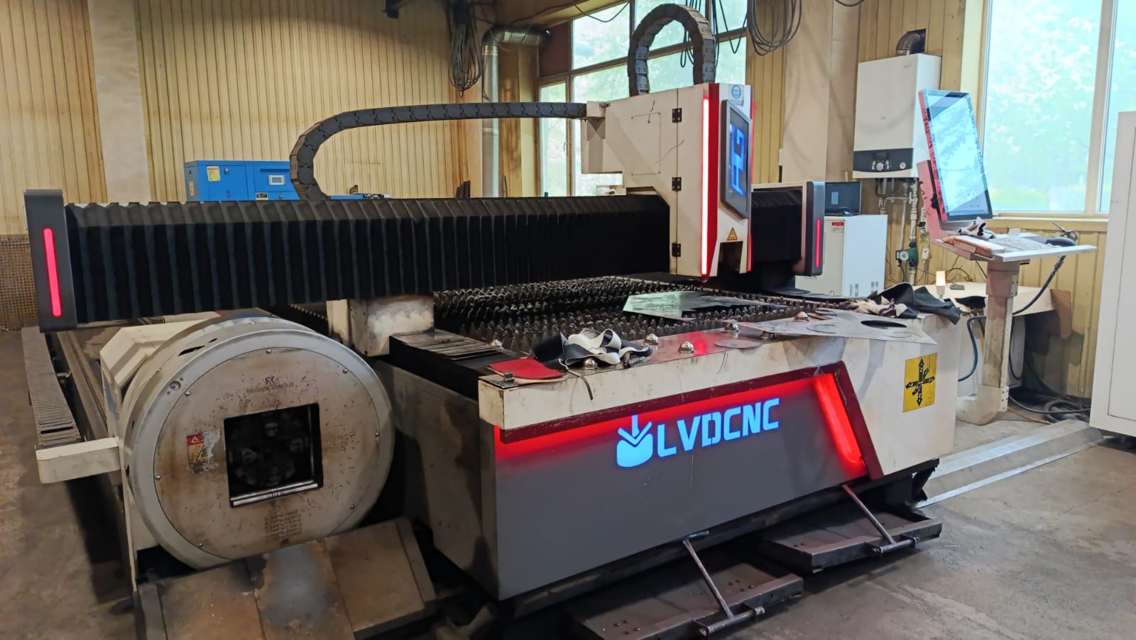
For this purpose, Gevorg and I visited a local workshop in our city where several types of metal fabrication machines were available. The process that interested us the most was Laser Cutting of Metal. During the visit, the operators introduced us to the structure of the laser cutting machine, its working principles, and the main safety procedures.
We had the opportunity to observe how the laser beam processes metal sheets with high precision and creates the required parts.
Machine Specifications
| Parameter | Value |
|---|---|
| Laser Type | Fiber Laser |
| Power | 6 kW (6000 W) |
| Model | 4015–6000W CNC Fiber Laser Cutting Machine |
| Manufacturer | LVDCNC |
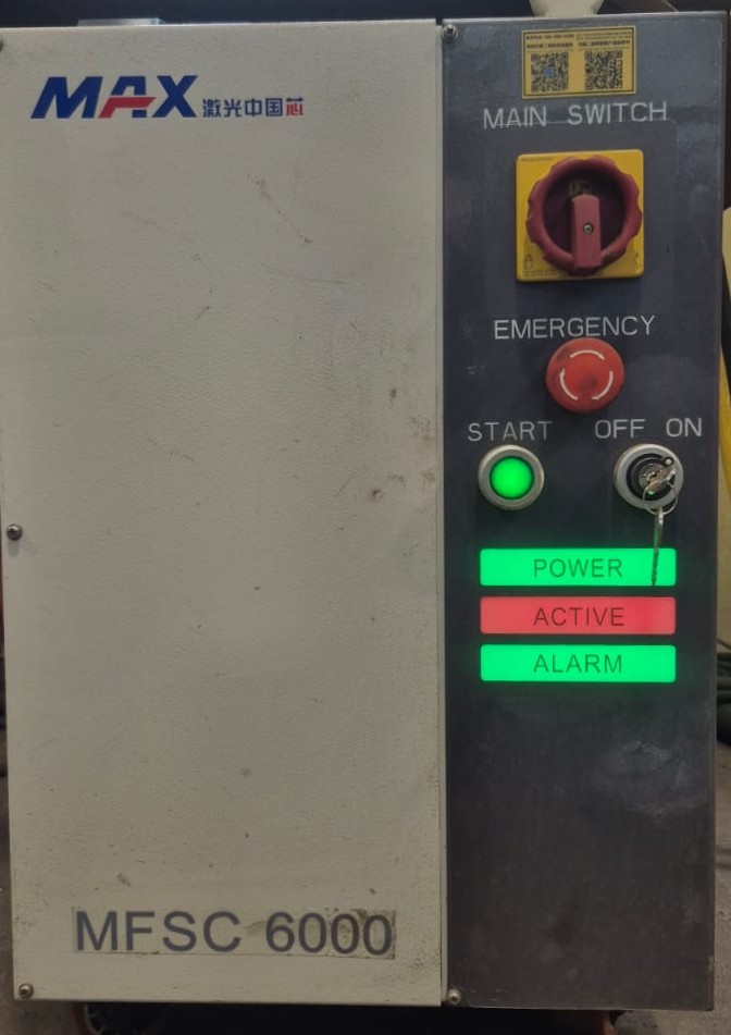
| Laser Source | MAX Photonics MFSC-6000 |
| Software | CNC Control Software |
| Supported File Formats | DXF, DWG, AI, and other vector-based CAD files |
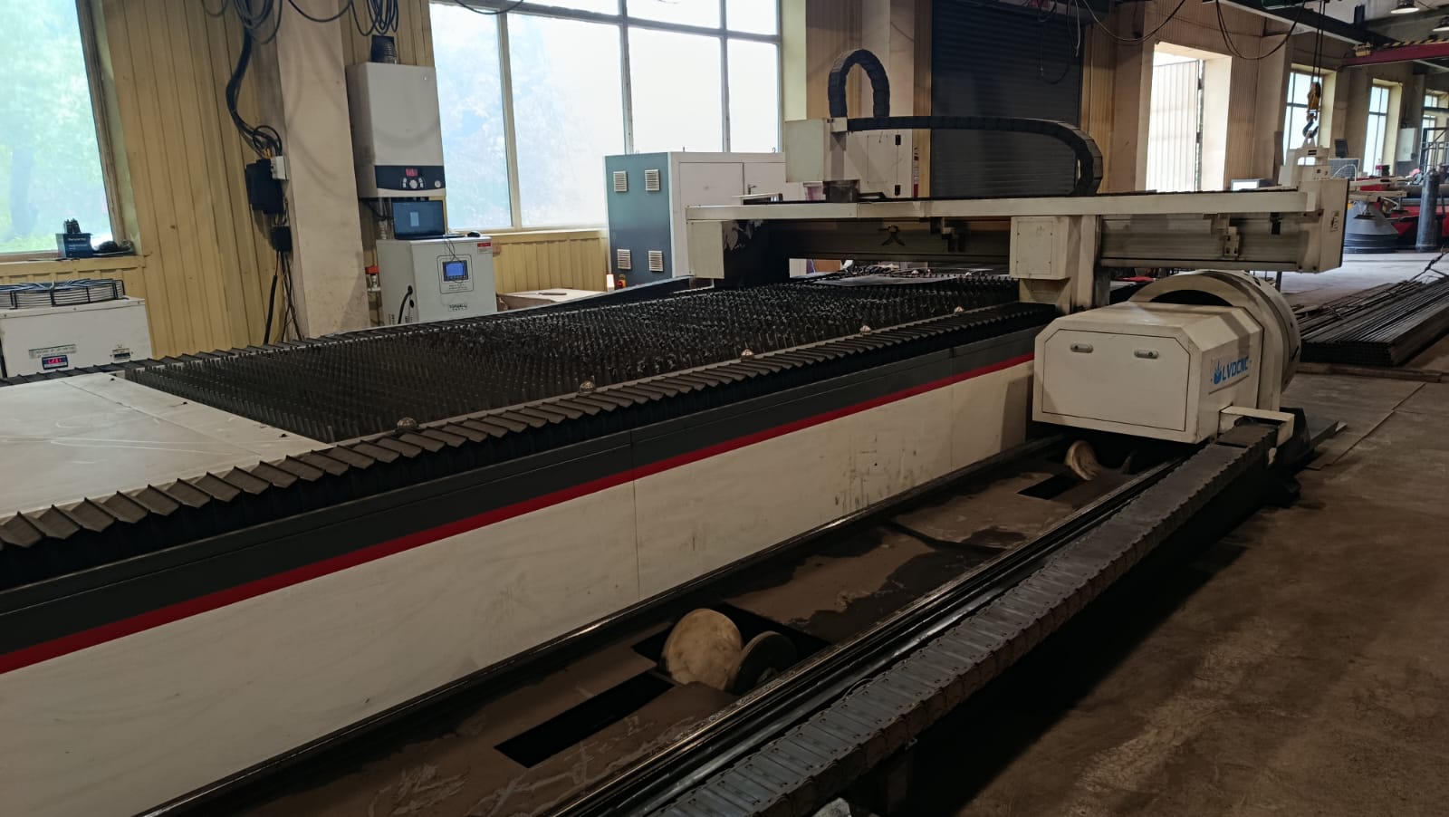
| Working Area | 4000 × 1500 mm |
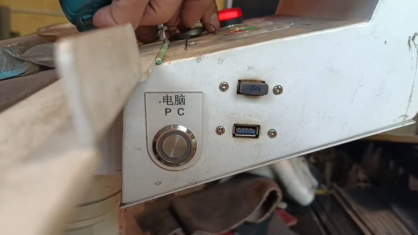
The machine used in the workshop was a high-power industrial laser system designed for precise cutting of metal sheets up to 2 cm thick. It had a separate control panel containing the power, control, and safety buttons.
We were also introduced to the Emergency Stop button, which is used to immediately stop the machine in emergency situations. In addition, the panel included Power, Active, and Alarm indicators showing the current state of the machine.
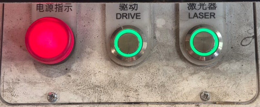
The panel also contained several important control buttons and indicators. The Drive button was used to activate the motion system responsible for moving the laser head. The Laser button activated the laser source and allowed the cutting process to begin. The red indicator on the left showed that the machine was powered on, while the illuminated green buttons indicated that the corresponding systems were active.
Control Panel
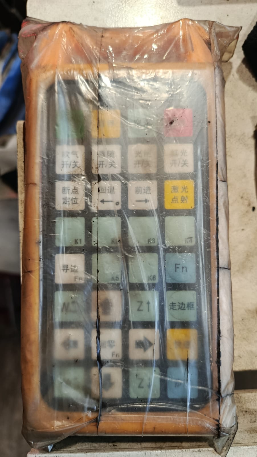
The machine also had a separate handheld control panel that allowed the operator to manually control the laser head and different machine functions.
The panel included directional buttons, laser activation controls, return functions, pause/start controls, and several other operational buttons.
This controller was especially useful during the calibration phase, when it was necessary to manually move the laser head, define the starting point, or check the cutting process. It allowed more accurate control over the workflow and made it easier to quickly react to necessary adjustments.
Nozzles and Gas Usage
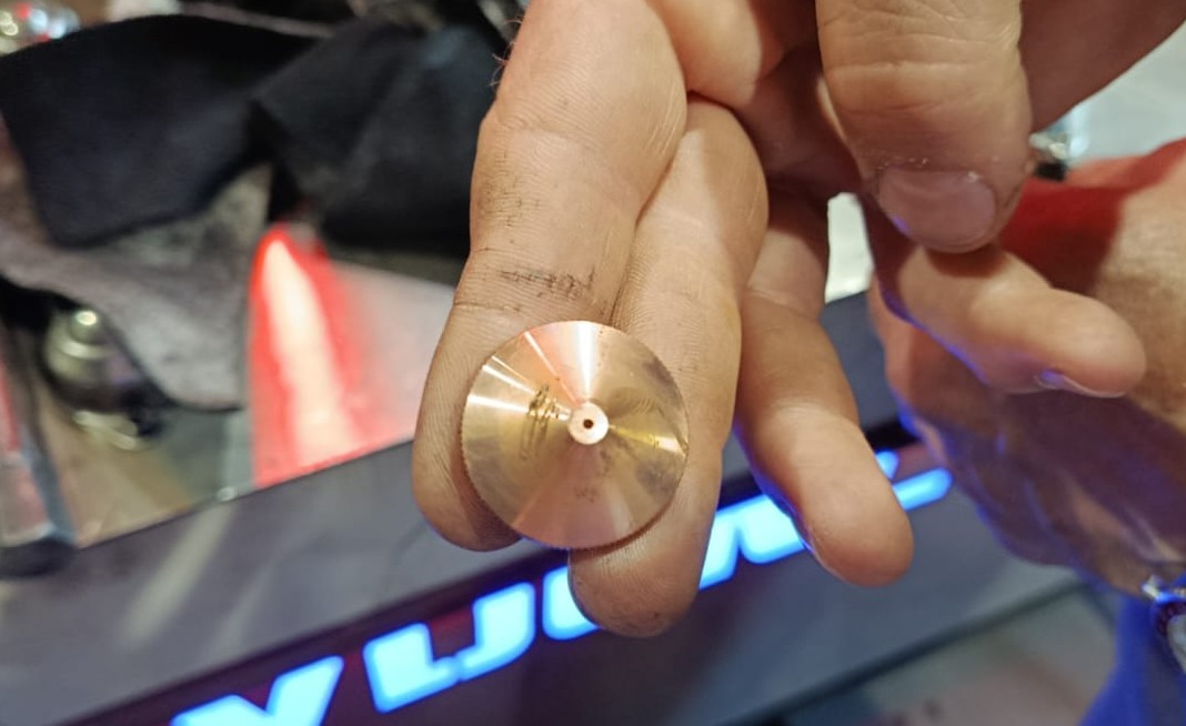
After learning about the machine controls, we also studied the laser nozzles, which play an important role in ensuring cutting precision and quality.
Different nozzle diameters were used depending on the thickness of the metal and the type of cut. In the workshop, we were told that 1.2 mm, 1.4 mm, 1.5 mm, and other nozzle sizes were commonly used. Smaller nozzles provide more precise and detailed cuts, while larger nozzles are better suited for thicker materials because they remove molten metal more efficiently from the cutting area.
Since we were cutting 1.2 mm thick metal, we used a 1.2 mm nozzle. Choosing the correct nozzle was very important because it directly affected the cutting precision, edge quality, and overall result. With this nozzle, we achieved clean and even cuts without unwanted deformation or material damage.
When cutting metal with a thickness of 3 mm or more, oxygen is commonly used to ensure cleaner cuts and prevent slag from remaining on the backside of the material. Oxygen increases the pressure, making it easier and more efficient for the laser beam to pass through the metal.
When the gas pressure is sufficiently high, the cut becomes smoother and cleaner. If the pressure is too low, the nozzle may become damaged, the cutting quality decreases, and slag or molten material may remain on the backside of the metal.
For metals thinner than 3 mm, compressed air or nitrogen is generally used because high pressure is not required. Thin metal is easier for the laser to penetrate, making it possible to achieve clean and precise cuts even under lower pressure conditions.
Using nitrogen or compressed air also results in cleaner edges with less oxidation. Additionally, the chance of damaging the nozzle is lower during thin metal cutting.
Safety Rules
During the machine demonstration, we were also introduced to the main safety rules that had to be followed while working with the laser cutter. Since the machine operates at high temperatures and contains high-speed moving systems, following safety procedures was essential both for proper workflow organization and for avoiding potential hazards.
- Wear protective safety glasses while staying in the working area.
- Do not stand near the moving rails, since they move at high speed.
- Do not touch moving machine parts during operation.
- Wait until the machine completely finishes its process before approaching the work area.
- Maintain a safe distance from the machine throughout the cutting process.
Material
For this project, I used a 1.2 mm thick carbon steel sheet.
- Material: Carbon Steel
- Type: Carbon Steel Sheet
- Thickness: 1.2 mm
Carbon steel sheet was selected because it provides good mechanical strength, can be cut accurately with a fiber laser, is easy to bend, and is suitable for welding. Although this assignment is not my final project, I plan to use the same material in my final project. Therefore, this week gave me the opportunity to become familiar with the material, its properties, and its behavior during the fiber laser cutting process.
For more information about carbon steel, see
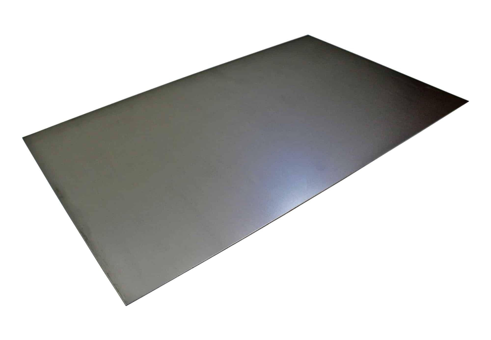
Image source: SMETALS – 1.2 mm Thick Mild Steel Sheet
Design Part
During this week, I was thinking about how I could apply the fabrication process explored in Wildcard Week to my final project. I decided to separate some elements from the upper part of my final project design and cut them from metal at a smaller scale.
After completing my final project, I plan to transform these elements into a separate product, either as a small desk lamp or a wall-mounted decorative light object. This idea would allow me to reuse the developed design in a new format and further explore the combination of metal and lighting in small-scale products.
I took the AI-generated image of my final project and gave it back to ChatGPT with the following prompt to generate the wall lamp concept I wanted.
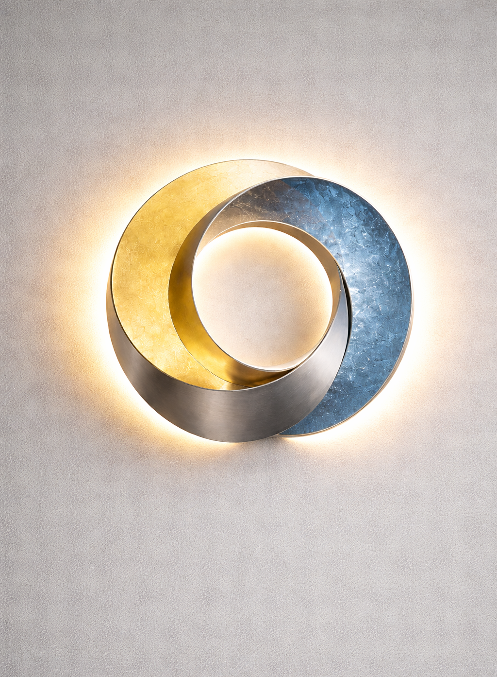
Transform the upper circular sculptural part into a compact modern wall lamp, removing the lower/base section completely. Keep the abstract intertwined ring design, make it realistic for wall mounting, around 15–20 cm in size, with soft warm ambient LED lighting and a minimal contemporary aesthetic․
Using the AI-generated concept as a reference, I recreated the design of the upper section of my final project in Adobe Illustrator and prepared the vector details required for fabrication. My goal was to preserve the flowing and intertwined forms of the original concept while adapting them to the requirements of the manufacturing process.
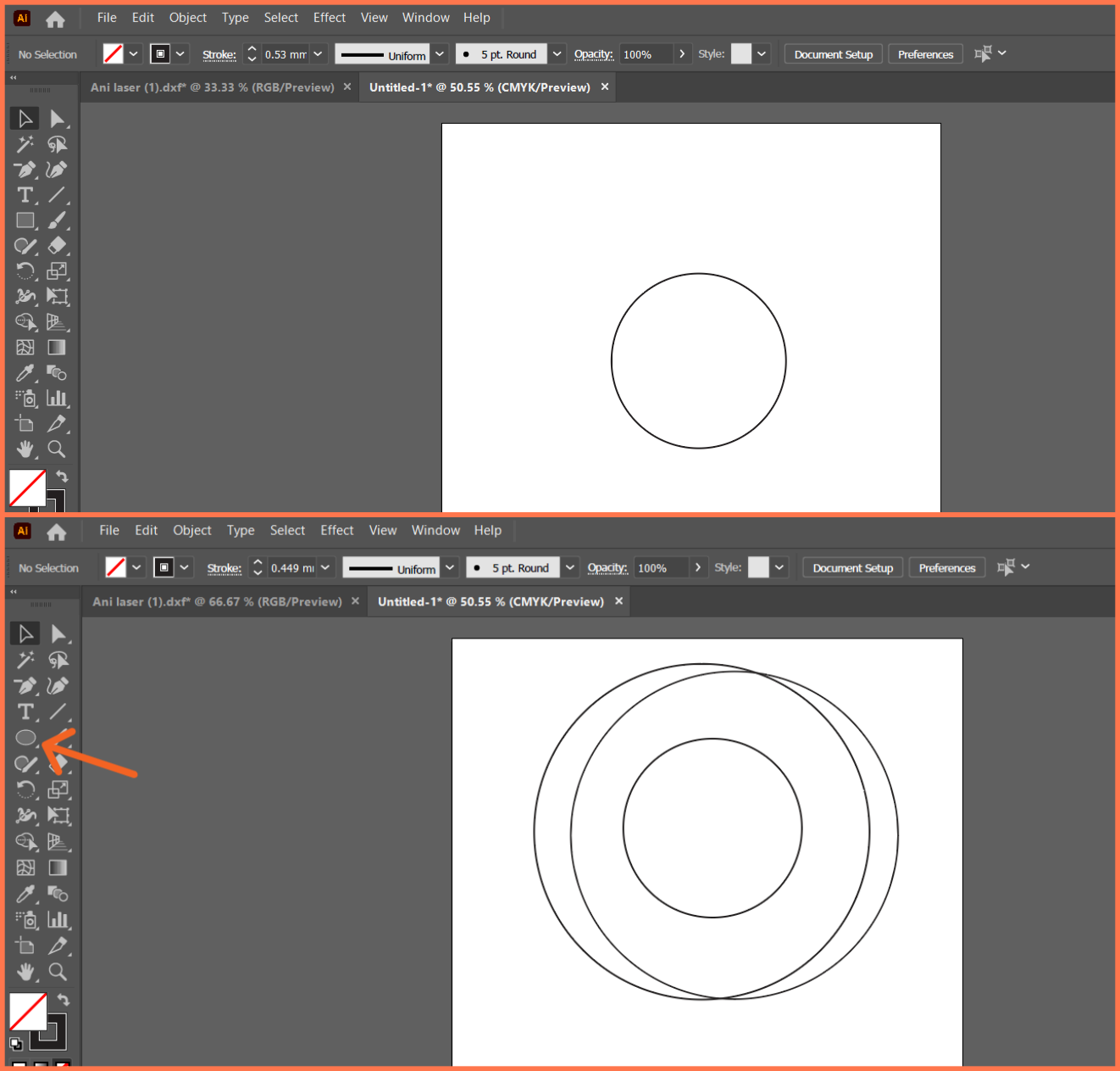
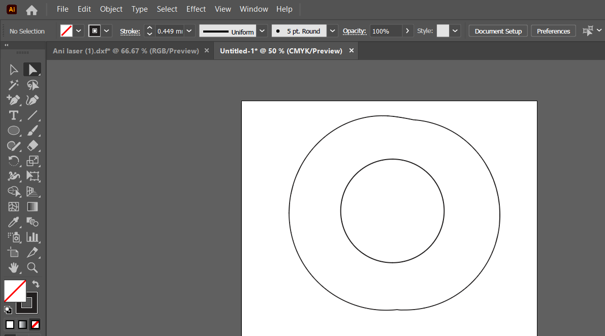
First, I drew the main circle with the Ellipse Tool, then created the circles that would form the outer contour.
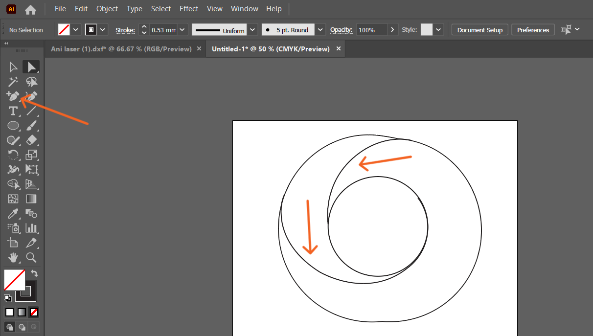
After that, in order to remove the unnecessary inner parts, I added new anchor points with the Pen Tool in the necessary places.

Then, I selected these points with the Direct Selection Tool and applied the Cut Path at Selected Anchor Points command, dividing the path into separate parts. Finally, I selected and deleted the unnecessary curved lines, obtaining the desired outer contour.
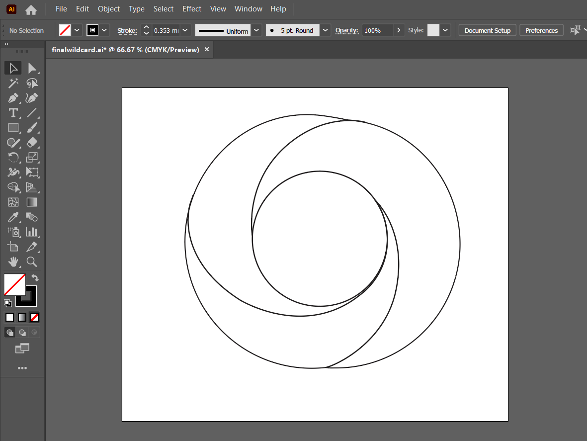
In the next step, I moved on to forming the inner lines. To do this, I used the Pen Tool, manually drawing smooth and continuous curves that connected the already existing circular elements.
Working gradually, I formed lines that harmonized with each other, which completed the composition and gave the object a more organic and flowing look. The result was a complete and harmonious linear design that combines the outer contour and the inner flowing curves, forming the final image and ensuring its aesthetic integrity.
CAM Process and Cutting
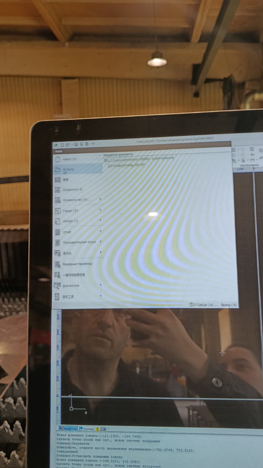
After completing the design in Adobe Illustrator, I exported it as a DXF file since it is one of the file formats supported by the fiber laser cutting machine.
The DXF file was transferred to the machine using a USB flash drive and then imported into the CNC control software.
After importing the file, its geometry was checked to ensure that all contours had been imported correctly.
Next, the cutting parameters were configured according to the selected material.
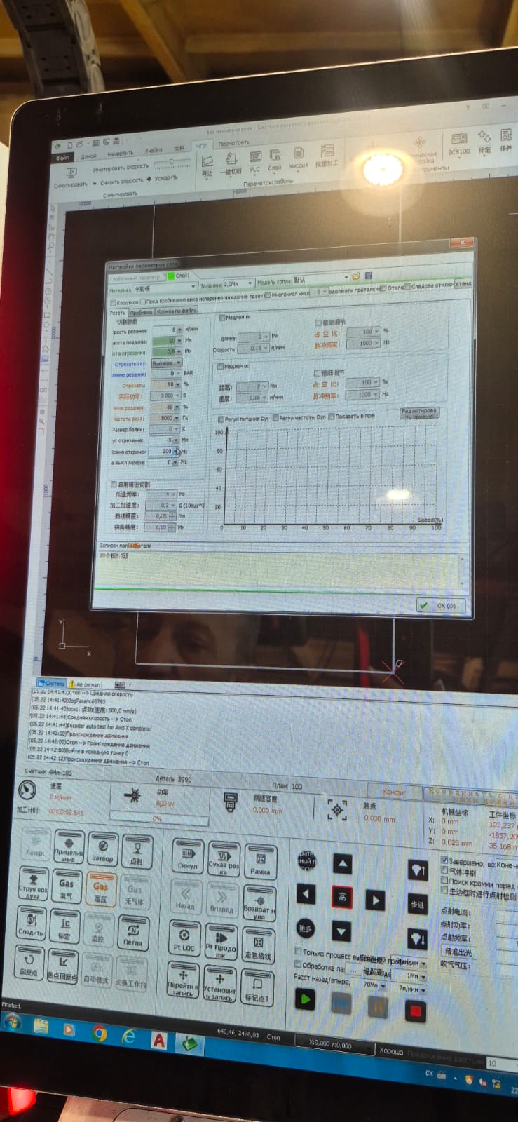
Since I used a 1.2 mm thick carbon steel sheet, the following parameters were applied:
| Parameter | Value |
|---|---|
| Laser Power | 3000 W |
| Feed Rate | 8 m/min |
| Assist Gas | Compressed Air |
| Gas Pressure | Approximately 8 bar |
| Frequency | 1000 Hz |
| Gap | 0.5 mm |
| Focus Offset | −5 mm |
These settings ensured a stable cutting process and produced clean, smooth edges without noticeable deformation or excessive slag.
The machine was then calibrated. The Z-axis was adjusted so that the laser head was positioned at the correct working distance from the metal surface.
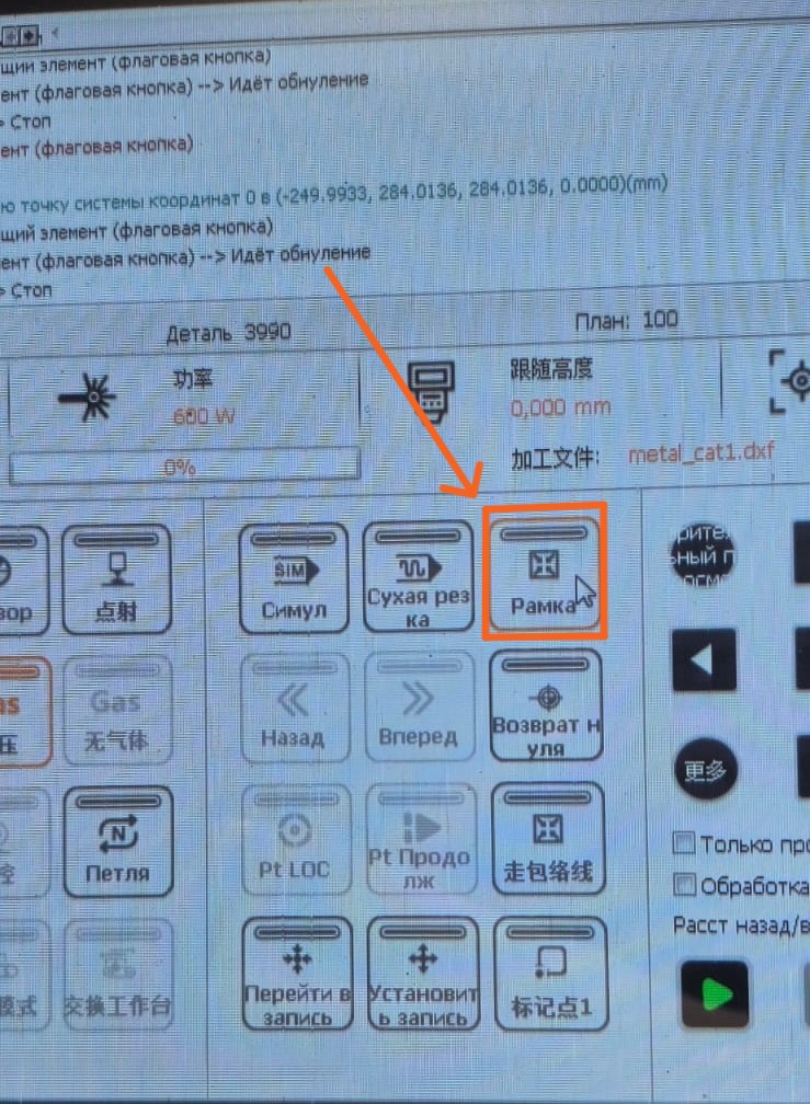
After calibration, the Frame function was used to verify that the design was correctly positioned on the metal sheet before starting the cutting process.
Once everything was properly configured, we started the cutting process. However, during the first attempt, we realized that the software was not displaying the cutting sequence correctly. The laser cut the outer contour first, causing the part to separate from the sheet before the internal features had been completed.
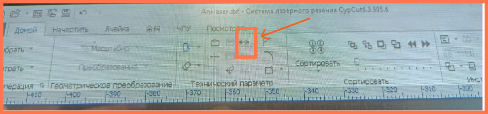
To solve this problem, we used the Bridge (Micro Joint/Tab) function, which leaves small uncut sections to keep the part attached to the sheet until the cutting process is completed.
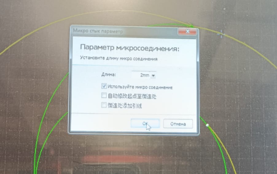
Setting the Micro Joint (Bridge) length to 2 mm.
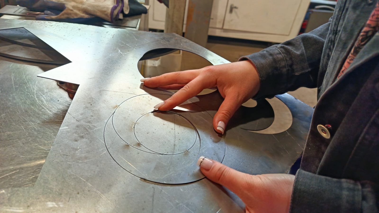
After adding several tabs, we started the cutting process again.
This time, the part remained securely attached throughout the entire process and could be easily removed after cutting.
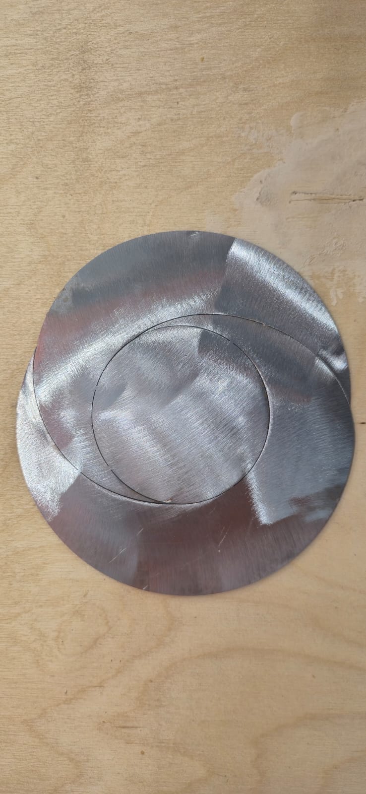
The final result was a clean and accurate metal part with smooth edges and no deformation.
Sanding
After the laser cutting process, I cleaned the front and bottom surfaces of the metal part using an INTERSKOL UShM-125/900 Angle Grinder.
The sanding was carried out because the metal had developed a light layer of surface rust during storage. I cleaned only the front and bottom surfaces to remove the rust and improve the appearance of the metal. The edges and shape of the part were not modified during the sanding process.
Conclusion
During this week, I was able to learn about the operation of an industrial fiber laser cutting machine and observe how metal laser processing is performed in real production conditions.
Although the available time was limited and we could not fully explore all the machine’s capabilities, the experience was still very useful and interesting.
Throughout the assignment, I was able to apply my own design, prepare the DXF file, and produce a real metal-cut component. In addition, this assignment helped me think about how I can apply this fabrication process in my final project and transform my design into a small metal lighting object.