Week 7. Computer-Controlled Machining
Group Assignment
In this week’s group assignment, together with Rudolf Igityan and Mkhitar Evoyan, we explored the basic principles of operating a CNC milling machine and learned about the tools and components used during the machining process.
We examined the machine interface, power controls, different types of milling bits used for cutting materials, as well as the safety rules that must be followed when working with CNC machines to prevent accidents and ensure the protection of both the operator and the equipment.
Understanding these components is important for operating the CNC machine safely and achieving accurate machining results.
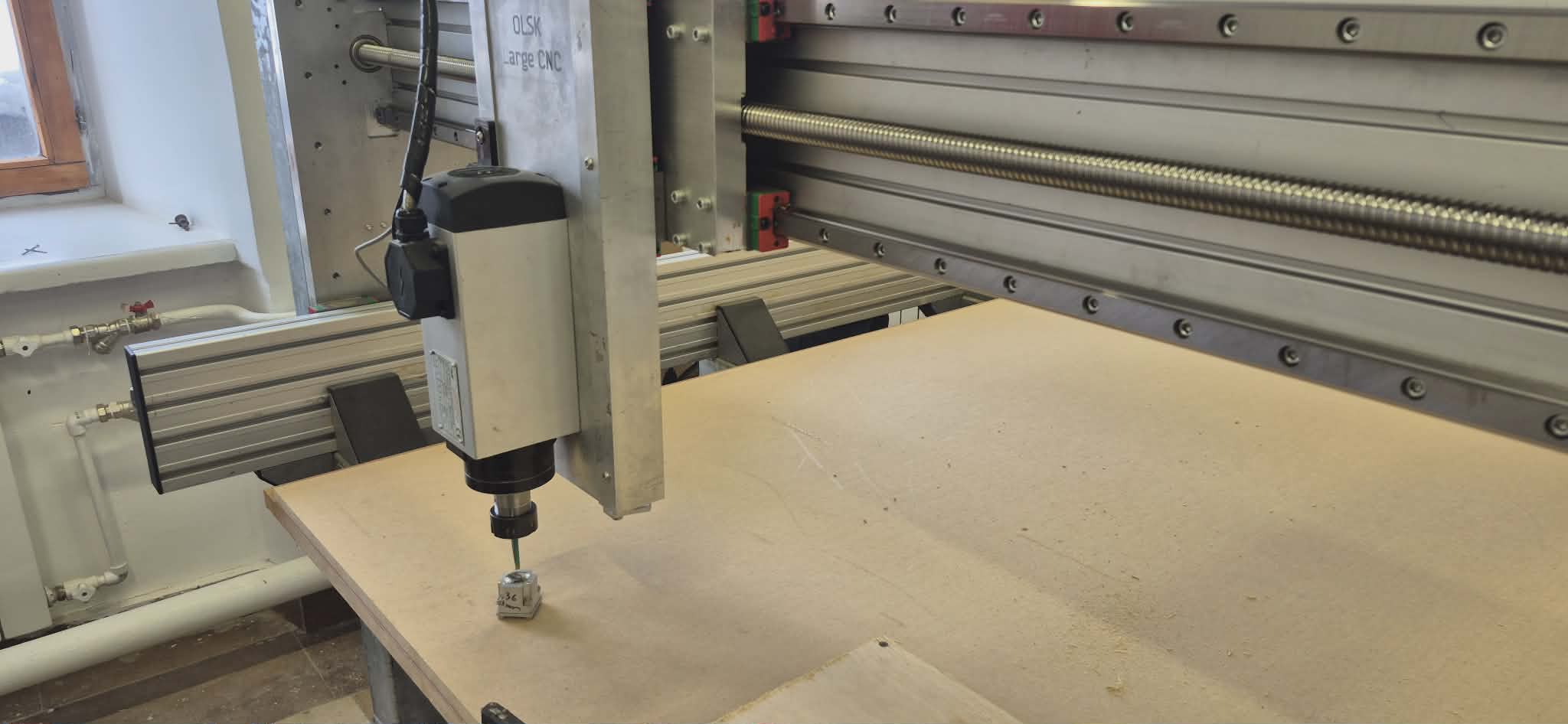
Technical Specifications of OLSK Large CNC V1
| Parameter | Description |
|---|---|
| Machine Name | OLSK Large CNC V1 |
| Machine Type | CNC Milling Machine |
| Milling Volume | 2500 × 1250 × 300 mm |
| Frame | Steel pipes combined with solid aluminum parts and aluminum profiles |
| Motion System | Ball Screw and Rack & Pinion |
| Guides | 25 mm Linear Rails |
| Motors | NEMA 34 Stepper Motors |
| Homing System | Inductive Sensors |
| Spindle Cooling | Air Cooling |
| Power Supply | 220 V |
| Axes | X, Y, Z |
| Application | Machining of wood, plastics, and other sheet materials |
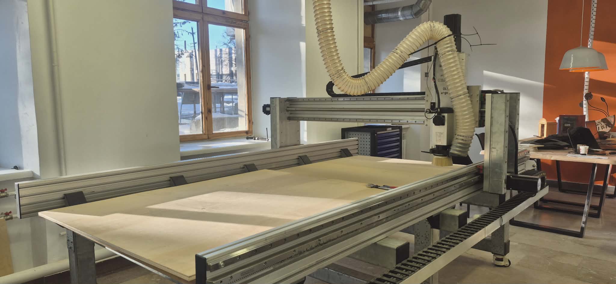
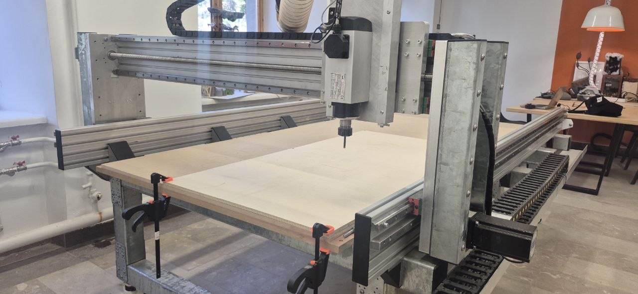
CNC Milling Machine Overview
A CNC (Computer Numerical Control) milling machine is a computer-controlled machine designed for the precise machining and shaping of various materials. The machine operates based on digital instructions that define the tool movement, cutting speed, and machining depth.
Material is removed using a rotating cutting tool, which gradually cuts away excess material to create the desired part. CNC technology provides high accuracy, repeatability, and efficiency, allowing the same part to be produced consistently multiple times.
Machine Axes
The CNC machine operates using three main axes:
- X-axis – provides movement from left to right.
- Y-axis – provides movement forward and backward.
- Z-axis – controls the vertical movement of the tool and determines the cutting depth.
The combined movement of these three axes allows the machine to produce parts of various shapes and dimensions.
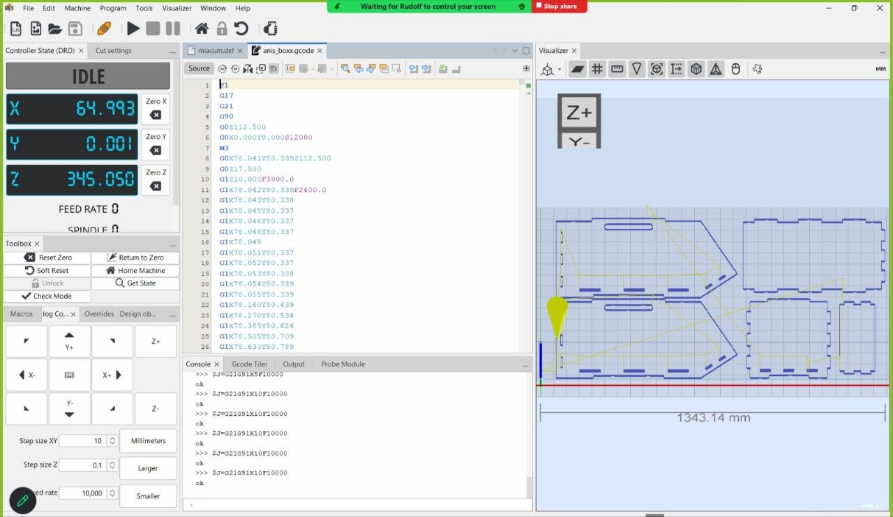
Control Software
The operation of the CNC machine is managed through dedicated control software. This software allows the operator to load G-code files, manually move the machine axes, set the work origin, and monitor the machining process.
Before starting the machining operation, it is important to verify that the correct file has been loaded and that the machine has been positioned properly.
CNC Workflow
The CNC machining process begins with designing a part in CAD software. The design is then imported into a CAM environment, where toolpaths are created and the required machining parameters are selected.
The CAM software generates a G-code file containing all machine movements and machining instructions. This file is then transferred to the CNC machine, which performs the machining operation by following the programmed instructions.
This workflow ensures accurate, repeatable, and high-quality machining results.
Material Fixing
Before the machining process begins, the workpiece must be securely fixed to the machine bed using screws, clamps, or other fastening elements.
A properly secured workpiece prevents unwanted movement during machining, improves accuracy, and reduces the risk of accidents or damage to the machine and material.
CNC Machine Overview and Safety
Working with a CNC machine requires following several safety rules to prevent accidents and ensure proper operation of the equipment.
Before starting the machine, it is important to check that the workpiece is securely fixed to the machine bed. A loose material can move during machining and cause damage or injury. The cutting tool must also be installed properly and tightened in the spindle.
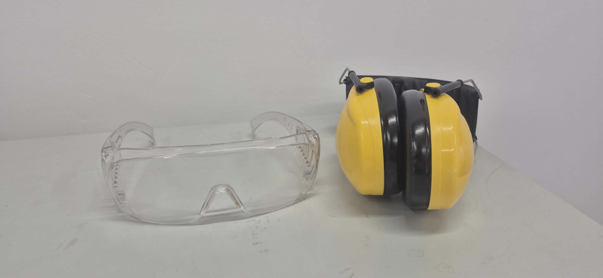
During operation, the operator should always wear appropriate personal protective equipment (PPE) such as safety glasses and hearing protection. Loose clothing, jewelry, or long hair should be secured to avoid getting caught in the moving parts of the machine.
It is also important to keep hands away from the cutting area while the machine is running. The CNC machine should never be left unattended during operation. In case of any unusual sound, vibration, or malfunction, the machine must be stopped immediately using the emergency stop button.
After finishing the job, the machine should be turned off and the working area should be cleaned from chips and dust. Proper cleaning helps maintain the machine and ensures a safe workspace for the next operation.
![]()
It is also important to have a fire extinguisher and a fire blanket available in the workspace in case of a fire emergency, in order to respond quickly and ensure safety.
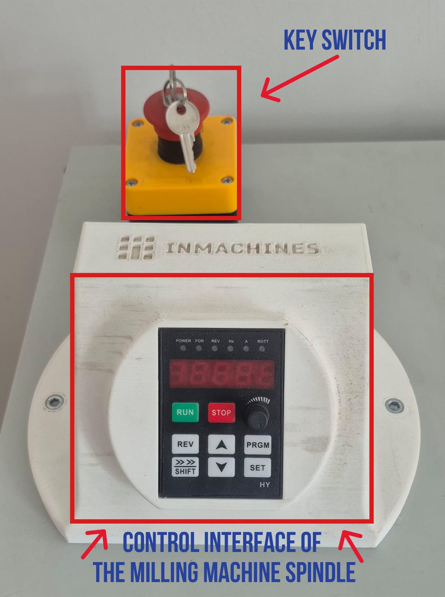
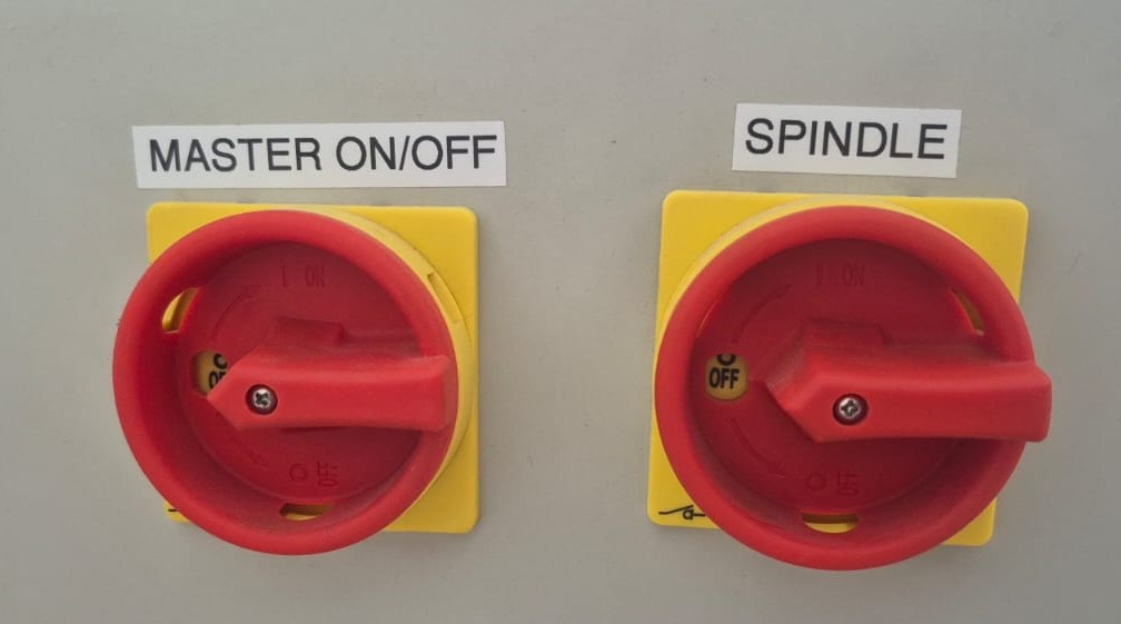
Machine Power Switches
The machine has main control switches, including the MASTER ON/OFF switch, which controls the overall power supply, and the SPINDLE switch, which turns the spindle motor on and off. These switches ensure safe operation and allow the machine to be fully powered down when necessary.
Collet Set
The image shows a set of ER collets used in the milling machine to hold cutting tools.
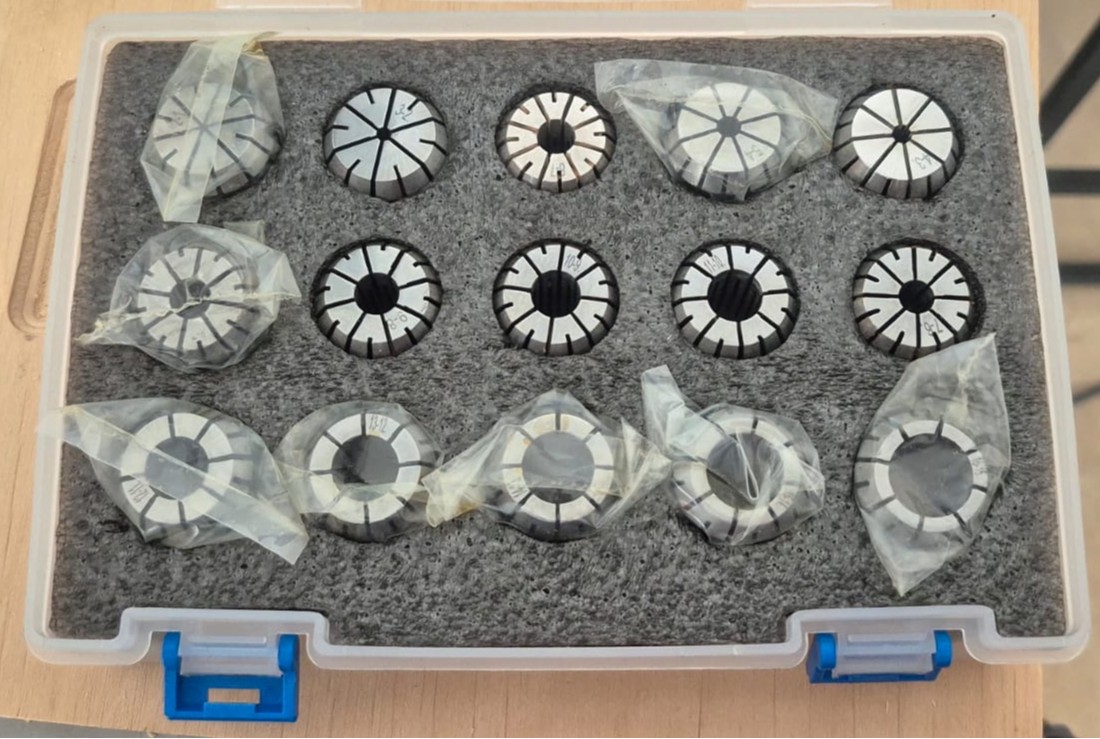
The collets are inserted into the spindle and securely clamp the milling bit or cutting tool. Different collets are designed for different tool diameters to ensure precise and stable machining.
Types of Milling Bits
In CNC machining, several types of cutting bits are used. The most common ones are upcut, downcut, and straight bits. Their working principles are described below.
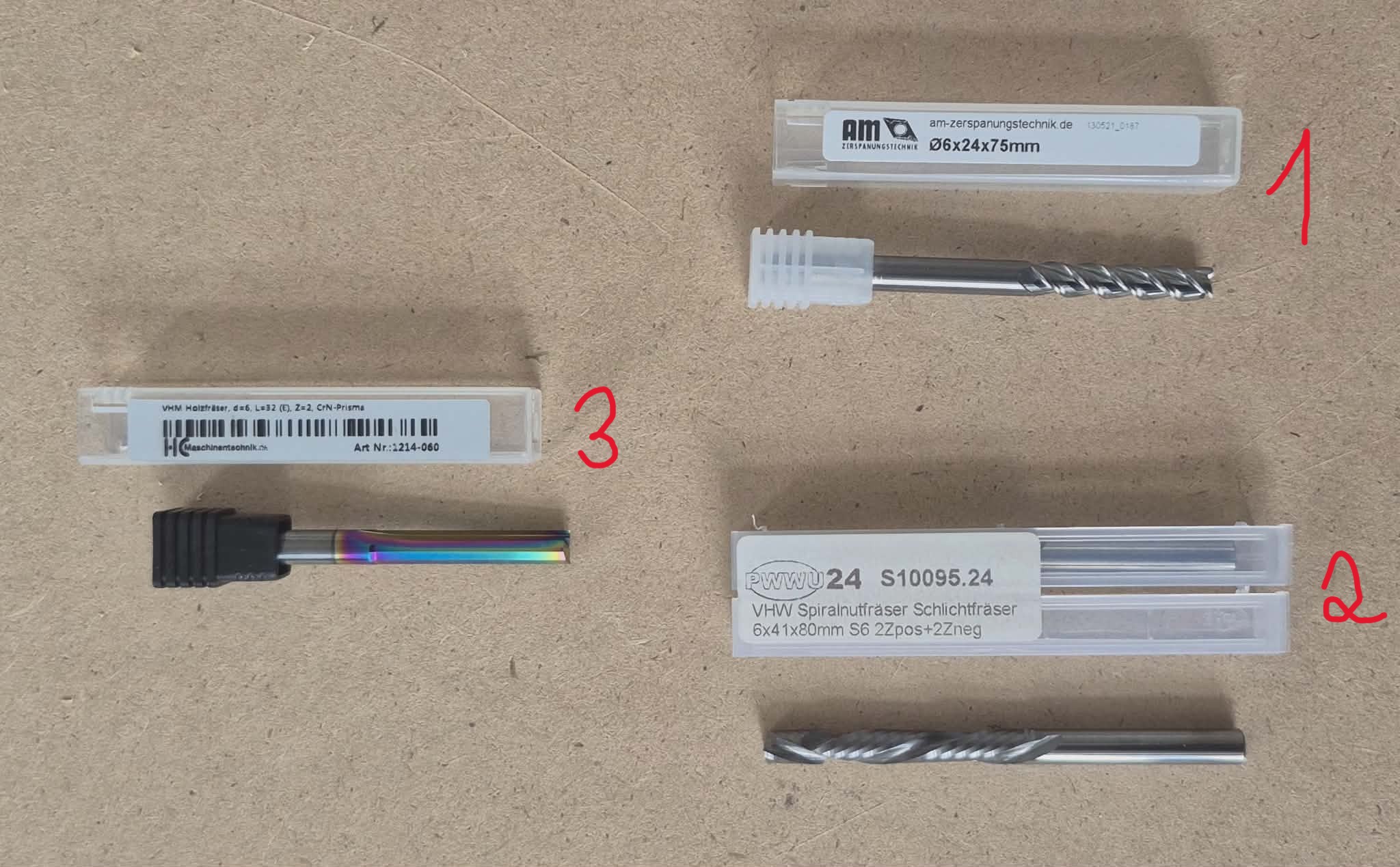
1. Upcut bits pull the chips upward while rotating clockwise. This helps remove the cutting debris efficiently from the cut. However, if the bit is worn, the upper surface of the machined part may not be very clean.
2. Compression bits combine both upcut and downcut geometries in a single tool. The lower part of the bit pulls chips upward, while the upper part pushes the material downward. This design provides clean edges on both the top and bottom surfaces of the material, making compression bits especially suitable for cutting plywood, laminated boards, and other sheet materials. Since the upper section acts as a downcut bit, it helps reduce tear-out on the top surface while maintaining efficient chip evacuation through the lower upcut section.
3. Straight bits have straight cutting edges and do not direct the material either upward or downward during cutting. They are commonly used for general cutting operations, grooves, and simple shapes. Compared to upcut and downcut bits, chip removal is less efficient, which can sometimes affect the cutting quality.
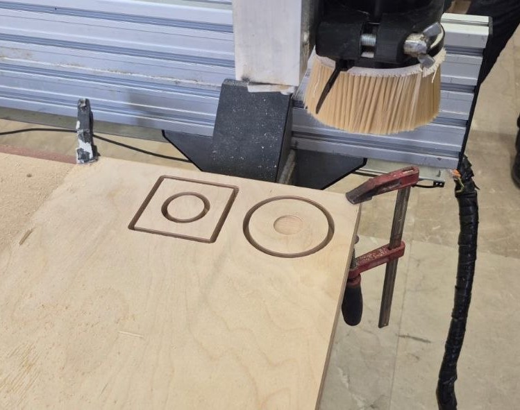
Test Machining
After becoming familiar with the main components of the CNC machine, the safety procedures, and the different types of milling bits, we carried out a test machining operation to better understand the complete CNC workflow in practice.
The main objective of this test was to become familiar with the steps involved in machine preparation, material fixation, setting the work origin, loading the machining file, and executing the machining process. This practical exercise helped us understand how theoretical knowledge is applied in real working conditions and allowed us to evaluate the quality of the final result.
Preparing the Machining File and Creating Toolpaths in Aspire
Before starting the test machining operation, it was necessary to prepare the machining file and create the toolpaths in Aspire. During this stage, the dimensions of the material, the work origin, and the main machining parameters were defined to ensure the safe and accurate operation of the CNC machine.
To start working in Aspire, you first need to create a new project (New Project).
Next, set the main parameters of the working area:
- Length
- Width
- Thickness
In the following step, define the Z Position (0), which can be set either:
- on the machine table surface, or
- on the material surface, depending on the machining requirements
The X/Y (0) origin point should be set at the bottom-left corner to ensure it matches the CNC machine’s zero position.
The file can then be imported (Import), which is a reliable method for loading the design into the project.
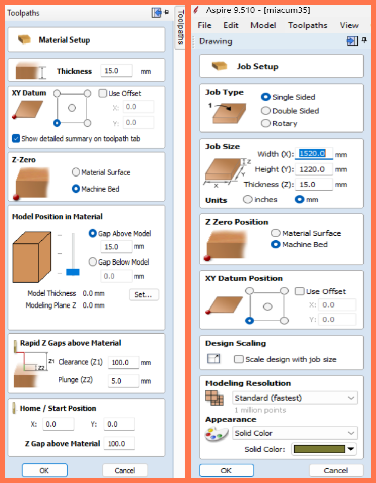
After that, go to the Toolpath tab and open the Material Setup Settings, where safety and working parameters are defined:
- Clearance (Z1) — 100 mm (safe height)
- Z Gap Above Material — 100 mm
These settings ensure that the tool moves safely above the material surface, preventing damage and ensuring proper operation.
Creating the Toolpath
After configuring the material settings, the toolpath was created. During this stage, the machining strategy was selected, the cutting tool parameters were defined, and the required machining values were configured.
Creating the toolpath is one of the most important steps in CNC machining, as it determines the tool movements, cutting depth, and machining sequence.
After verifying all parameters, the toolpath was generated. This toolpath was later used to create the G-code file required for operating the CNC machine.
G-code Generation
After creating the toolpaths and verifying all machining parameters, the final G-code file was generated in Aspire. G-code is a set of instructions that contains information about tool movements, cutting depths, feed rates, spindle operation, and other machining actions. During the machining process, the CNC machine follows these instructions to perform the programmed operations.
CNC Machine Setup and Preparation
The generated G-code file was then imported into Universal G-code Sender (UGS), which is used to establish communication with and control the CNC machine.
In some cases, the computer may not recognize the machine immediately after it is powered on. In such situations, it is necessary to perform the initial configuration of UGS. To do this, the Machine → Setup Wizard menu was opened, and the software was configured step by step. During the setup process, the Enable Homing and Enable Soft Limits options were activated.
Before starting the machining process, the machine position was checked. If the machine had lost its coordinate information, for example after a power interruption, the Home Machine command was used to return the machine to its home position and restore the coordinate system. With the current configuration, the X and Y origin (0,0) is located at the bottom-right corner of the machine bed.
The next step was defining the work coordinates. First, the X and Y axes were zeroed according to the selected reference point.
To set the Z-axis zero position, a touch probe was placed on the surface of the workpiece.
The milling tool was positioned above the probe, and the probing cycle was initiated through UGS. Once the tool made contact with the probe, the system automatically detected the exact position and set the material surface as the Z-axis reference.
If necessary, the Z-axis position could also be adjusted manually. For greater positioning accuracy, the Step Size Z value was reduced from 1 mm to 0.1 mm. The tool was then gradually lowered until it reached the desired position, after which the Zero Z command was used to define the current location as the Z-axis origin.
After all coordinates had been defined and the machine settings verified, the CNC machine was ready to begin the machining process.
Machining Process
After completing the machine setup and verifying the work coordinates, the G-code file was loaded into UGS and the machining process was started.
During machining, the CNC router followed the previously generated toolpaths and gradually removed material according to the specified cutting depths, feed rates, and other machining parameters. Throughout the process, the tool operation and cutting quality were continuously monitored to ensure that the job was performed correctly and safely.
Once the machining process was completed, the machine returned to its final position and the finished part was removed from the work area. The final result was then inspected to evaluate dimensional accuracy, cut quality, and overall conformity with the original design.
Measurement Results
After machining, measurements were taken to evaluate the accuracy of the CNC process and verify the dimensional consistency of the produced part.
The measurements were performed using a caliper. Both the outer diameter of the circular part and the dimensions of the corresponding cutout were inspected. The machined part was compared with the remaining opening in the plywood to assess the quality and precision of the cutting process.
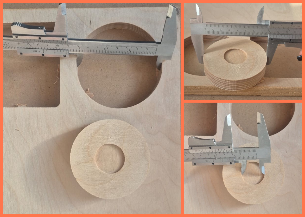
The results showed that the dimensions of the part closely matched those of the corresponding opening, taking into account the acceptable tolerances of the CNC machining process and the influence of the tool diameter. The cut edges were clean, and no significant dimensional deviations were observed.
These measurements confirmed that the selected machining parameters, tooling, and machine setup were appropriate for the operation, and that the final part accurately reflected the intended design geometry.
You can find the detailed information on the group page.
Individual Assignment
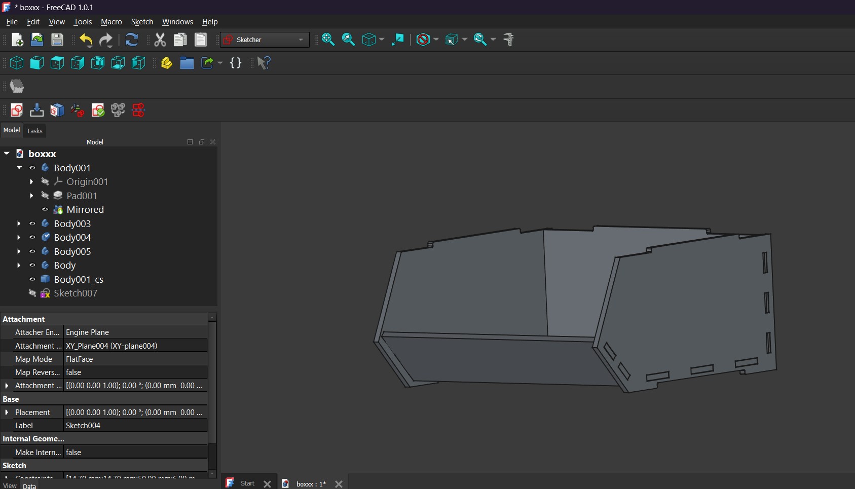
Parametric Design Approach
After completing the group assignment and verifying the CNC machine operation through a series of test cuts, I moved on to my individual project.
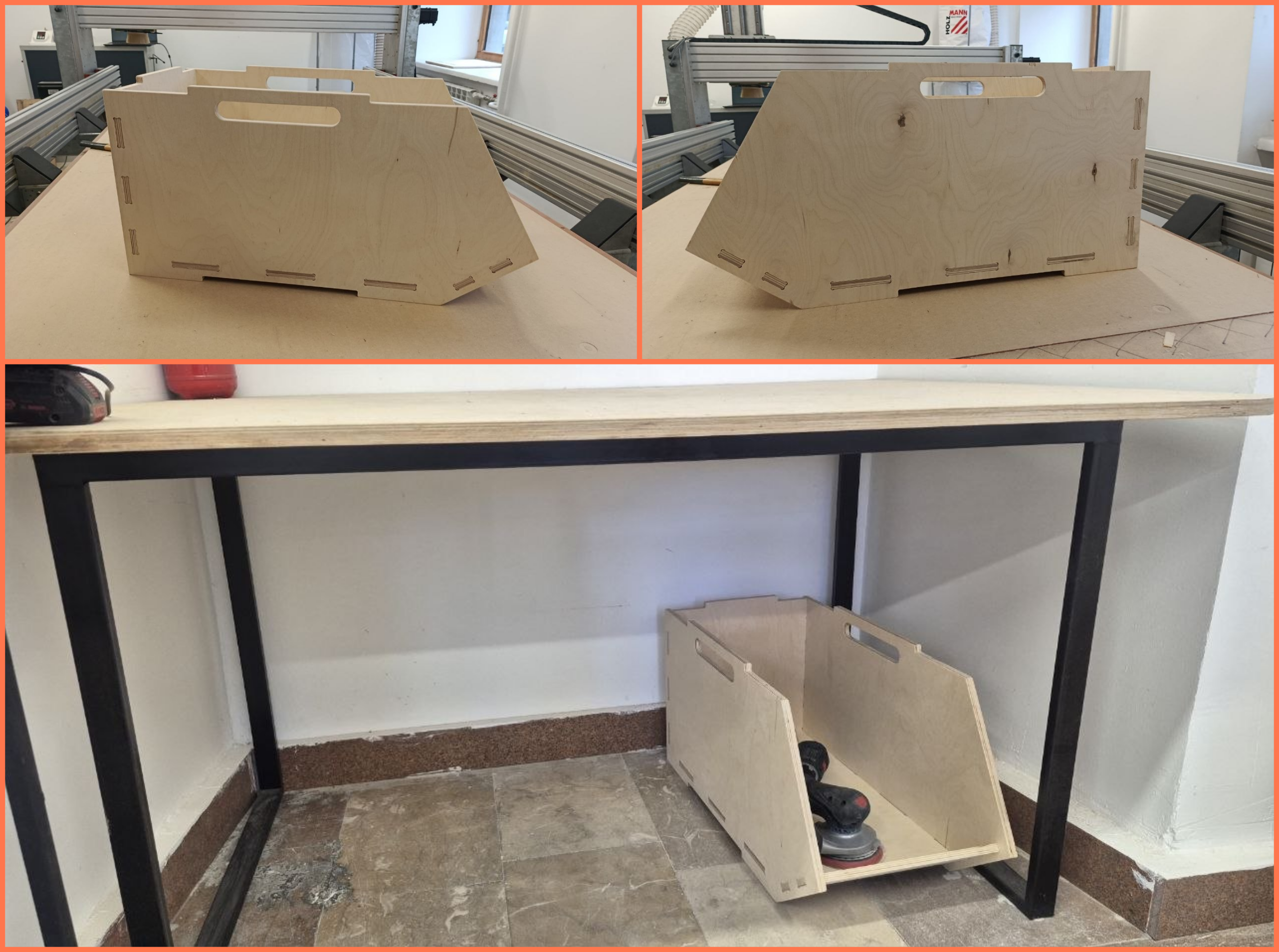
As part of this week’s assignment, I decided to design and fabricate a storage box using the CNC machine. The goal of the project was to create a structure that could be cut from sheet material and later assembled easily.
At the initial stage, I had already determined the exact dimensions of my project, so I did not create the model using a parametric approach. All dimensions were predefined, and I did not expect to modify them later.
However, I later realized that if I needed to change the dimensions of the project, I would have to edit each part and dimension individually, which would be a time-consuming process. Therefore, I decided to redesign the model using a parametric approach, allowing all key dimensions to be controlled through parameters and making future modifications quick and easy.
For this purpose, I created a spreadsheet where I defined the main parameters, such as the material thickness, overall dimensions, and the sizes of individual parts. This approach allowed the entire design to automatically adapt to new values whenever a change was made, without the need to modify each element separately.
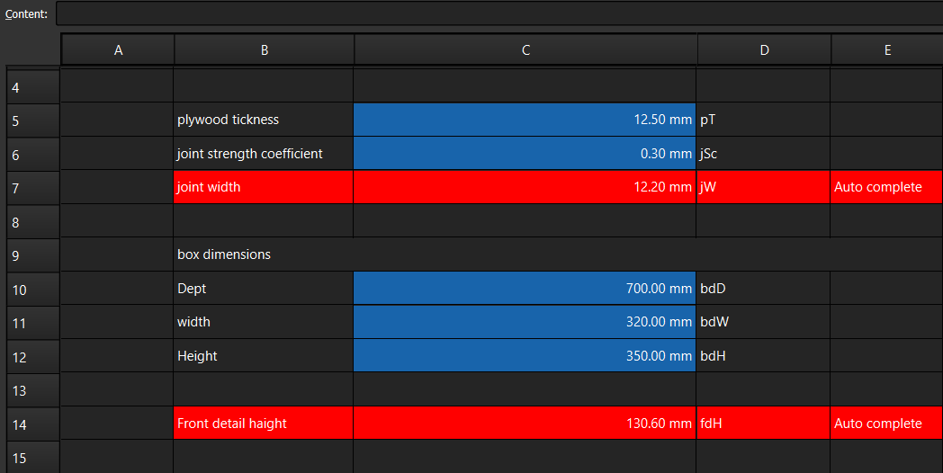
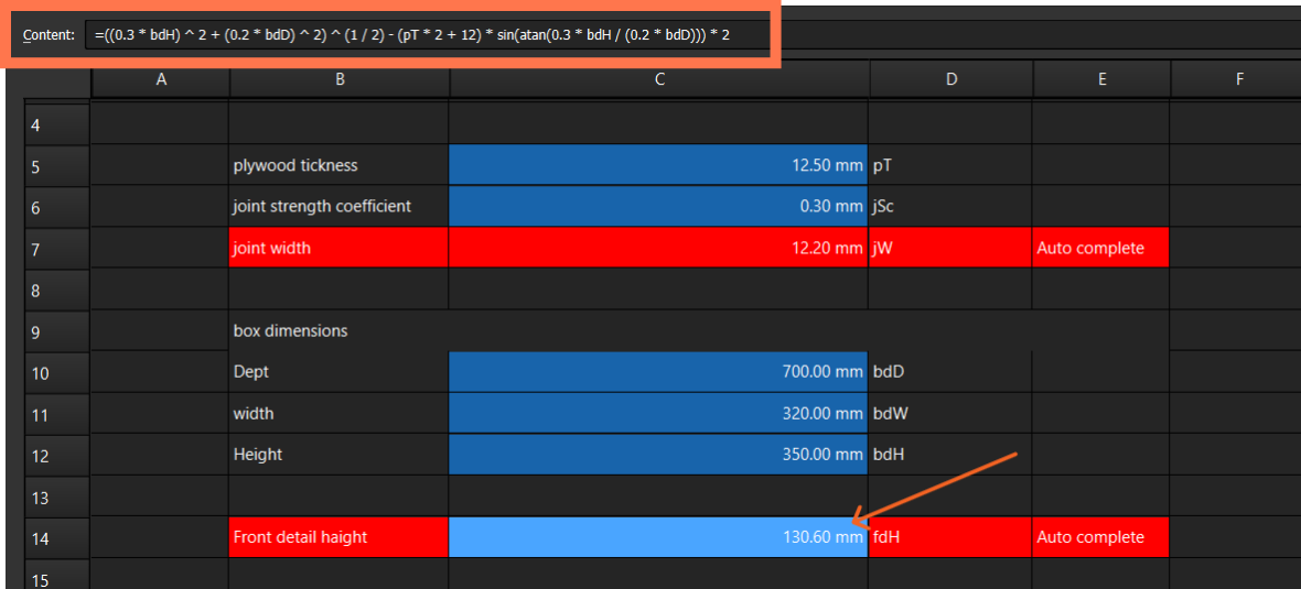
In addition to the main parameters, I also defined values that are calculated automatically. For example, I set the joint width as a value dependent on the material thickness, so that the width of the joints always matches the material being used. Similarly, I defined the front detail height parameter, which is calculated based on the overall height and other dimensions.
Since my design included an inclined section, it was necessary to determine its angle precisely. For this purpose, I performed the appropriate mathematical calculations to obtain the value of the angle of the slanted line.
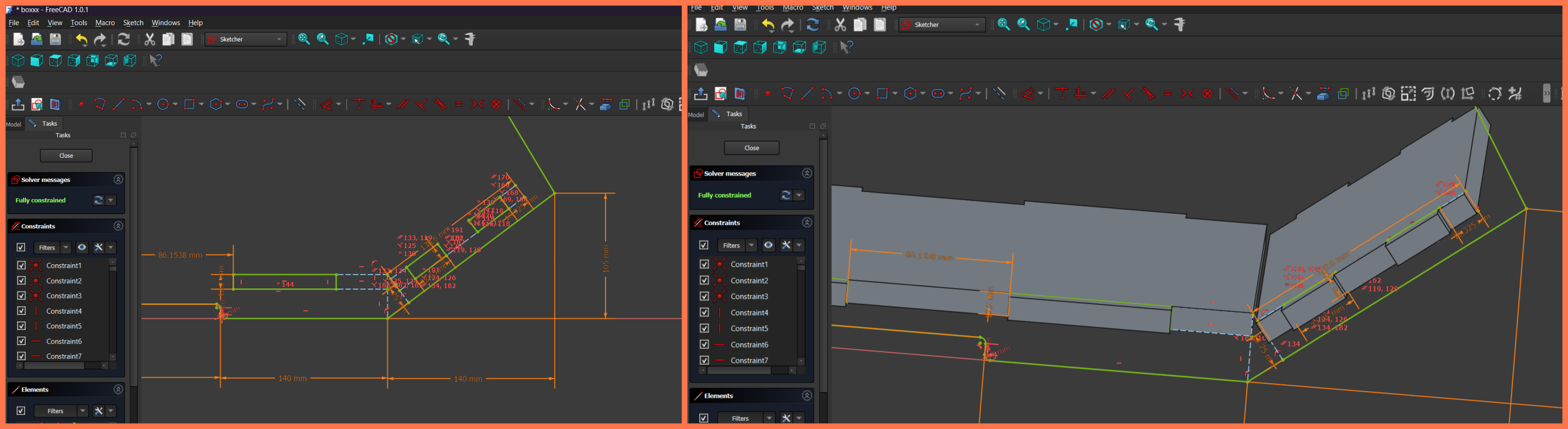
This calculation was important to ensure that the bottom plane of the design and the front closing part do not interfere or collide with each other, thereby ensuring correct assembly and proper functionality of the structure.
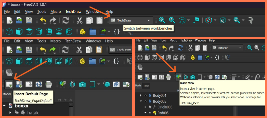
After completing the design phase, the next step is the export process, aimed at obtaining the technical representation of the project. For this purpose, the Tech Draw environment is used, where a new page is first created (New Page), and then the appropriate views of the model are inserted into the drawing workspace using the Insert View tool**, ensuring an accurate and dimensionable representation.
G-code Generation and Setup
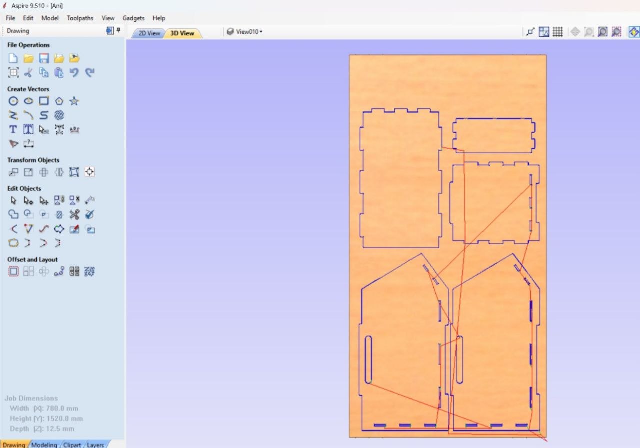
In Aspire, I first imported the DXF file and created a new job, specifying the dimensions and thickness of the plywood to be used.
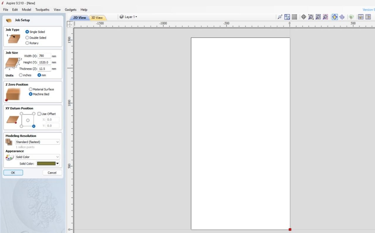
Then I checked that all the parts were sized according to the project and were correctly positioned in the work area.
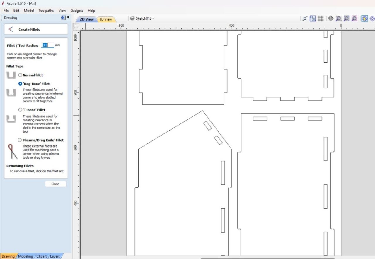
In the next step, I created the toolpaths needed for the CNC machine. Then I marked the locations of all the joints and added Dog Bones. I used them both on the inside corners of the joints and on some sharp corners so that the cut parts could be easily assembled and fitted accurately.
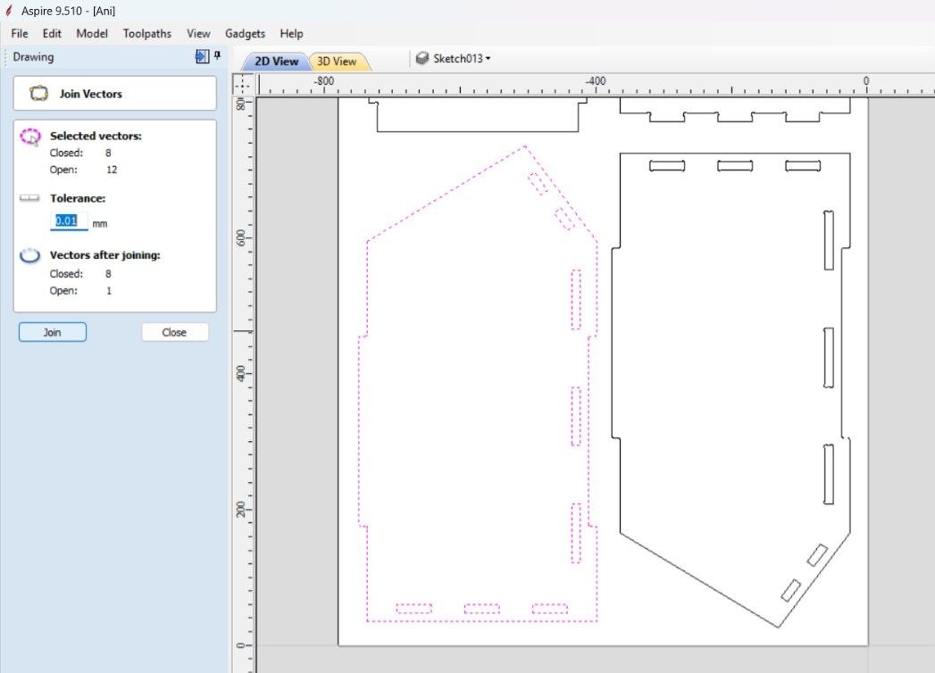
The imported file also contained Open Vectors, which Aspire marked as unconnected sections. I connected these lines so that all the contours were closed and suitable for further processing.
Since all the parts had to be completely separated from the plywood sheet, I used the Profile Toolpath tool, defining the cut along the outside of the parts. The material used was 12.5 mm thick, but I set the cutting depth to 13 mm to ensure that all parts were completely cut and easily separated from the main sheet.
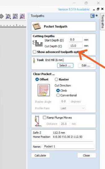
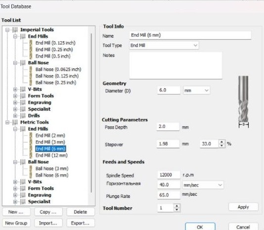
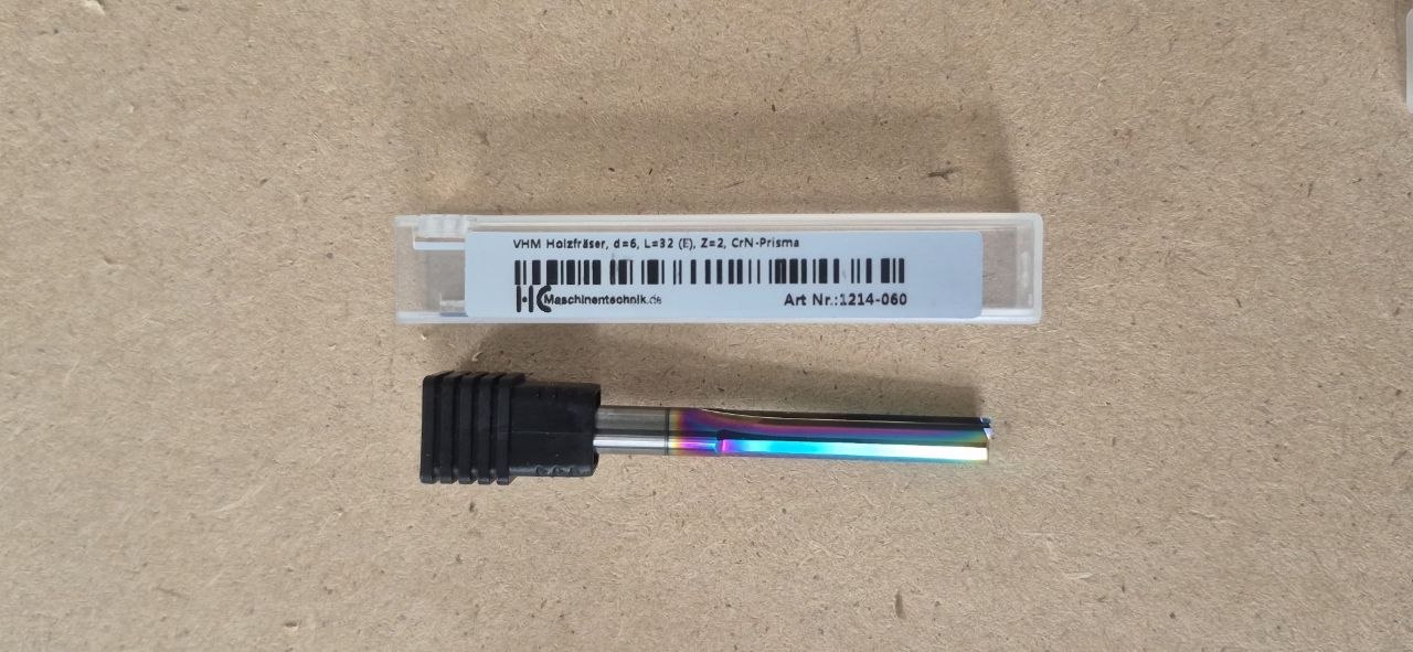
To prevent the parts from moving during cutting, I added Tabs (bridges) that hold the parts connected to the main sheet until the end of processing. All cutting operations were to be performed using a 6 mm diameter End Mill.
After setting all the parameters, I calculated the toolpaths and used the Preview Toolpath function to see the processing process in advance and make sure that all parts would be cut correctly.
Finally, I saved the toolpaths in a format suitable for the CNC machine and prepared the files for further processing.
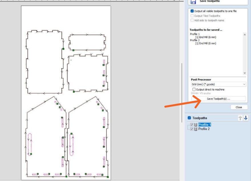
I opened the exported G-code file in UGS (Universal Gcode Sender), the CNC machine control environment. Then I checked that all the toolpaths were imported correctly and corresponded to the previously created Toolpaths.
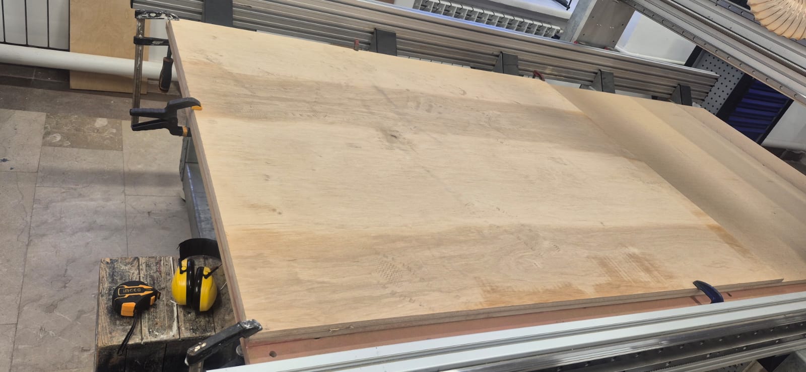
Before starting the machining process, I placed a 780 × 1520 mm plywood sheet on the CNC machine worktable.
After positioning the sheet, I firmly fixed it to the worktable to prevent any movement during machining. Proper and stable fixation of the material was essential both for ensuring cutting accuracy and for maintaining safe machine operation.
After that, I performed the initial machine setup by executing the Home process and setting the zero points (Zeroing) on the X, Y, and Z axes. The Z-axis zero point was taken directly from the surface of the plywood to ensure an accurate cutting depth.
However, I later noticed that the positioning of the part in the G-code file was incorrect, since the X and Y axes were set in the opposite direction. Therefore, I returned to Aspire, corrected the axis settings, recalculated the toolpaths, and exported the G-code file again. I re-imported the corrected file into UGS, and only then continued the machining process.
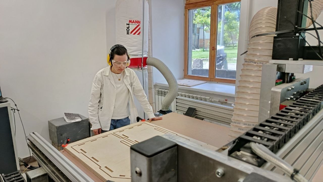
Milling Process
After that, I turned on the spindle, setting the speed to 12,000 RPM (shown as 230 on the control screen).
Then I turned on the vacuum system to remove dust generated during machining, put on safety glasses and ear protection, and started monitoring the CNC machine during operation.
Cleaning and Post-Processing
After the machining process was completed, I turned off the spindle. Then I removed the cut parts from the CNC machine table.
Using a trimming tool, I cleaned the remaining tab marks from the edges.
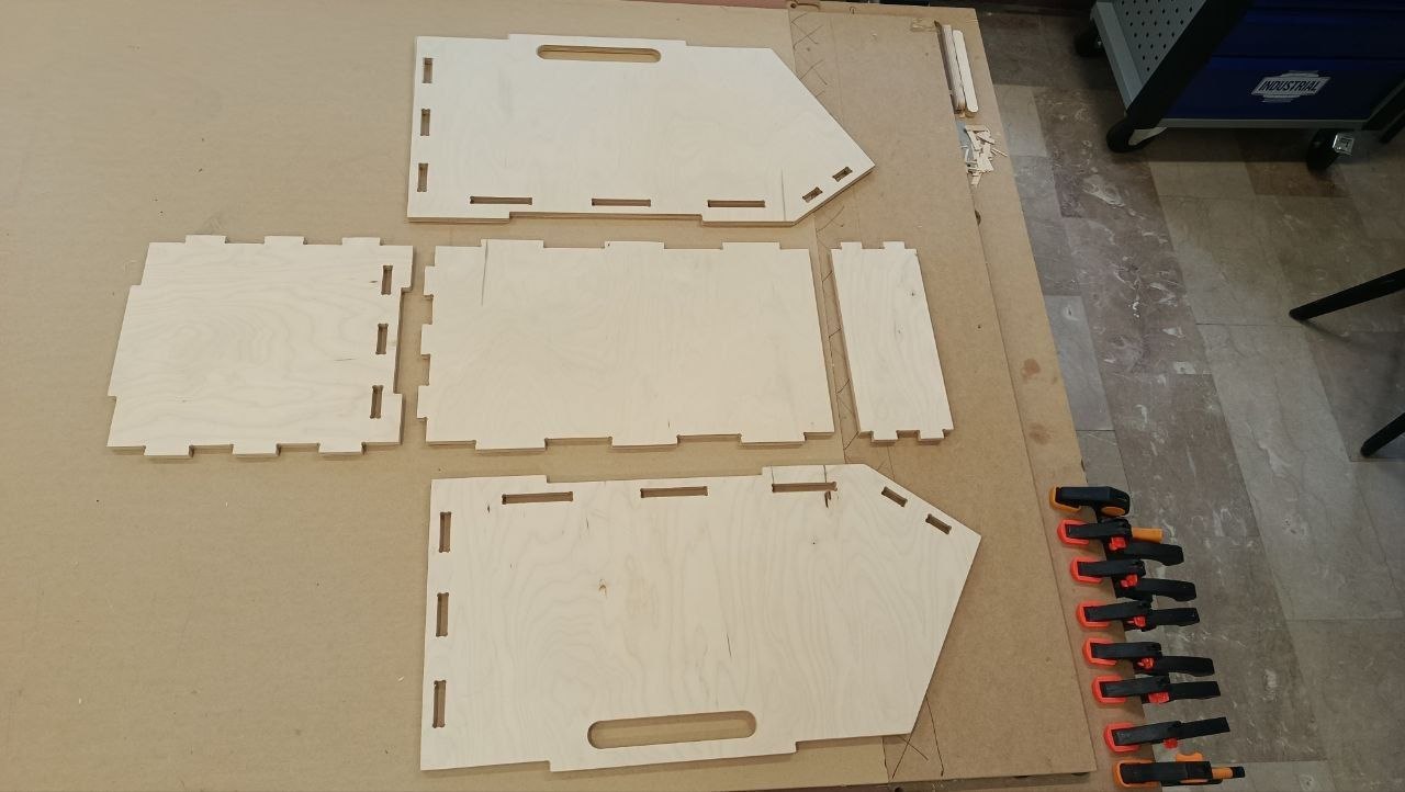
Finally, I lightly sanded the surfaces and smoothed the sharp edges to improve the finish and ensure safe handling.
Assembly
Then I assembled all the parts by joining them together in the correct order. During the assembly process, I used a rubber mallet to help the pieces fit into place more easily and to ensure tight joints. As a result, the parts fit well together and formed a stable and solid structure.
Conclusion
In this week, I learned the full workflow of CNC computer-controlled machining, starting from digital design and toolpath generation in Aspire, all the way to machine setup, zeroing, and physical fabrication. Through both the group and individual assignments, I gained practical experience in operating the CNC machine safely and correctly, including material fixation, tool selection, and machine calibration.
The most important part of the process was understanding how small mistakes in setup (such as incorrect axis orientation in G-code) can affect the entire machining process, and how to identify and correct them through iteration in the CAM software. This helped me better understand the relationship between digital design and real-world manufacturing.
In the individual project, I applied parametric design principles to create a flexible model, which later simplified adjustments and improved design efficiency. The final result was a successfully fabricated storage box with precise joints and a stable assembly, demonstrating accurate machining and proper toolpath planning.
Overall, this week significantly improved my confidence in CNC workflows and helped me develop a more systematic approach to digital fabrication.