Final Project
ERKXOSUTYUN (Dialogue)
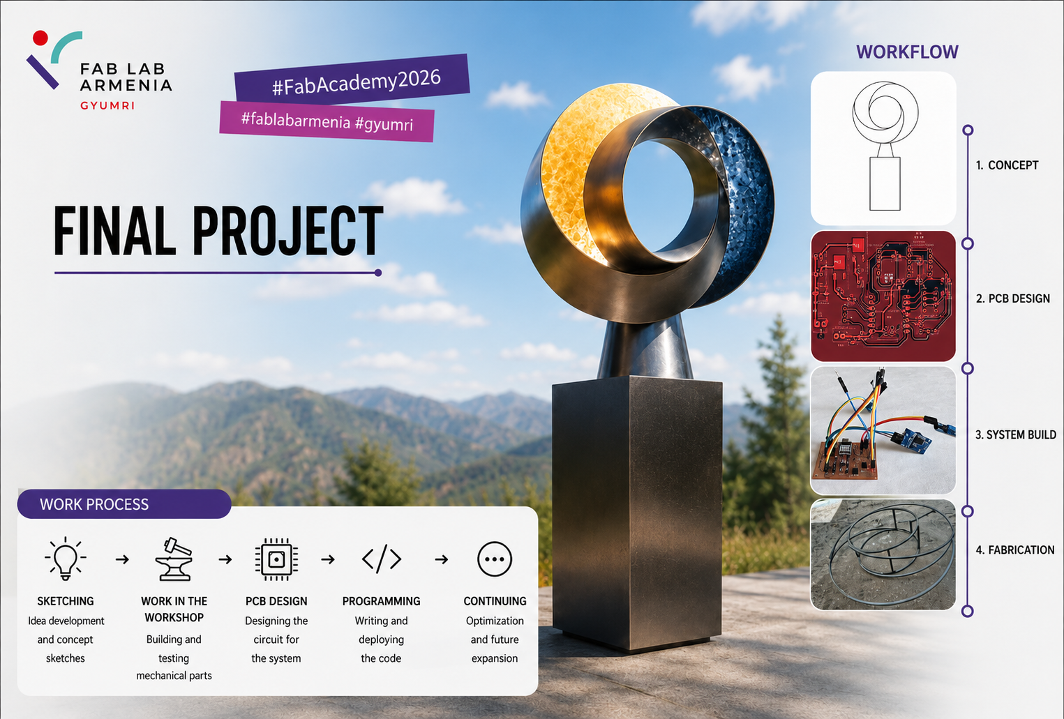
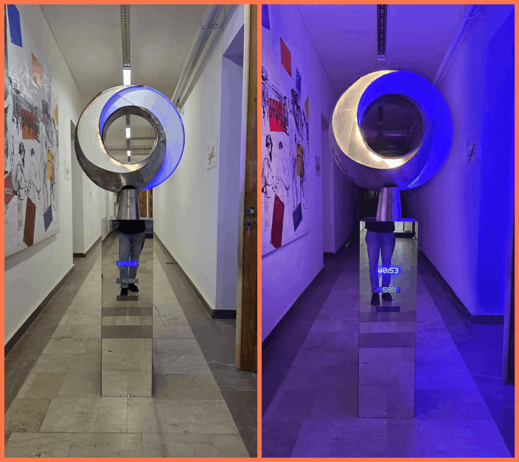
My final project is ERKXOSUTYUN (Dialogue) — an interactive outdoor light object built around the contrast between light and darkness, day and night. During the day it exists as a quiet sculptural form, emphasizing geometry, materials, and the interaction between sunlight and the structure itself. At night, it “awakens” — internal LED lighting activates and the object begins actively responding to its environment, with light becoming its primary medium of communication.
What does it do
An LDR sensor continuously measures ambient light levels and determines whether it is day or night: when darkness falls, the LED lighting system automatically activates, and as daylight increases the lights turn off again. A DHT11 sensor provides temperature and humidity readings, and a DS3231 real-time clock module supplies accurate time data — all of it displayed in real time on MAX7219 LED matrix displays mounted behind a mirrored, light-diffusing surface.
The whole system runs on a custom PCB built around a Seeed Studio XIAO RP2040, housed inside a metal structure that also supports the lighting and acrylic diffusion panels. Beyond its technical function, the object is meant as a conceptual exploration of natural cycles — translating environmental data into a visual “dialogue” between technology, the environment, and the viewer.
Working Principle
The LDR sensor continuously measures the ambient light level.
During daylight, the measured value remains above the defined threshold, and the LED lighting stays turned off. When the surrounding light decreases during sunset, the sensor value drops below the threshold and the microcontroller automatically activates the LED strips.
When daylight returns, the sensor detects the increase in light intensity and switches the lighting off again.
This creates an automatic day and night lighting system that responds to environmental changes without user interaction.
Interesting work done by others
- BruumRuum! (Artec3 / David Torrents, Barcelona) is an interactive public installation that responds to city noise and human voices using LED lighting, changing color and movement depending on sound intensity — this was the main reference that showed how light can become a medium for communication rather than simply illumination.
- Proximity Reactive Flower Lamp (GlowSense), a Fab Academy project, uses a proximity sensor and NeoPixel LEDs to respond to human presence by changing color and brightness depending on distance — useful for thinking through how sensor input maps to visual output.
Concept and Early Sketches
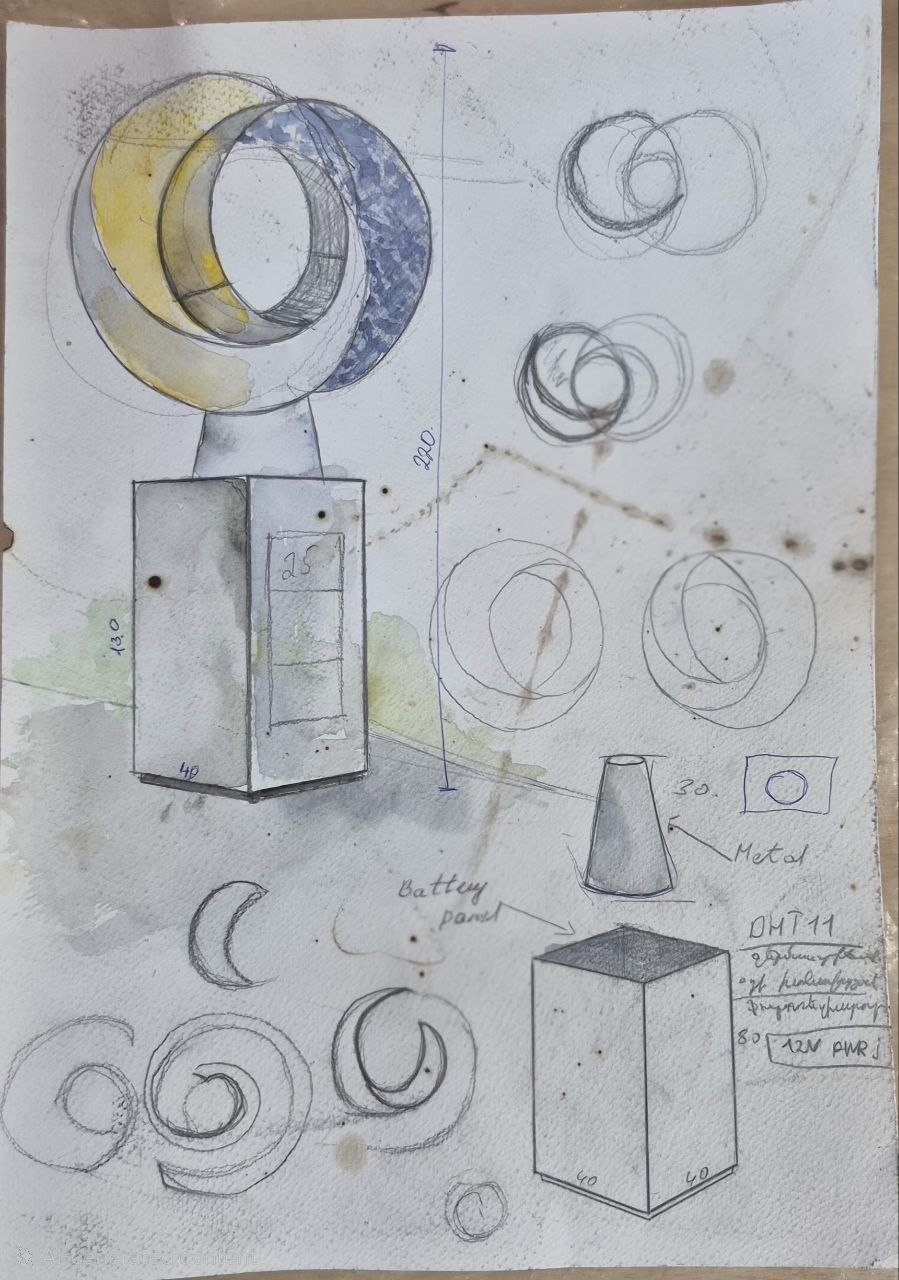
The concept for this project was first developed during Week 1, when I created the initial concept sketch.
The original idea was to build an interactive outdoor object that responds to the transition between day and night. At that stage, the project was planned to operate using a solar panel, a rechargeable battery, and a charge controller. As the project evolved, this solution was replaced with a 12 V power supply to improve reliability and simplify the electrical system. Although the power source changed, the core concept of creating a dialogue between light, darkness, and the surrounding environment remained the same throughout the project.
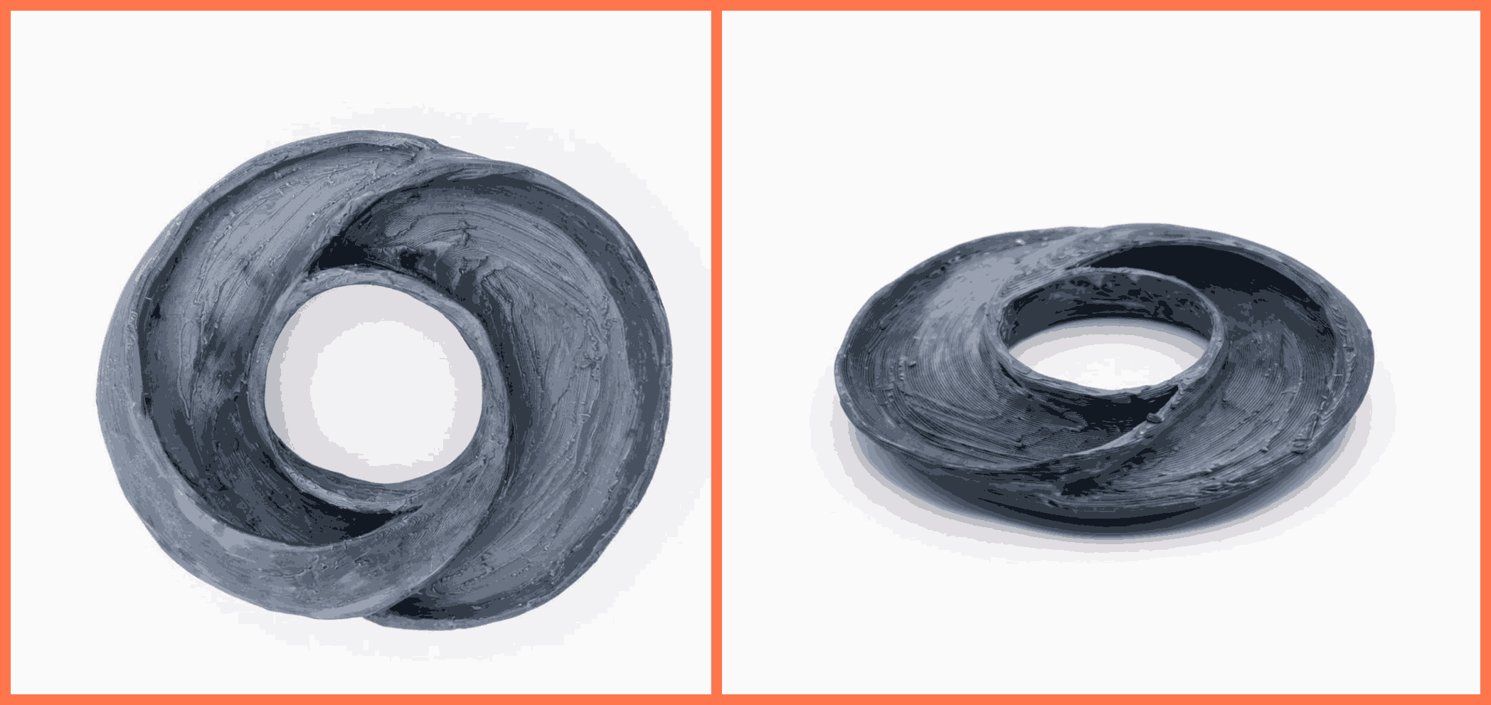
To better understand the overall proportions and three-dimensional form of the object, I also created a small physical concept model using plasticine. This quick prototype allowed me to explore different shapes and proportions before moving on to CAD modeling. Although it was a simple study model, it helped me visualize the overall form and refine the design at an early stage.
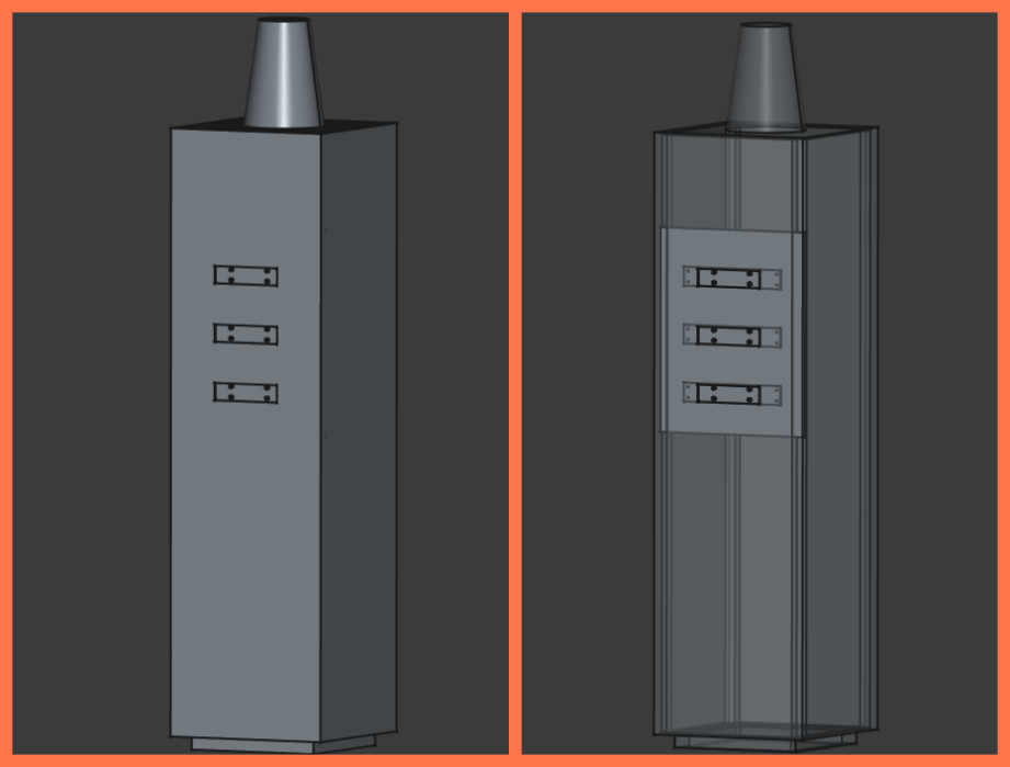
In Week 2, I created the first CAD model of the project in FreeCAD. At that stage, only the lower section of the structure was modeled because the upper part of the design had not yet been finalized and was expected to evolve during the development process.
Later, during Week 9, after redesigning the custom PCB and deciding to replace the original displays with MAX7219 LED matrix modules, I updated the 3D model of the lower section. The enclosure dimensions and mounting features were modified to accommodate the new electronics and ensure proper alignment of the displays inside the project.
Unlike the lower section, the upper part of the structure was never fully modeled in CAD. Its geometry continued to change throughout fabrication as different construction methods and proportions were tested. Instead of creating a complete 3D model, I developed this part using hand sketches and full-scale drawings, which served as references during metal cutting, bending, welding, and assembly. This iterative approach allowed the design to evolve naturally while solving practical fabrication challenges.
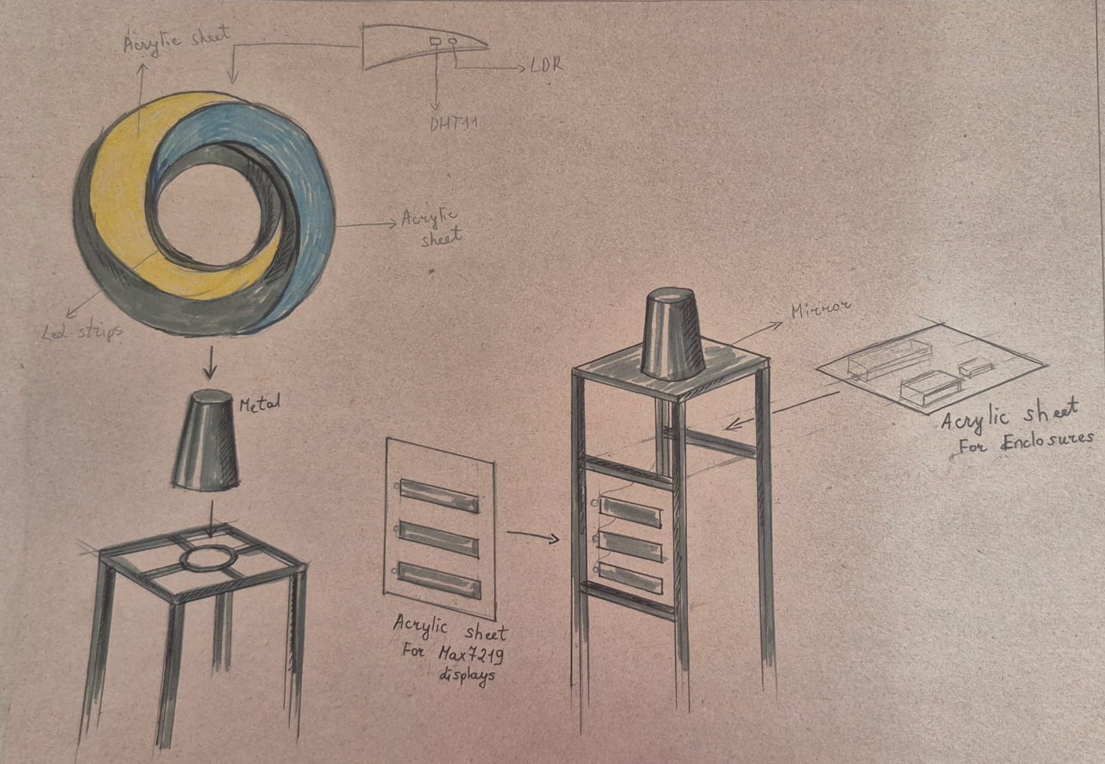
These sketches became the main reference for fabricating the upper structure and demonstrate how the final form developed through a combination of design, prototyping, and hands-on fabrication rather than relying entirely on a digital CAD model.
Choosing the Sensors
The electronic system of the final project was developed by integrating components that work together to collect environmental data, process the acquired information, and control the lighting system.
| Module | Function |
|---|---|
| XIAO RP2040 | Main controller |
| LDR | Ambient light detection |
| DHT11 | Temperature & Humidity |
| DS3231 | Time |
| MAX7219 | Display |
| MOSFET | LED switching |
The reasons for selecting the LDR, DHT11, DS3231 RTC, and MAX7219 modules, along with their operating principles and integration into the system, are described in the Week 6. Later, the electronic system was redesigned during Week 9 to meet the final project requirements and the updated PCB architecture.
Electronics system
Design and Production
The electronics system of my final project was developed throughout multiple Fab Academy assignments. During Week 9, I designed and manufactured the custom PCB, including the electronic schematic, PCB layout, KiCad 3D model, PCB milling, soldering, and initial hardware testing. Later, during Week 15 – System Integration, I integrated all electronic modules into the final system, developed the complete control software, and documented the electronics architecture by creating the block diagram, wiring diagram, and power distribution.
The system is built around the Seeed Studio XIAO RP2040 microcontroller, which serves as the main controller of the project. It receives data from the LDR and DHT11 sensors, communicates with the DS3231 Real-Time Clock (RTC) module, controls the MAX7219 LED matrix displays, and drives the 12V LED lighting through MOSFET drivers.
KiCad Design Files
The custom PCB was designed and manufactured during Week 9. The design process began in KiCad, where I created the electronic schematic defining all system components and their electrical connections.
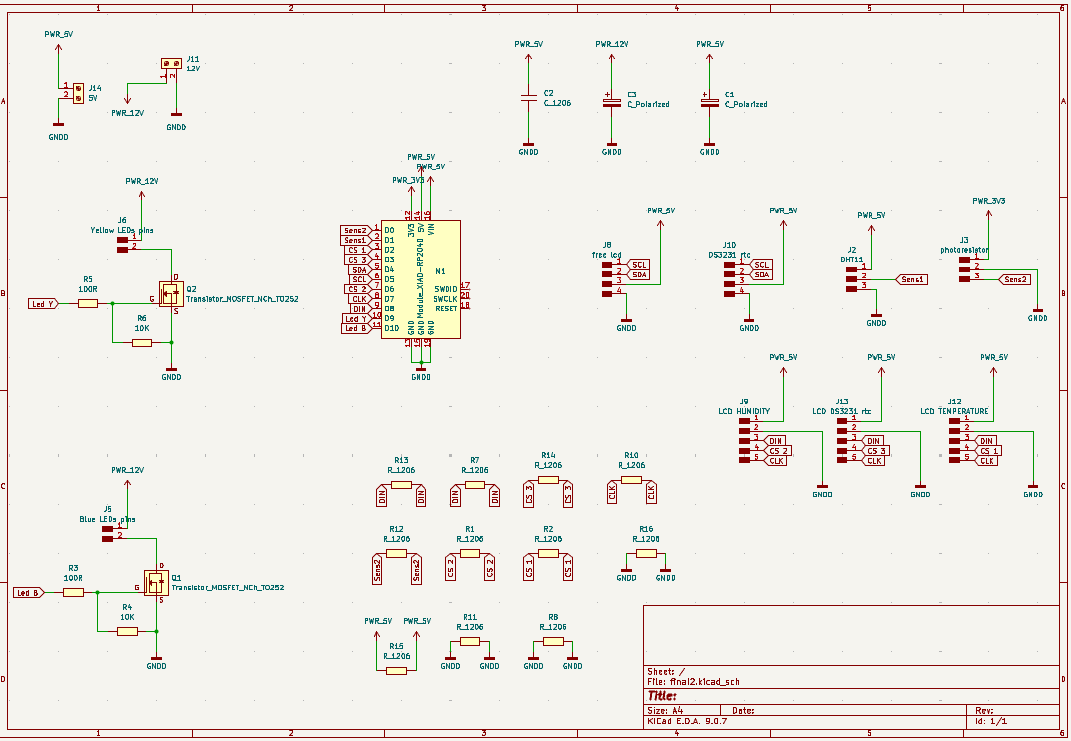
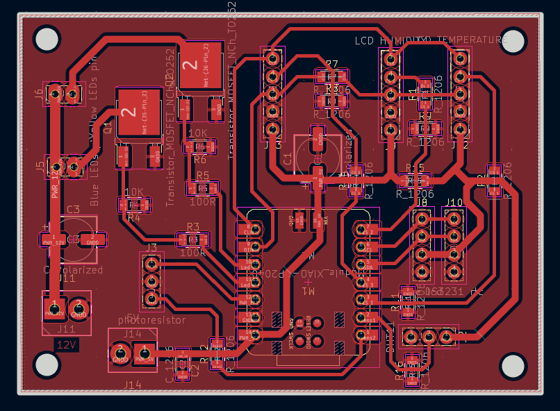
Based on the schematic, I designed the PCB layout, arranging the components and routing the traces to achieve a compact design with convenient connections for the external modules.
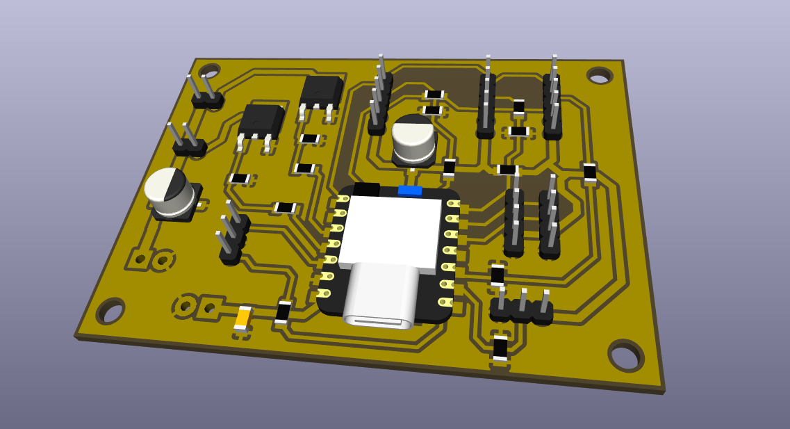
Before manufacturing the PCB, I verified the design using the KiCad 3D Viewer, checking the placement of the components, connectors, and the overall board layout to ensure that it met the project requirements and was ready for fabrication.
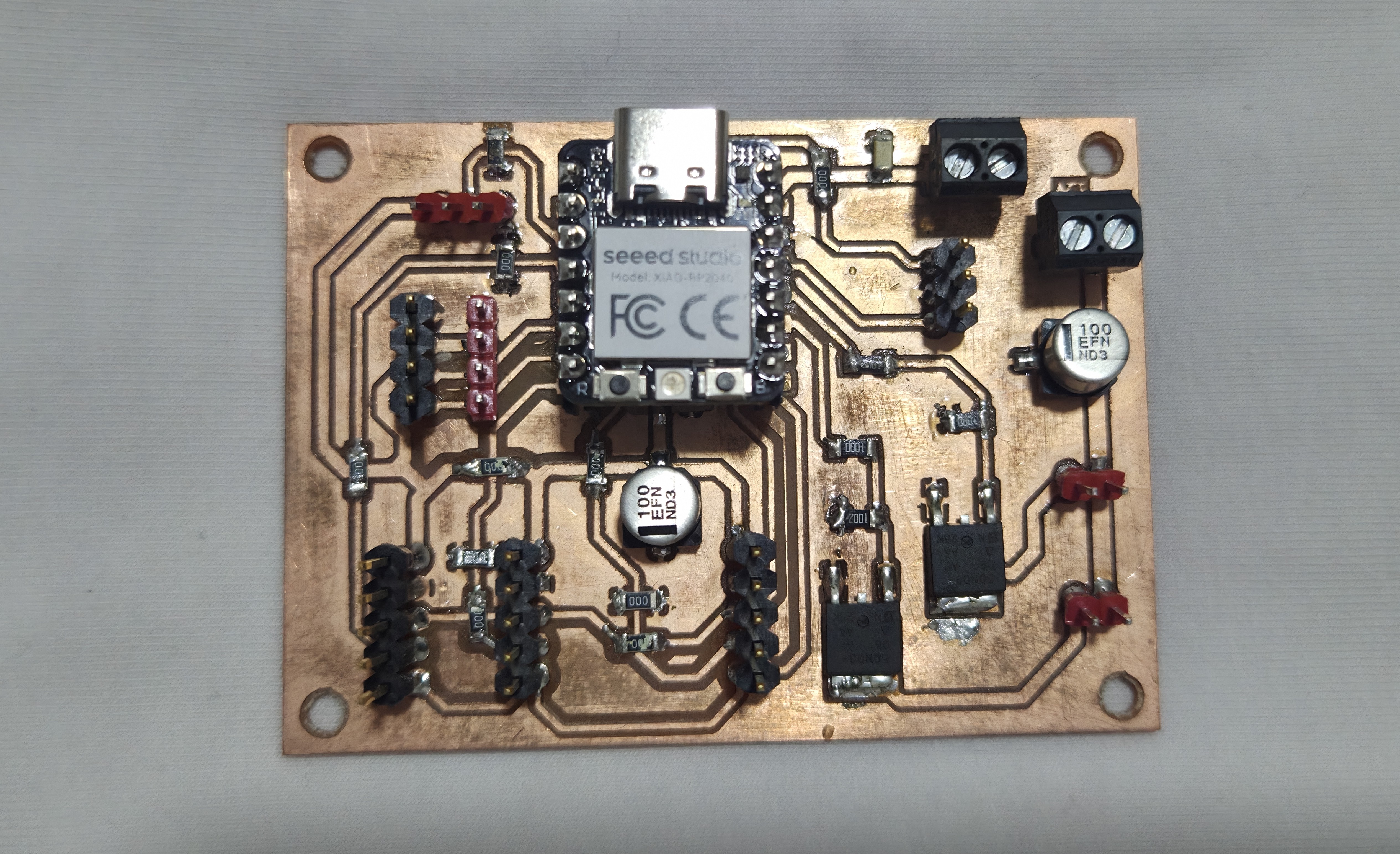
Assembled Board
After manufacturing the PCB, all electronic components were placed and soldered onto the board. The assembled PCB was inspected and tested to verify that the power connections and electronic components were correctly installed.
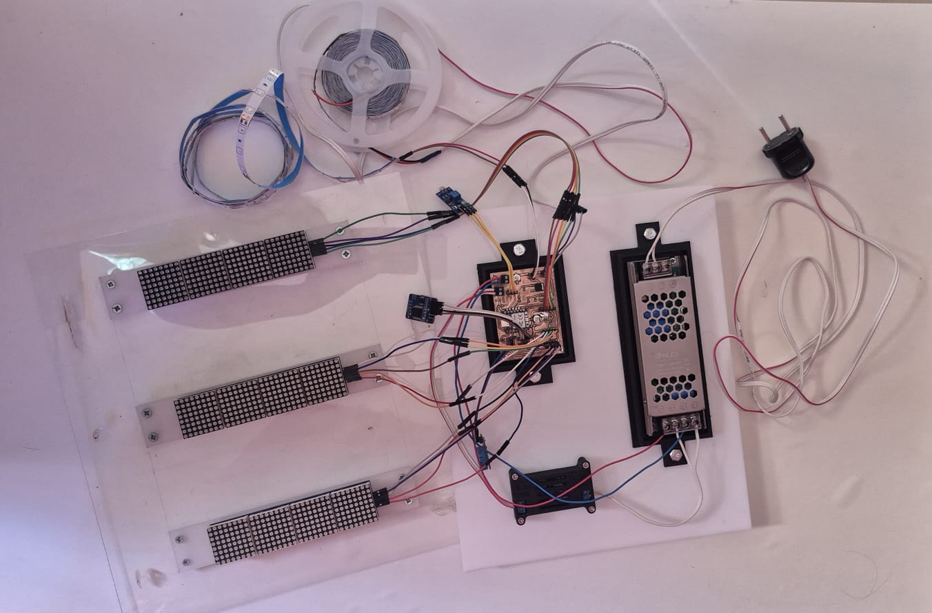
After the initial testing, the external modules were connected to the board, including the LDR and DHT11 sensors, DS3231 RTC module, MAX7219 LED matrix displays, and the LED lighting control section for the final system integration.
Circuit and Block Diagram
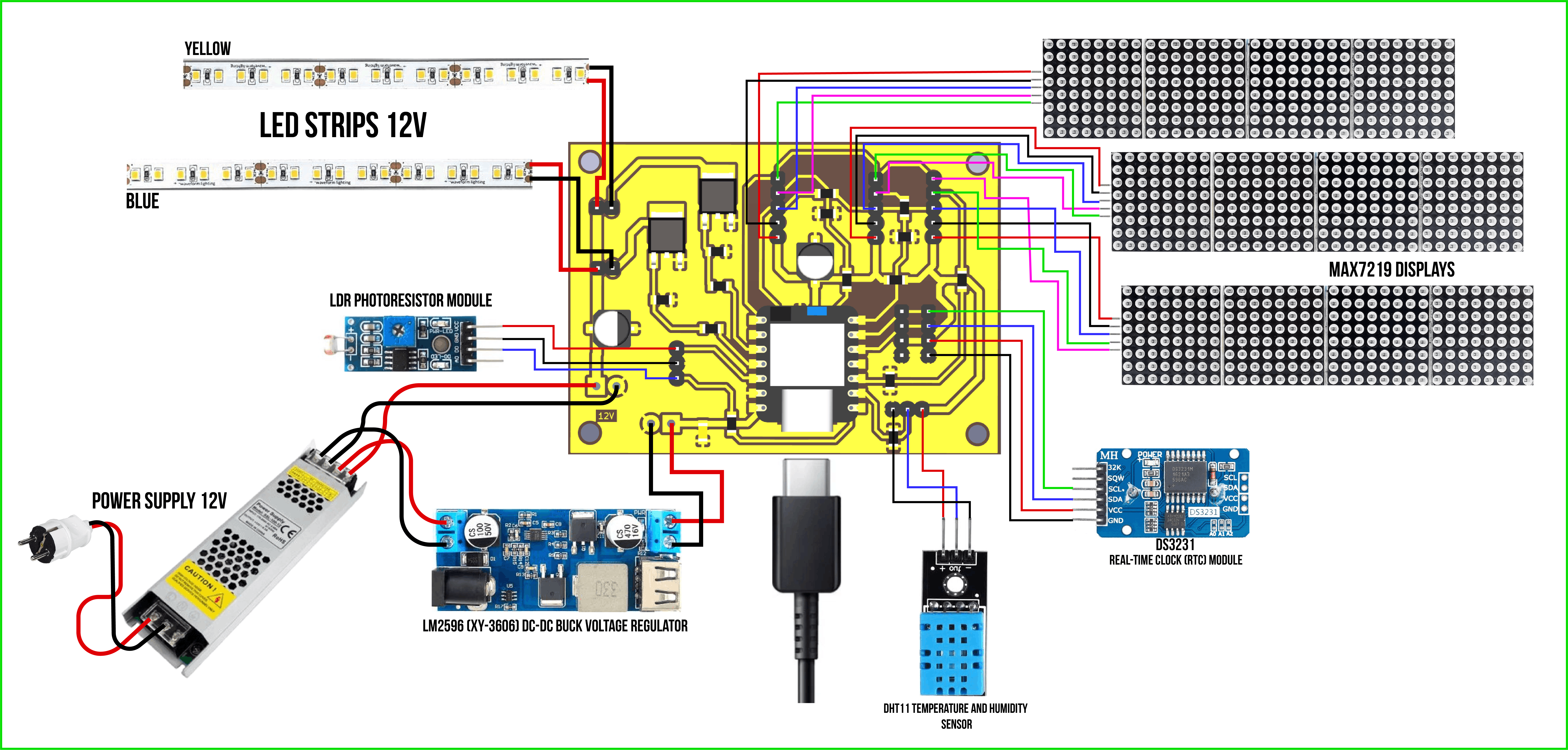
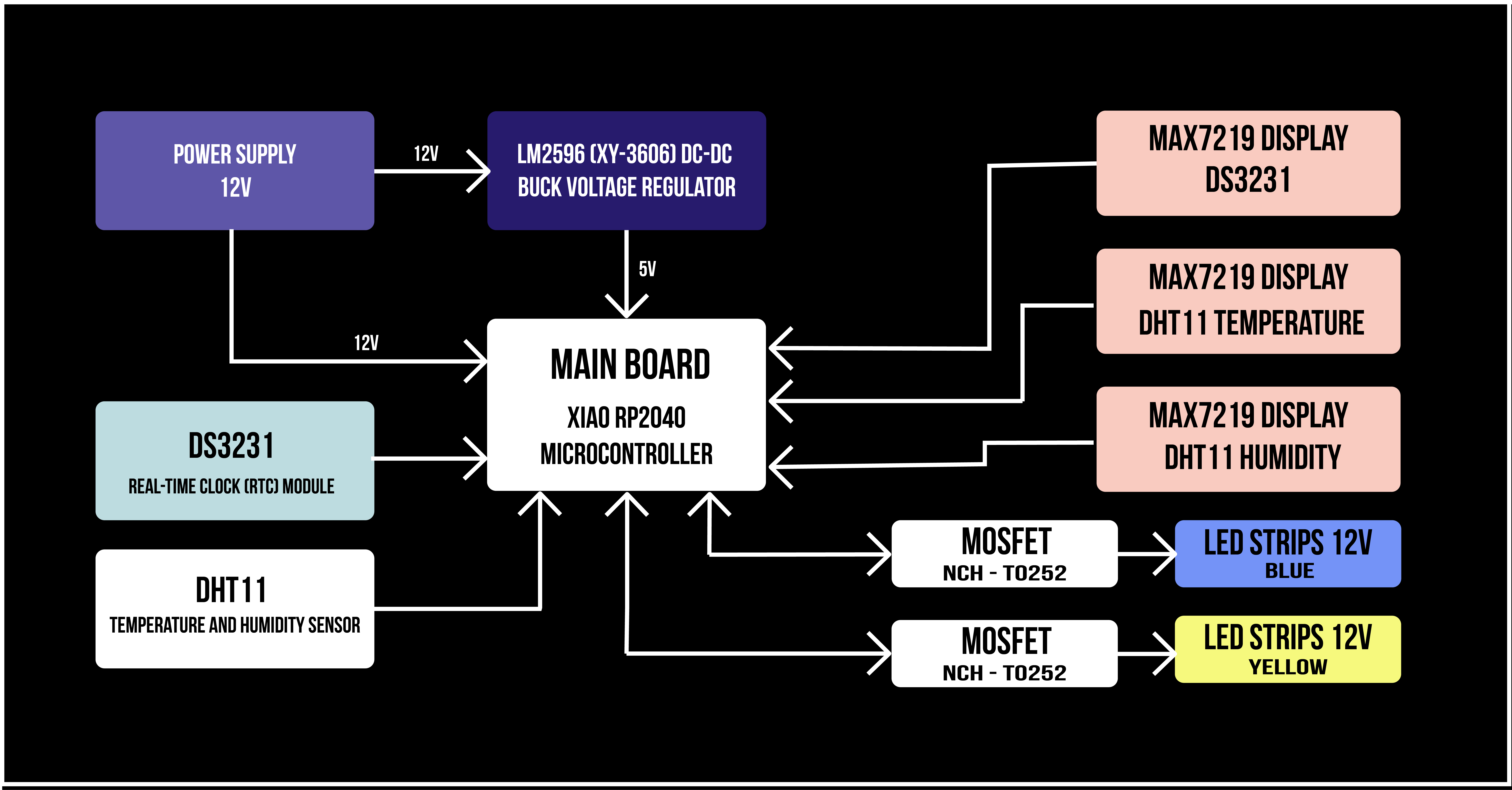
To present the structure of the electronic system and the connections between the modules, I created the circuit diagram and block diagram during Week 15.
The circuit diagram shows the connections between the main electronic components, including the XIAO RP2040 microcontroller, sensors, RTC module, LED matrix displays, LED strip control circuit, and power supply.
The block diagram provides an overview of the complete system architecture, showing the relationship between the power source, custom PCB, input devices, output devices, and the data flow within the system.
Wiring Setup
The connection between the external electronic modules and the custom PCB was implemented using jumper wires and separate power wires. Jumper wires were mainly used for connecting sensors, displays, and communication signals, making the testing and integration process easier during the development of the system.
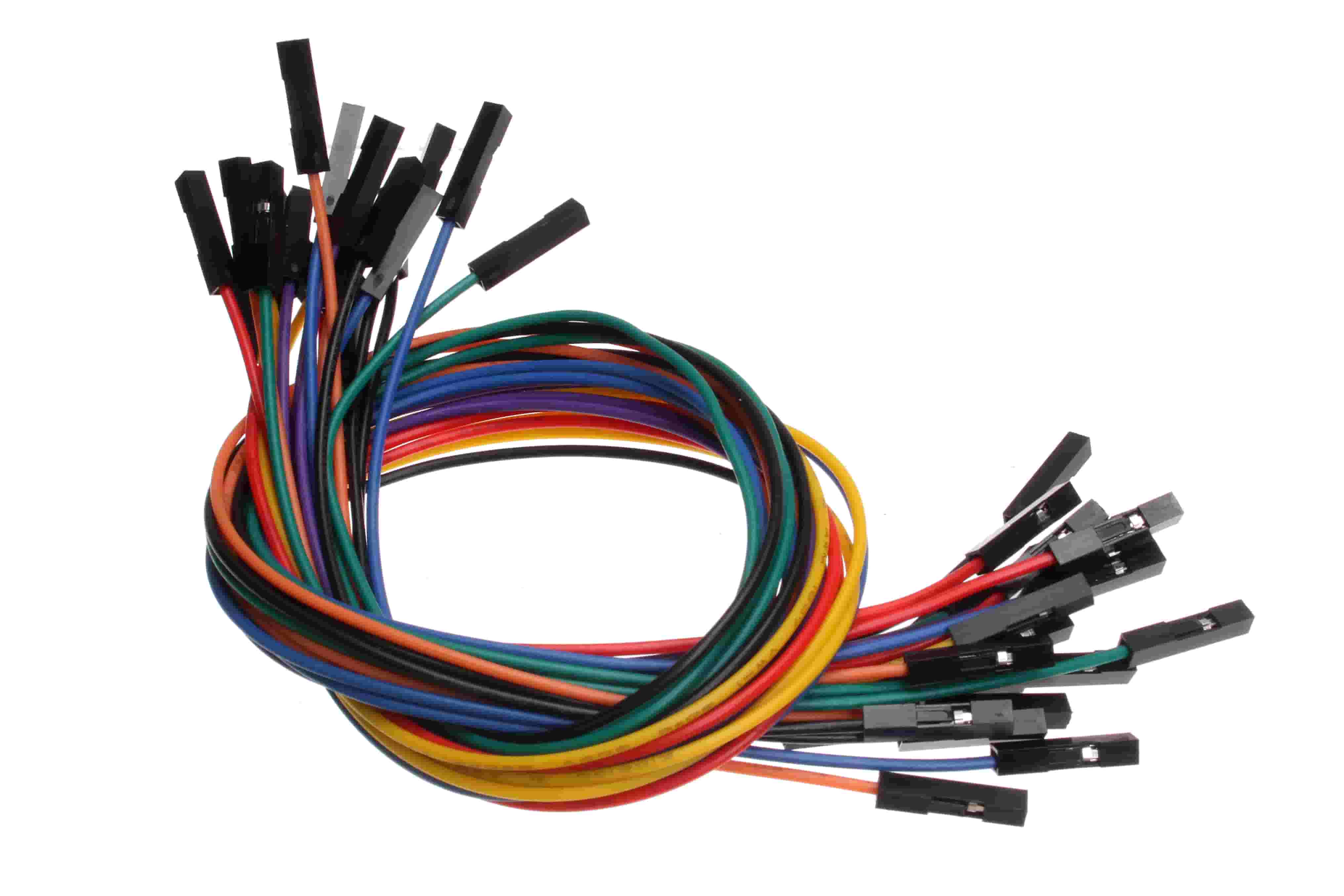
Image source: Wikimedia Commons – FF Jumper Wires

The LDR and DHT11 sensors, DS3231 RTC module, and MAX7219 LED matrix displays were connected using jumper wires to provide the required power and signal connections. At the same time, the 12V LED strip was connected using separate power wires, as it requires a higher current supply. The LED strip power line is connected to the 12V power source and controlled through the MOSFET driver circuit on the PCB.
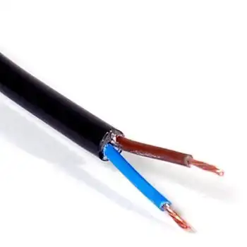
Image Source: IndiaMART – 2 Core Power Cable
The 5V power line is used for the XIAO RP2040 microcontroller and other low-voltage electronic modules, with the required voltage provided through the voltage regulation circuit.
Separating the signal connections from the power wiring helped to achieve a more reliable and organized electronic system.
Power System
The project is powered by an external 12V DC power supply, which provides the required energy for the operation of the complete system. The 12V output from the power supply is connected to the main PCB, where the power is distributed to the different parts of the system.
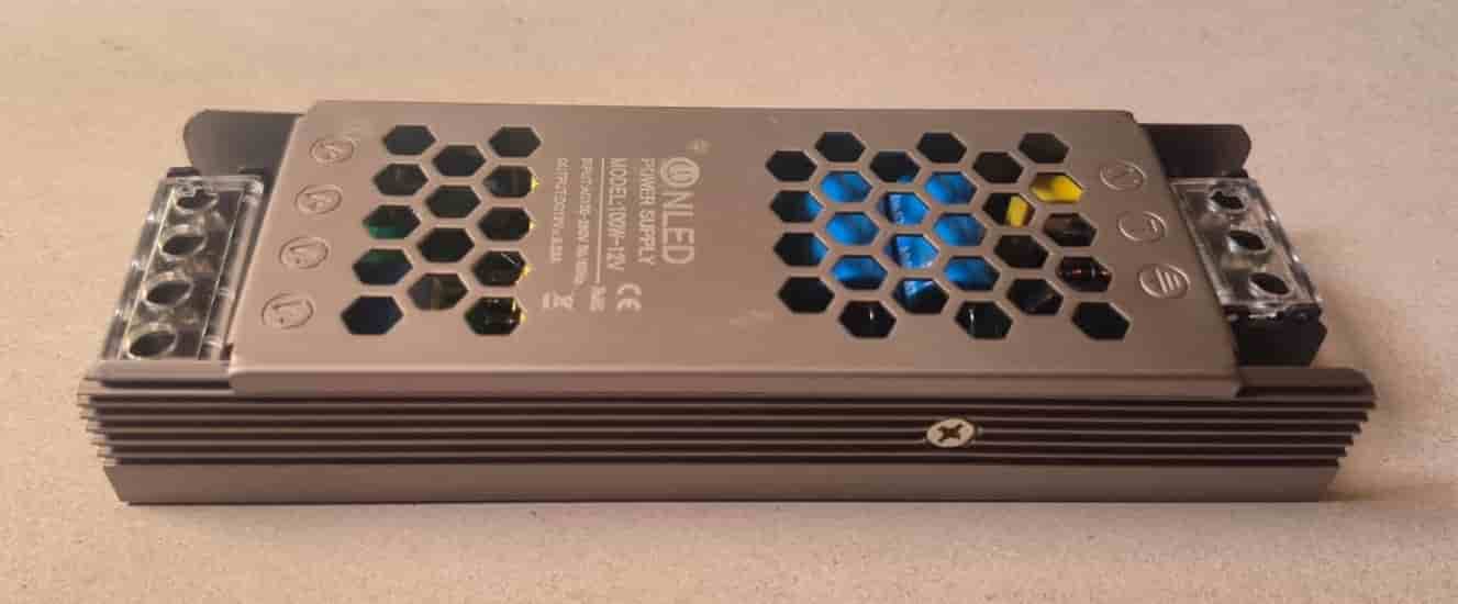
The 12V power line is routed through the PCB to the LED strip control section, where the LED strips are switched using the MOSFET driver circuit. Since the LED strips require a higher voltage and current, they are powered directly from the 12V supply line.
At the same time, the 12V input is converted to 5V using a voltage regulator, which is connected before the low-voltage power distribution. The regulated 5V output is supplied to the PCB and used to power the Seeed Studio XIAO RP2040 microcontroller and other low-voltage electronic modules, including the sensors, RTC module, and LED matrix displays.
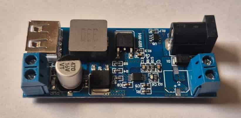
Separating the 12V lighting power line from the 5V control electronics helps ensure more stable and reliable operation of the system by reducing the influence of the higher current consumption of the LED strips on the sensitive electronic components.
Firmware
Some parts of the firmware and the initial testing of the electronic components were completed during Week 10 (Output Devices) as part of the weekly assignments. During the development of the final project, the code was significantly improved, reorganized, and expanded. The final version integrates all the sensors, displays, and lighting into a single program, creating a complete and reliable control system for the project.
The firmware was developed in Arduino IDE using C++ and runs on the Seeed Studio XIAO RP2040 microcontroller. Several libraries were used to simplify communication with the connected devices, including the MD_Parola and MD_MAX72XX libraries for the MAX7219 LED matrix displays, RTClib for the DS3231 Real-Time Clock, DHT for the temperature and humidity sensor, and Wire for I²C communication.
Firmware Source Code
The firmware continuously reads data from all connected sensors, processes the received information, updates the LED matrix displays, and controls the LED lighting automatically according to the ambient light level.
#include <MD_Parola.h>
#include <MD_MAX72XX.h>
#include <SPI.h>
#include <Wire.h>
#include "RTClib.h"
#include <DHT.h>


#define HARDWARE_TYPE MD_MAX72XX::FC16_HW


#define DATA_PIN 2
#define CLK_PIN 1


#define CS_RTC 29
#define CS_DHT 28


#define DHTPIN 27
#define DHTTYPE DHT11


#define MAX_DEVICES 4


#define LDR_PIN A0
#define LED1_PIN 9
#define LED2_PIN 10


int threshold = 500;

MD_Parola displayRTC(HARDWARE_TYPE, DATA_PIN, CLK_PIN, CS_RTC, MAX_DEVICES);
MD_Parola displayDHT(HARDWARE_TYPE, DATA_PIN, CLK_PIN, CS_DHT, MAX_DEVICES);

RTC_DS3231 rtc;
DHT dht(DHTPIN, DHTTYPE);

unsigned long lastDHTRead = 0;
unsigned long lastDisplayChange = 0;

float temperature = 0;
float humidity = 0;

bool showTemperature = true;

void setup() {
  Serial.begin(115200);

  Wire.begin();
  dht.begin();

  pinMode(LED1_PIN, OUTPUT);
  pinMode(LED2_PIN, OUTPUT);

  if (!rtc.begin()) {
    Serial.println("RTC not found!");
    while (1);
  }

  if (rtc.lostPower()) {
    rtc.adjust(DateTime(F(__DATE__), F(__TIME__)));
  }

  displayRTC.begin();
  displayDHT.begin();

  displayRTC.setIntensity(1);
  displayDHT.setIntensity(1);

  displayRTC.displayClear();
  displayDHT.displayClear();
}

void loop() {

  DateTime now = rtc.now();

  char timeBuf[10];
  sprintf(timeBuf, "%02d:%02d", now.hour(), now.minute());

  displayRTC.displayText(timeBuf, PA_CENTER, 0, 0, PA_PRINT, PA_NO_EFFECT);
  displayRTC.displayAnimate();


  if (millis() - lastDHTRead >= 2000) {

    lastDHTRead = millis();

    float t = dht.readTemperature();
    float h = dht.readHumidity();

    if (!isnan(t) && !isnan(h)) {
      temperature = t;
      humidity = h;
    }
  }

  if (millis() - lastDisplayChange >= 15000) {

    lastDisplayChange = millis();
    showTemperature = !showTemperature;
  }

  char dhtBuf[20];

  if (showTemperature) {
    sprintf(dhtBuf, "T %.0fC", temperature);
  }
  else {
    sprintf(dhtBuf, "H %d%%", (int)humidity);
  }

  displayDHT.displayText(dhtBuf, PA_CENTER, 0, 0, PA_PRINT, PA_NO_EFFECT);
  displayDHT.displayAnimate();

  int lightValue = analogRead(LDR_PIN);

  Serial.println(lightValue);

  if (lightValue > threshold) {
    digitalWrite(LED1_PIN, HIGH);
    digitalWrite(LED2_PIN, HIGH);
  }
  else {
    digitalWrite(LED1_PIN, LOW);
    digitalWrite(LED2_PIN, LOW);
  }
}
The program continuously reads data from the connected sensors and updates the outputs accordingly. The DS3231 Real-Time Clock (RTC) provides accurate time information, which is displayed on the first MAX7219 LED matrix. The DHT11 sensor measures the ambient temperature and humidity, and these values are shown on the second LED matrix, alternating every 15 seconds.
The LDR light sensor continuously monitors the surrounding light intensity. Based on a predefined threshold value, the microcontroller automatically controls the 12 V LED lighting through MOSFET transistors. When the ambient light level reaches the specified threshold, the LEDs are switched on automatically, and they are turned off again when the lighting conditions change. This behavior allows the installation to react autonomously to the surrounding environment without requiring any user interaction.
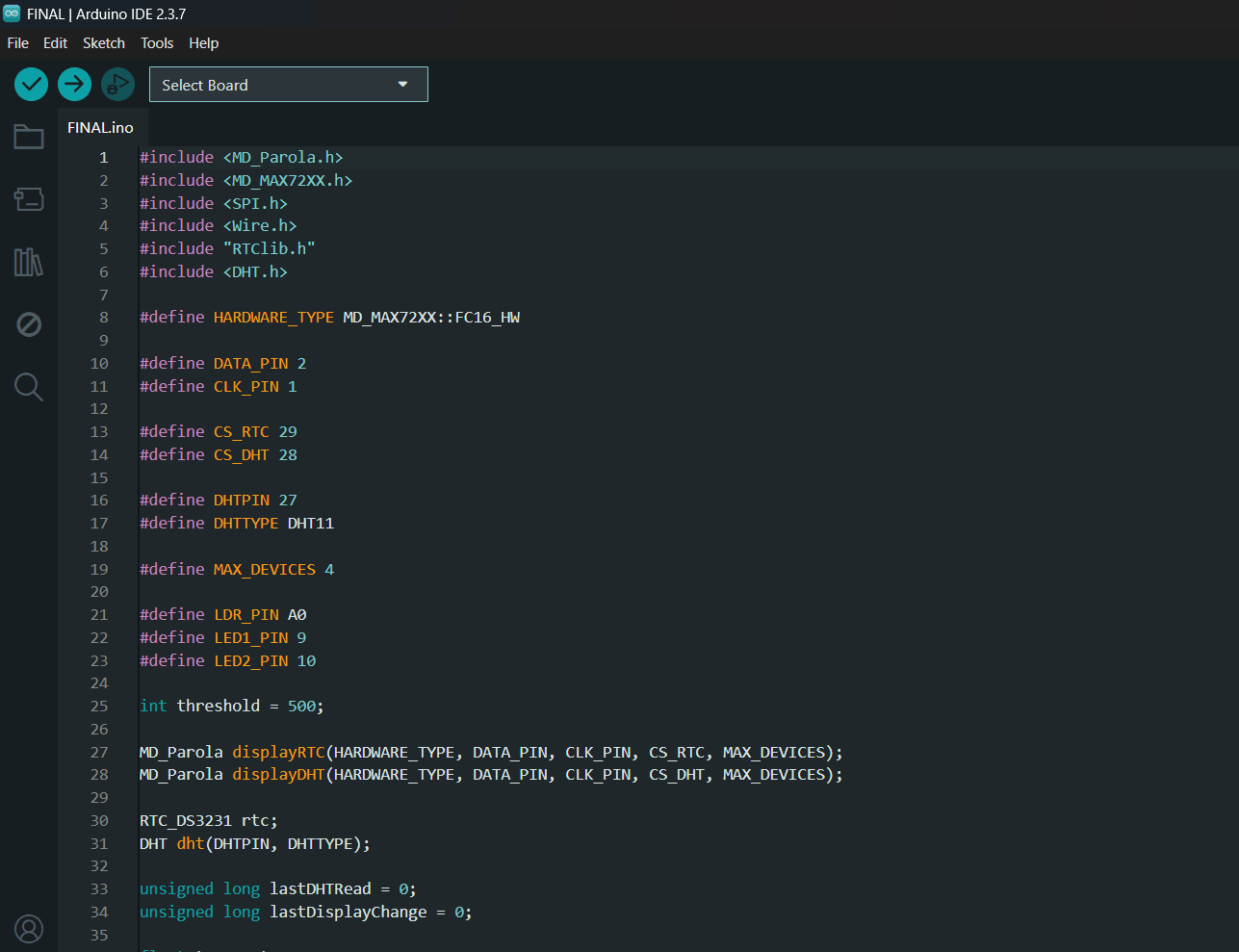
The firmware serves as the central control system of the project, integrating all input and output devices into a single application. It continuously monitors the surrounding environment, displays real-time information, and automatically controls the lighting, allowing the installation to operate autonomously without user intervention.
The complete Arduino source code is included in the project files together with the libraries required to compile and upload the firmware.
Enclosure and Final Design
During the final integration stage of the project, dedicated enclosures and mounting components were designed for all electronic modules to ensure secure installation, organized cable management, and convenient maintenance. All enclosures were designed in FreeCAD based on the actual dimensions of the corresponding components and fabricated using 3D printing.
Main PCB Enclosure
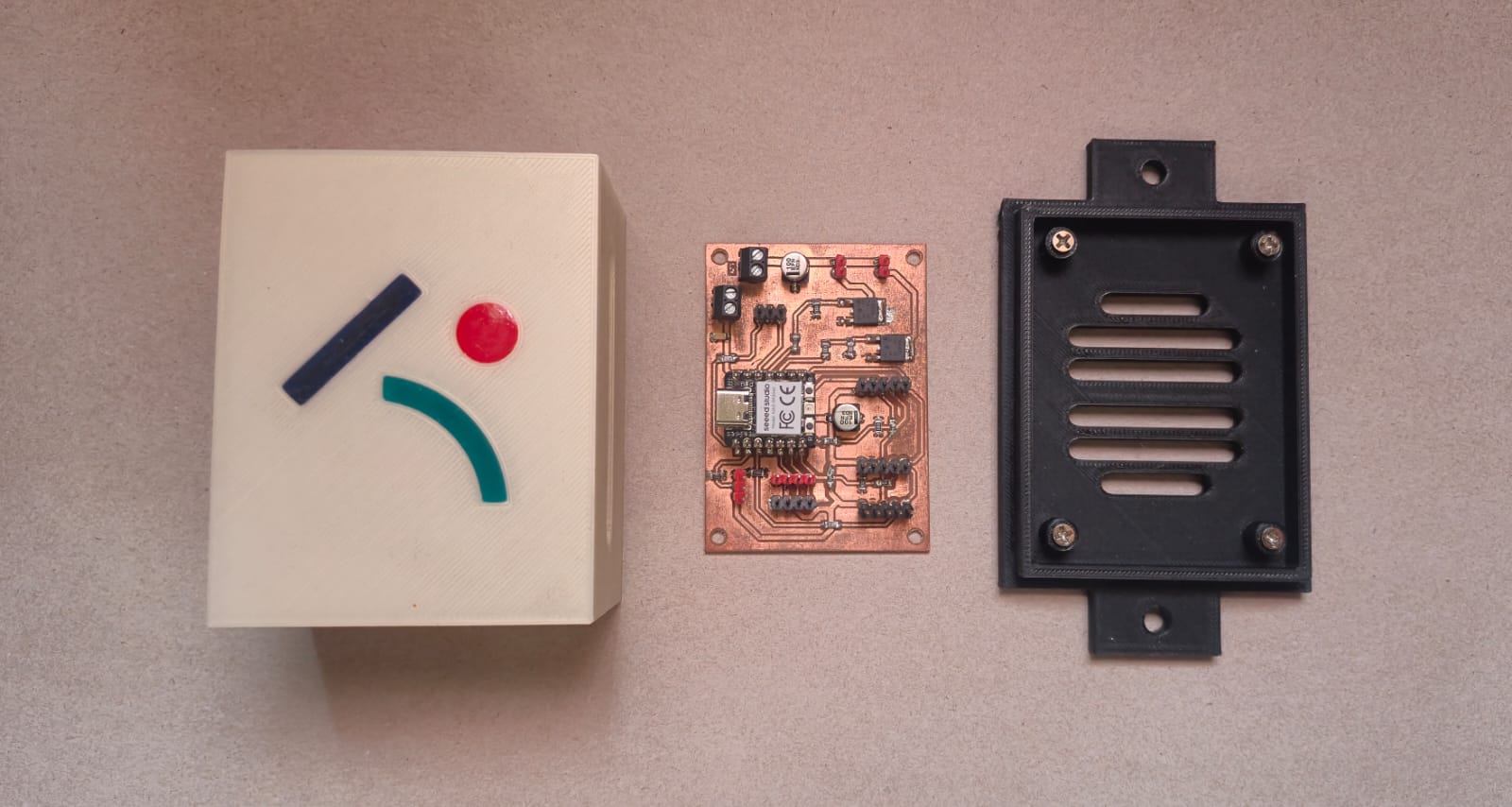
A dedicated enclosure was designed for the main PCB using the STEP model exported from KiCad. This approach ensured precise alignment of the mounting holes, connector positions, and overall board dimensions. The enclosure also includes ventilation openings and cable routing slots. The lid features the Fab Lab Armenia logo, which was filled with epoxy resin after printing to achieve a cleaner and more finished appearance.
Power Supply and Voltage Regulator Enclosures
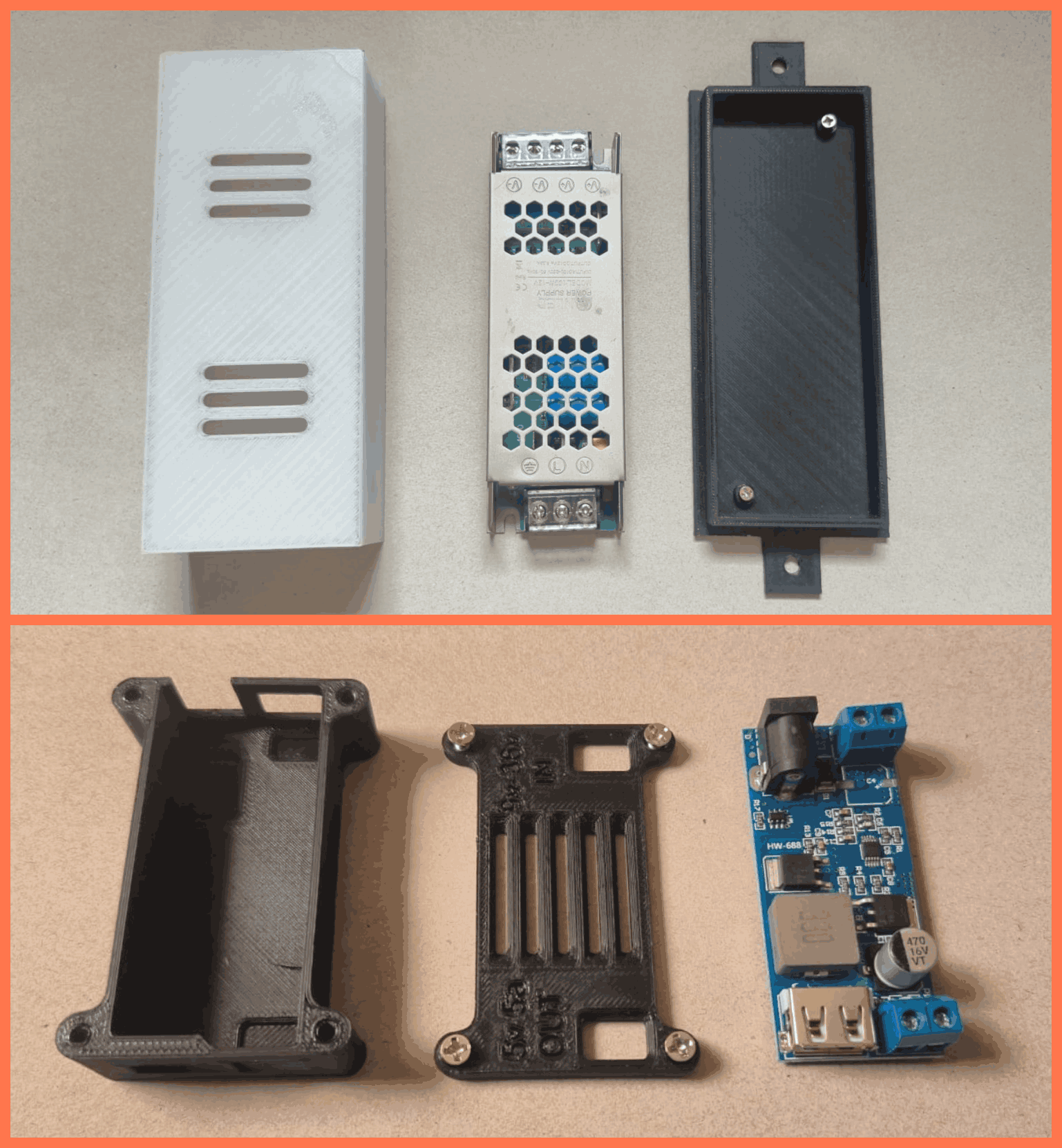
Separate enclosures were also designed for the 12 V power supply and the voltage regulator. Both enclosures were modeled according to the actual dimensions of their respective components, providing secure mounting and electrical isolation from the metal frame. Cable routing openings were also incorporated to simplify wire management and final assembly.
MAX7219 LED Matrix Mount
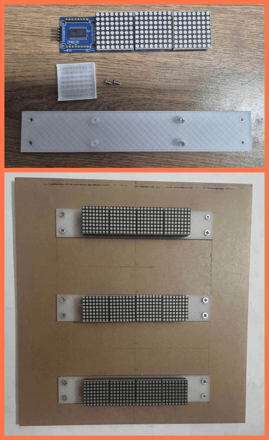
A dedicated mounting structure was designed for the MAX7219 LED matrices, allowing the three displays to be accurately positioned behind the mirrored acrylic panel. The mount maintains the correct spacing and alignment of the displays, ensuring that the information appears in the correct position and is clearly visible from the front after final assembly.
Final Assembly
After the enclosures were fabricated, the main PCB, power supply, and voltage regulator enclosures were mounted onto the acrylic base plate using bolts and nuts.

This mounting method provides a stable support structure, keeps the modules well organized, and allows the individual enclosures to be easily removed for maintenance or future modifications if necessary.
This section presents the final integrated structure of the project. The complete design, CAD modeling, 3D printing, and fabrication process for all enclosures is documented in the Week 15 – System Integration page.
Metal Structure Fabrication and Assembly
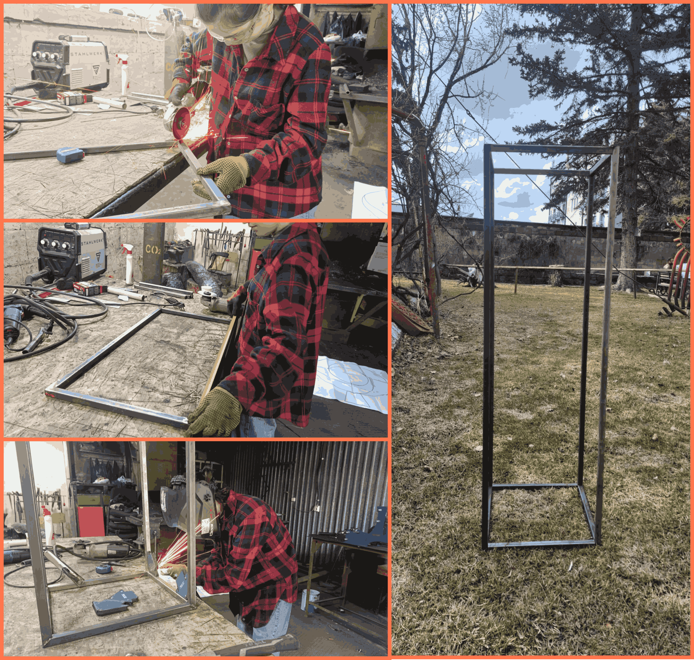
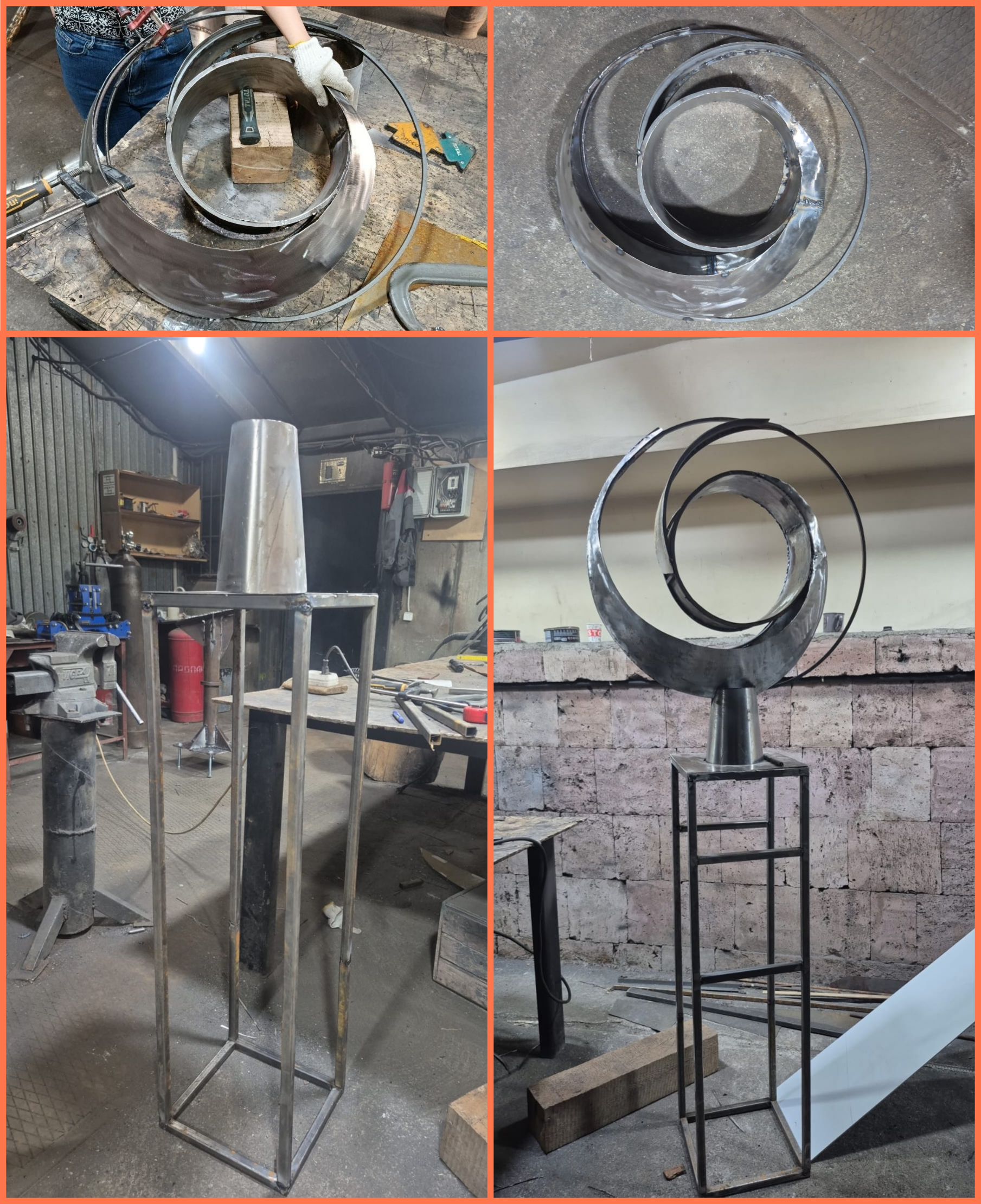
The main supporting frame of the project was fabricated from 20 × 20 mm square steel profiles, selected for their strength while remaining relatively lightweight. The metal profiles were cut to the required dimensions, aligned according to the design, and welded using a STAHLWERK IGBT welding machine. During fabrication, the geometry and alignment of the structure were periodically checked and adjusted when necessary to ensure accurate final assembly.
After completing the main frame, I fabricated the upper structure using 8 × 8 mm square steel profiles and 4 mm diameter round steel rods. The metal elements were cut to the required dimensions, shaped, and welded together to form the final geometry of the upper section.
The following video shows the cutting of the metal components used to fabricate the upper structure.
The following video shows the preparation and cleaning of the metal components before welding.
The following video shows the welding process used to assemble the upper structure.
To connect the upper structure to the main frame, I designed and fabricated a custom conical connector from sheet metal. The connector was manufactured by cutting and bending the sheet metal to the required shape, then welded to the main structure to provide a strong and stable connection between the upper and lower sections.
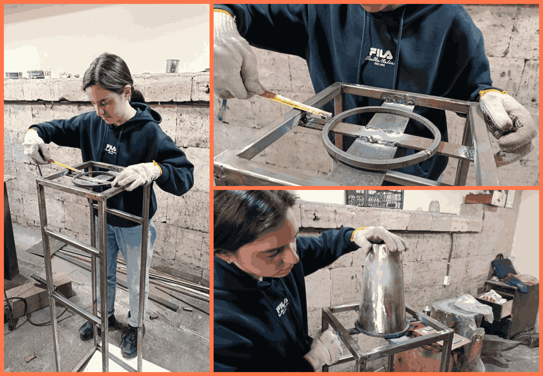
Additional metal supports for the conical section were also welded in place to ensure a stable and rigid connection between the upper structure and the main frame.

Once the welding process was completed, all joints and metal surfaces were finished using an INTERSKOL UShM-125/900 angle grinder to remove welding marks and surface irregularities, resulting in a clean and smooth finish.
Next, acrylic parts were fabricated according to the required dimensions. Since the structure included curved surfaces, the acrylic sheets were heated and shaped using a heat gun to match the geometry of the metal frame. A diffusion film was then applied to the acrylic surfaces to provide softer and more uniform LED light distribution.

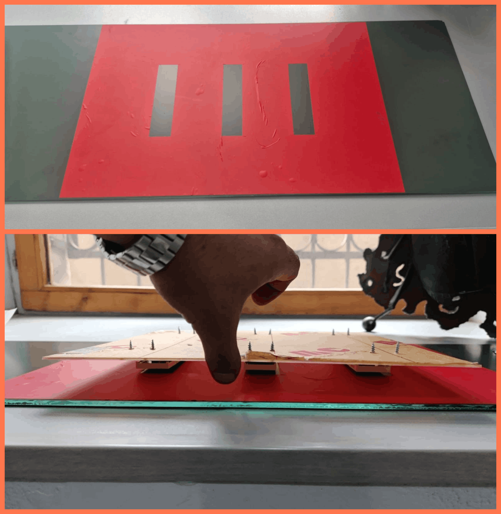
The next step was the preparation of the front mirror, behind which the displays would be installed. After determining the final positions of the displays, I designed their placement areas in 3D and prepared the corresponding sketch. Based on this design, I used a plotter cutter to create masking layers from Oracal film and applied them to the back side of the mirror so that only the required areas would be exposed during the sandblasting process.
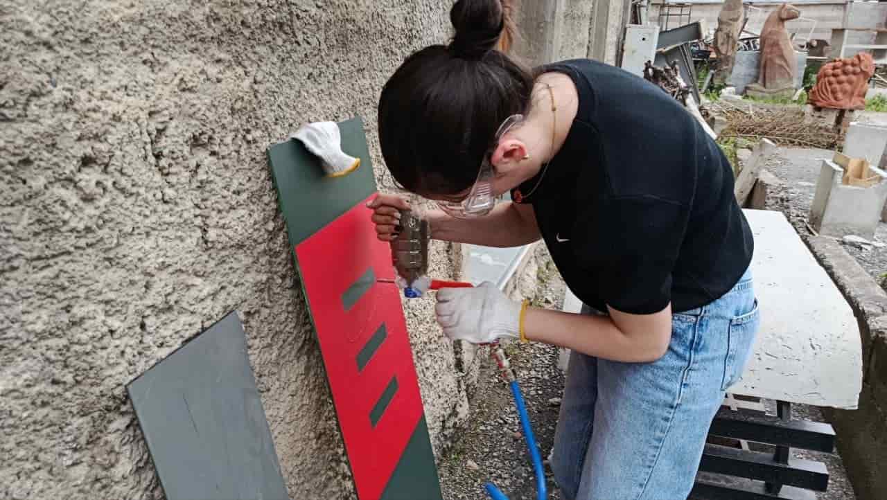
Together with Gevorg, we designed and fabricated a custom sandblasting attachment that allowed the abrasive flow to be directed precisely onto specific areas.
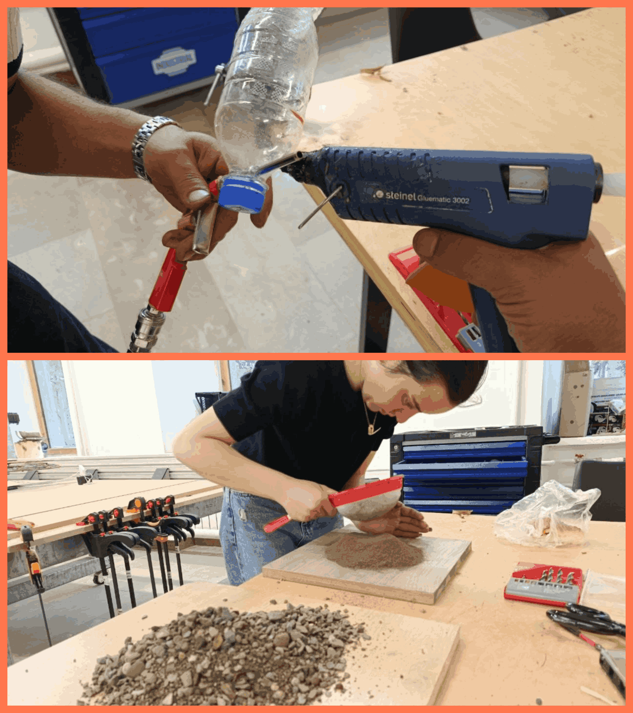
Using this tool, the protective coating on the back side of the mirror was removed only in the regions intended for the displays, creating transparent windows while preserving the remaining mirror surface.
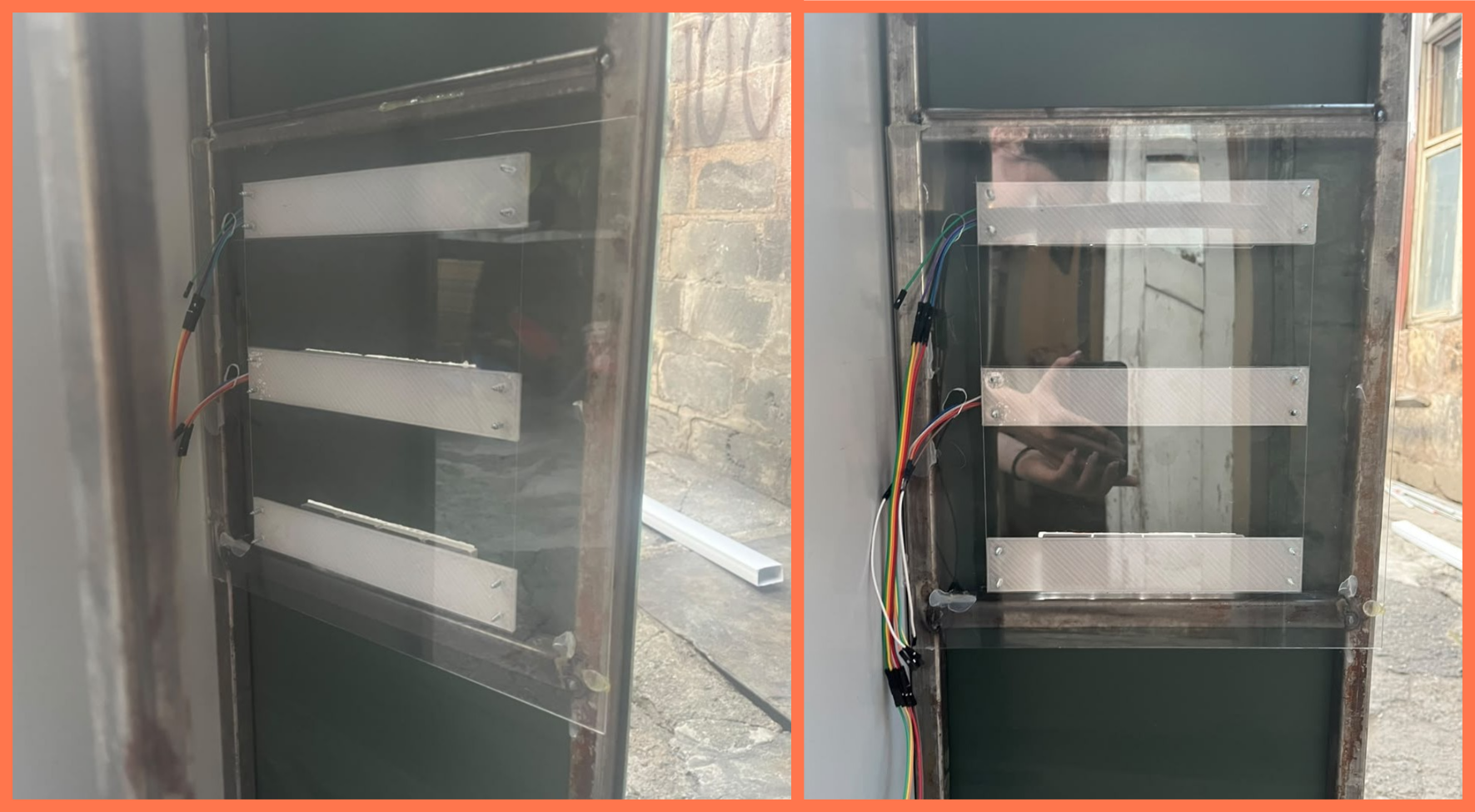
After the sandblasting process, the protective Oracal film was removed, and the mirror was fixed to the metal frame using silicone, ensuring a strong and even attachment. The rear acrylic panel, on which the displays had already been mounted, was then installed and secured with screws.
During the final assembly stage, after the main structural components had been connected, I installed the electronic components together with their custom-designed enclosures.
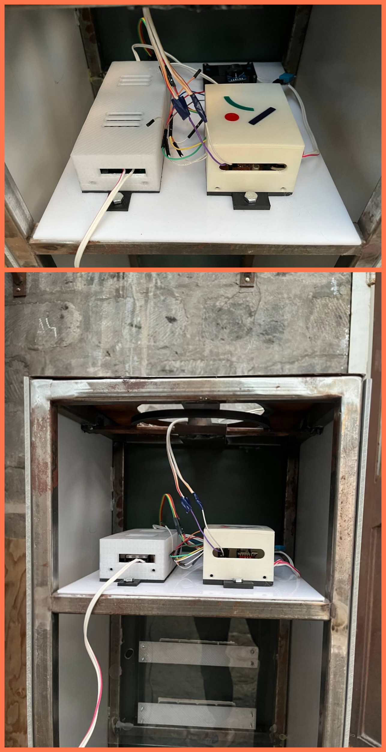
The main PCB, power supply, voltage regulator, and display modules were positioned and secured according to the planned system layout. After installing the electronic components, the LED strips were mounted, all electrical connections were completed, and after the final checks, the system was prepared for testing.
What Worked, What Didn’t
The electronic system was partially successful during the final integration process. The LDR sensor successfully detected changes in ambient light, and the automatic LED lighting control system responded appropriately to changes in lighting conditions. The DHT11 sensor and DS3231 RTC module were also successfully integrated into the system for measuring temperature and humidity and maintaining timekeeping functions, respectively.
However, the MAX7219 LED displays did not operate reliably in the final version of the project. Although they worked successfully during certain stages of development, their operation became unstable during the final integration process. Sometimes the displays showed only individual segments, sometimes they operated for a short period and then switched off, and in other cases they behaved unpredictably. To troubleshoot the problem, I checked the wiring connections, power supply, and DIN, CLK, and CS connections. I also reviewed the software and library configuration and tested the displays using another board. However, the problem continued, and the display functionality could not be fully completed in the final version of the project. I suspect that the MAX7219 modules may have had a hardware-related problem or a manufacturing defect. In the future, I plan to replace the modules with new ones and complete the display functionality.
The main challenges were also related to the mechanical fabrication of the metal structure. During assembly, several sections required additional welding, alignment corrections, and further adjustments to ensure that all components fit together properly. The curved acrylic elements also required several heating and forming attempts to achieve the desired shape. In the future, I plan to replace these acrylic elements with 3D-printed parts, which would allow for more precise control over their shape, dimensions, and structural fit.
Despite the limitations with the MAX7219 displays, the main interaction between the LDR sensor and the LED lighting system was successfully integrated and demonstrated in the final project video.
Final Project Bill of Materials (BOM)
| Qty | Description | Price | Link | Origin |
|---|---|---|---|---|
| 1 | MAX7219 display | 5 $ (~1,950 ֏) | temu.com | by in Temu |
| 1 | Voltage regulator | 3 $ (~1,170 ֏) | temu.com | by in Temu |
| 1 | 12V LED strip | 5 $ (~1,950 ֏) | - | Our Lab |
| 1 | DS3231 RTC module | 4–6 $ (~1,560–2,340 ֏) | temu.com | by in Temu |
| 1 | DHT11 sensor | 3 $ (~1,170 ֏) | temu.com | by in Temu |
| 1 | Photoresistor (LDR) | 2–3 $ (~780–1,170 ֏) | temu.com | by in Temu |
| 1 | Power supply | 7–8 $ (~2,730–3,120 ֏) | - | Our Lab |
| 1 | Wires and connectors | 2–3 $ (~780–1,170 ֏) | - | Our Lab |
| 1 | Metal sheet | 40 $ (~15,600 ֏) | Link | Our Lab |
| 1 | Mirror | 13 $ (~5,070 ֏) | Link | Our Lab |
| 1 m | Metal pipe | 1 $ (~390 ֏) | - | Our Lab |
| 1 m | Plastic film | 4 $ (~1,560 ֏) | - | Our Lab |
| 1 kg | PLA / PETG filament | 32.99 $ (~12,866 ֏) | prusa3d.com | Our Lab |
| 1 m² | Acrylic sheets | 18 $ (~7,020 ֏) | Link | Our Lab |
| - | XIAO RP2040 microcontroller | 6.23 $ (~2,430 ֏) | Seeed Studio – XIAO RP2040 | Our Lab |
| 1 | PCB boards | 9.05 $ (~3,530 ֏) | aliexpress.ru | Our Lab |
| - | MOSFETs, resistors, capacitors, and other electronic components | 3 $ (~1,170 ֏) | - | Our Lab |
| Total | ~165 $ (~64,350 ֏ AMD) |
Conclusion
ERKHOSUTYUN (Dialogue) is an interactive installation that automatically responds to environmental light conditions while displaying real-time information. The project integrates electronics, programming, digital fabrication, and metalworking into a single autonomous system, bringing together the skills developed throughout Fab Academy.
Files
License
ERKXOSUTYUN © 2026 by Ani Petrosyan is licensed under CC BY-NC-ND 4.0.
I have chosen the Creative Commons CC BY-NC-ND 4.0 license for this project after reviewing the available Creative Commons licenses.
This license allows others to copy and share the project, provided that proper credit is given to the original author. However, it does not allow commercial use, modification, or the creation of derivative works.
I selected this license to protect the originality and integrity of my project, preserve my copyright, and prevent unauthorized modifications or commercial use.