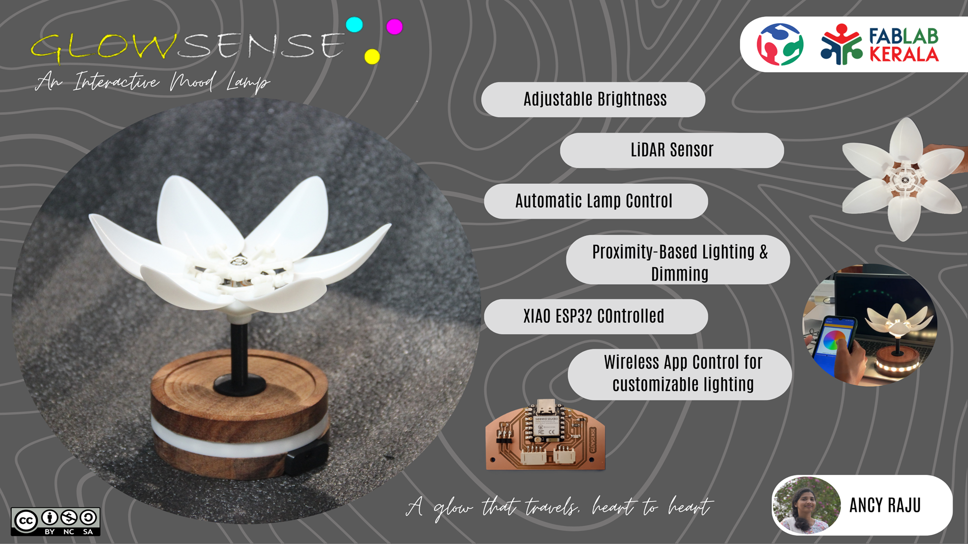
GLOWSENSE
GlowSense is an interactive flower lamp that glows and blooms in response to your presence.The closer you are, the brighter it glows. You can change its colors using an app.It's designed to save energy, look beautiful, and make your space feel calm and connected.
 >
>
Features
- Proximity based dimming
- Automatic lamp control
- Energy efficient
- Wireless app control for customizable lighting
- Interactive blooming petals
- Minimal and modular design
The Idea
For my final project, I originally proposed a proximity-sensing lamp using an ultrasonic distance sensor. The goal was to combine functionality with aesthetics-creating a lamp that not only looked beautiful but also promoted energy efficiency. My first design featured a dodecahedron shape, with delicate snowflake patterns cut into its faces to cast intricate light patterns. The idea was simple: when something came within a preset range, the lamp would begin to glow, increasing in brightness as the object got closer. As the course progressed, so did my ideas. During a peer review, Akash and Namita suggested incorporating movement, which opened up exciting possibilities for kinematic interaction. Later, our instructor Saheen encouraged me to consider wireless communication. These insights pushed me to evolve my design into something more interactive and emotionally engaging.
The final result is GlowSense-a blooming flower lamp that senses and responds to presence. Although I built only one lamp, the concept was envisioned with wireless interaction in mind. In a future version, one lamp could communicate with another—blooming and glowing in sync to create a sense of emotional connection between distant spaces. For details visit System Integration Page
To know about mechanism visit application and implications page
The rendered vs Actual Image
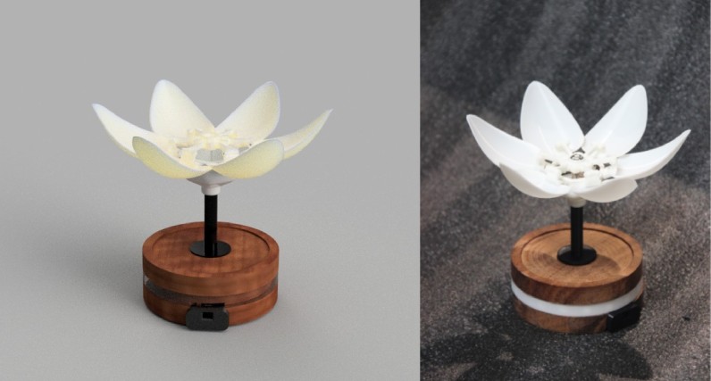
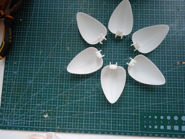
From the initial proposal, my project evolved significantly. One major change was the addition of kinematics the blooming motion of the petals was not part of the original concept but became central to the final design. I initially planned to use vacuum-formed petals, but after testing and refining, I switched to 3D printing for better precision and consistency. This change also allowed me to implement a petal-overlapping structure, which helped achieve a clean and elegant mechanical motion while maintaining the flower’s aesthetic. Despite these changes, I was able to closely match the final lamp to the original rendered design, both in form and function. The interactive behavior-responding to proximity with light and movement—worked as intended, and the visual design stayed true to the original concept.
Inspiration
 Everblooming mechanical tulip
Design

My design consists of :
ELECTRONICS

FUNCTIONALITY

Sources
For the development of my project, I referred to the Ever-Blooming Mechanical Tulip mechanism, which served as a primary inspiration for the blooming structure. I also explored previous Fab Academy project documentation and relevant YouTube tutorials to understand different design approaches and implementation techniques. For programming and code development, I utilized ChatGPT as a resource to generate and refine microcontroller code. Throughout the project, I received consistent guidance and feedback from my instructor, which was invaluable in overcoming technical challenges and shaping the final outcome.
Behind the Bloom: Making GlowSense
CAD in Fusion 360
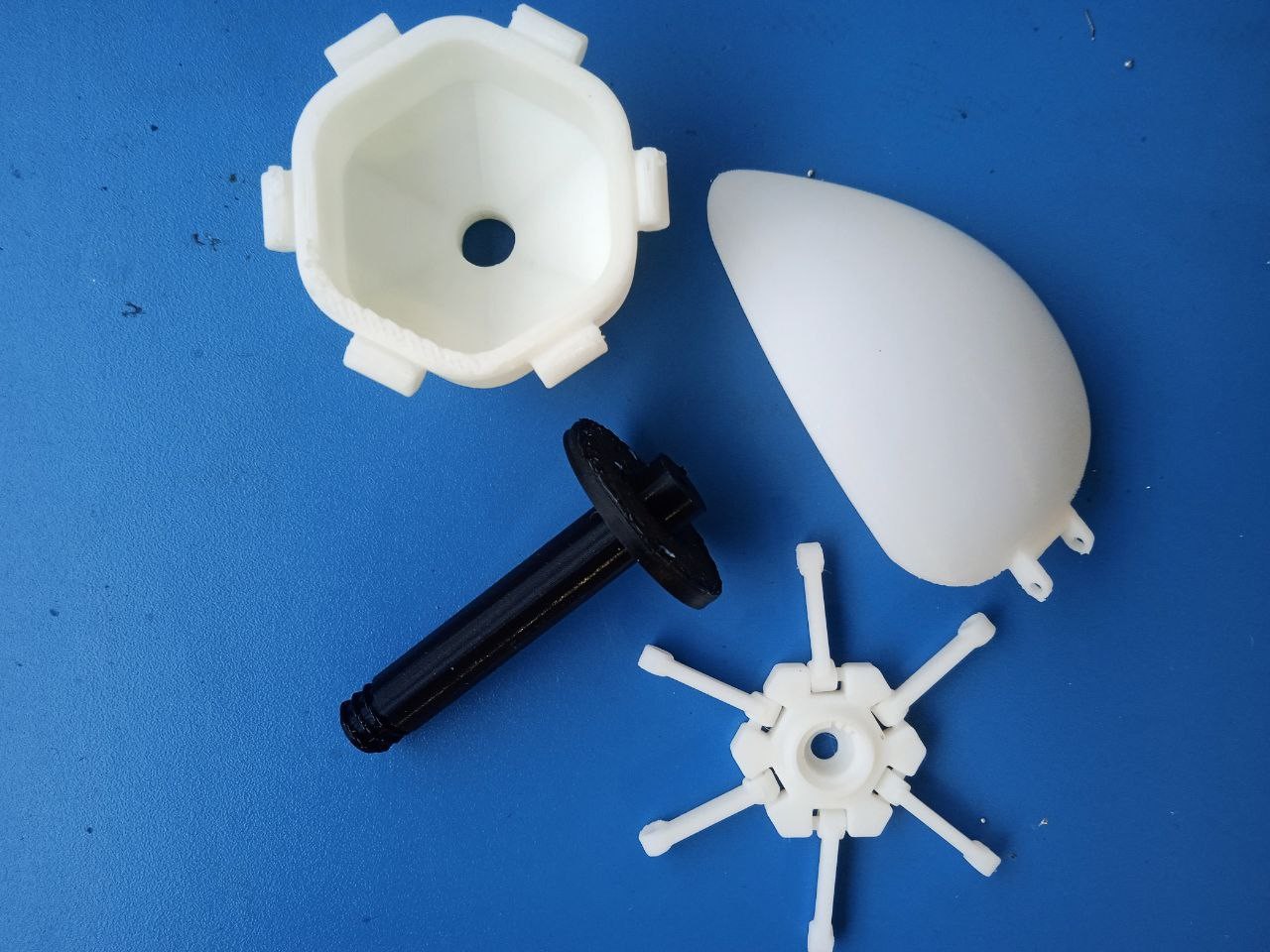
The CAD phase of GlowSense focused on designing and simulating the core mechanical components. I modeled the petals using splines and sweeps to create a natural, curved form, then segmented and shelled them for a lightweight, organic look. Pivot holes were added for linkage integration. To validate the blooming mechanism, I simulated the motion of the cup, shaft, and linkages in Fusion 360, refining linkage lengths and clearances for smooth actuation. I switched from vacuum forming to 3D printing for better control over shape and assembly.
I redesigned the petals, outer shaft, and cup as interrelated components. The stem was planned to press-fit into a wooden base, ensuring a stable foundation without the need for adhesives or fasteners. To support modularity, I incorporated a threaded joint between the stem and the cup. This allows the upper light assembly to be easily detached or replaced without affecting the base — ideal for future upgrades or repairs.
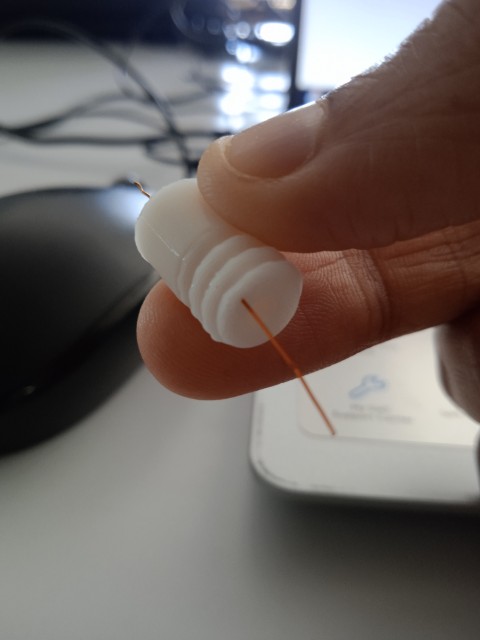
I also considered the electronics integration during the CAD phase. A dedicated space was included on top of the linkage to mount a NeoPixel, ensuring that the light would track the motion of the blooming petals.To maintain clean wire routing, I included 1 mm diameter holes in both the linkage and outer shaft. These act as channels for the Data In, 5 V, and GND wires, allowing them to pass neatly from the NeoPixel down to the base without interfering with mechanical movement.
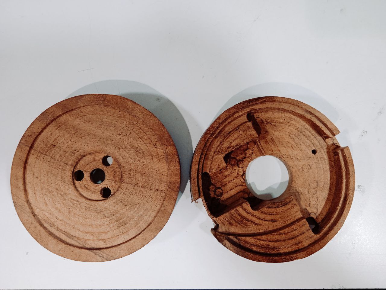
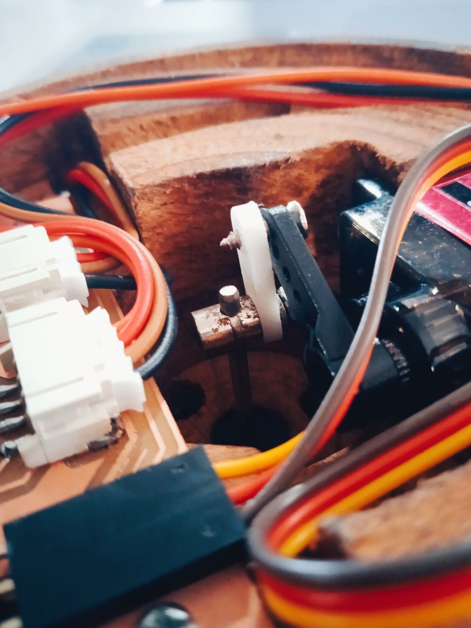
To neatly integrate the electronic and mechanical components, I focused on optimizing the wooden base. Following our instructor’s advice, the height of the base was adjusted to accommodate all internal components without crowding. A semicircular platform was created within the base to mount the PCB, with screw holes added to ensure a secure and stable fit. Just in front of this, a precisely dimensioned depression was carved to house the MG90S servo motor, keeping it firmly in place and aligned with the central axis of the mechanism. To organize the wiring, dedicated channels were modeled into the base to guide cables from the servo, NeoPixels, and distance sensor module down to the lower section — keeping the interior clean and free of entanglements.To maintain a clean appearance, I addressed the visible seam between the two stacked wooden base parts. Instead of leaving the joint exposed, I followed Saheen's suggestion and strategically placed a circular NeoPixel ring around the base at the point where the two layers meet.
PCB, servo and sensor all are neatly placed and attaced to the base firmly.
For more details, visit my project development page.
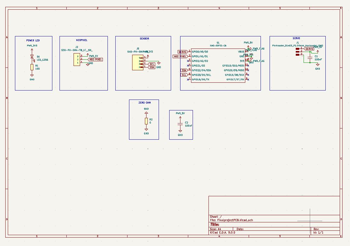
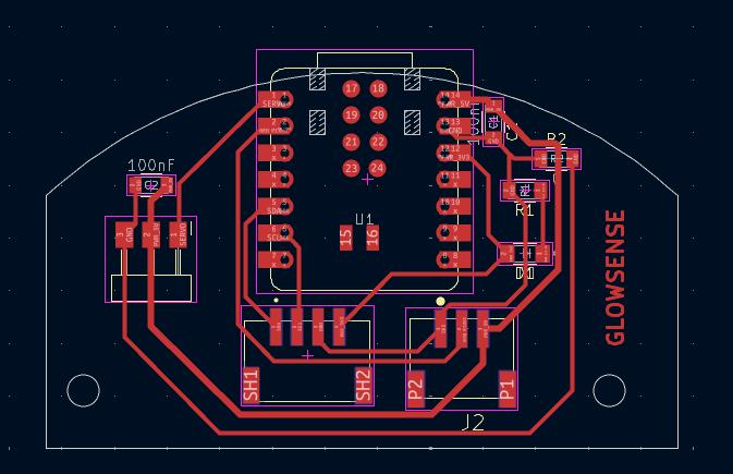
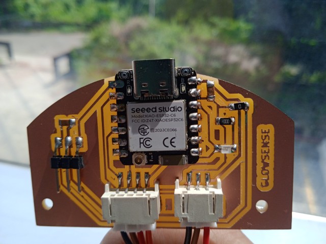
PCB
The custom PCB was designed in KiCad and built around the XIAO ESP32-C6 microcontroller, chosen for its compact size and built-in Wi-Fi support. A red power LED was added to the 3.3 V rail via a 100 Ω resistor to indicate board activity. The board includes a 4-pin horizontal JST connector for interfacing with a sensor module, with lines for VCC, GND, and I²C communication (SDA/SCL). A separate 3-pin JST connector supplies 3.3 V, GND, and data for controlling a NeoPixel LED. Additionally, a 3-pin header was provided for a servo motor connection, delivering VCC, GND, and a PWM signal. The layout was optimized for compactness and reliable connectivity within the limited internal space of the lamp base.
The board outline was created using an arc imported from Fusion 360, ensuring the edge cut matched the inner circumference of the project's base
The required components were requested through FabStash and collected from the Fab Inventory. After gathering all parts, I soldered them onto the custom PCB. The fully assembled board is shown below
For more details, visit my project development page.
Testing
Testing the Concept
Testing the concept using vaccum formed petals
Testing thread
Testing holes for copper wires
Testing the mechanism
3D printing the parts
All 3D-printed components including the petals, cup and pivot body were fabricated using PLA filament on the Bambu Lab A1 and A1 Mini printers.
 >
>
For more details, visit my project development page.
CNC milling
The wooden base was first cut to the target dimensions of 130 mm × 230 mm using a cutting machine to ensure it would fit within the working area of the TRAK CNC mill. The base’s thickness was then reduced from 30 mm to 20 mm using the TRAK for a sleeker profile and better component fit. Final contour cutting was performed on the Zund digital cutter. A DXF file exported from the CAD model was processed in Zund’s CAM software, where toolpaths were generated and optimized for the wood’s material and thickness. For more details, visit my project development page.
Mechanical Parts
Linkage-stopper
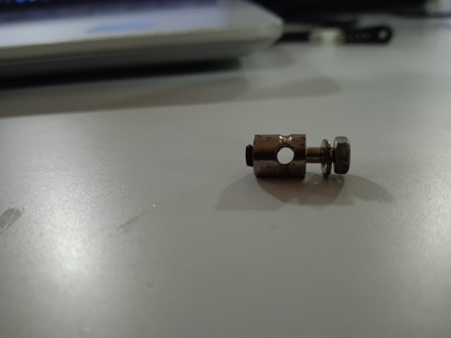
Linkage stoppers are used to connect the pushrod to the servo and control horn (or directly to the control surface). They allow for fine-tuning the length of the pushrod after it's been installed
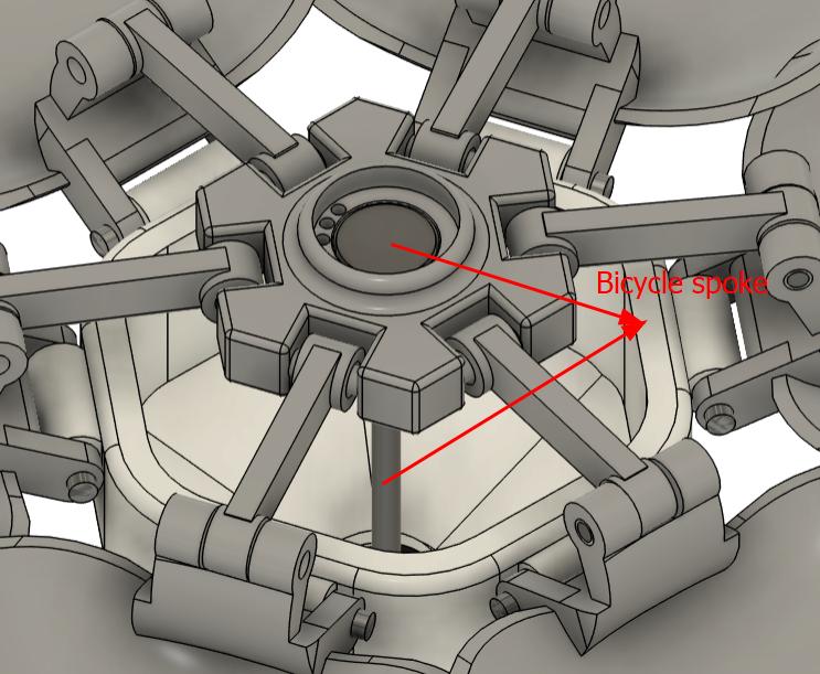
Bicycle spokes
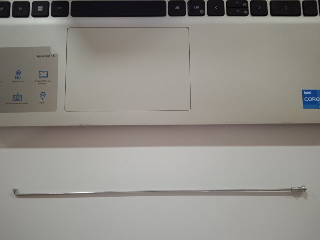
I used cycle spokes with a 2 mm diameter as pushrods for my linkage system. The spokes had threaded ends with caps, which I repurposed to attach the linkage. This setup made the connection between the pushrod and the linkage detachable, as they were joined through threading. Once I had adjusted the length to fit my mechanism, I simply cut off the excess spoke to keep everything neat and functional. This method gave me a strong, lightweight, and adjustable linkage without the need for specialized parts, and it worked reliably throughout the project.
Mechanical Jointing Using PLA Filament
To connect the linkages and petals in the assembly, small lengths of PLA filament were used as pins. These were inserted through aligned holes in the parts to act as mechanical fasteners. A soldering iron was then applied to both ends of each PLA pin, carefully melting and flattening them to form rivet-like heads. This technique effectively secured the parts together while maintaining rotational movement where required.
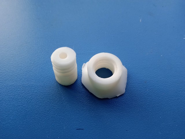
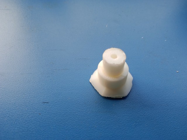
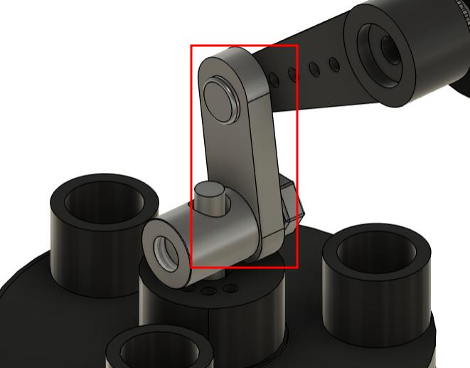
Pivot body
A pivot body was 3D printed to connect the servo horn to the linkage stopper. As the servo rotates, the pivot body compensates for the angular motion, ensuring smooth and controlled movement.The mechanism moves up and down, resulting in a smooth blooming and closing motion.
Assembly
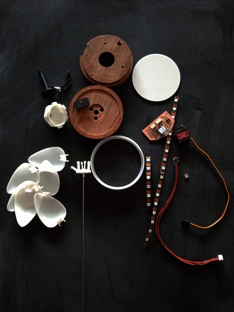
The assembly began with the petals, which were secured in place using PLA filament melted with a soldering iron. Once assembled, the petals were fixed into the cup. Next, the spoke head was attached, and a round NeoPixel was mounted onto the linkage. Three copper wires were routed through holes in the linkage and connected to the NeoPixel strip, which was fixed inside the cup. The linkages were then connected to the petals, and the wires from the strip were routed through the outer shaft down to the base. The inner shaft and outer shaft were joined using threaded connections. The assembled shaft was press-fit into the wooden base, and any excess length was trimmed. The three wires were then connected to the NeoPixel strip at the base junction, which was wrapped around with both the strip and the NeoPixel mount.
The second part of the base was screwed onto the first, securing all internal components. The NeoPixel strip and sensor were connected to the PCB using JST connectors. A small section of wood damaged during milling required the sensor mount to be glued in place. The servo motor was connected via a pin header and secured with screws, as was the PCB. Finally, a laser-cut acrylic plate was added to enclose the bottom of the base.For more details, visit my project development page.
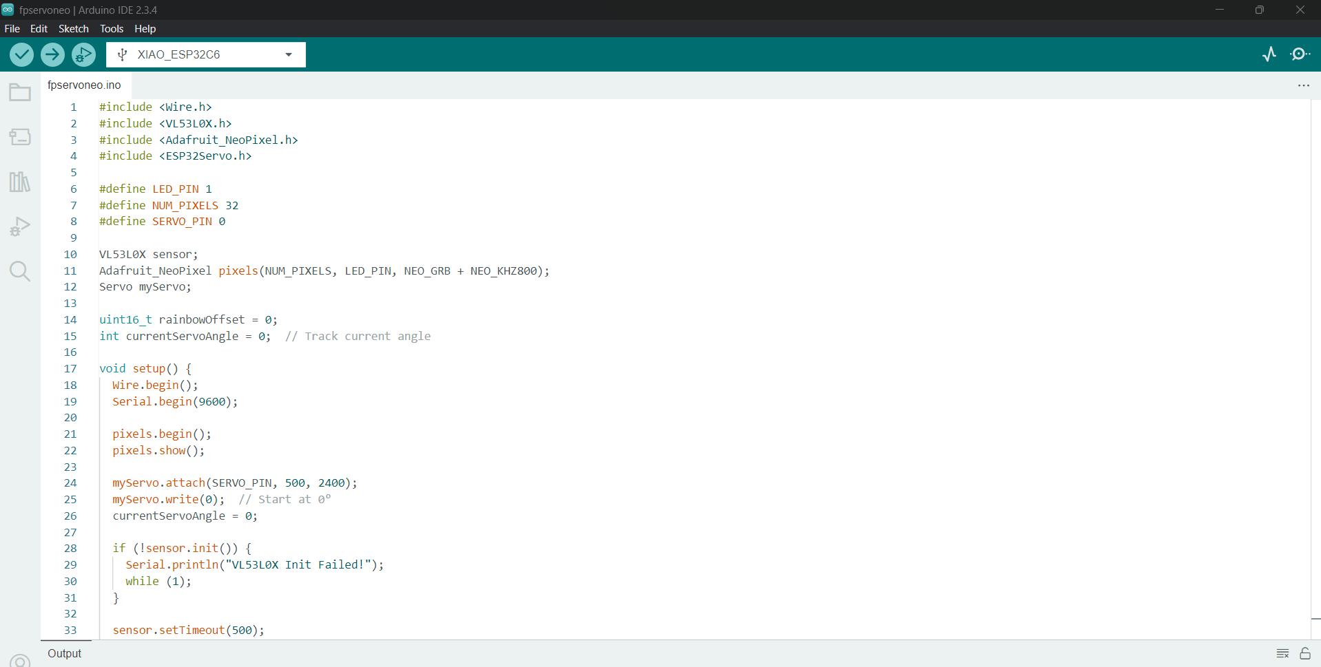
Programming
This code is for an interactive ESP32-based project that I developed with the help of ChatGPT. It combines a VL53L0X Time-of-Flight distance sensor, a NeoPixel LED strip, and a servo motor to create a responsive, animated light and motion display. The system measures distance in real time and reacts accordingly: when an object approaches within 15 cm, the servo motor smoothly opens a flower petal mechanism, and the NeoPixel LEDs display a dynamic rainbow pattern with brightness that increases as the object gets closer. When the object moves away, the servo closes the petals, and the LEDs turn off, creating an engaging and aesthetically pleasing interactive experience. For more details, visit my project development page.The complete program code is included in the files.
And just like that, the flower bloomed.
The complete program code is included in the files.
App integration
Kodular is a free, drag-and-drop platform that enables users to create Android applications without writing traditional code. It features a visual interface where users can design apps by assembling components like buttons, sensors, and layouts, and it employs a block-based programming system based on Google’s Blockly, similar to MIT App Inventor and Scratch.
As there wasn't any colour palette available, I had to create one. I searched in youtube and find a tutorial. I followed it to connect the blocks. The designer and blocks view are given below.


You can view the app and its development in the Interface and Application Programming week documentation.The complete program code is included in the files.
I were able to address many questions fromapplication and implications week
Through CAD simulation and real-world testing, I found that the MG90S servo motor provided enough torque to bloom the petals smoothly, aided by lightweight PLA linkages and bicycle spokes. Uniform blooming and reliable return were ensured by carefully designing symmetrical linkages with equal lengths and pivot points in Fusion 360. I used non-blocking Arduino code to coordinate the VL53L0X sensor, servo motor, and NeoPixels synchronously, enabling smooth, responsive behavior.In real-world use, the lamp reliably responded to hand proximity within 10–50 cm, with smooth light transitions and petal motion that offered a satisfying, emotionally expressive interaction.
The petal blooming mechanism, driven by a servo, functioned smoothly and reliably, while the NeoPixel brightness control based on distance sensing was both accurate and responsive. The modular design greatly simplified assembly and made troubleshooting easier. The custom PCB worked as intended, with clean routing and successful soldering, and the Kodular app enabled effective user interaction through color control. However, the initial plan to use vacuum-formed petals was abandoned due to unsatisfactory aesthetics and weak structure. The two-lamp wireless interaction feature was not implemented due to time and resource constraints, and a small section of the wooden base broke during milling, requiring a quick fix using glue.
In my final project, I successfully achieved all the primary success criteria. The lamp responded reliably to proximity using the VL53L0X time-of-flight sensor, smoothly adjusting the NeoPixel brightness to reflect distance changes, which was the core interactive feature. I also implemented a functional blooming mechanism—using a servo motor, the petals opened and closed in sync with proximity detection, adding a dynamic and expressive element to the interaction. I completed a fully integrated single lamp that combined responsive lighting, blooming petals, distance sensing, and app control through Kodular, all while maintaining clean mechanical and electrical integration. Although I wasn’t able to finish the second lamp, I designed the system to be modular and scalable.While the wireless communication between lamps wasn’t implemented in the final prototype, I documented the concept thoroughly, and the system was technically prepared to support it, showing progress toward this extended goal.
The GlowSense project shows how sensor-based interaction can be used to create emotionally engaging, functional designs. It successfully combines proximity sensing, lighting, and motion in a compact, modular system using low-cost hardware. The wireless-ready architecture makes it scalable, paving the way for future development of multi-lamp communication and synchronized behavior. By merging engineering with artistic expression, the project highlights the potential for smart, interactive devices in ambient lighting, wellness, and educational contexts.
Future Plans
The lamp is powered by an ESP32-C6 microcontroller, which supports Wi-Fi connectivity. Building on this capability, I plan to create a second flower-shaped lamp and demonstrate how the two lamps can communicate wirelessly. Using the built-in Wi-Fi, the lamps will exchange data—for example, when someone approaches one lamp, the second lamp will respond by mimicking the blooming motion and LED animation. This interaction will showcase wireless synchronization between devices, allowing them to react to shared inputs in real time. It transforms the lamps from standalone objects into a connected, interactive system.
BOM
| Item | Quantity | Unit Cost (₹) | Total Cost (₹) | Supplier | |
|---|---|---|---|---|---|
| Servo motor | 1 | 149.0 | 149 | Fab Inventory | link |
| Xiao esp32 C6 | 1 | 555.0 | 555 | Fab Inventory | link |
| Neopixel strip | 24 no | 120.0 | 120 | Fab Inventory | link |
| VL53L0X Sensor | 1 | 176.0 | 176 | Fab Inventory | link |
| Capacitor 100NF / 0.1uf 50 v | 2 | 1.0 | 2 | Fab Inventory | link |
| Resistor 0 ohm | 1 | 1.0 | 1 | Fab Inventory | link |
| Resistor 100 ohm | 1 | 1.0 | 1 | Fab Inventory | link |
| JST 4 pin male connector | 1 | 1.0 | 1 | Fab Inventory | link |
| JST 3 pin male connector | 1 | 1.0 | 1 | Fab Inventory | link |
| LED red | 1 | 1.0 | 1 | Fab Inventory | link |
| Wood | 130*230 mm | 60 | 60 | Locally sourced | link |
| Cycle spokes | 1 | 4 | 4 | Locally sourced | link |
| Linkage Stopper | 1 | 18 | 18 | Locally sourced | link |
| PLA filament | Fab Inventory | ||||
| Acrylic | Fab Inventory | ||||
| Total cost = 1089 |
Files
CADfilesKiCADfiles
Program files
Logo