Week 4: Embedded Programming

*Morse code input decoder.
Group Assignment
We began with a simple introdution to programming languages, which are most compatible and favorable for embedded programming. Then we continued with the most comman prcoessor families, and as examples looked into a couple of microcontroller units [or MCUs] and microprocessors.
Onik, our local instructor, gave us each an Arduino UNO, an LCD, a breadboard, and jumper wires. He specifically mentioned that we could use any tool we’d like, whether that’s an AI, textbooks, datasheets… anything, just to solve it ourselves. But there was a catch!
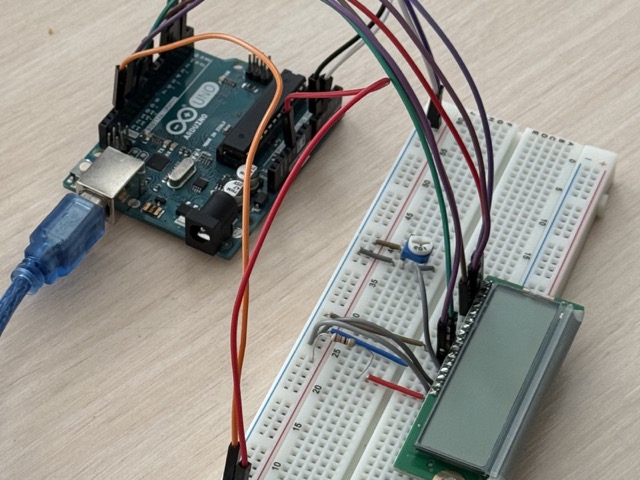
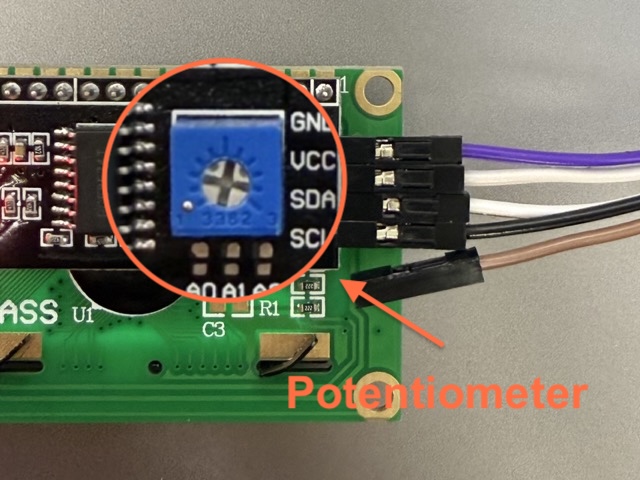
After hours and hours of search, us convincing AI tools that we need no potentiometers, and that the given set of items was enough we gave up. After that we found out that we either needed an LCD screen with an attached potentiometer, or we should have used more jumper wires and rigged the setup with a potentiometer.
C++
#include <Wire.h>
#include <LiquidCrystal_I2C.h>
LiquidCrystal_I2C lcd(0x27, 16, 2);
// sets the I2C address for the columns and rows
void setup() {
lcd.init();
// starts the display
lcd.backLight();
// turns on the screen light
lcd.setCursor(0,0);
// moves cursor to top-left
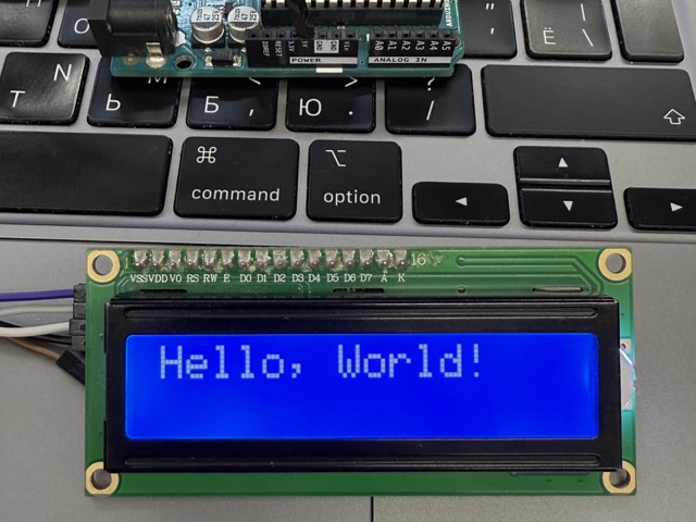
lcd.print("Hello, World!");
// displays the text
}
void loop() {
// Nothing else needed
}
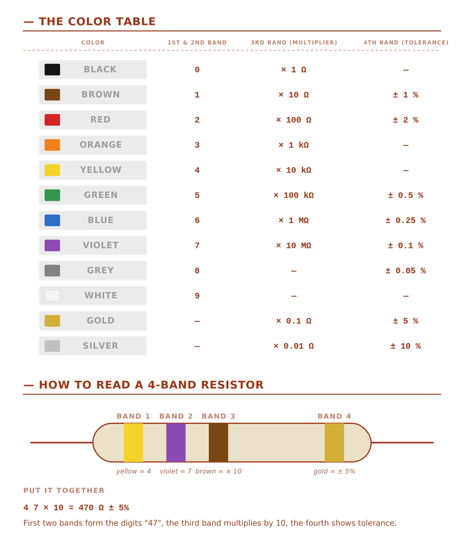
Resistors
Resistors control the flow of electricity in a circuit to prevent components from getting too much power. Without them, sensitive parts like LEDs would pull in too much current and instantly burn out or break.
Because different components need different levels of electrical current, resistors come in various resistance. This resistance is measured in Ohms, denoted by the capital Greek letter omega [Ω]. The resistors have color bands around it, which help us identify its resistance ammount. Refere to the color table below.
 *Prompt4.1
Tinkercad
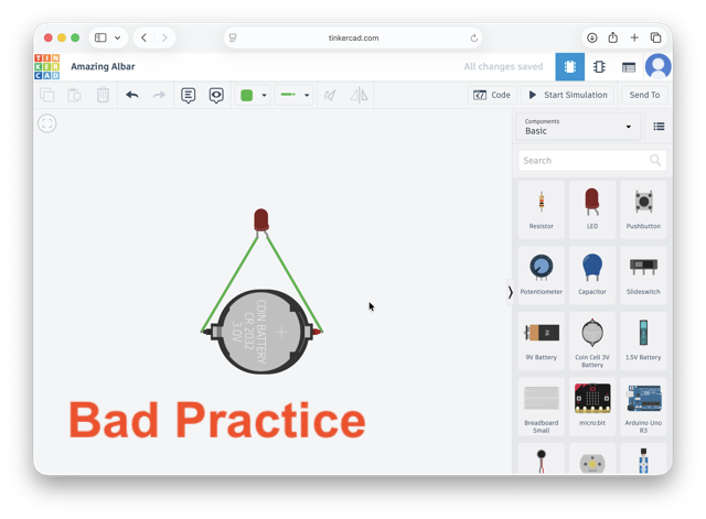
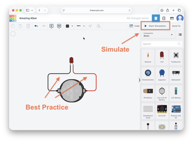
![]() Tinkercad Circuits is like a digital LEGO set for electronics, where you just drag, drop, and snap components together. It completely removes the fear of getting zapped or frying expensive parts because everything lives safely on your screen. If you make a wiring mistake, the worst that happens is a cartoonish graphics with no real-world damage.
Tinkercad Circuits is like a digital LEGO set for electronics, where you just drag, drop, and snap components together. It completely removes the fear of getting zapped or frying expensive parts because everything lives safely on your screen. If you make a wiring mistake, the worst that happens is a cartoonish graphics with no real-world damage.
Useful fact: Tinkercad is part of AutoDesk, which also owns Fusion 360, and means that it is not limited to circuts only. This also means if you end up using Tinkercad’s CAD software you can transfer the designs onto Fusion 360 for more complex manipulations.
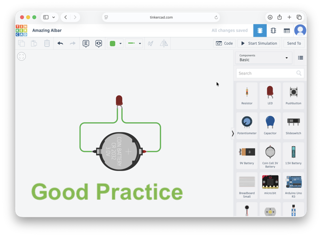
The same can be achieve using an Arduino UNO as the power source, or can be plugged onto a breadboard still using the development board as power source.
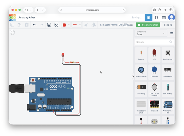
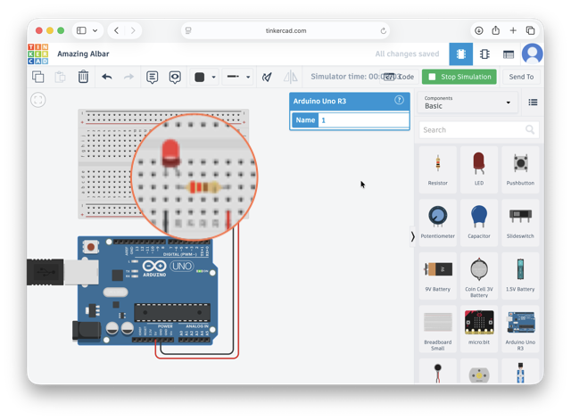
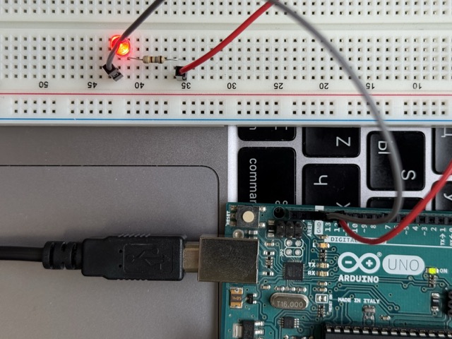
You can use Tinkercad for coding purposes too, but as I am simulating a simple LED with no specific command, the Ardunio UNO is used solely for the purpose of a power. The same is implemented in the image below, recreating the same setup in real life.
Arduino
Arduino is an open-source hardware and software company that designs and manufactures programmable circuit boards and developer tools. They act as an all-in-one ecosystem, providing both the physical microcontrollers and the environment to program them.
You might recognize Ardunio by their flagship microcontrollers Arduino UNO, it is actually quite old technology today. Because Arduino is completely open-source, other brands freely use their blueprints to manufacture nearly identical, cheaper clone boards, as well as highly upgraded versions with built-in Wi-Fi and faster processors.
Arduino IDE
![]() Arduino IDE [Integrated Development Environment] is an application, or simply put – a code editor, where you write, compile, and upload the code onto your microprocessor. The IDE primarily uses C++, though it also fully supports standard C, though it uses a simplified custom wrapper around C/C++ to make coding easier [for beginners].
Arduino IDE [Integrated Development Environment] is an application, or simply put – a code editor, where you write, compile, and upload the code onto your microprocessor. The IDE primarily uses C++, though it also fully supports standard C, though it uses a simplified custom wrapper around C/C++ to make coding easier [for beginners].
When you first open the application, the IDE greets you with a default code structure:
C++

void setup() {
  // put your setup code here, to run once:
}

void loop() {
  // put your main code here, to run repeatedly:
}
setup() function runs exactly once when the Arduino powers on or resets. It is used to initialize variables, pin modes, and libraries before the main code starts
loop() function runs continuously in an endless cycle immediately after the setup() function finishes, it contains the main logic of your project, such as reading sensors and controlling outputs
return type tells the computer whether that answer will be a number, a word, or nothing at all, in this case void is the return type – returns nothing
Serial Plotter [Graph Icon]: graphically plots incoming numerical data in real-time,useful for visualizing changing sensor data, like wave patterns or acceleration.
Individual Assignment
RP2040
For me, all the procesor families seemed to be quite intimidating. ATiny, ARM, STM, AVR… followed by numbers only make it more complicated from the first glance. While I have heard of these before, I never really dedicated time to understand if there’s some grouping or logic behind them. I did not know if these names also included producer names, or just a series of chips… So here’s a break down on the example of XIAO RP2040.
So, first off the word “xiao” is the Chinese word for “tiny.” Second off, it is the official product line name created by Seeed Studio.
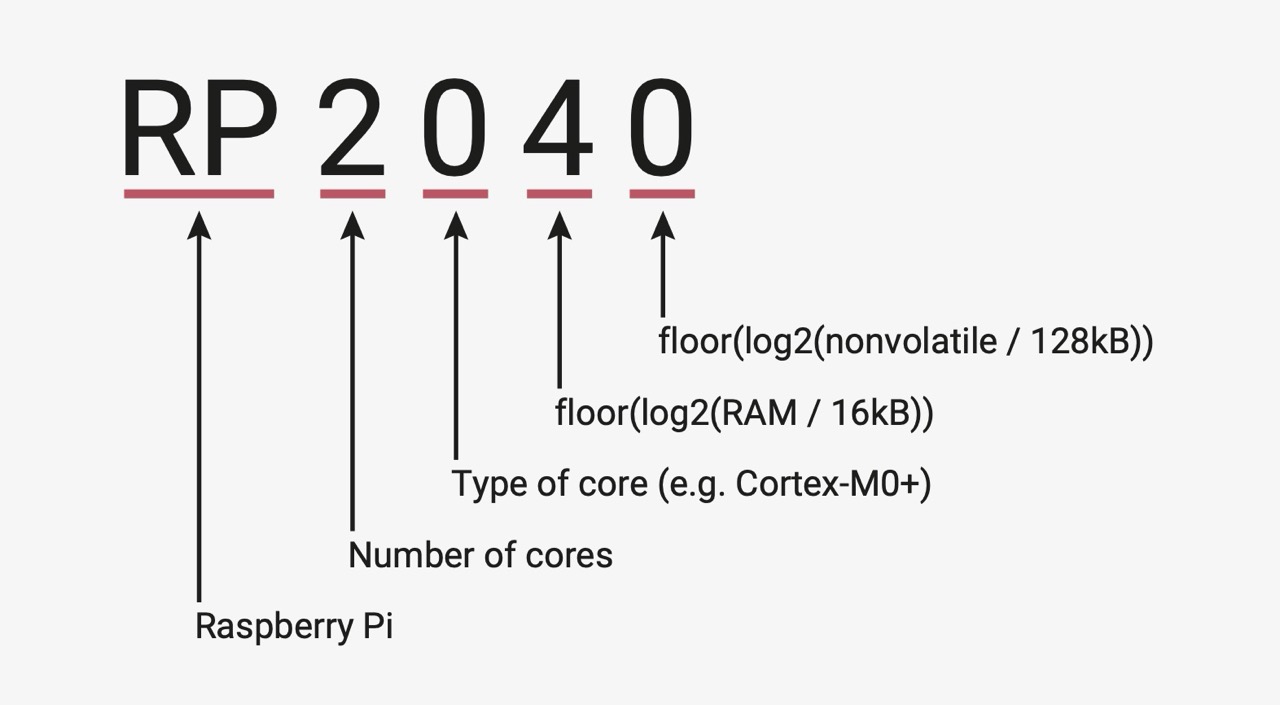
So, the XIAO RP2040 has the Raspberry Pi microcontroller powering it. It packs two processor cores, Raspberry Pi’s official naming convention decodes RP2040 as a Raspberry Pi chip with 2 ARM Cortex-M0+ cores, 0 (M0+) processor type, 4 (264 KB) of RAM, and 0 internal flash storage.
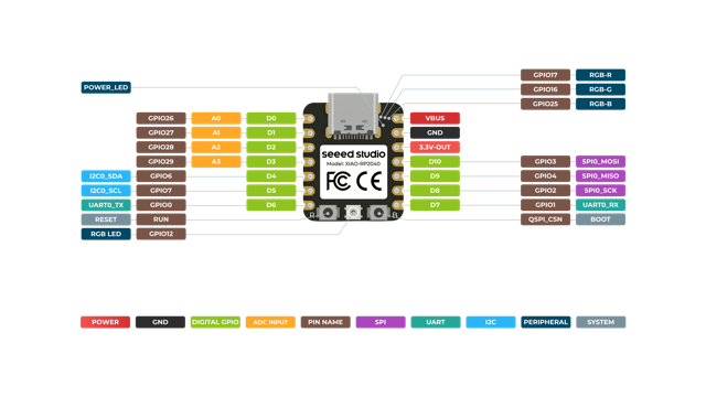
The Hardware: features a dual-core ARM Cortex-M0+ processor running up to 133 MHz alongside 264KB of SRAM [Static Random-Access Memory] and 2MB of flash storage. For connectivity, it packs 11 digital pins, 4 analog inputs, 11 PWM channels [light green in the image below], and dedicated lines for I2C, UART, SPI, and SWD protocols [all color coded below]. It is easily powered or programmed via its USB Type-C port or raw battery pads, and includes 2 onboard buttons, power indicators, a user LED, and a customizable RGB LED.
The Software: offers full native compatibility with C/C++, MicroPython, and CircuitPython. This allows seamless integration of the board into popular development environments, including the Arduino IDE and the official Raspberry Pi RP2040 software ecosystem.
I/O Pins
To maintain its miniature size, the board breaks out 11 multi-purpose metal pads called connection pins. Every single one of these pins can handle digital inputs to read switches, or digital outputs to send power. They also pull double duty: 4 of these pins can read smooth, sliding analog voltages and convert them into exact digital numbers from 0 to 4095, while all 11 pins can output pulsing power to dim lights or spin motors. See box [1] in the image below.
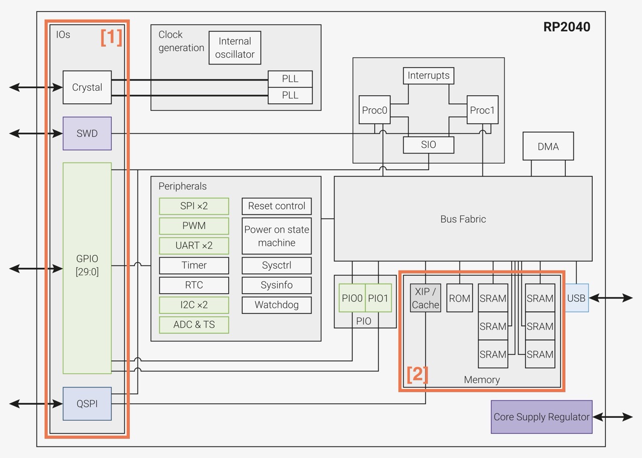
Memory Layout
The board features 264 kilobytes of ultra-fast temporary memory (SRAM) split into six independent banks, allowing its processing units to access data simultaneously without getting stuck in a digital line. It also includes a 2-megabyte flash memory chip soldered directly onto the circuit board. This storage chip acts like a tiny hard drive, securely saving your written program files even when the battery or power cord is completely disconnected. See box [2] in the image above.
Power System
The board is designed to handle multiple energy sources safely and efficiently. You can power it directly through a standard 5-Volt USB-C port, or attach a small rechargeable battery to the dedicated power pads on the bottom. The circuit board features a built-in battery charging system and internal regulators that cleanly drop incoming power down to 3.3 Volts for external parts, and then further down to 1.1 Volts to safely run the delicate internal logic.
Hardware Communication Blocks
The board contains dedicated, hardwired internal circuits designed to speak standard electronic languages, providing 1 UART, 1 SPI, and 1 I2C interface routed directly to the outer pins. It also features a modern, native USB Type-C controller built right into the system. This allows the board to stream data to a laptop, receive new code, or even act as a computer keyboard and mouse without slowing down the main processing logic.
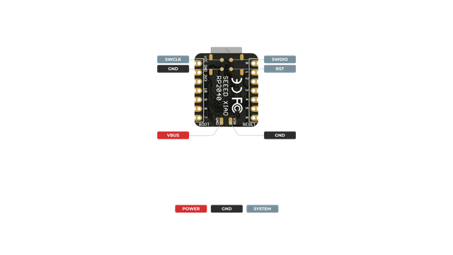
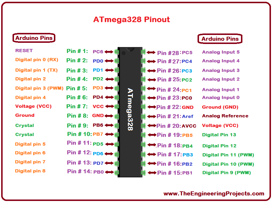
In the image below you can see a quick reference for pinout and pin functions. Full details, including electrical specifications and package drawings, can be found in Chapter 5 of the datasheet.
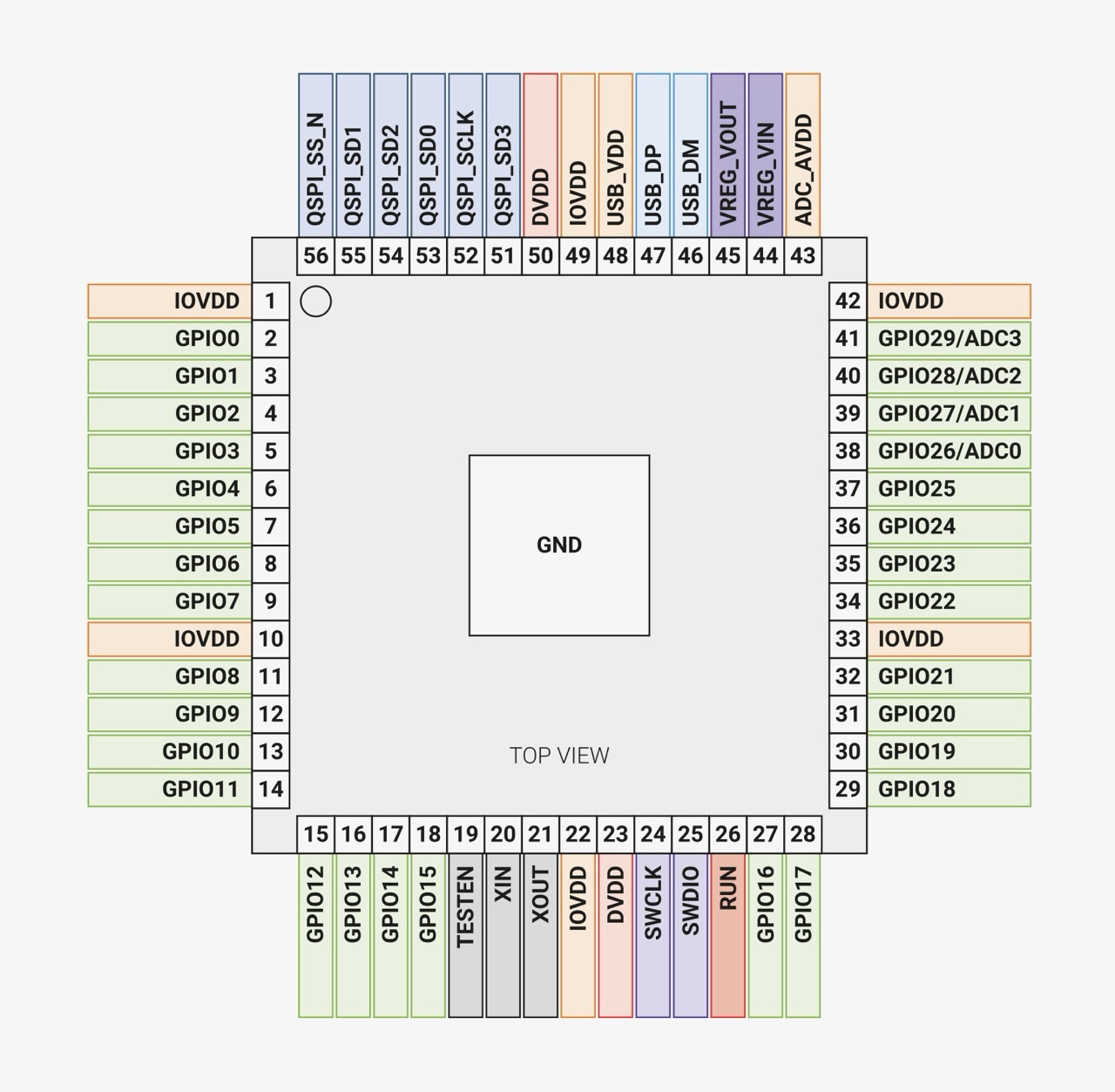
On the other hand, on the XIAO the footprint is way to small to offer the same amount of pads. There’s simply not enough physical edge space to break out all 29 GPIO pins, so there are only 11 exposed pads [see image below].
ATmega328P
The ATmega328P is the microcontroller chip itself, made by Microchip Technology, an 8-bit AVR microcontroller.
The ATmega328P is single-core, 8-bit, AVR, and tops out around 20MHz — but because almost every AVR instruction executes in a single clock cycle, it reaches close to 20 million instructions per second at that clock speed. The CPU core talks straight to a small set of memory-mapped peripherals with nothing else in between.
Memory Layout
The ATmega328P keeps three separate, small, purpose-built memory spaces:
- Flash — 32kB. The program itself, split into an application section and an optional boot loader section.
- SRAM — 2kB. Shared between 32 general-purpose registers, 64 standard I/O registers, 160 extended I/O registers, and the actual working RAM.
- EEPROM — 1kB. A separate byte-addressable space that survives power loss — good for calibration values or saved settings — rated for 100,000 write/erase cycles [vs. 10,000 for the flash].
Power System
The ATmega328P has no on-chip voltage regulator — it runs its core logic directly off VCC [1V8 - 5V5 depending on speed grade]. AVCC ties to VCC through a small filter, and AREF supplies the ADC’s reference voltage.
I/O Pins & Communication
23 general-purpose I/O lines split across three ports — PORTB [8 pins], PORTC [7 pins, mostly ADC-capable], and PORTD [8 pins], each independently configurable per-bit as input or output with optional internal pull-ups. For serial communication specifically there are three dedicated hardware blocks: a full USART, an SPI interface, and a TWI [I2C compatible] 2-wire interface.
The Morse Code
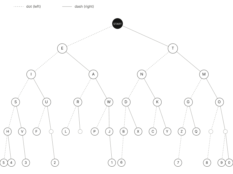
Years ago, before I’d even know how to write code, I came across the binary tree representation of the Morse Code. It looked a bit complicated, but once I knew how to traverse through tree nodes the representation was more than logical. The Code itself is comprised of dots and dashes, and by mixing these you get different results.
H → .... // left > left > left > left
R → .-. // left > right > left
A → .– // left > right
C → -.-. // right > left > right > left
H → .... // left > left > left > left
 *Prompt4.2
The logic behind the tree representation is simple – the parent nodes are prioritezed to have the most frequently occuring letters. Naturally, we start with E and T. To get a letter/characters we traverse down the tree as follows: dots to the left, dashes to the right.
The Components
1x Arduino UNO
1x LCD
1x LED
2x 220Ω resistors
1x 10kΩ resistor
1x 100kΩ potentioemeter
1x 0.03Ω button
?x male-to-male jumper wires
The Code
As I have learned coding in university, this was not difficult for me. Nevertheless, as we had learned the basics of procedural programming in Java, which has the same roots as C/C++, hence the syntax was quite understandable. I was only left to prompt the logic and the pin addresses I had used to connect the Ardunio UNO to the rest of the components.
Please refer to the resources section for the complete code file.
Block 1: Library & Pin Setup
C++

#include <LiquidCrystal.h>
const int rs = 12, en = 11, d4 = 5, d5 = 4, d6 = 3, d7 = 2;
const int ledPin = 8;
const int buttonPin = 9;
Block 2: Display Tracking Variables
C++

int inputCol = 7;
int outputCol = 8;
String outputText = "";
inputCol is for the dots/dashes row, outputCol for the decoded letters row. outputText saves all decoded letters.
Block 3: Timing Variables
C++

unsigned long dotDuration = 0;
unsigned long dashDuration;
unsigned long nextCharDuration;
unsigned long spaceDuration;
unsigned long startTime, pressTime, releaseTime;
Block 4: Morse Code Table
C++

struct MorseMap { const char* code; char letter; };
MorseMap morseTable[] = {
  {".-", 'A'}, {"-...", 'B'}, ...
};
Block 5: Decoder Function
C++

char decodeMorse(String code) {
  for (int i = 0; i < 26; i++) {
    if (code == morseTable[i].code) return morseTable[i].letter;
  }
  return '?';
}
Block 6: Calibration in setup()
C++

lcd.print("Press 3 dots.");
for (int i = 0; i < 3; i++) {
  while (digitalRead(buttonPin) == LOW);   // wait for press
  startTime = millis();
  while (digitalRead(buttonPin) == HIGH);  // wait for release
  pressTime = millis() - startTime;
  totalDuration += pressTime;
}
dotDuration = totalDuration / 3;
dashDuration = dotDuration * 3;
Block 7: Button in loop()
C++

if (digitalRead(buttonPin) == HIGH) {
  startTime = millis();
  while (digitalRead(buttonPin) == HIGH);
  pressTime = millis() - startTime;

  if (pressTime < dashDuration) { lcd.print("."); currentMorse += "."; }
  else                          { lcd.print("-"); currentMorse += "-"; }
  inputCol++;
  releaseTime = millis();
}
currentMorse.
Block 8: Press gap 
C++

unsigned long gapTime = millis() - releaseTime;

if (gapTime > nextCharDuration && gapTime < spaceDuration) {
  // decode the current letter
}
if (gapTime >= spaceDuration) {
  // insert a space (new word)
}
*Prompt4.3
Output
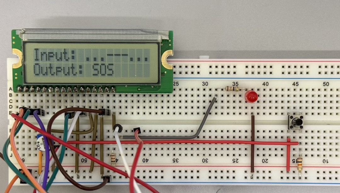
In this video I am trying to output “… — …” which stands for SOS.
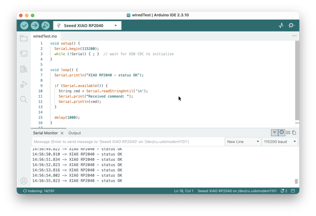
Communication
This code sets up USB serial at 115200 baud, then in a loop: prints a status message every second, and if it receives any incoming text, it reads it and echoes it back — basically a simple two-way “heartbeat + echo” test over serial. To make this test I used an RP2040.
C++

void setup() {
  Serial.begin(115200);
  while (!Serial) { ; }  // wait for USB CDC to initialize
}

void loop() {
  Serial.println("XIAO RP2040 - status OK");

  if (Serial.available()) {
    String cmd = Serial.readStringUntil('\n');
    Serial.print("Received command: ");
    Serial.println(cmd);
  }

  delay(1000);
}
*Prompt4.4
Conclusion
This was my first time ever coming close to embedded programming. Years ago, I tried “learning” electronics on my own, but that ending very quickly, as I was relatively bad at google.
At first, when we began the group assignment, the local lecture was very interesting and digestable, but when it came down to putting the knowledge into action I did not know what to do. But the very last minute, during our regional review, when I got the code working I regained my hope in learning electronics.
Resources
• Morse Code Decoder
• Serial Monitor Test
Prompts
Prompt4.1 Create an illustration of a resistor color scheme. Use a light gray background for the colored section. The text showing the Ohm correspondences should be medium gray, whereas the text next to it using the color code (RGB 157, 157, 157).
Prompt4.2 Create a minimalist, monochrome visual of a binary tree representing the Morse Code alphabet. The design should be neat avoiding any color highlights as it will be on a website with light and dark modes. The tree should be organized by starting with E and T at the top. To find a character, the user will traverse the tree: a dot indicates a move to the left child, while a dash indicates a move to the right.
Prompt4.3 Create an Arduino program that merges a button-controlled LED with a 16x2 LCD display [pins 12, 11, 5, 4, 3, 2] to build a Morse code input decoder. The program should begin with a calibration phase in setup() where the user performs three button presses to define and store an average dot duration using millis(). In the main loop(), the code must measure subsequent button presses to control an LED and classify inputs as either a dot or a dash, where based on the initial calibration three dot durations are equal to a dash.
Prompt4.4 Show wired communication with a microcontroller – a USB serial “heartbeat + echo” test on the XIAO RP2040.