Week 11: Networking and Communications
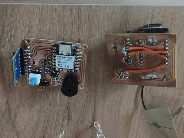
*Two PCBs connected via ESP-NOW
Group Assignment
During networking week, Mariam and I learned to control hardware over a network by connecting two ESP32 C3s via the MQTT protocol and a public HiveMQ broker. We started by establishing basic data transmission between a designated publisher board and a subscriber board, such as sending a simple “hello” message. This initial experiment taught us how to configure the PubSubClient library, manage network subscriptions, and read data payloads through callback functions.
Next, we introduced Mariam’s joystick button to trigger these network messages. Mariam updated her publisher code to send data only when the pin state changed, so when she would press the button I would receive “Pressed!” message. And once this was achieve, the only thing left to do was to put the commands into actions.
Finally, we applied these concepts to remotely deploy my drone rescuing parachute. The receiver board would rotate the connected servo when the joystick message arrived. This final project successfully demonstrated an end-to-end IoT orchestration by bridging a physical sensor input on one network node to a mechanical actuator on another.
Individual Assignment
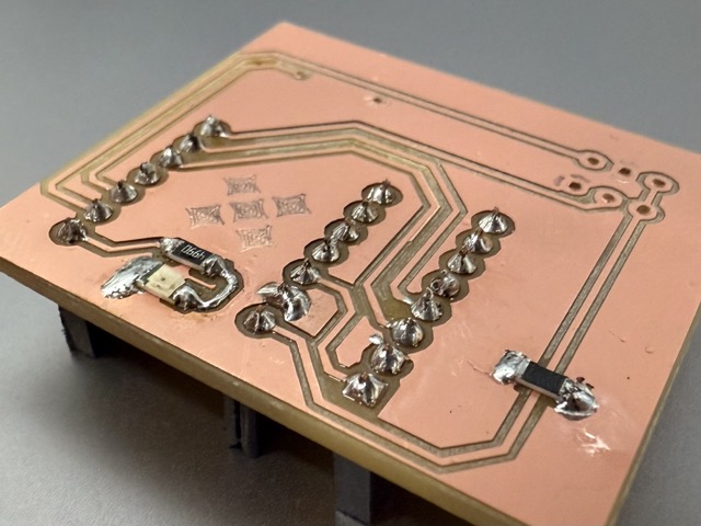
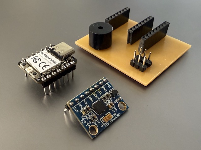
This week’s individual work is based on the results of weeks 8 and 9. In these consecutive two weeks I had designed and produced two iterations of a PCB – the first iteration had male-to-female pin headers for removability week 8, whereas the second iteration had surface-mount components week 9.
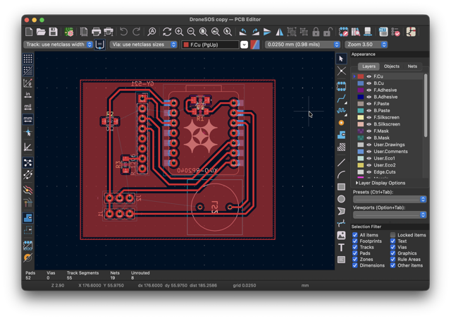
Initially, in week 8, I had a XIAO RP2040 in the place of the MCU, but as the footprints are the same, I easily swapped it with a XIAO ESP32 C3 [image below], as these have a built-in WiFi antenna. This helped me skip the production of a new board, as the RP2040 simply would not allow me to connect to another WiFi compatible MCU.
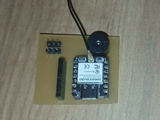
What was the assignment about?
I took a pair of XIAO ESP32 C3s [image below], each wired to its own passive buzzer, and connected them via ESP-NOW. Since this week’s requirement is that both nodes be addressable rather than just taking turns blindly, I gave each board an identity: at boot, a board reads a strap pin and decides whether it’s Node A or Node B, which also sets which pin its buzzer is on [D2 for Node A, D3 for Node B]. Node A starts by sending a packet with a random tone addressed to Node B’s ID; Node B’s radio picks up the packet, checks that the address matches its own, plays the tone, and sends a reply addressed back to Node A with a new random tone — so the two boards keep answering each other, each one only ever reacting to packets meant for it.
Node A: week 8
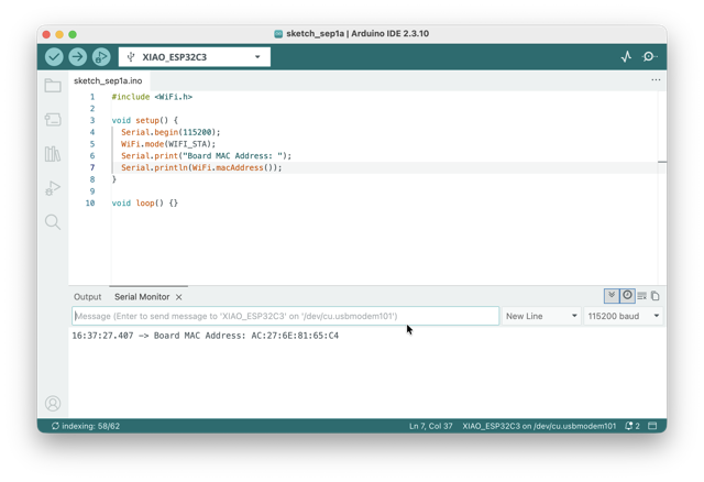
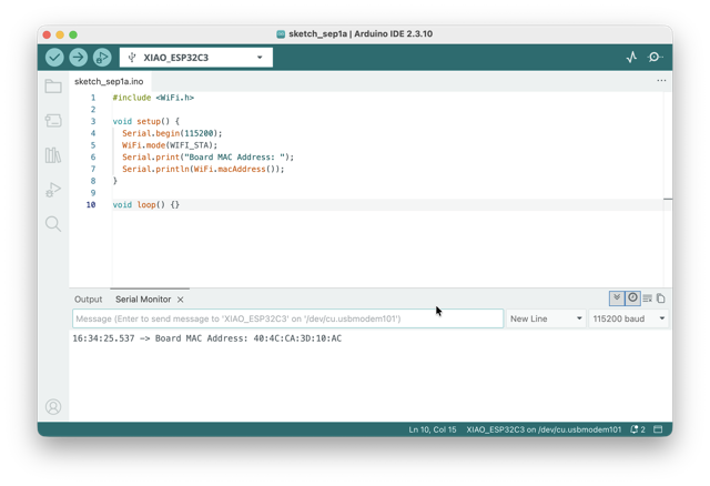
To find the MAC address for this ESP I uploaded the following simple code:
C++

#include <WiFi.h>

void setup() {
  Serial.begin(115200);
  WiFi.mode(WIFI_STA);
  Serial.print("Board MAC Address: ");
  Serial.println(WiFi.macAddress());
}

void loop() {}
The ESP32 manages all 2.4 GHz radio functions, including ESP-NOW, through its central Wi-Fi hardware controller. Including <WiFi.h> lets you initialize that radio hardware into station mode (WIFI_STA) and access the underlying factory MAC address built into the chip.
Once the code was run in the Serial Monitor the following was output: AC:27:6E:81:65:C4 This will be used later in the firmware.
Node B: week 9
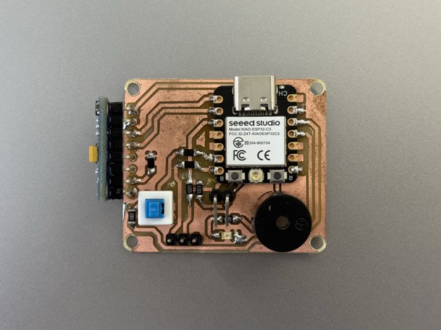
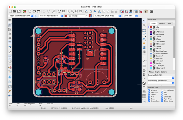
To find node B’s MAC address the same code was used to obtain its unique identifier.
Protocol Note
I used ESP-NOW, Espressif’s connectionless protocol built on top of the 802.11 radio. Unlike regular WiFi it doesn’t join a network or talk to a router — boards just send short packets directly to each other’s MAC address [or to a broadcast address, which is what I used here], which keeps the setup light for two microcontrollers passing small pieces of data back and forth. I picked it over something like MQTT because there’s no broker involved — it’s a direct board-to-board link, which fit the “addressable nodes” requirement well since I could put the addressing logic straight into the packet itself instead of relying on network infrastructure to route it.
- ESP-NOW reference: Espressif ESP-NOW docs
- Arduino core examples: ESPNow examples, arduino-esp32
The Code
Here’s the prompt I had used to generate the code:
I have two XIAO ESP32 C3 boards — one with a GY-521 [MPU6050], the other with a passive buzzer. Connect them over ESP-NOW so the sensor board’s tilt controls the buzzer’s pitch. Simplify the mapping to a single tilt axis rather than juggling all three — use whichever gives the cleanest, most intuitive control, with tilt in one direction raising the pitch and the other lowering it. Add smoothing/filtering so sensor noise doesn’t make the buzzer warble. See the wiring below:
MPU6050:
SDA → D1
SCL → D0
VCC → 3.3V
GND → GND
Buzzer:
(+) → D2 // on the first board
(+) → D3 // on the second board
Both boards run the same file: there’s no separate sender/receiver sketch. Which node a board becomes [and which buzzer pin it uses] is decided at boot by reading a strap pin.
*Prompt11.1
C++

#include <esp_now.h>
#include <WiFi.h>

// ---------------- ADDRESSING ----------------
#define ADDR_PIN 9      // strap pin read once at boot to decide identity
uint8_t MY_ID;          // this board's address (0x01 or 0x02)
uint8_t PEER_ID;        // the address we talk to

// ---------------- BUZZER ----------------
// Node A's buzzer is wired to D2, Node B's is wired to D3 — the pin is
// picked at runtime based on which node this board turns out to be.
uint8_t BUZZER_PIN;

// ---------------- PACKET FORMAT ----------------
typedef struct __attribute__((packed)) {
  uint8_t  sender_id;
  uint8_t  receiver_id;
  uint16_t frequency_hz;
  uint16_t duration_ms;
} message_t;

uint8_t peerMac[] = {0xFF, 0xFF, 0xFF, 0xFF, 0xFF, 0xFF};

void playTone(uint16_t freq, uint16_t dur) {
  ledcAttach(BUZZER_PIN, freq, 8);
  ledcWriteTone(BUZZER_PIN, freq);
  delay(dur);
  ledcWriteTone(BUZZER_PIN, 0);
  ledcDetach(BUZZER_PIN);
}

void sendMessage(uint8_t receiver, uint16_t freq, uint16_t dur) {
  message_t msg;
  msg.sender_id    = MY_ID;
  msg.receiver_id  = receiver;
  msg.frequency_hz = freq;
  msg.duration_ms  = dur;
  esp_now_send(peerMac, (uint8_t*)&msg, sizeof(msg));
}

void OnDataRecv(const esp_now_recv_info_t *info, const uint8_t *data, int len) {
  if (len != sizeof(message_t)) return;
  message_t msg;
  memcpy(&msg, data, sizeof(msg));

  if (msg.receiver_id != MY_ID) return;   // not addressed to me — ignore

  playTone(msg.frequency_hz, msg.duration_ms);
  delay(200);
  sendMessage(msg.sender_id, random(300, 2000), 250 + random(0, 250));
}

void OnDataSent(const uint8_t *mac, esp_now_send_status_t status) {}

void setup() {
  Serial.begin(115200);
  pinMode(ADDR_PIN, INPUT_PULLUP);

  MY_ID      = (digitalRead(ADDR_PIN) == LOW) ? 0x01 : 0x02;
  PEER_ID    = (MY_ID == 0x01) ? 0x02 : 0x01;
  BUZZER_PIN = (MY_ID == 0x01) ? D2 : D3;

  WiFi.mode(WIFI_STA);
  esp_now_init();
  esp_now_register_recv_cb(OnDataRecv);
  esp_now_register_send_cb(OnDataSent);

  esp_now_peer_info_t peerInfo = {};
  memcpy(peerInfo.peer_addr, peerMac, 6);
  peerInfo.channel = 0;
  peerInfo.encrypt = false;
  esp_now_add_peer(&peerInfo);

  randomSeed(analogRead(0));

  if (MY_ID == 0x01) {
    delay(2000);
    sendMessage(PEER_ID, random(300, 2000), 300);
  }
}

void loop() {}
How the communication happened
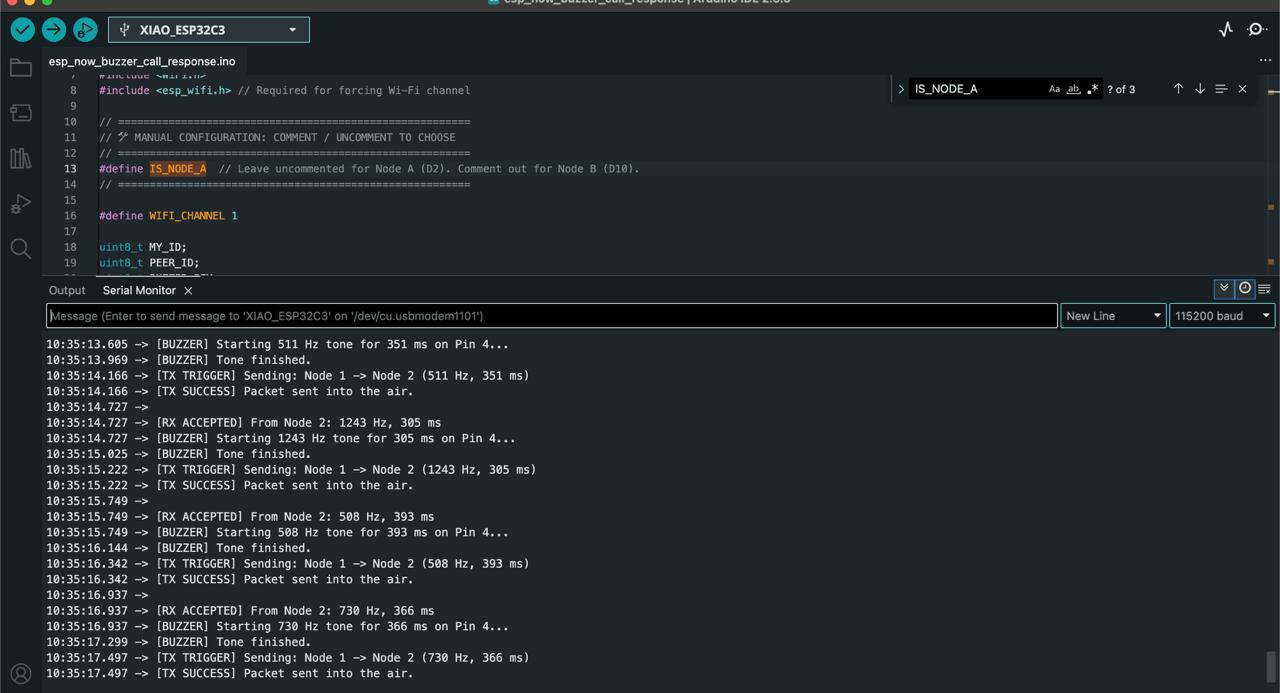
Both boards register the same broadcast MAC address [FF:FF:FF:FF:FF:FF] as an ESP-NOW peer, so a packet sent by either board is physically received by both radios. Node A sends the first packet after boot; whichever board’s callback sees a packet addressed to itself plays that tone and immediately replies with a new packet addressed back to the sender. That reply is what turns it into a genuine back-and-forth instead of a one-shot ping.
How the address sets each board
At boot, each board reads ADDR_PIN (D9). If it’s pulled to ground, the board decides MY_ID = 0x01 (Node A); if it’s left floating, the internal pull-up reads it as HIGH and the board becomes MY_ID = 0x02 (Node B). The same read also picks BUZZER_PIN (D2 for Node A, D3 for Node B), so one identical file gets flashed onto both boards — nothing is hardcoded per board.
Which function sends, which one receives
sendMessage()is the only function that callsesp_now_send(). It stamps every outgoing packet withMY_IDas the sender and whichever board it’s meant for as the receiver.OnDataRecv()is the ESP-NOW receive callback, registered withesp_now_register_recv_cb(). This is where addressing is enforced:if (msg.receiver_id != MY_ID) return;drops any packet not meant for this board. If it is addressed to it, it plays the tone and callssendMessage()to reply.OnDataSent()just confirms whether the last send succeeded at the radio layer — it isn’t part of the addressing logic.
Result
In the video below you can hear how the output from the buzzers shuffel between each other.
Conclusion
I must say, I did not think networking week would turn out so exciting. Surely, it is not magic. But working with MQTT went quite smoothly, whereas the practices of a subscriber and publisher were quite intuitive. I also liked working with ESP NOW, it is quite simple!
References
The code works for both node A and B!
Prompts
Prompt11.1 I have two PCBs, each have an ESP32-C3 and passive buzzers. I want them to communicate via ESP-NOW back and forth. First one pings at a random frequency, then the other waits for the first to end and they continue back and forth — do you have better suggestions, given that both nodes need to be addressable for a networking assignment?
First ESP has its buzzer on D2, the second on D3 — update the code so the pin is picked automatically per board instead of hardcoded, without needing two different files.