Project Development
Sketches
I had this sketch from week 2 of FabAcademy, but the smaller images below is when I started actually thinking about the final shape of the device’s case.
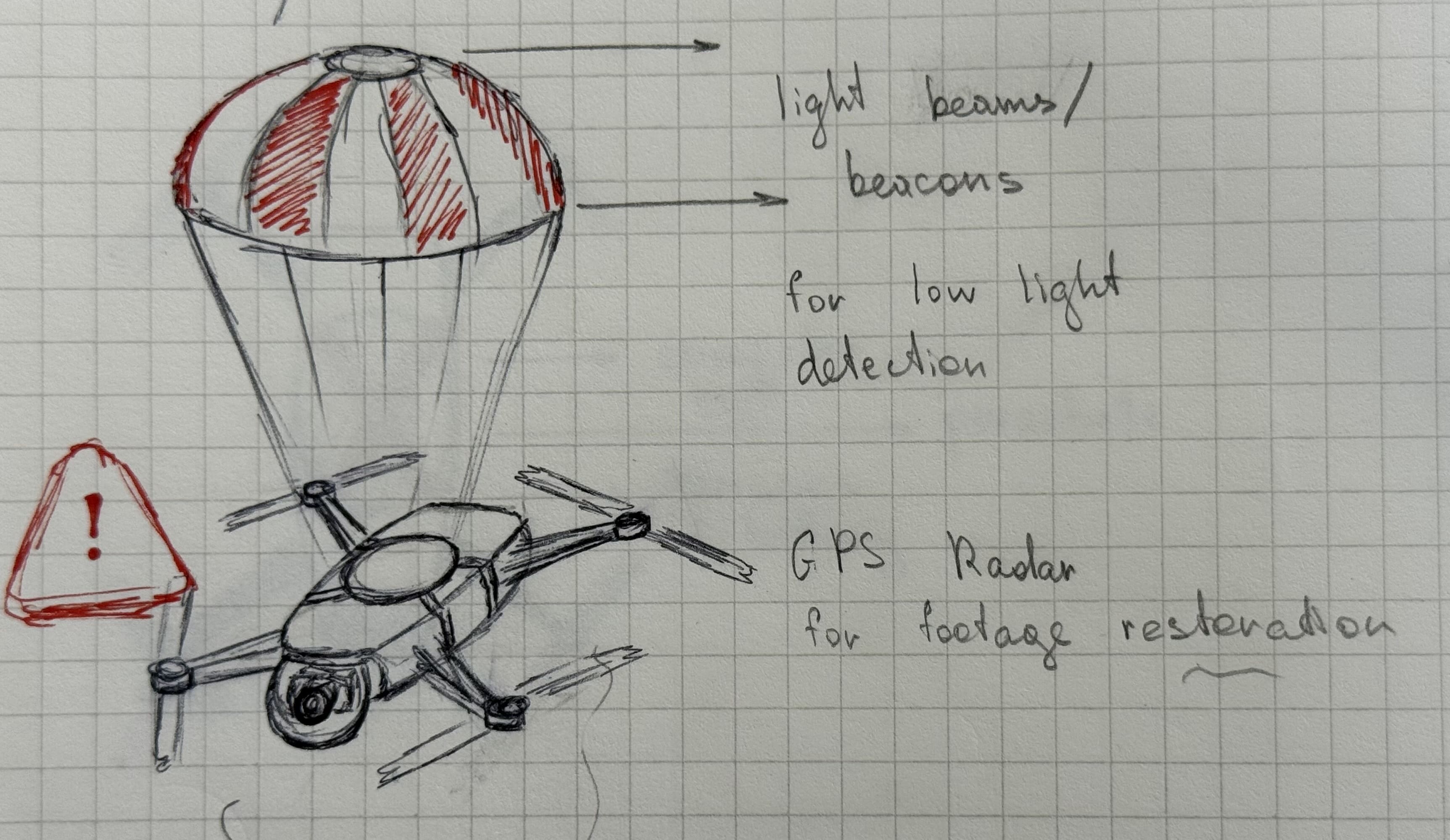
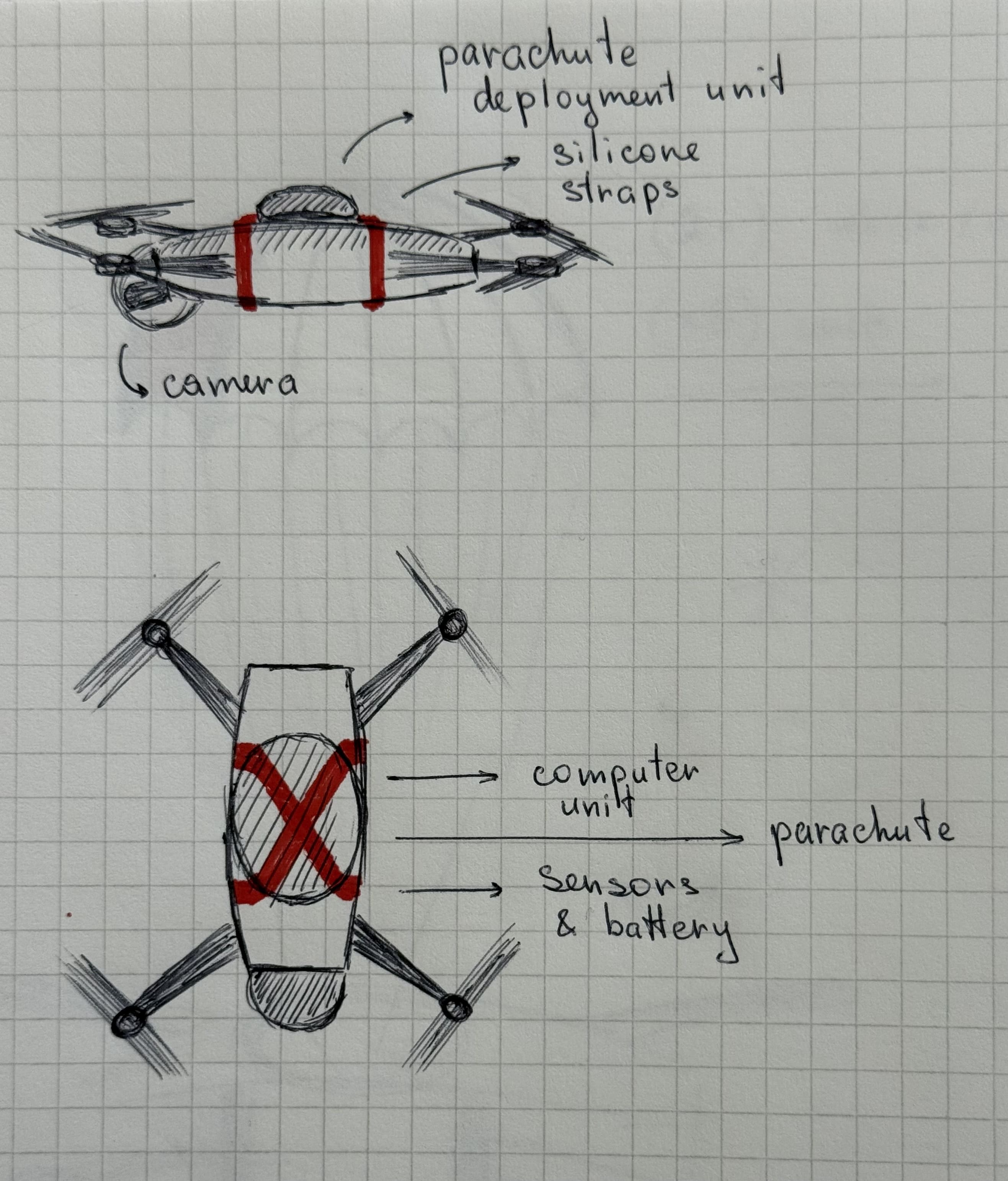
Blender
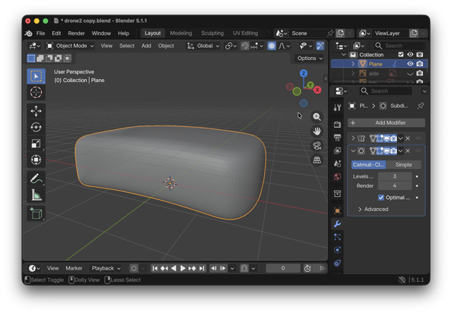
It all began with me designing the casing in Blender. I skeched out the silhouette that I then outlined, and started creating. As I am not very comfortable with mesh-based applications, I decided to find a tutorial on YouTube that would make a body similar to what I had in mind.
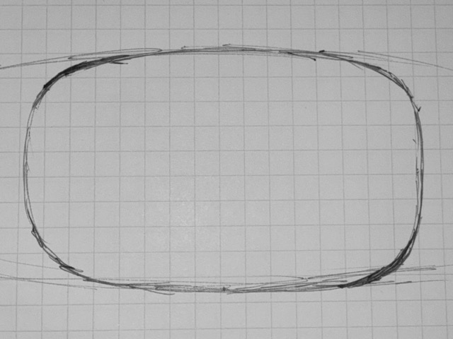
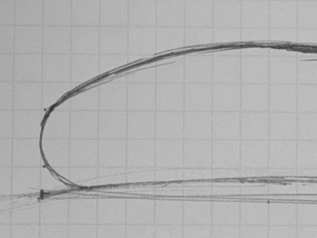
In this case I had two options: a soap bar, and an Apple Magic Mouse. The tutorials on the soap bar shape of my choice were not abundant online, so my second option worked better.
Blender to Fusion
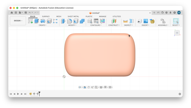
I faced some issues when switching from a mesh object to a solid body. As I wanted to make the case parametric, I though I could simply import the mesh into Fusion, and solidify. On the other hand, working with high poly object in Blender did not seem logical, especially when I had the idea to switch apps mid-design.
Similarly, while I feel more comfortable with parametric apps I am not advanced either. So, it was more difficult to achieve a more “organicly” shaped object. Naturally, I was left to make something very basic. There’s a difference between simple and basic.
Sample Printing
Because converting the complex mesh model into a solid body proved too difficult and time-consuming, I shifted my focus to the mechanical components. The cross-section images below show how I used a side cutout of the case to determine internal dimensions. This view also helped me map out the movement of the doors based on the spring mechanics.
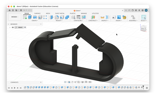
To keep the springs inside their housing, I drilled a hole using a hand drill and secured them with a bolt and nut, as shown in the right image below.
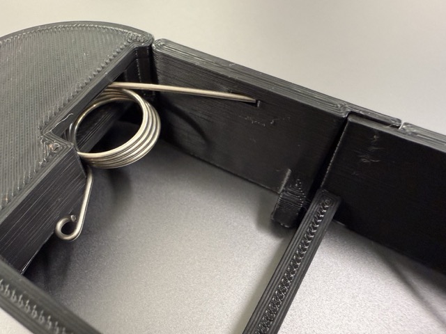
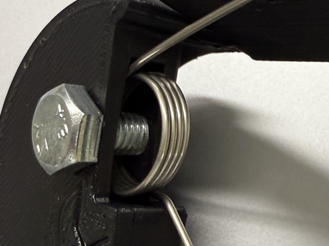
While this setup was not the prettiest, it was good enough to quickly test and iterate on the design.
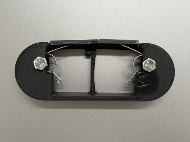
I first printed all the samples in PLA. This was more economical and less risky, as PETG can sometimes be trickier to print. This initial print also helped me evaluate the stiffness of the lever. Because it turned out a bit too stiff, I shaved down one of its sides to determine the ideal thickness [right side of the lever in the video below].
Servo Motor
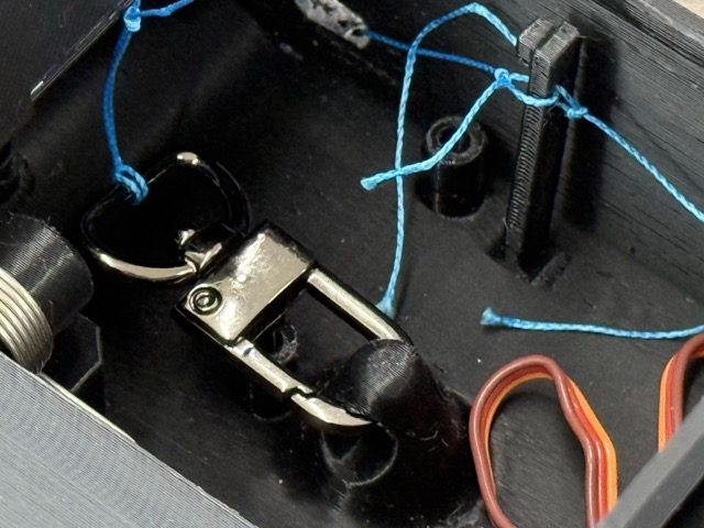
For the servo, I was suggested to use a metalic geared servo, instead of a plastic one. As the doors are unlatched using an in-place printed hooked-lever attached to a servo, I wanted to test the stiffness of it. And the lever is attached to the servo using some strong theard for in-water use.
Finally, to test the stiffness, I used the build-in Arduino <Servo.h> library, suggested by Maxime, one of my local instructors. Just in case I checked an online blog [Instructables.com] before generating the code.
C++

#include <Servo.h>

Servo doorServo;  // Create a servo object to control the door

// Your custom adjusted angles (20 for closed, 120 for open)
const int CLOSED_POSITION = 20;   // Default position (Closed)
const int OPEN_POSITION = 150;    // Open position

void setup() {
  Serial.begin(9600);            // Initialize serial communication at 9600 bps
  doorServo.attach(3);           // Connect the servo signal to digital pin 3

  doorServo.write(CLOSED_POSITION); // Set door to default closed position at startup

  // Print instructions to the Serial Monitor
  Serial.println("Door Control Ready!");
  Serial.println("Type 'O' to Open, 'C' to Close.");
}

void loop() {
  // Check if bytes are available to read from the serial port
  if (Serial.available() > 0) {
    char input = Serial.read();  // Read the incoming character

    // Check the command
    if (input == 'O' || input == 'o') {
      doorServo.write(OPEN_POSITION);
      Serial.println("Status: Opening door...");
    }
    else if (input == 'C' || input == 'c') {
      doorServo.write(CLOSED_POSITION);
      Serial.println("Status: Closing door...");
    }
  }
}
*Prompt.F1
Battery Integration
The battery connects to the XIAO’s onboard battery input, and charges via its USB-C port. One limitation: the board runs on either USB or battery, not both at once. So during testing, I had to unplug one to use the other [e.g., unplugging the battery when I needed USB for serial monitoring].
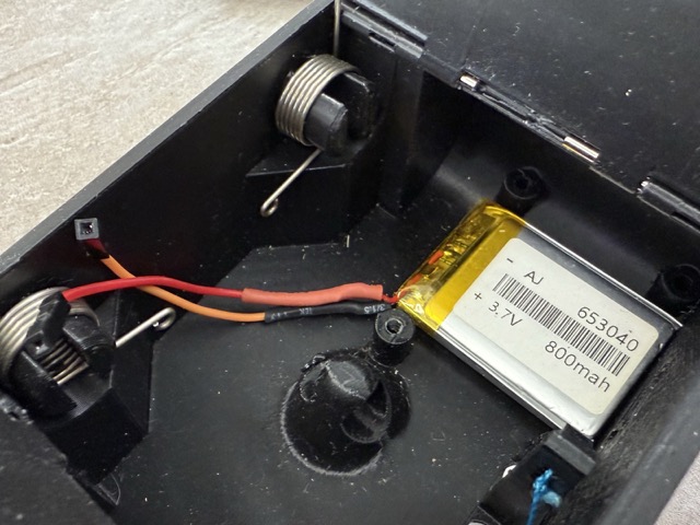
For the battery, I will use a 2.54mm-2P pitch [pin/hole] JST XH 2 pin micro connector which are sturdy, and will not loose easily. This comes factory built with the battery. I might have to extend the wires.
Nevertheless, in my case design I lefted the PCB both to be attached with screws, and left some spacing for the battery to be tucked underneath [I also plan on using a double sided tape to secure it in place].
Mechanical Parts
I started working on the CAD model more rigorously during the fifteenth week. In the images below you can see the initial design of the models which soon developed into more advanced versions.
For example, in the left image, the door hinges cannot be removed once the rods are pushed into the case. So later, for easier replacement, I added some slits to be able to push these out with the use of some metalic blunt tools.
In the right image there is the knob which “holds” the spring in place. In reality I knew that this would not have functioned well, but I simply wanted to test how the sping would behave when supressed. Once I had taken these measurements, I designed a invers cone-like shape, which would not let the springs slide out.
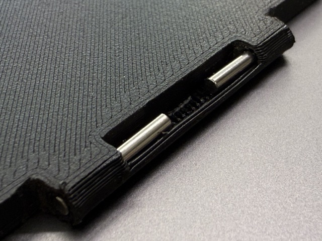
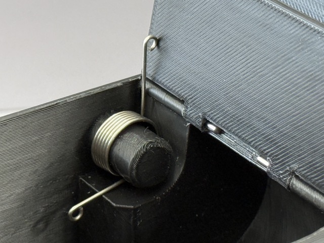
The updated versions are in the images below.
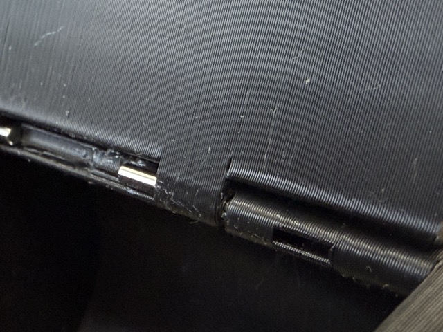
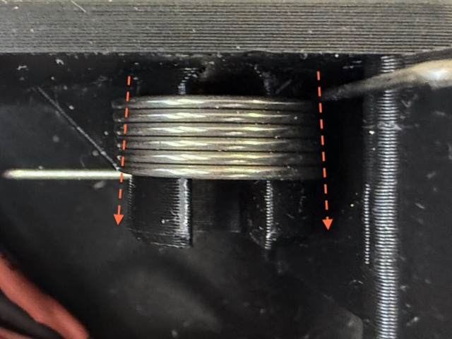
And finally the case with closed doors [image below].
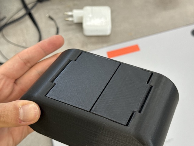
Electronics
• 1x XIAO ESP32 C3 • 1x MPU6050 Accelerometer and Gyroscope • 1x 5V Servo Motor • 1x 3.7V 800mAh LiPo Battery • 1x Switch Button • 1x Passive Buzzer • 1x 1206 SMD LED • Other smaller components
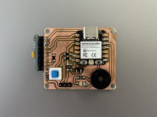
*The final PCB
The battery did not have a specific place within the case. So to secure it, and allocate a tight corner I lifted the PCB, which would need to be secured in place by screws, so this lift hadcreated space for the battery. It was basically hidden under the PCB, and held in place using a double sided tape.
Servo to Lever
The lever has two holes inside to make a relyable dead knot. In the video below you can see how I am tying a “bowline” knot, which does not untangle. And as the thread was thin and the holes small I took a pair of tweezers and started knotting.
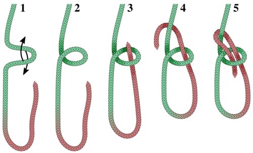 Here’s a simple infographics on how to tie the know [image below]. It is important not to mess up the order of loops, meaning which one goes under or above.
In the video below I had recorded the first attempt of me opening the doors by connectingthe positive and negative jumper wires onto the Arduino UNO. No sure why I reached out that time to use an Arduino, but the firmware was extremely simple, it was just pulling and releasing the lever every 2 seconds.
Parachute
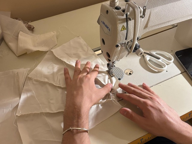
As I am aiming for precision, for the parachute I cut out the individual fabric shapes on the lazer cutter. As the facbric was quite thin, but everything worked out fine. I had some doubts that it would have not worked out, but in fact it was better. As the fabric is made of nylon, the edges simply melted and fused together and I had no more raw edges. So basically, due to this I had no fraying!
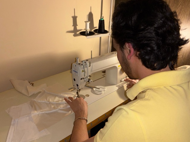
Once all the 13 of the pieces were ready I went to sew them together. It was quite fast and easy as I have some experience in sewing. Although the thread run offs bothered me, I did not clean much of them up.
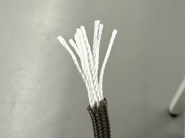
I chose paracord to securely connect the canopy to the device. Paracord types vary by diameter and inner thread count. Because it is reliably used in skydiving and paragliding, I knew its strong inner strands would be perfect, so I grabbed a spool.
I am using the third type [left image below], 4mm thick, with 8 thinner threads inside [the inner quantity can vary].
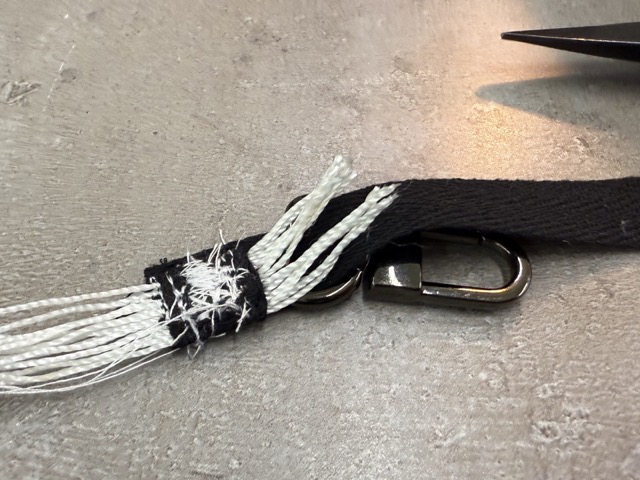
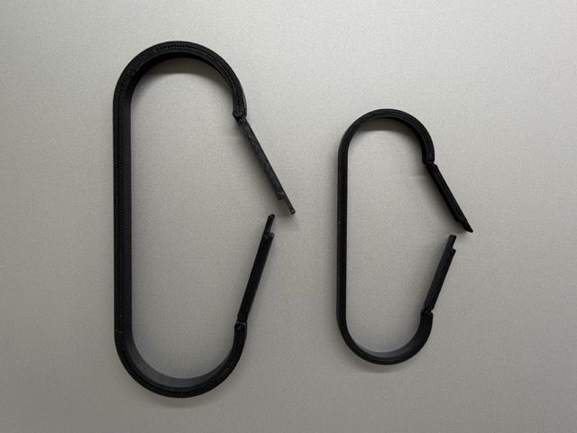
I avoided permanently attaching the parachute to the device to prevent tearing and tangled strands. Instead, I made it detachable using a carabiner [image below]. To connect the parachute, I gathered all the strands and sewed them rigorously across the grain [right image above]. For maximum security, I wrapped the strands in a thick cotton ribbon and stitched it directly to the carabiner’s key loop.
The Code
The whole device operates based on the ~200 line of code below.
How does it work?
-
Raw Data Conversion: The MPU6050 configured to its default ±2g range yields raw 16-bit signed integers. These must be divided by a sensitivity scale factor of 16384 LSB/g to convert the data into standard gravitational units [g].
-
3D Vector Magnitude: The system calculates the net acceleration vector Amag using the Pythagorean theorem in 3D space: √(Ax2 + Ay2 + Az2) This eliminates device orientation dependence, as resting on the pad equals 1.0g and true weightlessness equals 0.0g.
-
Noise & Threshold Filtering: Due to motor vibrations and aerodynamic drag, true 0.0g is rare. The code uses a 0.30g threshold to accommodate this noise, considering any total vector below this value as a state of free-fall.
-
Time Debouncing: To prevent premature deployments from temporary zero-g anomalies [like engine burnout or aerodynamic buffeting], a non-blocking millisecond timer ensures the acceleration vector continuously remains below 0.30g for a full 30ms before executing the deployment function.
C++

/*
  XIAO ESP32-C3 Recovery System

  Connections:
  MPU6050
    SDA -> D1
    SCL -> D0
    VCC -> 3.3V
    GND -> GND

  Buzzer
    + -> D10
    - -> GND

  Servo
    Signal -> GPIO21

  Battery Monitor
    Divider Output -> D3
    Divider Ratio = 1:1
*/

#include <Wire.h>
#include <MPU6050.h>
#include <ESP32Servo.h>

MPU6050 mpu;
Servo parachuteServo;

// Pins
const int BUZZER_PIN = D10;
const int SERVO_PIN = 21;
const int BATTERY_PIN = D2;

// Servo positions
const int CLOSED_POS = 90;
const int OPEN_POS = 180;

// Free-fall settings
const float FREE_FALL_THRESHOLD = 0.30;   // g
const unsigned long FREE_FALL_TIME = 30; // ms

bool freeFallStarted = false;
bool parachuteDeployed = false;

unsigned long freeFallStartTime = 0;
unsigned long lastBatteryRead = 0;

// -------------------------
// Battery Functions
// -------------------------
float getBatteryVoltage()
{
  int adc = analogRead(BATTERY_PIN);

  // ESP32-C3 ADC
  float adcVoltage = (adc / 4096.0) * 3.3;

  // 1:1 divider
  float batteryVoltage = adcVoltage * 2.0;

  return batteryVoltage;
}

int getBatteryPercent(float voltage)
{
  if (voltage >= 4.20)
    return 100;

  if (voltage <= 3.20)
    return 0;

  return (int)((voltage - 3.20) * 100.0 / (4.20 - 3.20));
  //return voltage;
}

// -------------------------
// Deploy Parachute
// -------------------------
void deployParachute()
{
  if (!parachuteDeployed)
  {
    parachuteServo.write(OPEN_POS);
    parachuteDeployed = true;

    Serial.println("================================");
    Serial.println("FREE FALL DETECTED!");
    Serial.println("PARACHUTE DEPLOYED!");
    Serial.println("================================");
  }
}

void setup()
{
  Serial.begin(115200);
  delay(1000);

  Serial.println("Starting Recovery System...");

  // I2C
  Wire.begin(D1, D0);

  // MPU6050
  mpu.initialize();

  if (!mpu.testConnection())
  {
    Serial.println("MPU6050 connection FAILED!");
    while (1)
    {
      delay(100);
    }
  }

  Serial.println("MPU6050 connected.");

  // Battery ADC
  analogReadResolution(12);

  // Buzzer
  pinMode(BUZZER_PIN, OUTPUT);
  noTone(BUZZER_PIN);

  // Servo
  parachuteServo.attach(SERVO_PIN);
  parachuteServo.write(CLOSED_POS);

  Serial.println("System Ready.");
}

void loop()
{
  // -------------------------
  // Read MPU6050
  // -------------------------
  int16_t ax, ay, az;

  mpu.getAcceleration(&ax, &ay, &az);

  float ax_g = ax / 16384.0;
  float ay_g = ay / 16384.0;
  float az_g = az / 16384.0;

  float accelMagnitude =
      sqrt(ax_g * ax_g +
           ay_g * ay_g +
           az_g * az_g);

  // -------------------------
  // Free Fall Detection
  // -------------------------
  if (!parachuteDeployed)
  {
    if (accelMagnitude < FREE_FALL_THRESHOLD)
    {
      if (!freeFallStarted)
      {
        freeFallStarted = true;
        freeFallStartTime = millis();

        Serial.println("Possible free fall...");
      }

      if (millis() - freeFallStartTime >= FREE_FALL_TIME)
      {
        deployParachute();
      }
    }
    else
    {
      freeFallStarted = false;
    }
  }

  // -------------------------
  // Alarm after deployment
  // -------------------------
  if (parachuteDeployed)
  {
    static unsigned long lastToneChange = 0;
    static bool highTone = false;

    if (millis() - lastToneChange > 200)
    {
      lastToneChange = millis();

      highTone = !highTone;

      if (highTone)
      {
        tone(BUZZER_PIN, 3000);
      }
      else
      {
        tone(BUZZER_PIN, 1500);
      }
    }
  }

  // -------------------------
  // Battery Status
  // -------------------------
  if (millis() - lastBatteryRead > 1000)
  {
    lastBatteryRead = millis();

    float batteryVoltage = getBatteryVoltage();
    int batteryPercent = getBatteryPercent(batteryVoltage);

    Serial.print("Battery: ");
    Serial.print(batteryVoltage, 2);
    Serial.print(" V | ");

    Serial.print(batteryPercent);
    Serial.print("% | ");

    Serial.print("Accel Magnitude: ");
    Serial.println(accelMagnitude, 3);
  }

  delay(10);
}
Project BOM [Bill of Materials]
| Item | Specification/Description | Price [PPU] | Quantity | Source |
|---|---|---|---|---|
| LiPo Battery | 3.7V, 1200 mAh | $6,80 | 1 | Local Store |
| Case | PLA filament | $13,5 | 0,154 | Inventory |
| Copper Blank | FR-1 4x5 inch | $2,2 | 1 | Inventory |
| Servo Motor | 5V, metallic geared | $19,95 | 1 | Inventory |
| ESP32 | XIAO ESP32 C3 | $4,90 | 1 | Seeed Studio |
| Gyro & Accelerometer | GY-521 | $2,98 | 1 | Inventory |
| Buzzer | 5V, Passive, TMB12A05 | $0,14 | 1 | Inventory |
| Button | 6 pin, push button | $0,13 | 1 | Inventory |
| Resistor | mixed | $0.004 | 6 | Inventory |
| LED | 1206 SMD | $0.007 | 1 | Inventory |
| Screw | – | – | 6 | Inventory |
| Spring | Torsion | $0,24 | 2 | Inventory |
| Shaft Rod | 14x2 mm | $0,02 | 4 | Inventory |
| Pin header | Male | $0,05 | 12 | Inventory |
| Fabric | Water repelling Nylon | $16,5 | 0.2 | Local Store |
| Paracord | Type III, 4mm | $1,5 | 1 | Local Store |
| Carabiner | Looped | $0,75 | 1 | Local Store |


References
• Firmware
STL
• Body
• Bottom Door
• Top Door
• Lever
3MF
• Body
• Bottom Door
• Top Door
• Lever
Parachute
• Parachute – DXF
• Parachute – 3MF
Native Files
Whole Body – Fusion 360 PCB – KiCad ZIP
Prompts
Prompt.F1 Write a basic Arduino Uno sketch that controls a hobby servo motor powered by an external power supply. The servo signal wire is connected to pin 3. The servo must operate via commands sent through IDE’s serial monitor [configured at 9600 baud with Newline line endings]. By default the servo is set to a closed position, but when I type in O the position should switch to Open, and C for Closed.
Prompt.F2 Create an Arduino sketch for XIAO ESP32 C3 drone recovery system using the Wire, MPU6050, and ESP32Servo libraries. The hardware configuration requires MPU6050 I2C pins set to D1 [SDA] and D0 [SCL], a servo signal on GPIO 21, a buzzer on D10, and a 1:1 analog battery monitor divider on D2 using a 12-bit resolution. In the main loop, calculate total acceleration magnitude from scaled MPU6050 g-force values (sqrt(ax^2 + ay^2 + az^2)); if this magnitude drops below a 0.30g threshold continuously for 30 milliseconds, deploy the parachute by rotating the servo from 90 to 180 degrees and print a confirmation message. Once deployed, the system must trigger an alternating dual-tone siren on the buzzer [3000 Hz and 1500 Hz switching every 200 ms]. Finally, every 1000 milliseconds, read the battery voltage, map it linearly to a percentage between 4.20V [100%] and 3.20V [0%], and print the voltage, percentage, and current acceleration magnitude to the Serial monitor at 115200 baud, maintaining a 10 ms delay at the bottom of the loop.