Week 8: Electronics Production
*First and final board of the week.
Group Assignment
Safety training
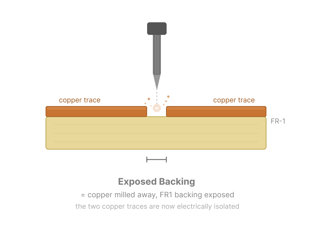
There are two main types of PCB copper blanks: FR-1 and FR-4. We use FR-1, whereas FR-4 is considered toxic.
FR-1: paper-based, less heat-resistant, safer to mill.
FR-4: fiberglass-based, highly heat-resistant, generates hazardous glass dust when cut.
Machine calibration
At our node, we have Roland SRM-20 milling machine. Randomly enough, I found this video from FabLab Aalto. Students from my node, who had graduated in 2023, had used the video to set up the same machine.
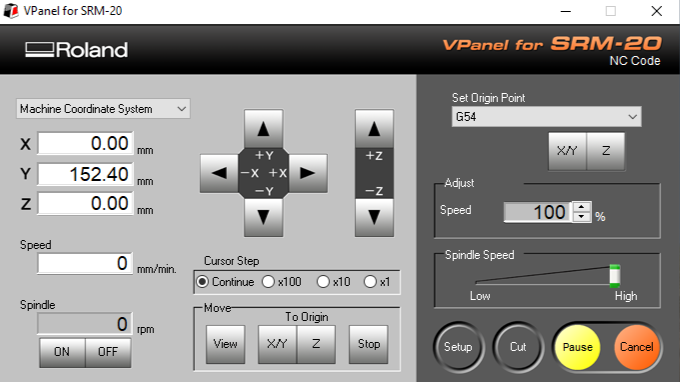
To set your X and Y lines, use the controls to move the cutting bit to your starting spot. This is usually the bottom-left corner. Press the X/Y button, and the machine will mark this exact spot as your zero point.
Whenever you change the bit, the height changes too, so you will need to reset the Z axis. Lower the bit until it is close to the board. Next, use the right hex key to loosen the bit, let it drop gently until it touches the surface, and tighten it back up. Then, just press the Z button to lock in your zero height.
Keep in mind that if you use .nc files, the machine can save a few different starting locations using codes G54 through G59. If your files come from modsproject, it will use G54 automatically.
Test 1: milling
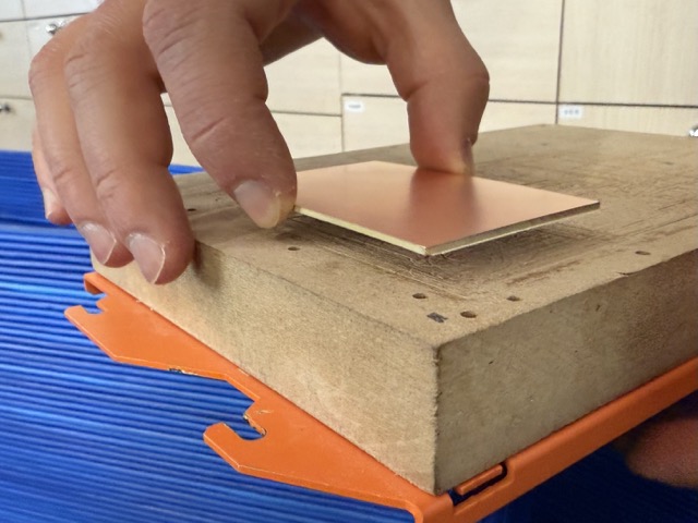
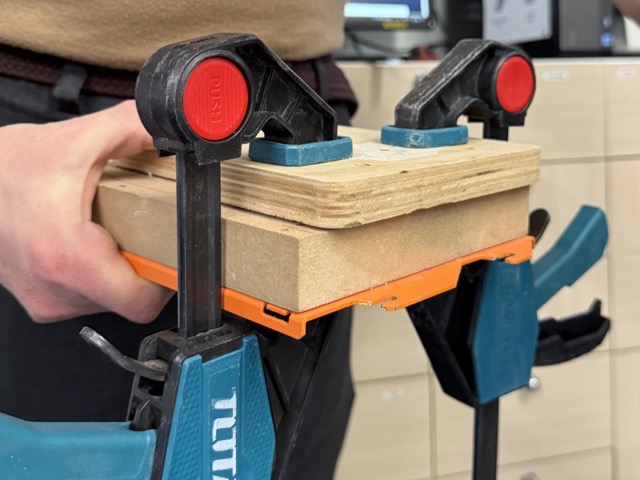
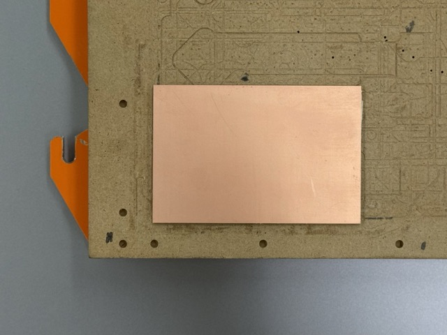
We first attached the copper plate with a double sided tape, and clampped down by covering the plate with a plywood piece [left it clampped for ~5 mins].
 *Prompt8.1
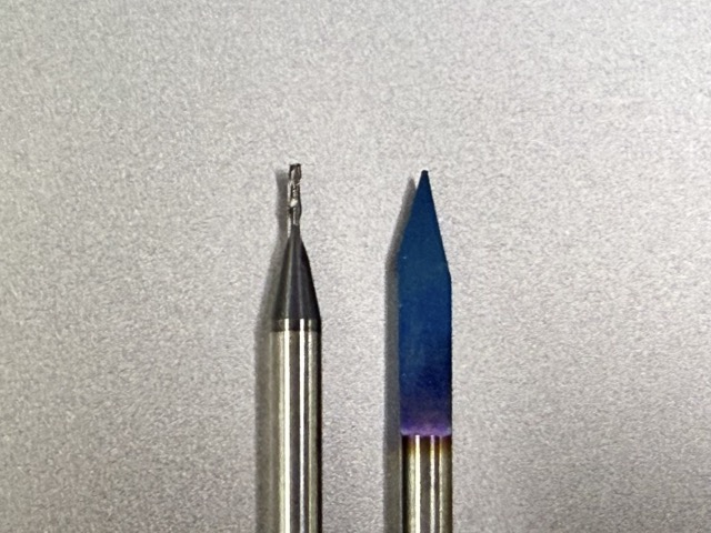
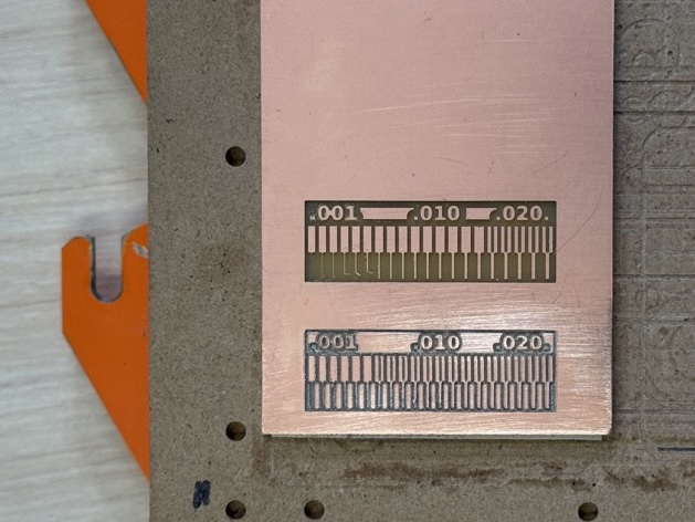
There are two main types of milling bits – V-bit and regular endmill. To test and see the differences between the results of these two we downloaded the ‘traces’ file, and cut it on our laser cutter.
Test 2: etching
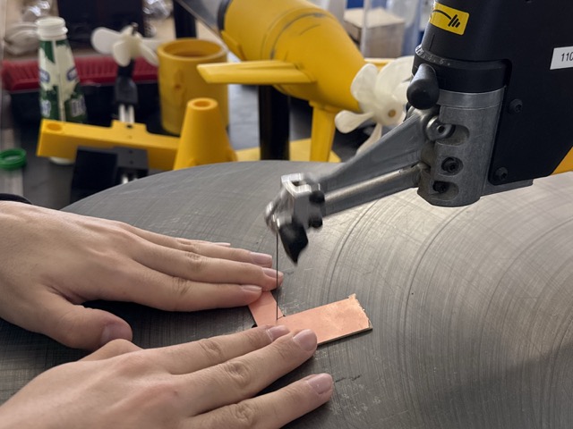
For our group assignent, Mariam and I took a scrap piece of FR-1 PCB blank, and cut it into two parts, using the DeWALT Scroll Saw. Then we painted it on both sides with matte black spray paint, and left it to dry overnight. Again using the ‘traces’ file, we etched it on the laser cutter. The laser was set to a speed of 200 mm/min and a power of 30%–35%.
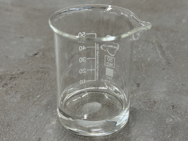
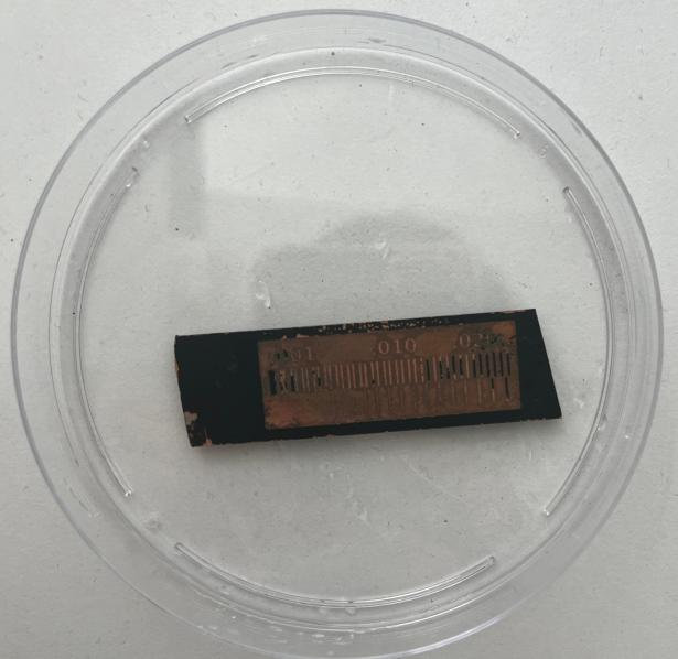
To ensure maximal removal of the paint, and distinct paths, we took a Petri dish, and poured a natural etching solvent.
1 part vinegar
1 part hydrogen peroxide
a pinch of salt
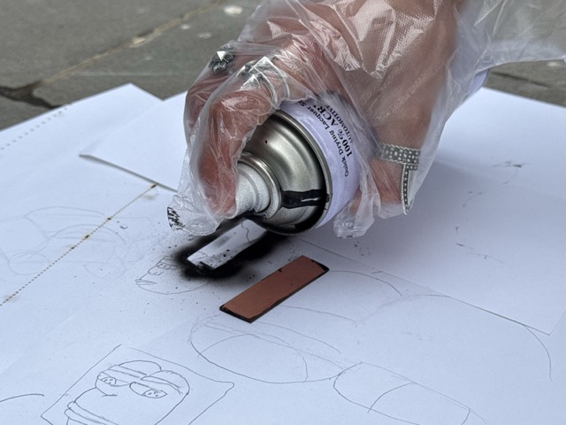
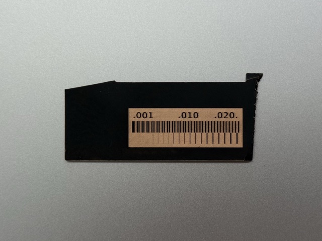
*The measuing beaker [bottom left image above], and the laser etched copper blank [bottom right image above].
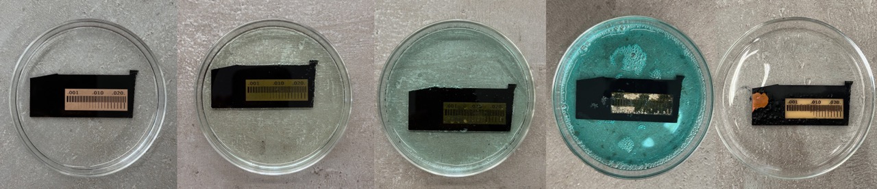
After this we put the etched blank into the solution. The change is depicted in below in 5 steps. The result was still not satisfactory, some of the finer lines ahd been degradated. I assume that this could have been better if we had not left the plate emerged in the solution for so long. But in any case, it was an interest approach.
Initial Fail
In reality, this was our second attemp of the same test. First and most important change was leaving the spray paint dry overnight. The second, we ended up changing the proportion of the ingridients. We decided to make these changes as the first etched PCB had no masked lines left, which would be a failure if it were an operational PCB.
Individual Assignment
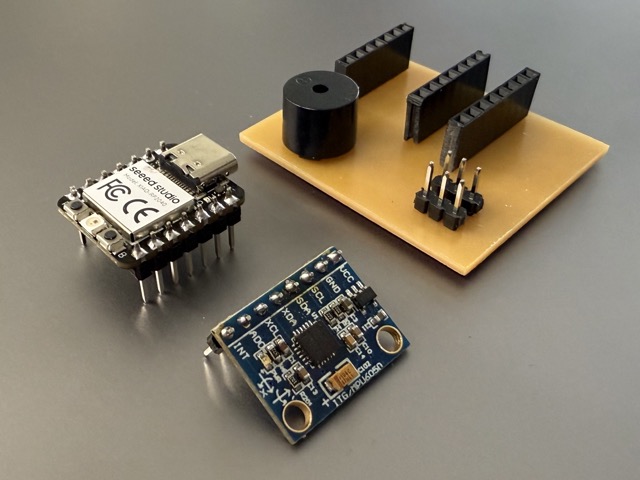
For my final project I am designing a drone rescue parachute.
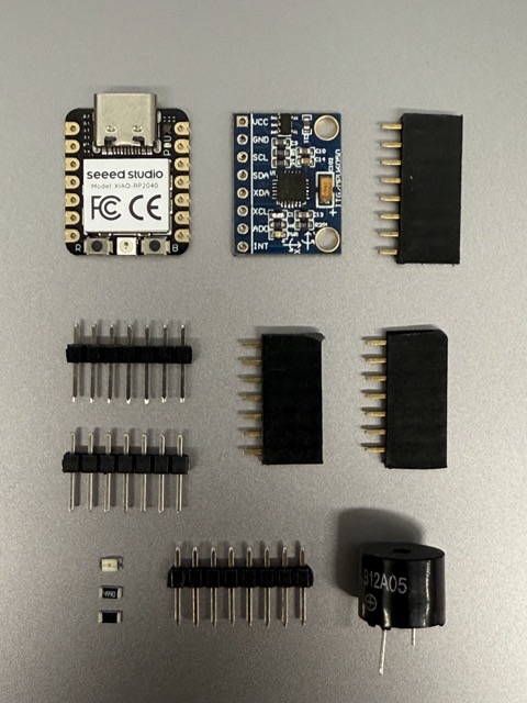
• 1x XIAO RP2040 • 1x GY-521 Accelerometer and Gyroscope • 1x Buzzer • 1x 1206 SMD LED • 1x 0Ω Jumper Resistor • 1x 220Ω Resistor
Step 1: designing
Yet againg we return to KiCAD.
First you open the Schematic Editor, and add the predetermined list of components. When adding these onto the sheet you need to make sure the symbols also come with footprints. If not, you either go online and download the footprints corresponding to your pieces, or create them yourself in Symbol/Footprint Editor [depending on your needs].
Once you have layed out a desired schematic, you switch to PCB Editor, and wire the board according to the pieces.
Schematic editor
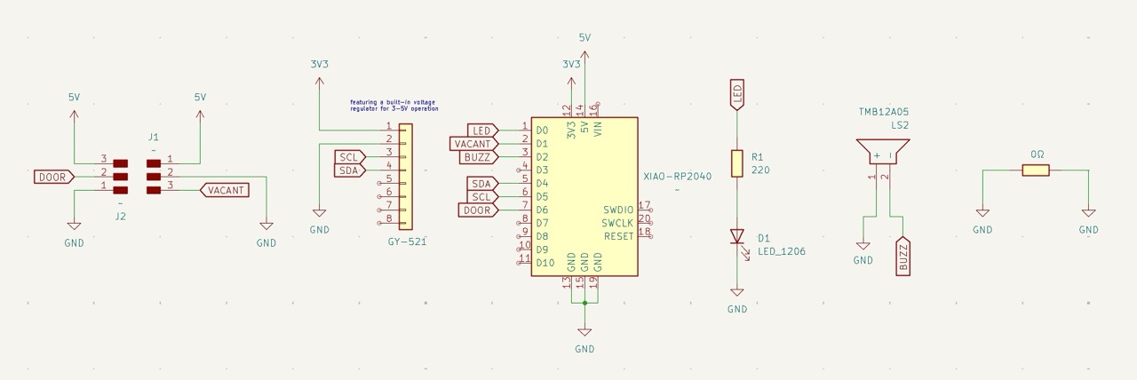
In my example, I did not have a symbol or a footprints for my buzzer. So I googled the name of it online and found the files through this website.
If I were unable to find them online also, my steps would be to measure the distamce between the anode and the cathode and sketch a simple circle with two holes in it. This would serve as the soldering pinholes for the buzzer.
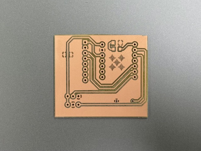
PCB editor
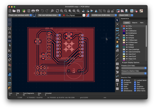
After having every component present in the schematics, I switched to PCB editor. There I placed everything as neatly and tightly as possible. For through-hole components I pressed F to mirror their footprints [footprints indicated in light blue], and flip them upside down in 3D view.
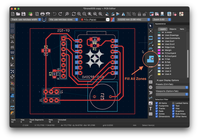
For this PCB I have decided to use the copper surface area as the groud. To mark this in the editor you need to go into blue tool with a dot [shown in the image below], or press B after having the area traced for GND.
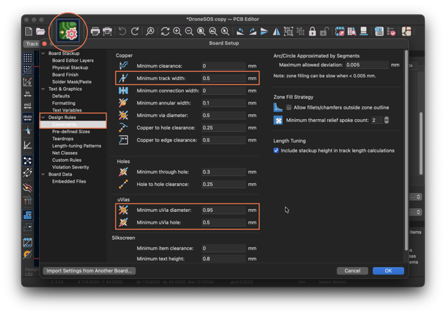
Additionally, in Constraints, under Design Rules I typed in the size of the paths and the through-holes. This comes in handy before you start tracing the connections of the pins, as you do not need to mannualy set the width of each path in the net.
Regardless, if you change this after having everything ready, this could help you find paths that are more narrow than the indicated minimum. For this you need to run the DRC [design rule checker], which goes over the components and checks for errors.
Exporting
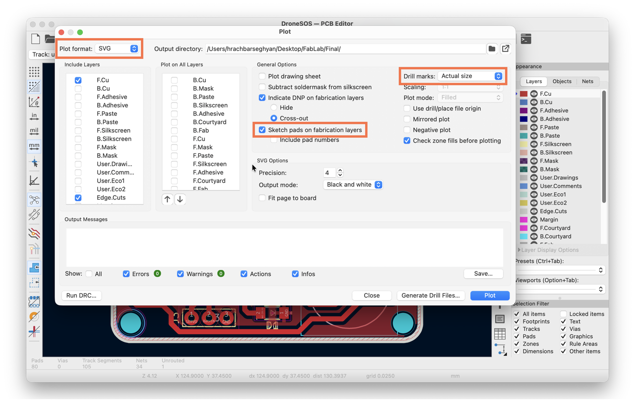
To export the files you should go to: File > Fabrication Output > Gerbers

Then you need to change the default .gbr file to .svg, change the drill marks to actual size, and enable Sketch pads on fabrication layers.
Step 2: G-code
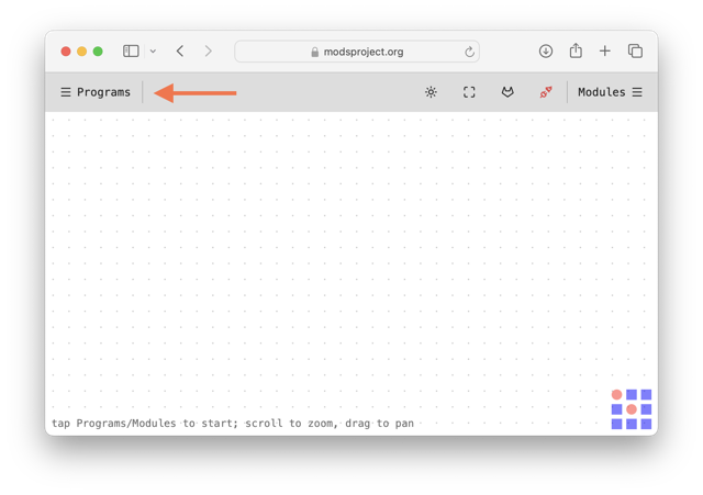
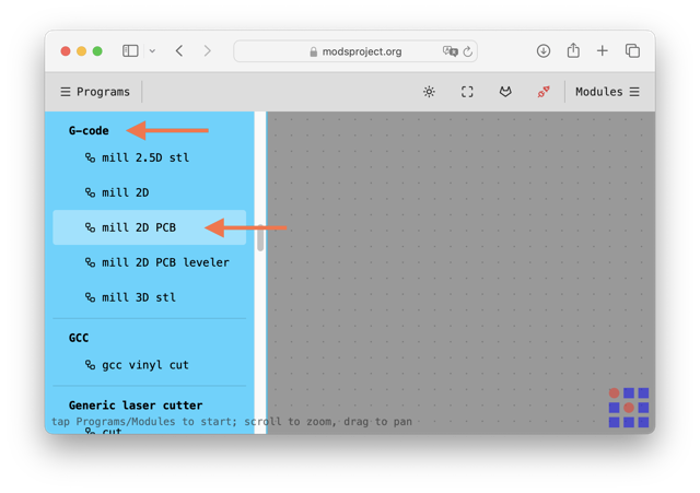
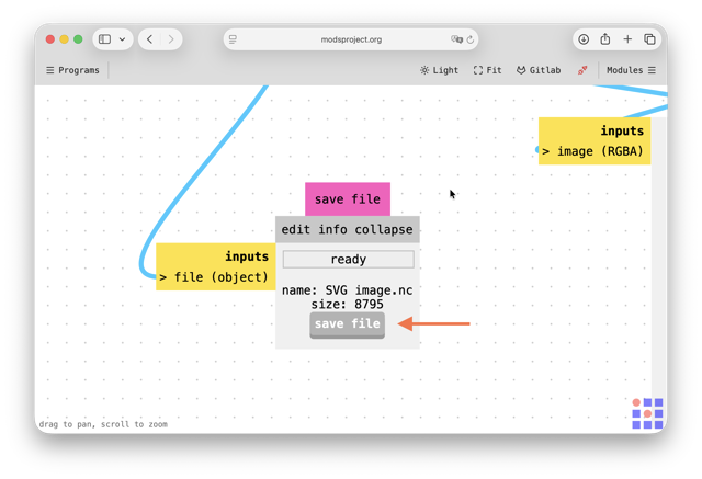
To generate the toolpath for the milling machine go to mods, a web-based CAM. In the top-left corner, under Programs scroll to G-code.
Part 1: tracks
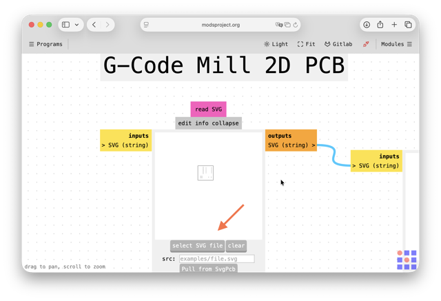
Here you need to select mill 2D PCB [refer to the image below].
A framework will appear, there you need to upload your SVG file [this sould have been exported through KiCad]. Then you invert the image [refer to the steps in the image below]. NOTE: for the edge cuts, you do not invert the .svg file.
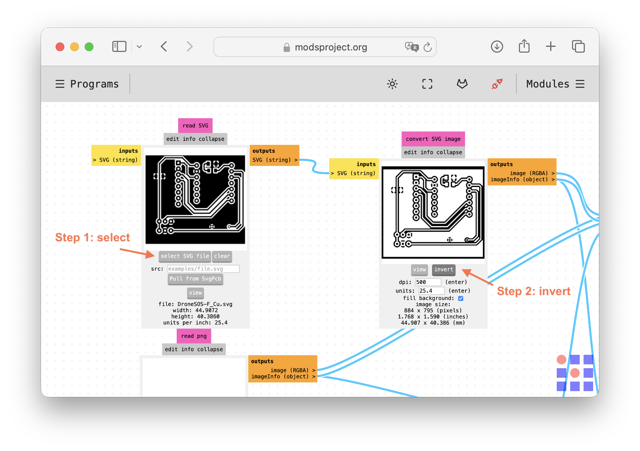
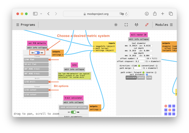
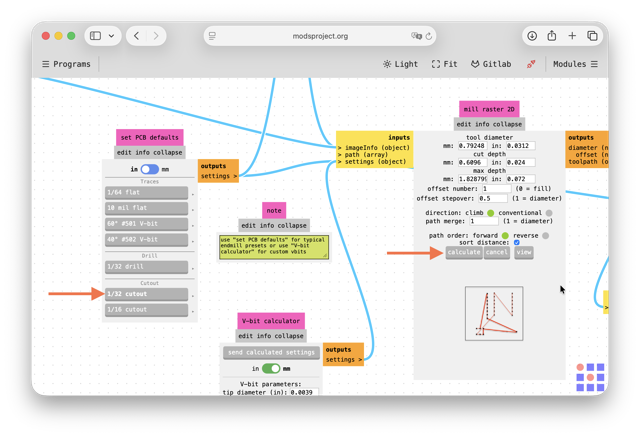
You can toggle between inches and millimeters. For these steps I prefer imperial system, as they are identical to the markings on the drill bits. For traces you choose 1/64 in bit, and for cutouts you should select under Cutout 1/32 in bit.
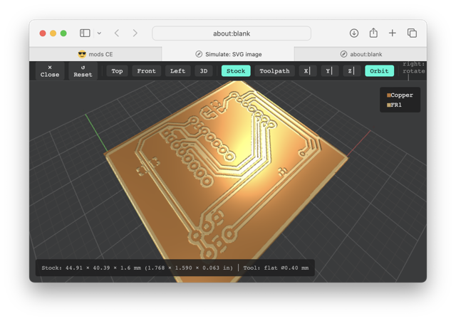
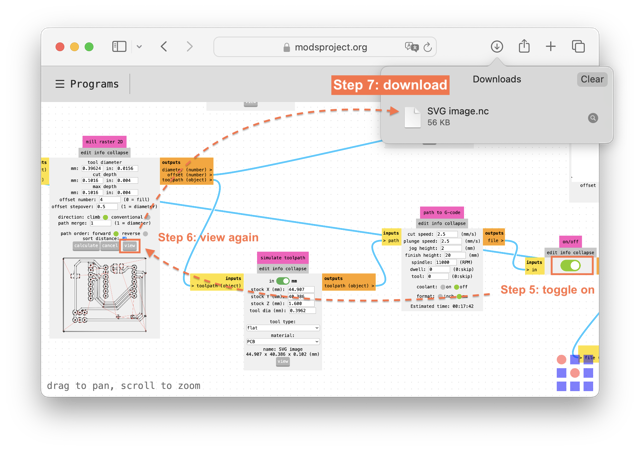
After this, press Calculate and below the path of the bit should appear. Press view and the 3D model will appear in a new tab.
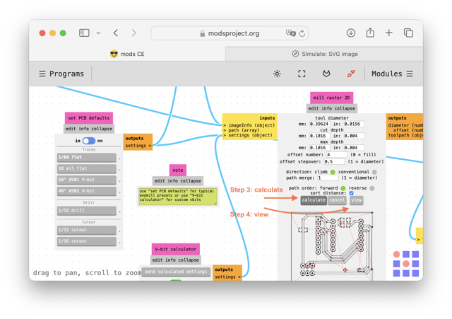
Follow the last 3 steps in the image below: toggle on, press view again, and the .nc file should download.
Part 2: edge cut and holes
I make sure that the size is fine by importing the .svg into Inkscape. The same has been done for the tarcks file as well.
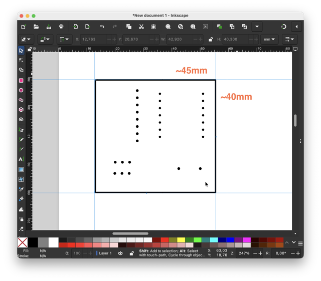
With the tracks and holes we do almost the same operations to generate the G-Code, except this time we do not invert the .svg in mods.
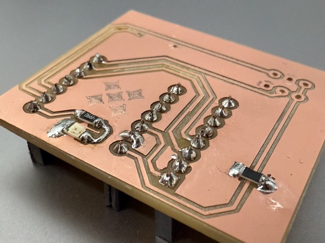
Step 3: milling
I began by attaching an FR-1 PCB blank with double-sided tape onto the machine bed. Then I clamp it down with for about 5 minutes to ensure good adhesion.
Once the .nc files are ready, typically two file, one called F_Cu for the ground wiring, the other called Edge_Cuts for edges and through holes. Once in a while you might also have other layers, i.e. a Silkscreen, to carve text, or logos, but not cut through the copper layer.
I then sent the .nc files to the computer which has the VPanel app connected to the Roland SRM-20. In the interface I level out the X/Y axes, then finally the Z axis. The Z-axis requires one to untie the milling bit, set the zero, and the tighten the milling bit back.
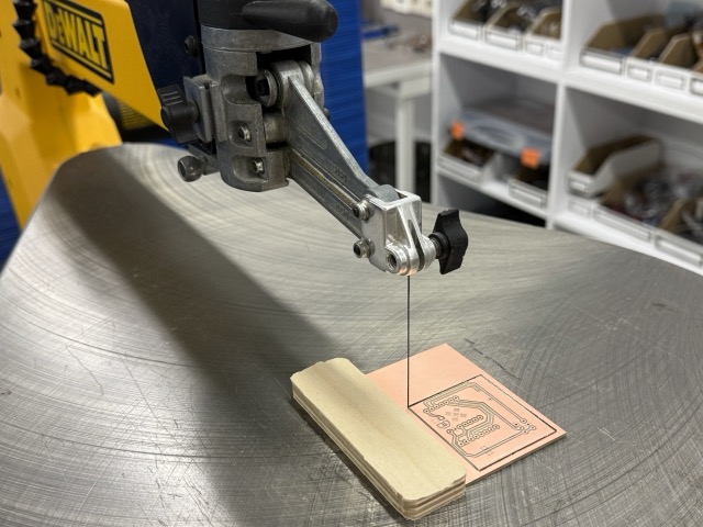
As it did not go according to plan, I went back to the scroll saw, and taped a piece of plywood onto the cutting bed to ensure a straign cut. I wired the steel wire though the copper plate, and cut the 4th edge off.
Step 4: soldering
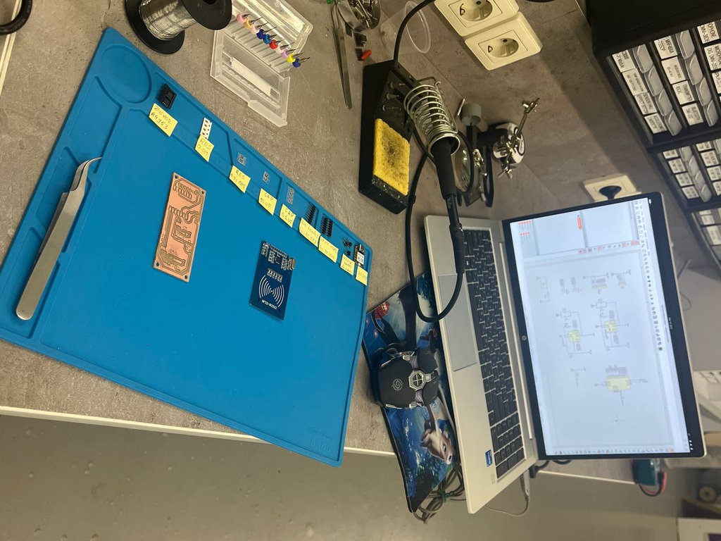 This is what our soldering workbench looks like [photo taken from Mariam Daghbashyan’s page]. I had used a soldering iron, solder, nippers to adjust the pin headers to size, and tweezers to place the parts in their places.
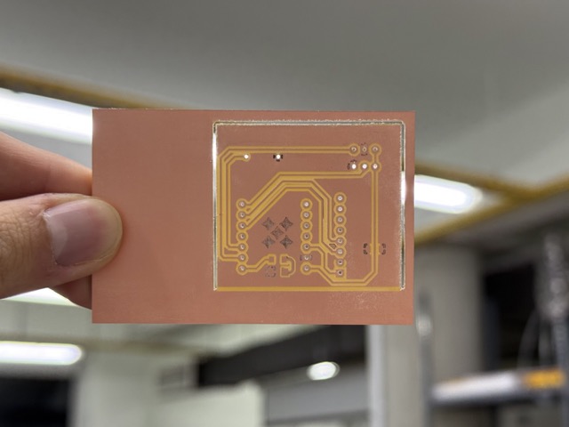
After milling the PCB, I fetched the electronics components to begin soldering.
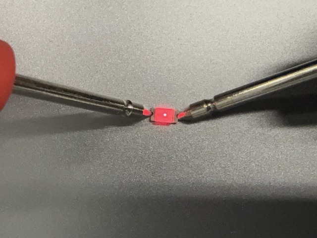 I also took a multimeter to check the anode and the cathode of the SMD LED.
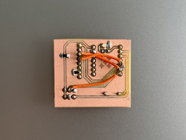
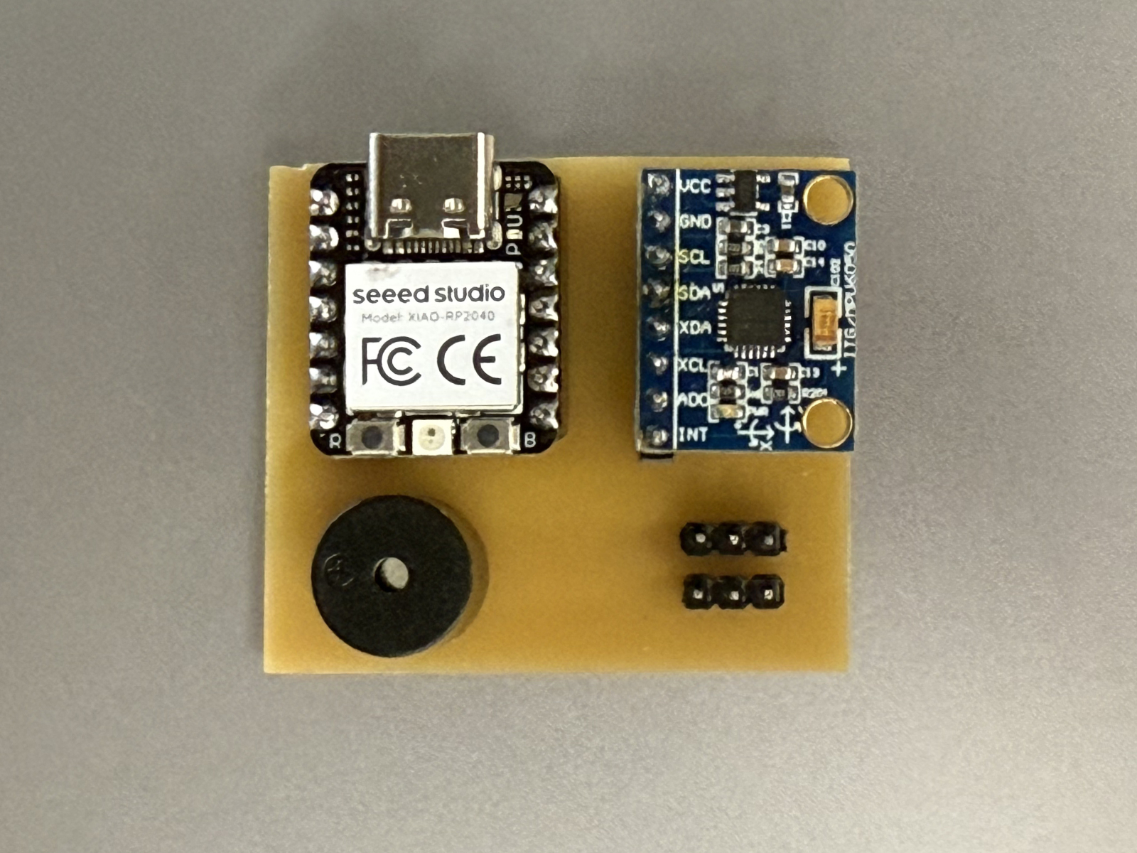
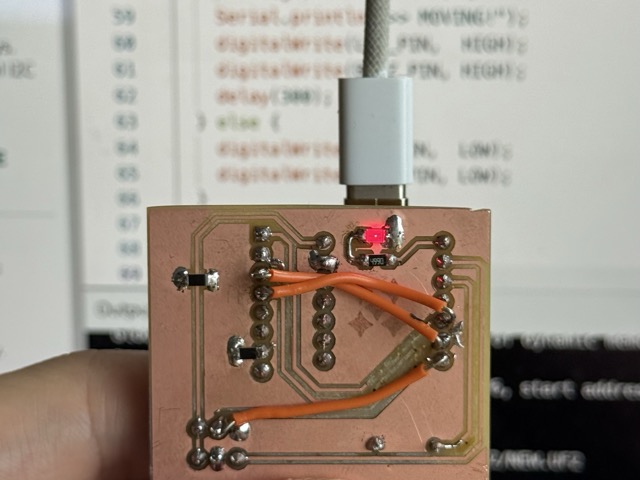
Finally, after having everything in their places, the results looked like this:
LED
To test the connectivity of the LED, I wrote a simple code blinking the LED every half a second.
C++

// Define the pin connected to the LED
const int ledPin = D0;

void setup() {
  // Initialize the D0 pin as an output
  pinMode(ledPin, OUTPUT);
}

void loop() {
  digitalWrite(ledPin, HIGH);  // Turn the LED ON
  delay(500);                 // Wait for 1 second
  digitalWrite(ledPin, LOW);   // Turn the LED OFF
  delay(500);                 // Wait for 1 second
}
The code
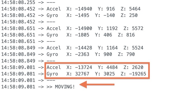
To make sure I have life in this PCB, I wrote a simple code to make the SMD LED blink, and the buzzer tweet. But then after, I asked Claude.ai to generate code based on the MPU6050 library, which would also take in account the gyroscope.
I then found this website with some documentation on how to wire the gyroscope with the RP2040. The code did not use the library I had, which was MPU5060.
I asked chatGPT to take the minimal code I had, and connect it to the reference code above, yet using the functions found in my downloaded library.
C++

#include <Wire.h>
#include <MPU6050.h>

#define LED_PIN  D0
#define BUZZ_PIN D2
#define THRESHOLD 5000

MPU6050 mpu;

void setup() {
  Serial.begin(115200);
  while (!Serial);

  pinMode(LED_PIN,  OUTPUT);
  pinMode(BUZZ_PIN, OUTPUT);

  // Startup blink/beep
  digitalWrite(LED_PIN,  HIGH);
  digitalWrite(BUZZ_PIN, HIGH);
  delay(500);
  digitalWrite(LED_PIN,  LOW);
  digitalWrite(BUZZ_PIN, LOW);

  Wire.begin();
  mpu.initialize();

  if (!mpu.testConnection()) {
    Serial.println("MPU6050 not found! Check wiring.");
    // Rapid blink = error
    while (1) {
      digitalWrite(LED_PIN, HIGH);
      delay(100);
      digitalWrite(LED_PIN, LOW);
      delay(100);
    }
  }

  Serial.println("MPU6050 Found!");
}

void loop() {
  int16_t ax, ay, az;
  int16_t gx, gy, gz;

  mpu.getMotion6(&ax, &ay, &az, &gx, &gy, &gz);

  Serial.print("Accel  X: "); Serial.print(ax);
  Serial.print("  Y: ");      Serial.print(ay);
  Serial.print("  Z: ");      Serial.println(az);

  Serial.print("Gyro   X: "); Serial.print(gx);
  Serial.print("  Y: ");      Serial.print(gy);
  Serial.print("  Z: ");      Serial.println(gz);
  Serial.println("---");

  if (abs(gx) > THRESHOLD ||
      abs(gy) > THRESHOLD ||
      abs(gz) > THRESHOLD) {
    Serial.println(">> MOVING!");
    digitalWrite(LED_PIN,  HIGH);
    digitalWrite(BUZZ_PIN, HIGH);
    delay(300);
  } else {
    digitalWrite(LED_PIN,  LOW);
    digitalWrite(BUZZ_PIN, LOW);
  }

  delay(200);
}
*Prompt8.2
Problems
The first problem was the incorrect of the toolpath generation, please scroll up to Step 3: milling to read more.
The second problem: things seemed to be worse than I thought they’d be. I quite liked my fisrt-time soldering reults, but soon after found out that some pins were placed incorrectly, to be precise SDL and SCL.
Also, on my GY-521 [gyroscope and accelerometer], I disregarded the ADO pin, which was supposed to be connected to GND for this purpose. Therefore after I had already milled the FR-1, I was advized by my local instructoir Onik, to bridge the ADO pin with a 10kΩ resistor.
Conclusion
This week, as always, very interesting. I loved working with a more precise CNC machine, and I love how my paradigm had shifted, and form now on I will never look at PCBs the same.
Resources
Prompts
Prompt8.1 Please visualize an FR-1 with a copper blank, and a PCB milling machine. It should take away the copper layer, leaving the backing to created isolated paths.
Prompt8.2 Write a simple C++ script for an RP2040 that blinks an LED on pin D0 and beeps a buzzer on D2 when the MPU6050 gyro senses a lot of movement. Please make sure the code won’t freeze if the board is powered by a battery instead of plugged into a computer. If the gyro chip isn’t wired right or can’t be found, make the LED blink super fast continuously so I know there is an error. Finally, add placeholders where I can easily type in my specific I2C pins, and make the LED and buzzer trigger whenever the gyro readings pass a threshold of 5000.