Week 15: System Integration
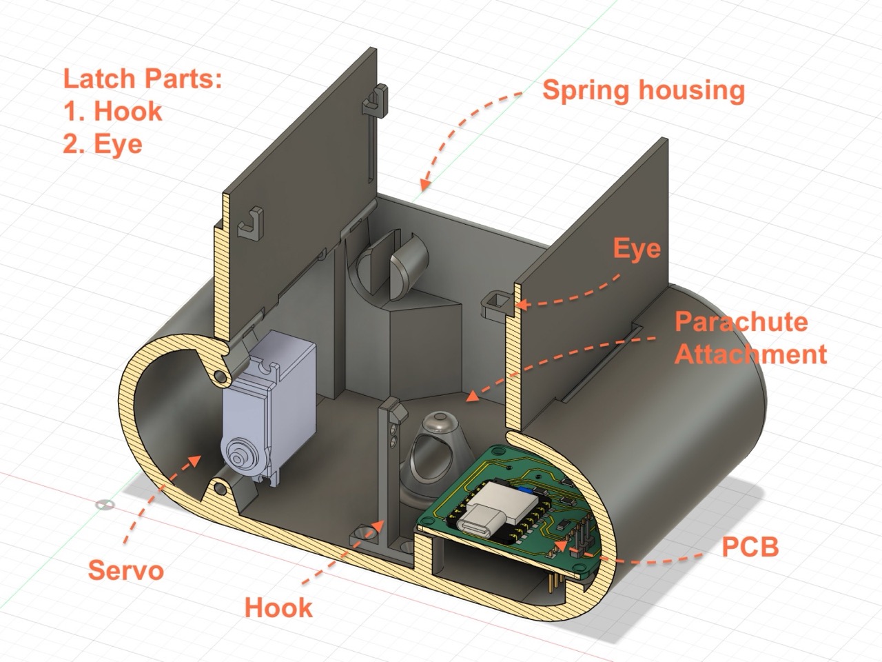
As I had spent significant time on sketching, and design thinking, so I though I would dedicte a chunk from this week to explaining those design decisions.
Design Choices
Despite Fusion offering a timeline where you can change features and dimensions, I did not want to commit changes on my main models. I had concerns that things could have gone in wrong directions, and I would need to redo the models from scratch. Indeed, I had ended up making 3 of the complete model of the device, as I could not change some features efficiently. So remaking a complete new CAD model was more time friendly [or I haven’t discovered good practices of CAD modeling yet].
The Hinges
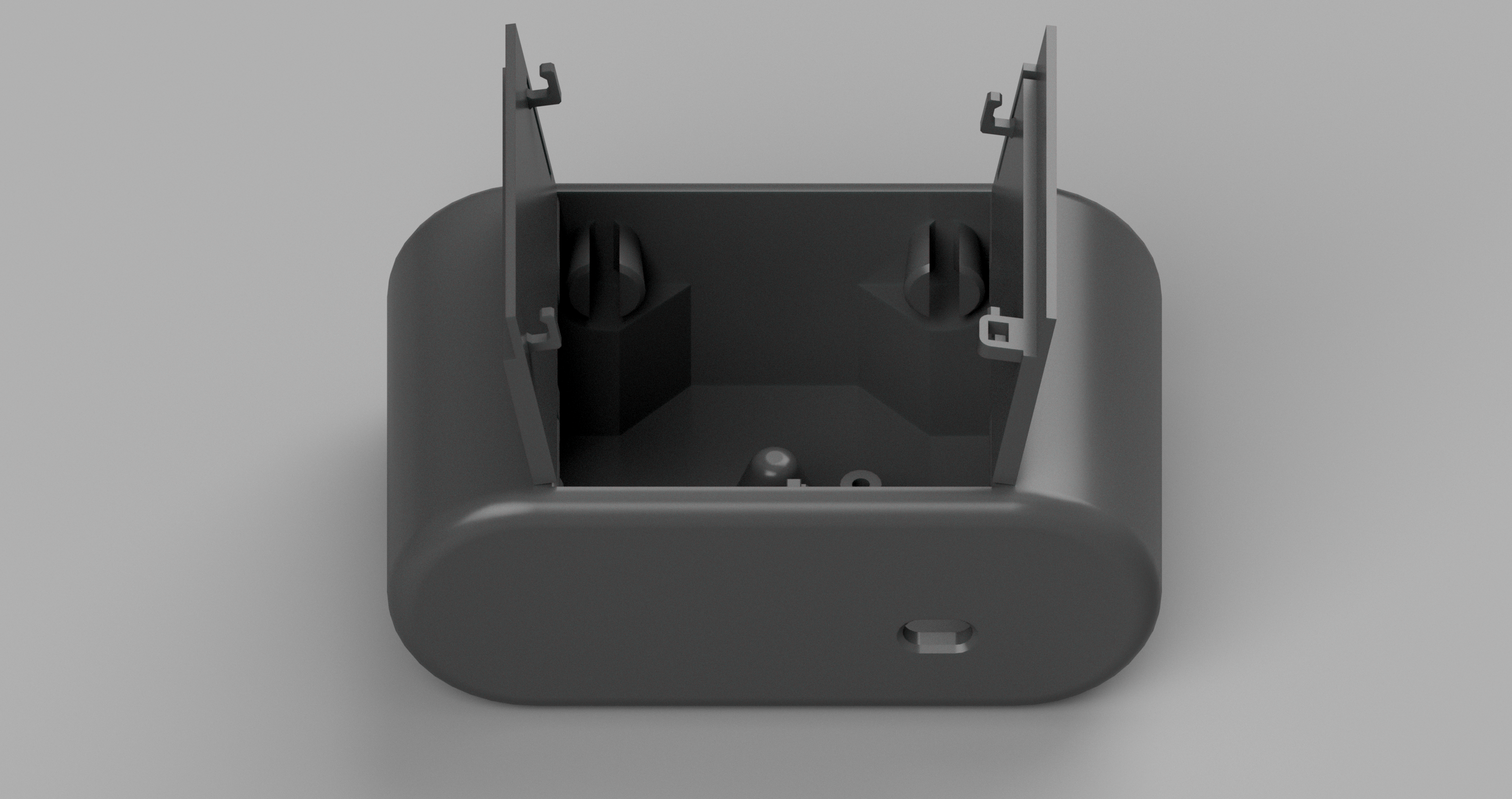
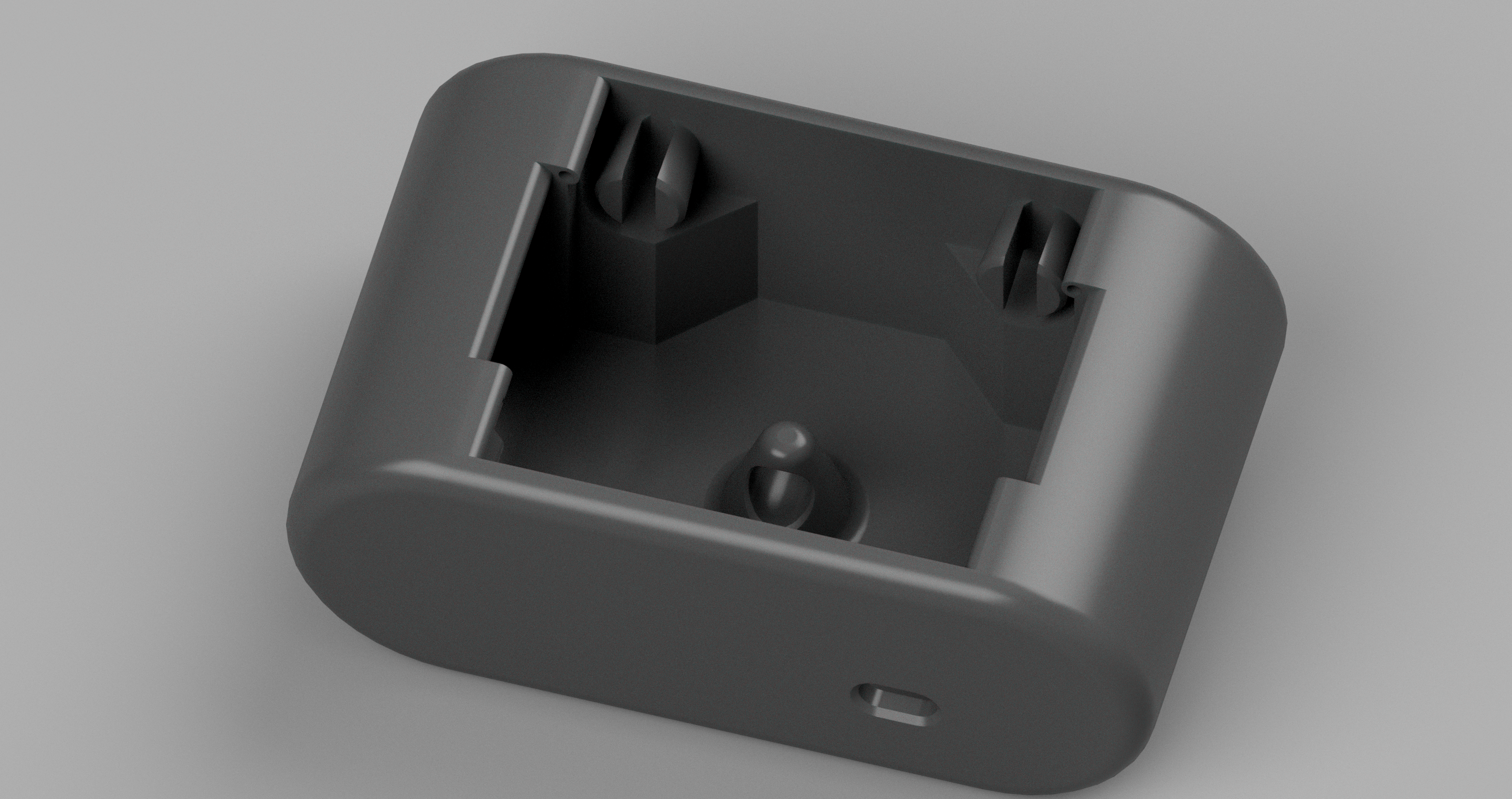
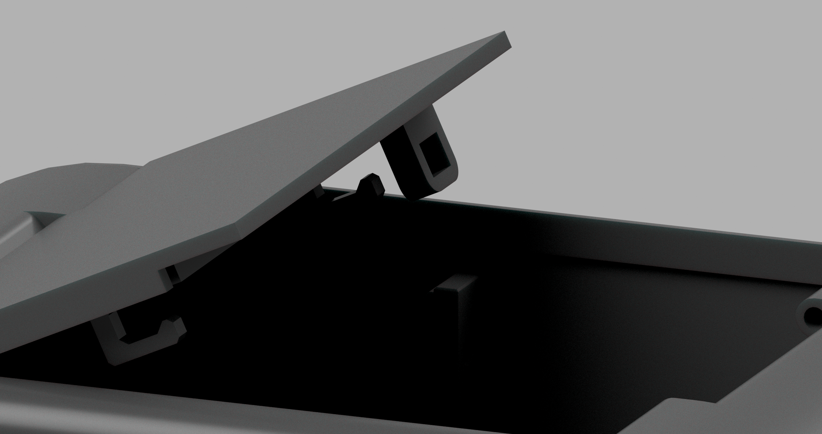
I first began experimenting with the hinge designs, and whether they would open beyond 90 degrees. Not to damage the main file I first opened a new draft file on Fusion to understand the measurements. After all, the doors were one of the key features of the case.
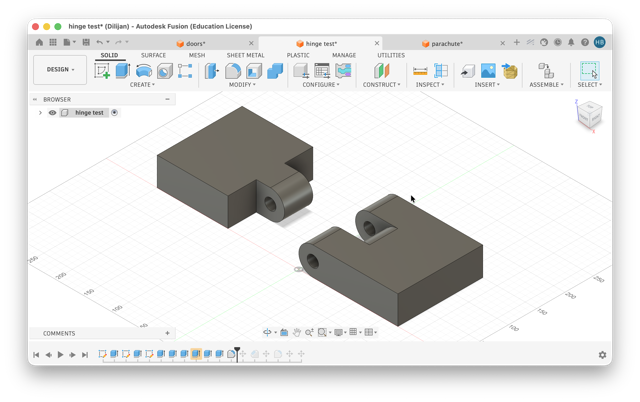
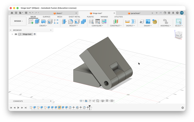
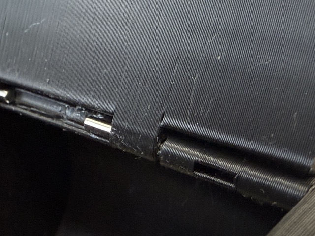 Once I had the final design for hinges, after one more iteration I made a small adjustment – a slit to push out the rods keeping the doors in place.
Failed Results
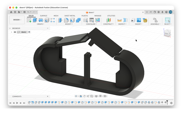
In reality, I first thought that a print-in-place door would be a good idea. I did not take into account that fact that these hinges are very small and detailed, and so an in-place print was a bad idea. Mid-testing I got concerned that the springs might even dislocate the doors, even though their presence post-deployment is not critical.
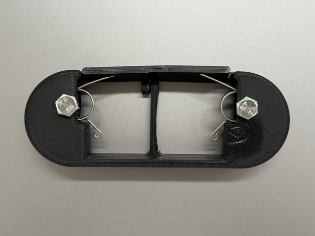
To keep the springs inside their housing, I drilled a hole using a hand drill and secured them with a bolt and nut, as shown in the right image below.
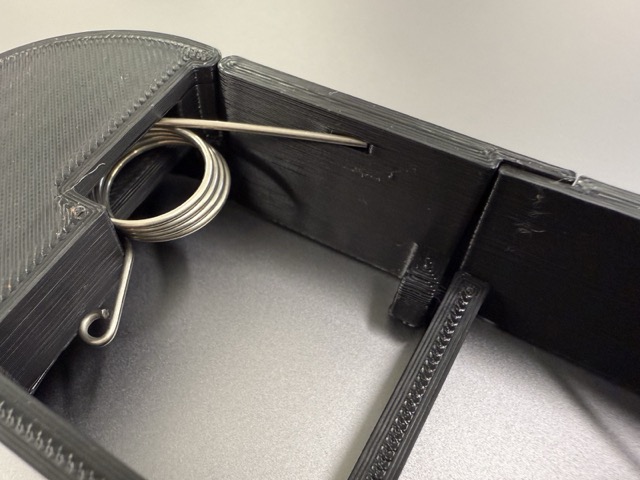
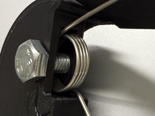
While this setup was not the prettiest, it was good enough to quickly test and iterate on the design.
The Springs
The inverse cones with slits letting the springs slide in and not out. On the doors’ undersides I also added a “railing” for the springs looped ends.
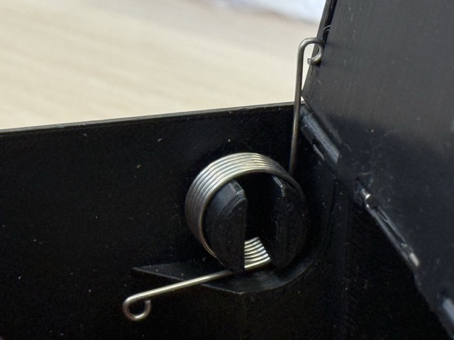
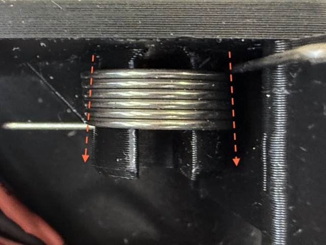
Initial Feature
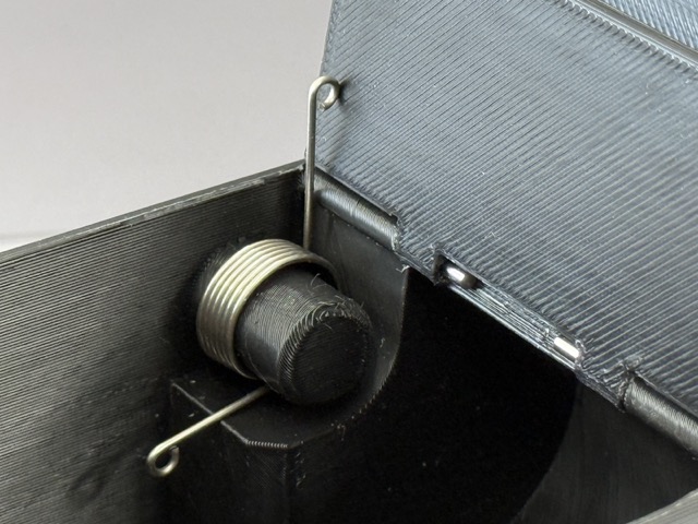 In the right image the knob “holds” the spring in place. In reality I knew that this would not have functioned well, but I simply wanted to test how the sping would behave when supressed. Once I had taken these measurements, I designed a invers cone-like shape, which would not let the springs slide out.
The Latch
I colored the model in three colors to differenciate the individual objects. Red is the main body, yellow is the top door with the lever eye [this also holds the bottom door in place], and in grey is the hooked lever with two holes connected to the servo.
Why is the lever separate and not printed?
To begin with, I prefer printing the case in a sideways orientation, where here the print direction badly reflects on the lever. Moreover, if the lever gets damaged, I simply cannot replace it. Nevertheless, if the siffness is not optimal for the servo’s pull, I cannot waste a whole case – 150 g of filament, and ~10 hrs goes to waste.
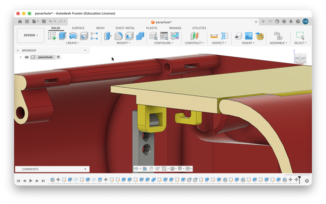
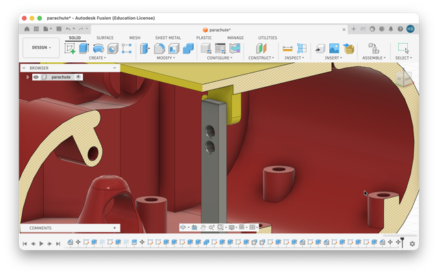
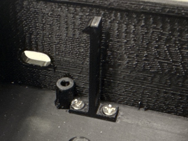
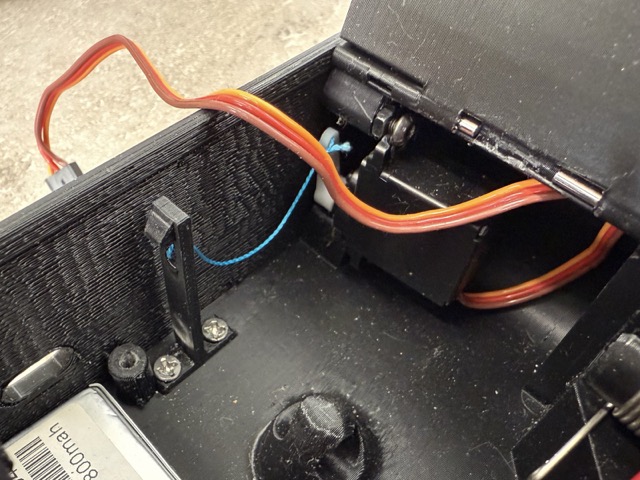
In this image below you can see how the lever is screwed into the case.
The Parachute
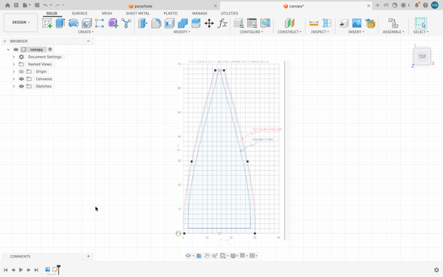
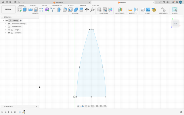
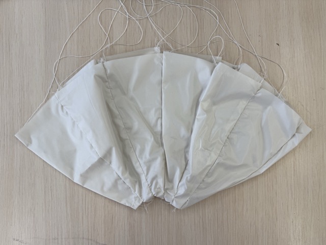
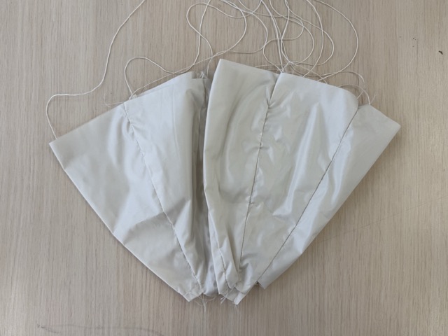
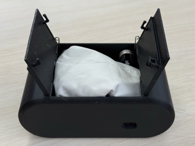
I had taken a photo from online and traced the individual patel of the canopy design, the I laser cut it using a thin nylon fabric. After I sewed 13 petals together.
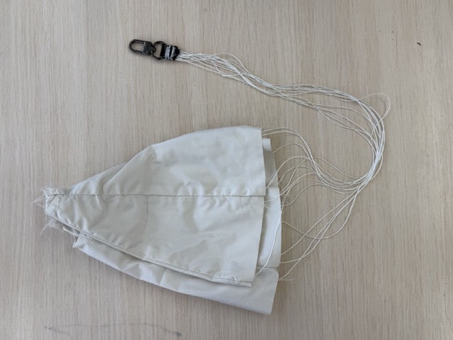
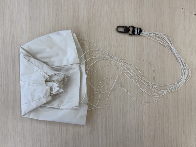
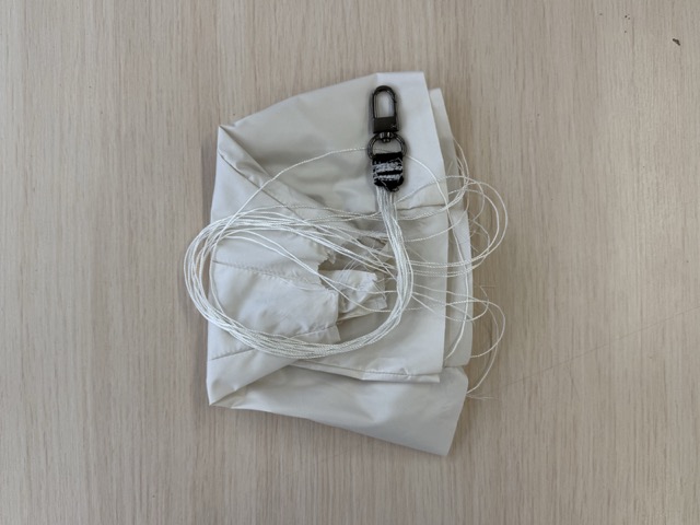
Parachute Folding
Parachute Loop
As I wanted a unibody design, but a detachable parachute, I needed a loop that would attach the parachute to. But i could not simply be a loop, because the moment the parachute deplys there is a lot of pull tension on it. So when slicing I added a modifier to change the infill density.
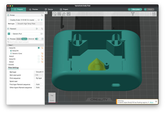
Now, inside the case there is a cone-like infill which acts like a root system, connected more securily to the whole body. You can see the embedded structure in the video below.
Electronics System
For the project I will be using a XIAO ESP32 C3, Gyro & Accelerometer MPU6050, a passive 5V buzzer, a switch button, a LiPo 800 mAh 3.7V battery, a servo motor and SMD LED.
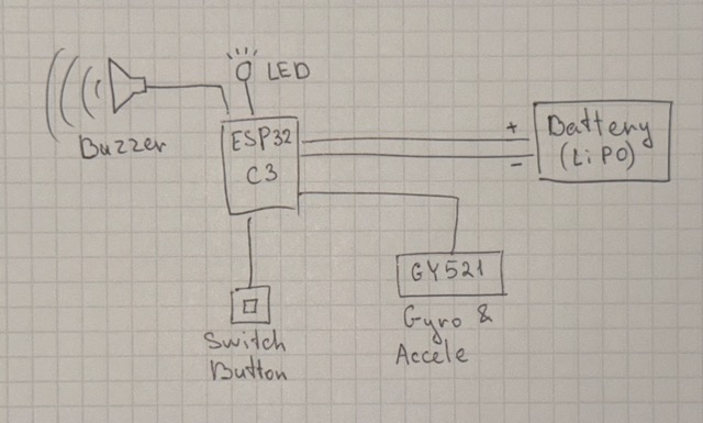
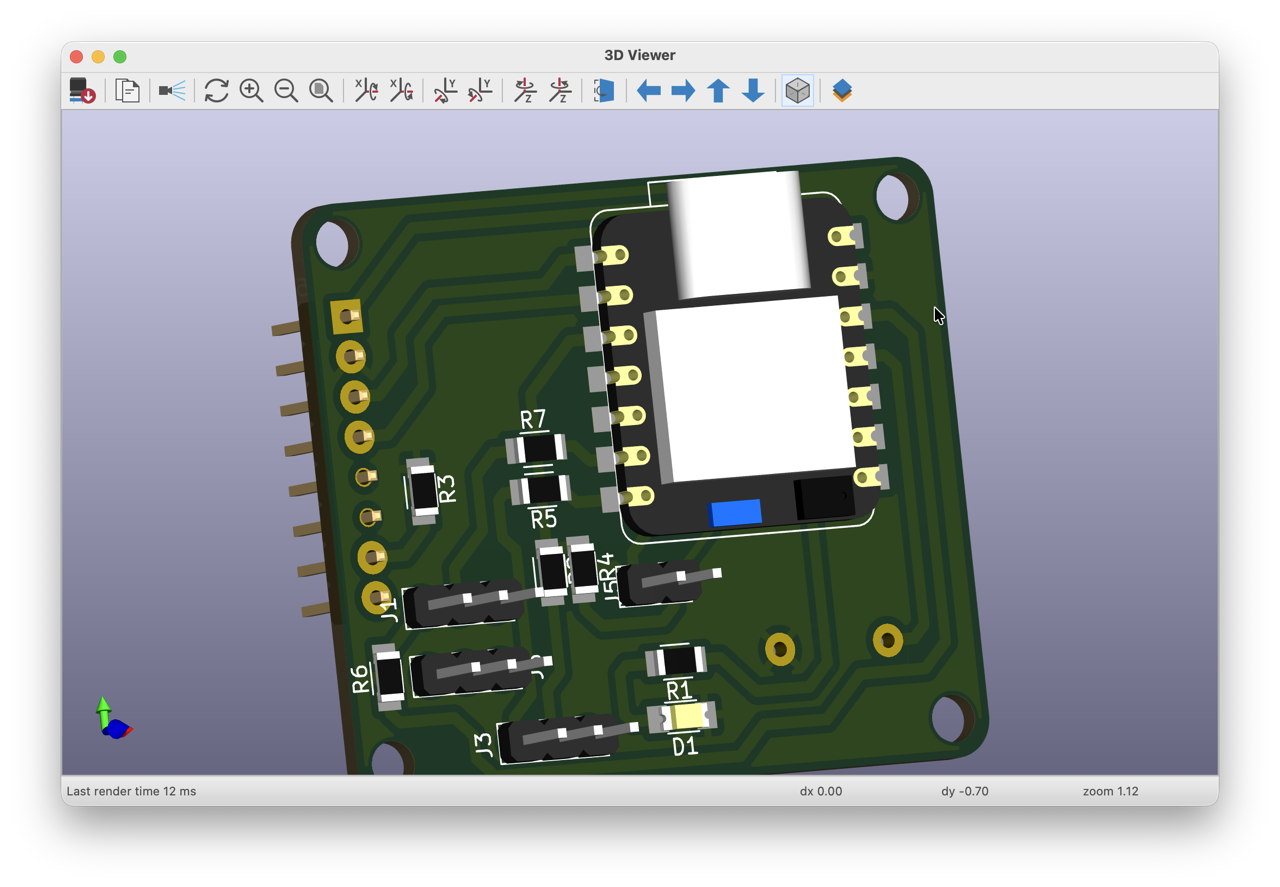
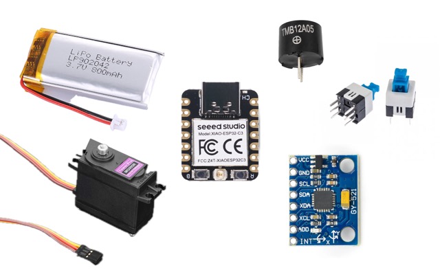
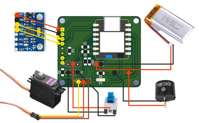
The buzzer, the switch, and the accelerometer will be attached onto the PCB by soldering using througholes and pin headers.
Servo Integration
In the case design I left some space for the servo’s arm to rotate freely, and for this I designed some holes to also screw the servo in.
The servo has a set of prebuilt wires with female pinholes, for this I soldered compatible male pin headers onto the PCB. The wires are Brown [for GND], Red [for volage], and Yellow [for data].
Power System
The whole circuit is powered from a single 800mAh LiPo battery. Power distribution runs through the XIAO ESP32C3’s BAT+ and BAT- pins on the PCB — from there it feeds the servo, LED, buzzer, and the GY-521 [MPU6050], as well as the XIAO itself. So rather than routing separate power lines to each component, everything taps off the same rail that the XIAO regulates and distributes.
I didn’t use a separate BMS chip because the XIAO ESP32C3 has a built-in single-cell LiPo charge/protection circuit on board, which is sufficient for a simple single-cell setup like this — it handles charging and basic protection without needing extra components on the PCB.
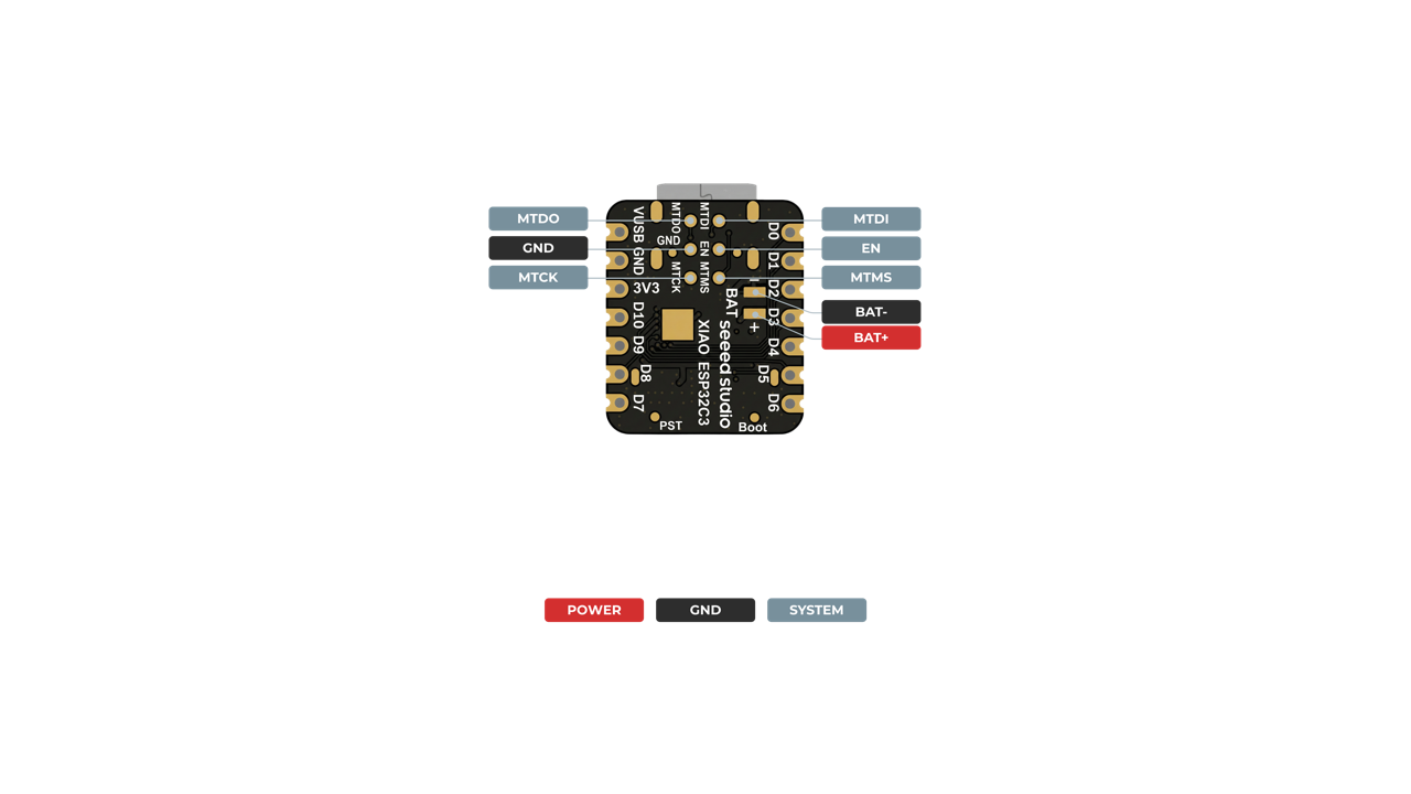
*Seeed Studio Wiki
Battery Integration
The battery connects to the XIAO’s onboard battery input, and charges via its USB-C port. One limitation: the board runs on either USB or battery, not both at once. So during testing, I had to unplug one to use the other [e.g., unplugging the battery when I needed USB for serial monitoring].
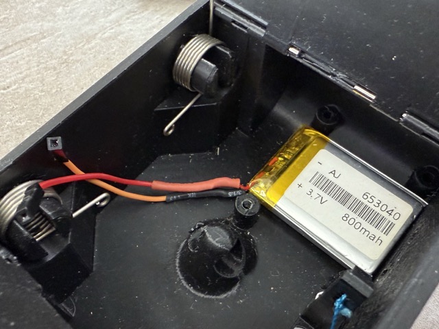
For the battery, I will use a 2.54mm-2P pitch [pin/hole] JST XH 2 pin micro connector which are sturdy, and will not loose easily. This comes factory built with the battery. I might have to extend the wires.
Nevertheless, in my case design I lefted the PCB both to be attached with screws, and left some spacing for the battery to be tucked underneath [I also plan on using a double sided tape to secure it in place].
Conclusion
Overall I am very satisfied with what I had achieved in this design. I am a person who does not like praising myself, but I like the directions I had taken, and the ideas I had come up with to have functional parts. Based on this I am counting on a good learning curve for my CAD skills.