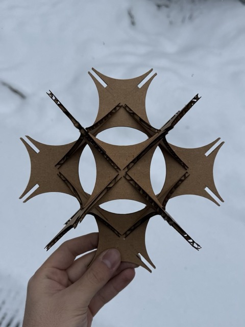
Week 3: Computer-Controlled Cutting
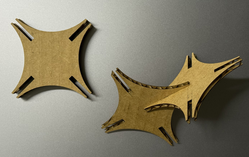
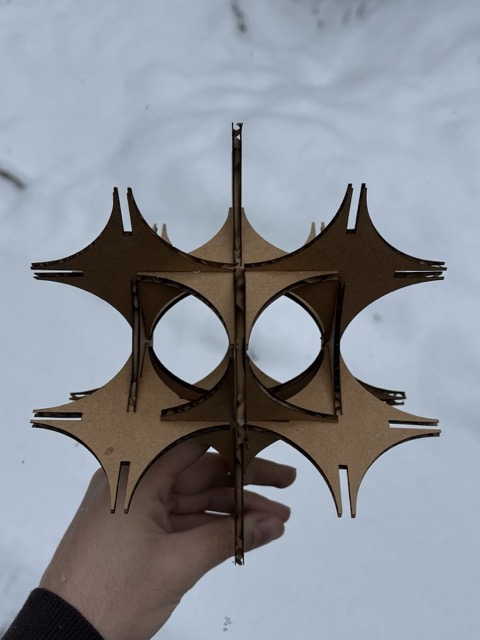
*The individual pieces of the parametric kit.
Group Assignment
Laser Cutter
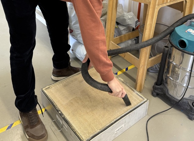
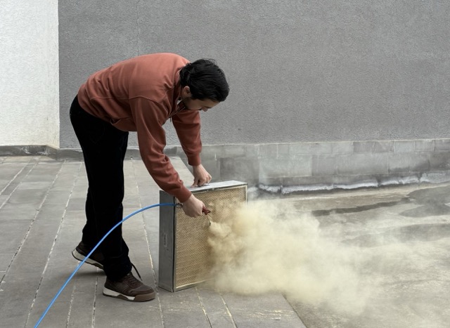
Before getting down to the group assignment we began with servicing, maintenance and chores. First we vacuumed the laser bed, and the chamber. Then vacuumed the airfilter, and cleaned it with pressurized air. After reinstalling the air filter, we proceeded to cleaning the laser beam directing mirrors. For this we used a special solvant, and cotton swabs.
This was our first interaction with the lab’s machinery. The rules and operating steps were clear, and with our instructor’s supervision, everything seemed straightforward. However, once we were on our own, things became confusing quite rapidly. Despite the initial struggle, it was a great experience as we got to mess with the machine without breaking anything, and from then on, everything clicked!
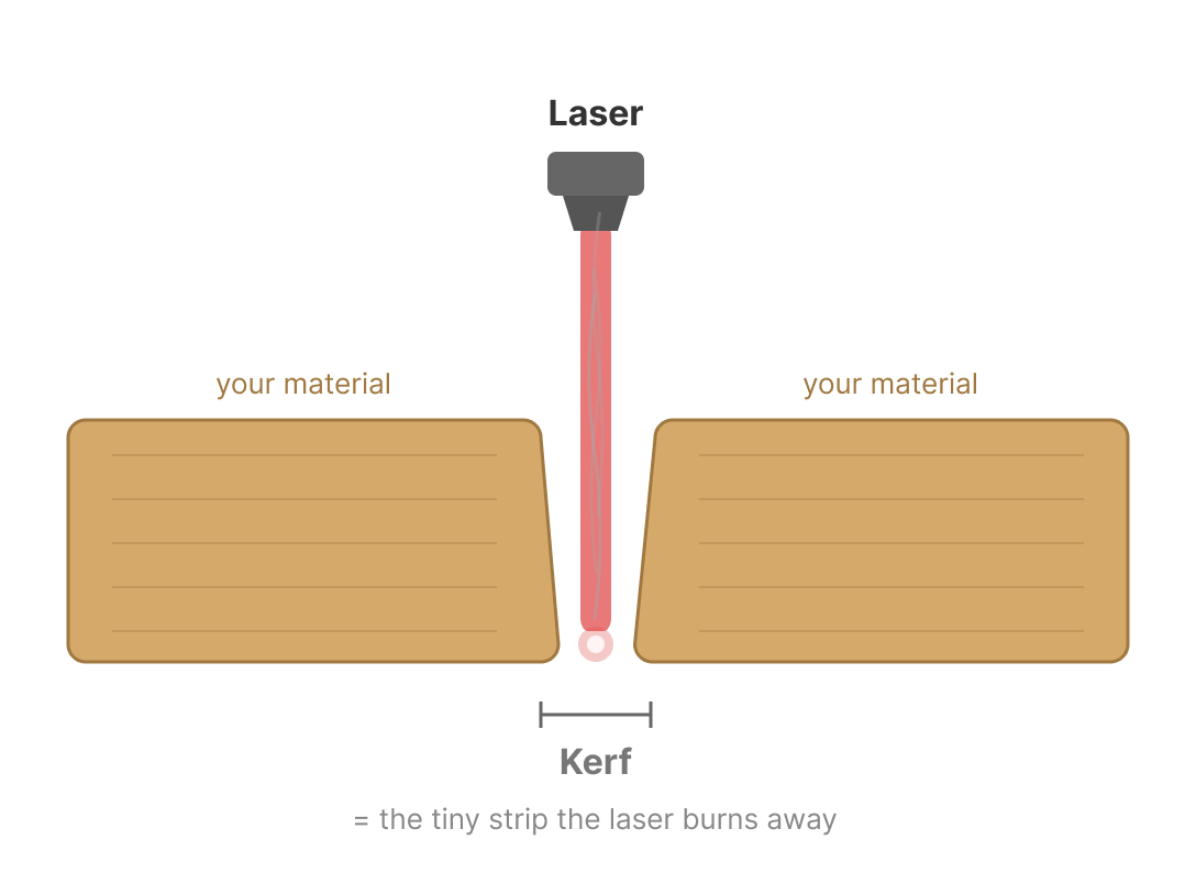
What is kerf?
In fact with lasers, the cut out shape is slightly wider at the top, making it V-shaped, rather than a straight cut.
 *Prompt3.1
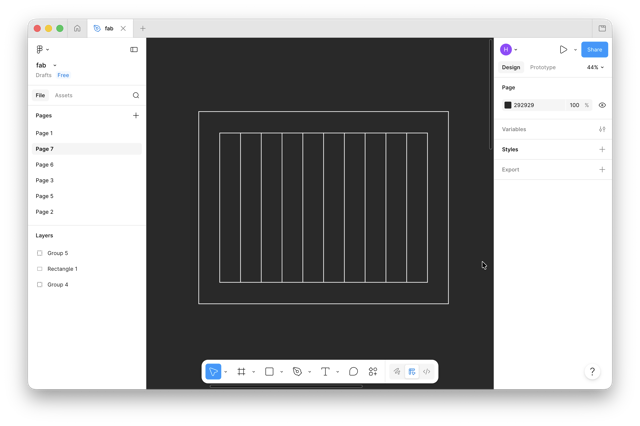
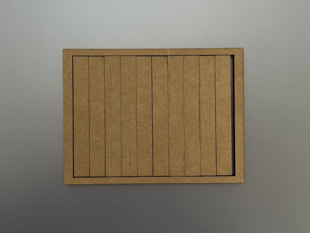
I used a method which I looked up on, then student now instructor, Maxime Richard’s documentation. So, I proceeded with creating 10 small rectangles inserted in a larger frame.
Plywood

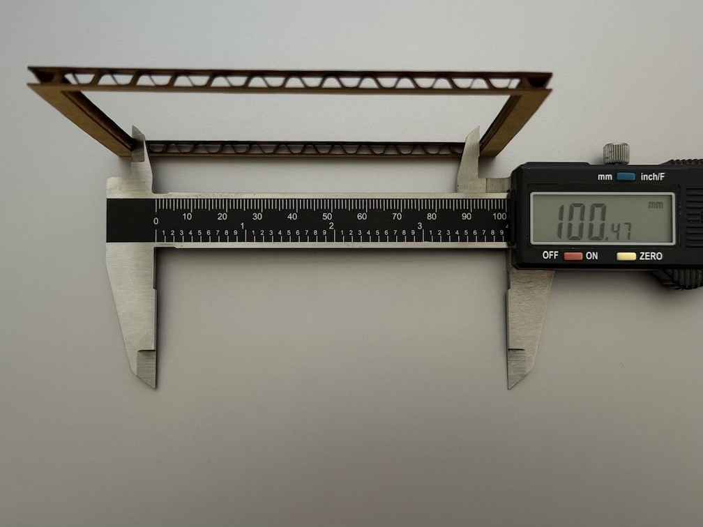
To measuring the kerf, I first tried cutting a 3mm plywood, and to calculate the kerf we proceeded with the following equation:
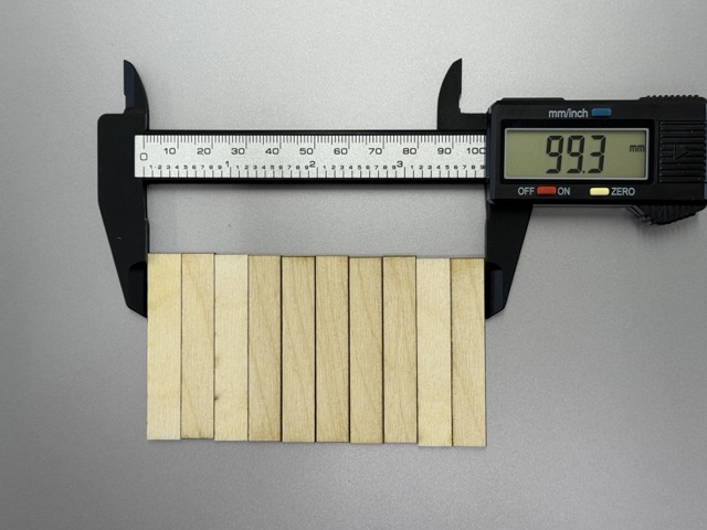
kerf = 0,(09)
Cardboard
The same I attempted with 4mm cardboard, same 10 rectangles inside a frame.
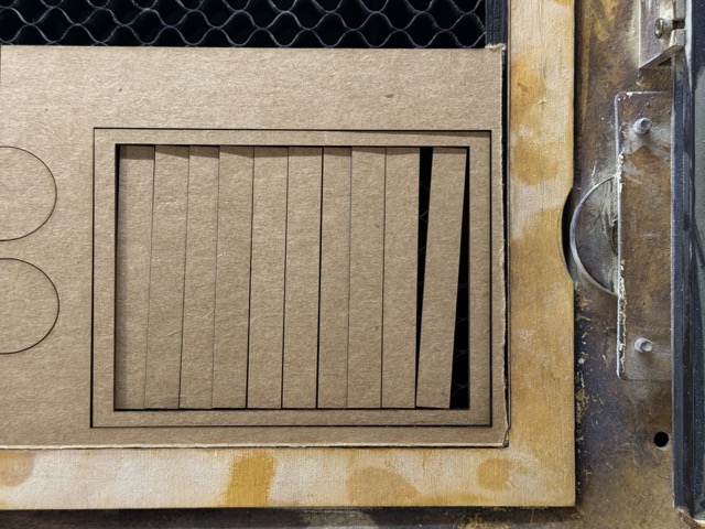
Note: cardboard can deform if not stored properly. Parts under more pressure will be squished and become thinner. This can result in nonuniform pieces.
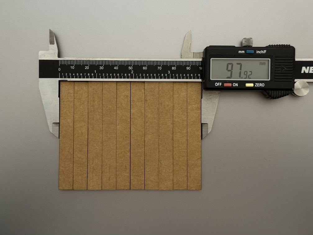
kerf = 0,23
One takeaway we made is that with cardboard the laser burns more material than it does with plywood, whereas the soot accumulated on the edges leaves subtle marks.
Individual Assignment
Parametric Construction Kit
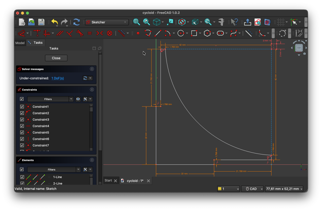
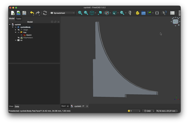
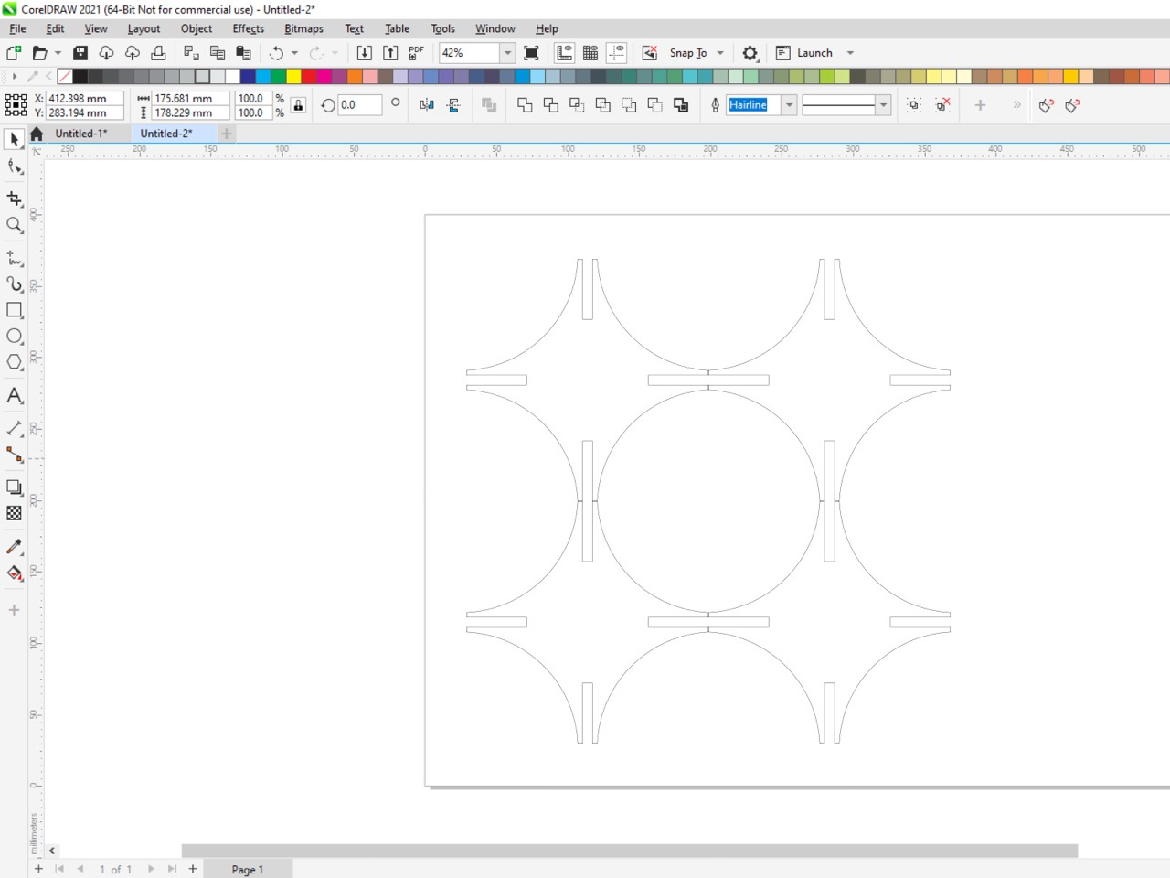
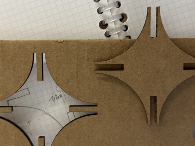
For the construction kit, I came up with a design of two mirrored circle segments, subtracted from a quarter circle, otherwise known as a cycloid. Then the 90° curve was rotated around the origin 4 times to obtain the star-like shape.
I first sketched on paper, cut the shapes out and assembled, then created a non-parametric draft of the shape in 3D, and after took the measurements into the spreadsheet. Finally, after having the measurements, I went back to sketch mode, and assigned their parametric values.
During our local lectures when we were first covering computer-aided design, our instructor Rudolf Igityan made sure we assigned intuitive names to our variables when working with parametric files. This is a good practice both for the designer to pick up months later, and still have understanding what the variables are, and also for sharing files with other people. I find this much more important when working in cloud based CAD applications such as Fusion 360, where multiple contibutors can work on the same project together.
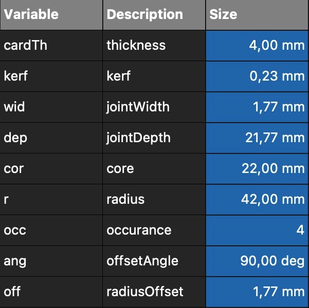 Hence, in the left table you can see listed variable names with their descriptions. While from the first glance the names might not give away much, the advandtage is that these are short. And though the descriptions could have been lengthened to sentences, like comment blocks when coding, this seemed to be the best approach for me.
Right-click on a cell > Porperties > Display Unit > Alias
For the kerf in this kit I used the following equation:
&
jointDepth = (22mm - (Kerf/2))
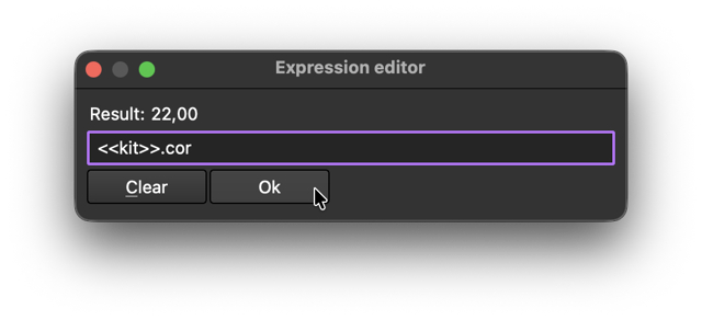
Once you start sketching, you can right then and there assign all the values by pressing D to give dimention, then click the cricle with f(x), and type in <<tableName>>.variableName.
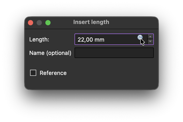
NOTE: wrting 10mm, even though it could be equal to the variable value, it would not be equivalent to having the variable assigned.
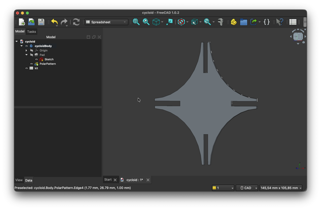
 Once I had obtained one of the petal I revolved it around a single axis using the polar pattern tool. As the pattel has a right angle, all I needed to do was t marke inidvidual polar curve to have a 90° angle, and assign 4 repetitions to obtain a full-circle revolution.
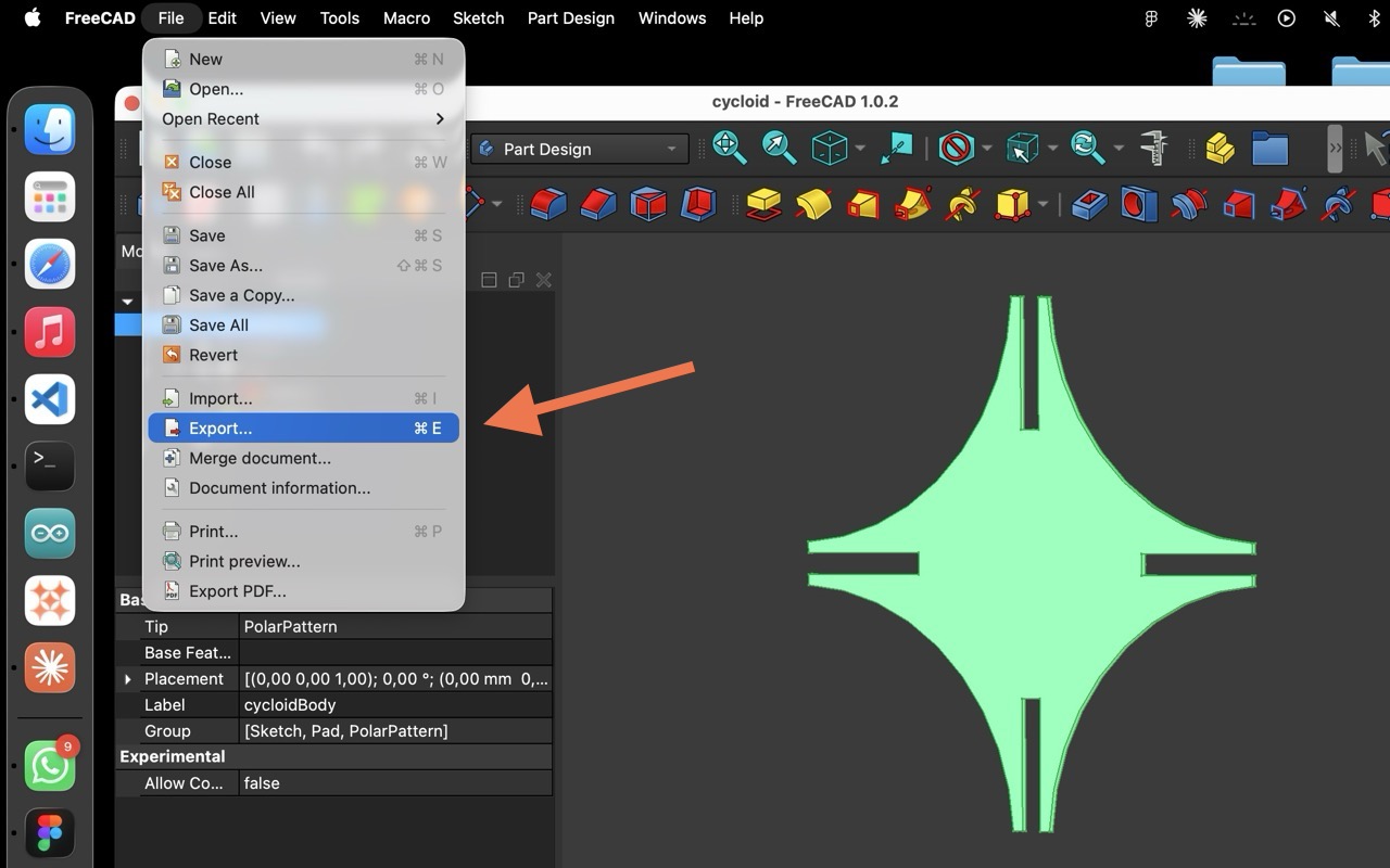
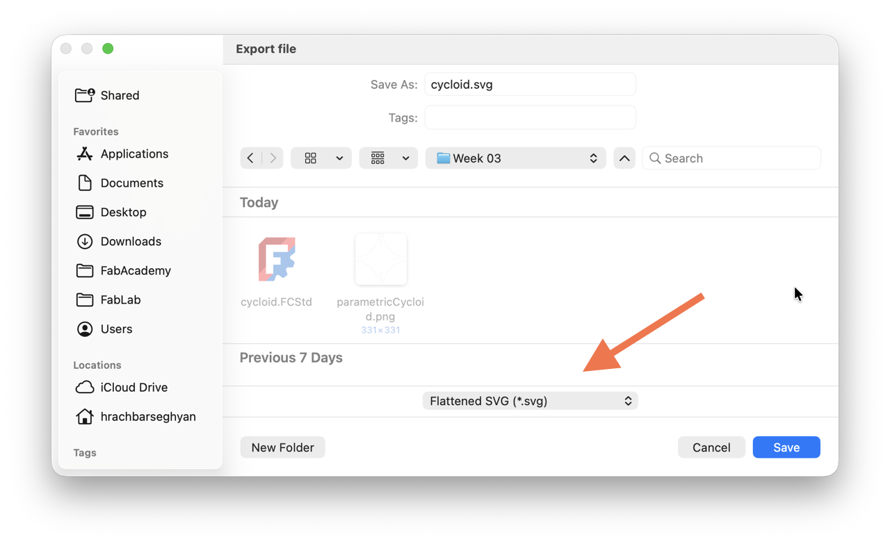
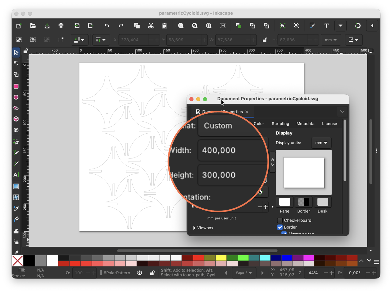
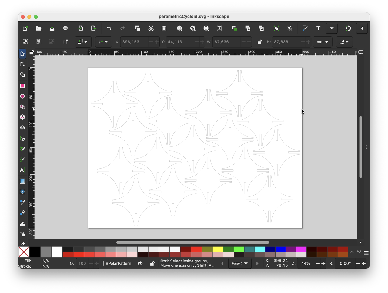
After this I exported the file into a flattened SVG and transported into Inkscape to make a nested set of the kit.
Testing
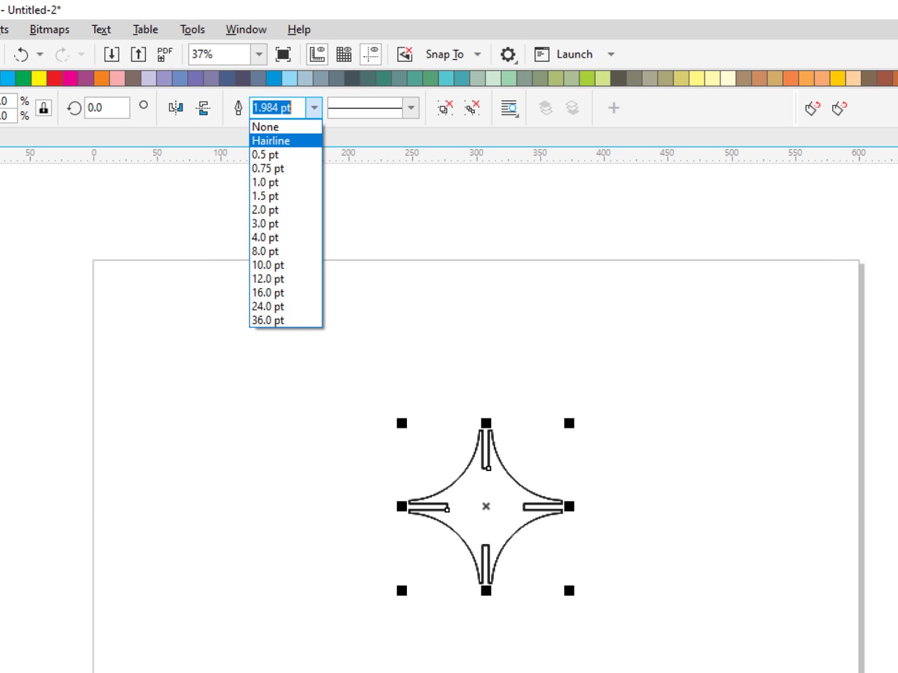
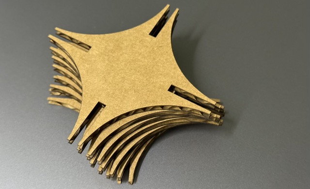
To test out how the shape would turn out with cardboard, whether the think npointy edges would deform from constructing, first I decided to make a set of four. In CorelDraw I changed the thickness of the contour to Hairline, duplicated, and transfered to RDWorks which is connected to the laser.
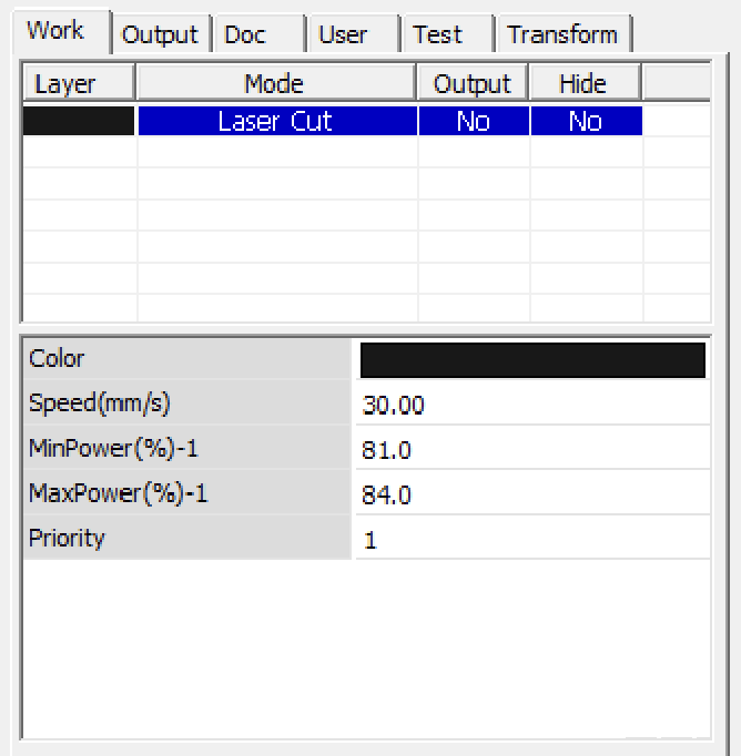 In RDWorks is where I changed the settings on the laser, that is the min/max speed, the power, the color settings switching between rastering and cutting. You can find this panel in the right side, under “Works” similar to the image on the right.
While this image does not correspond to the actual settings, I later changed the speed to 25mm/s, power 20-25%, and finally changed the output to yes while leaving as Laser Cut.
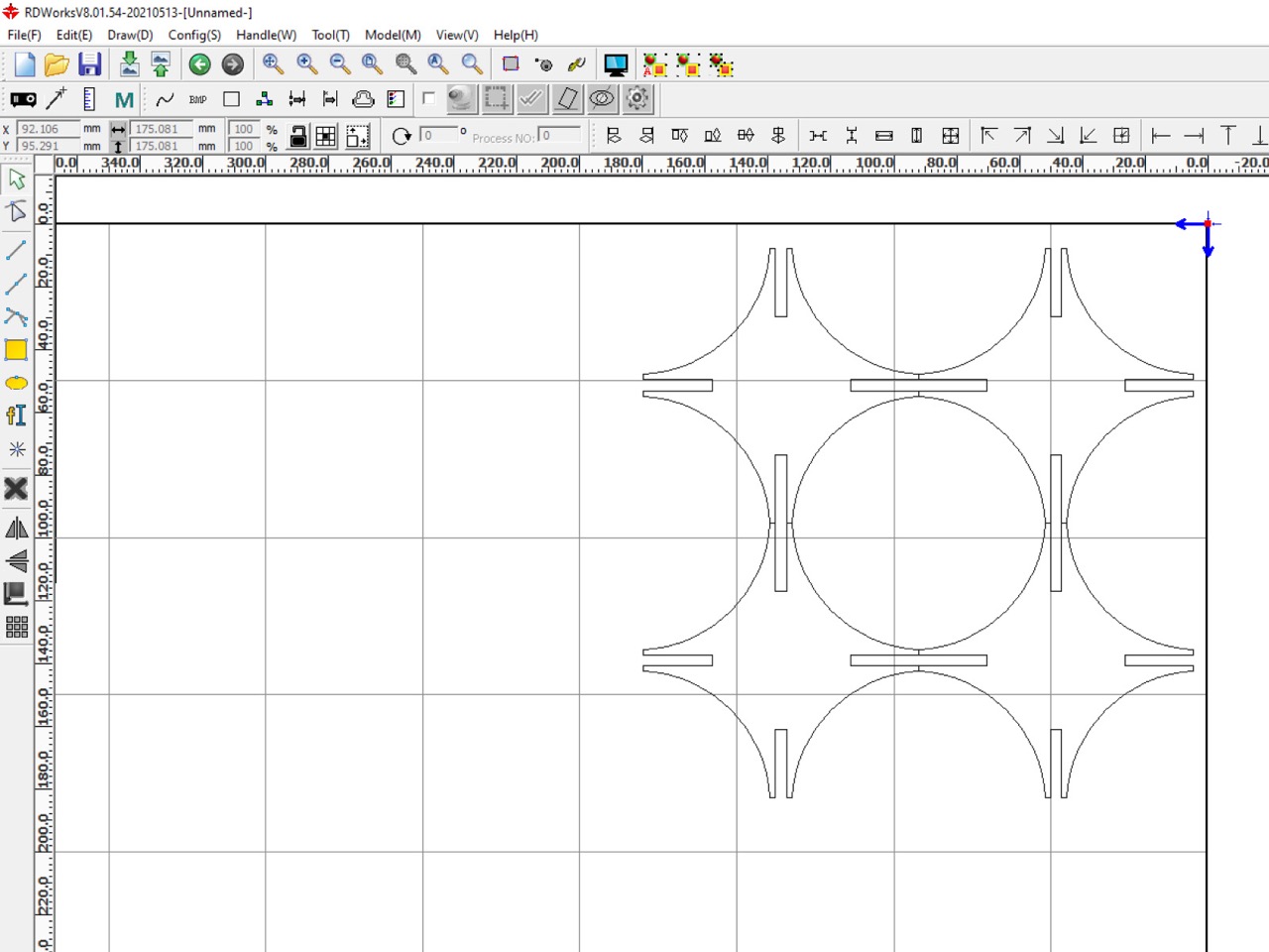
I had then taken the measurements of the cardboard sheets we had, and lay the pieces as neatly and tightly as possibly, while retaining from any intersections. I then sent this file to the laser cutter’s computer.
Assembling these was quite fun. But the larger it got, the more difficult it was to keep the edges intact. The thin and fragile ends would get deformed if inserted improperly, especially after 4-5 attempts the cardboard would get creased at its weakest points.

Vinyl Cutter, Part 1
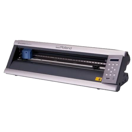
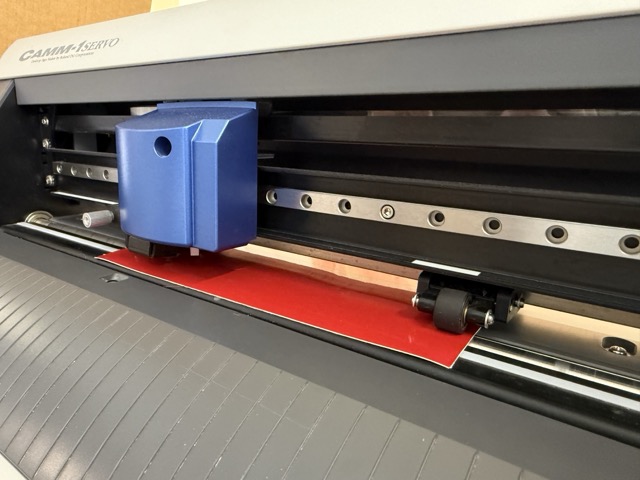
At our node we have a Roland Camm 1 Servo GX 24 vinyl cutter. The operations for the vinyl cutter were much simpler than the laser cutter. Only one thing was different – changing the blades. I additionally found this device’s tutorial on FabAcademy Tutorials’ page.
• loose securing of material
• wrong cutting force and speed
• dulled out/chipped blade tip
• edge thickness setting
 *Prompt3.2
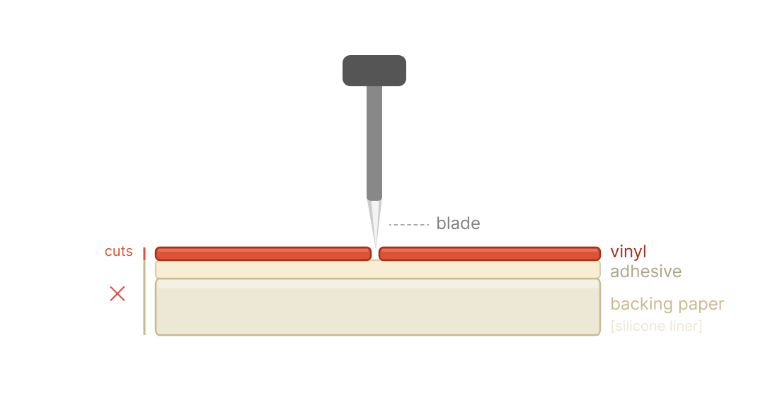
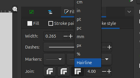 To avoid shredding your vinyl, you must set the stroke thickness to hairline so the blade treats the path as a single cut line [image on the right]. If the thickness is set to some millimeter not corresponding to ‘hairline’ thinkness, then software interprets it as a filled object, effectively destroying the material.
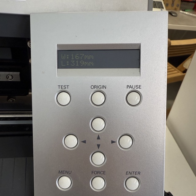
Another important metric is the applied force by the blade. If the pressure point is not high enough for the material, this could result in simply scratching the surface of the material [of course, if that is not what you are looking for]. So, in order to understand the compatible force in grams, at a given point under the blade, you can make test cuts with a dedicated button on the machine.
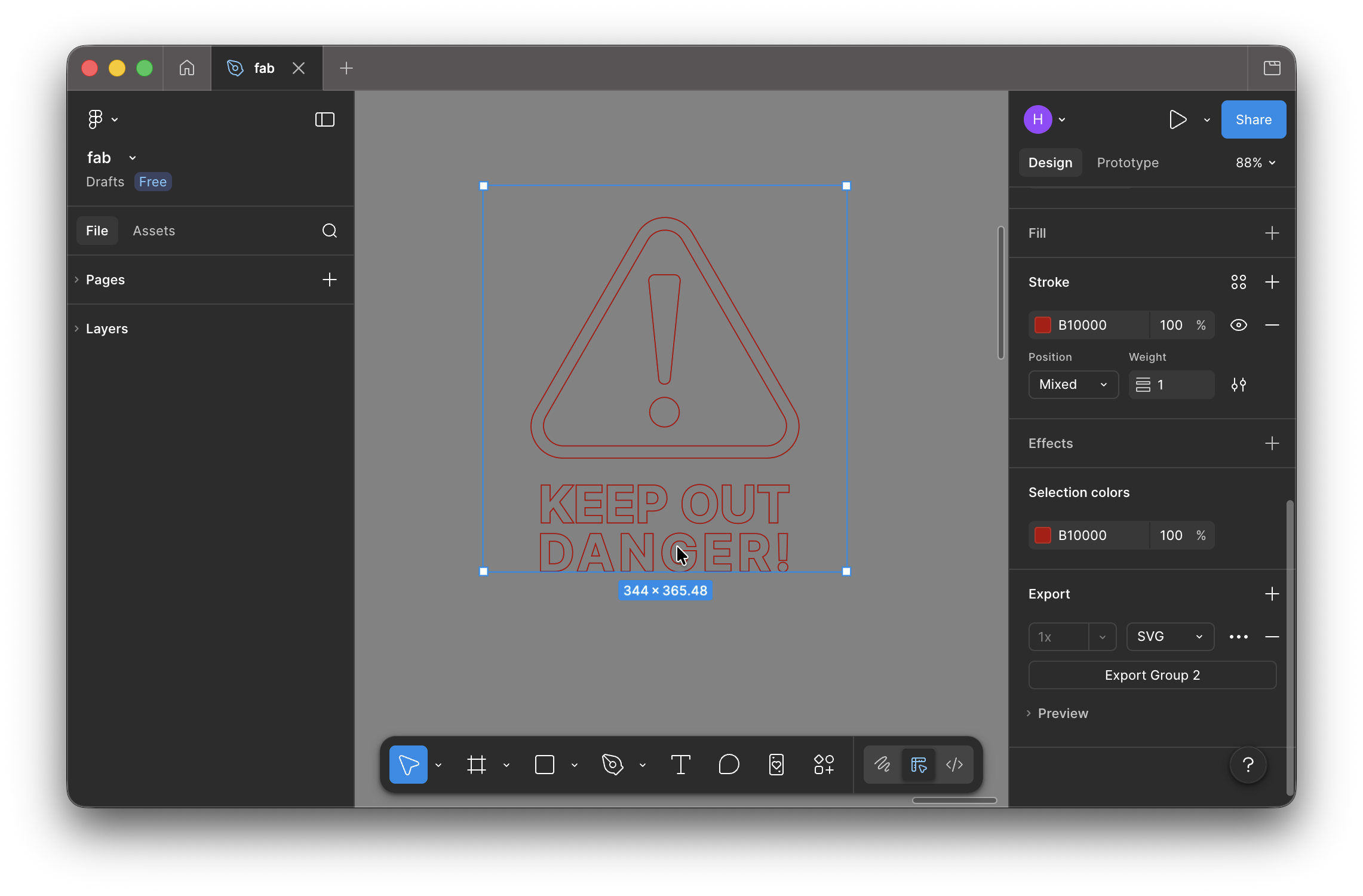
One of the example we completed as a group was a ‘danger’ sign. We first designed a simple example including both icons and finer details – text. Then sent the .svg file to the computer connected to the vinyl cutter. After, we picked a red shiny vinyl roll out, cut it into a small sheet and put it under the blade of the vinyl cutter.
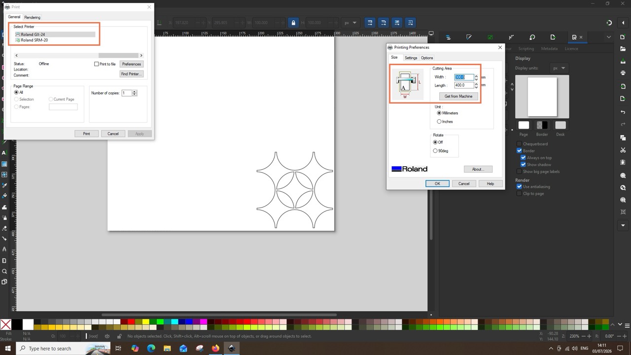
On the vinyl cutter we measured the size of the material to place the file over a corresponding size in the computer [left image below].
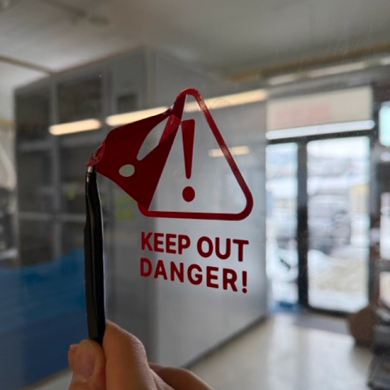
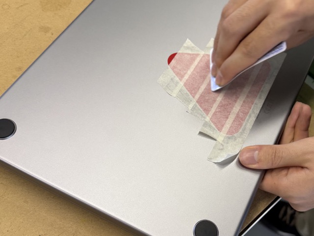
Once the process was done we first used masking tape to transfer the cutout without deforming it, and used a plastic card to attach it with maximal adhesion. We tried attching it onto a metallic surface, my computer, which it did not stick to. So after, we stuck it onto the CNC room’s door.
Vinyl Cutter, Part 2
I could not come up with something extrordinary to test the applications of the vinyl cutter, so I stuck to making a branded sticker.
I had taken a small piece of vinyl, and decided to cut the first test try on it. Again, I set the thickness of the outline as Hairline and sent it off to the printer by pressing Cmnd + P.
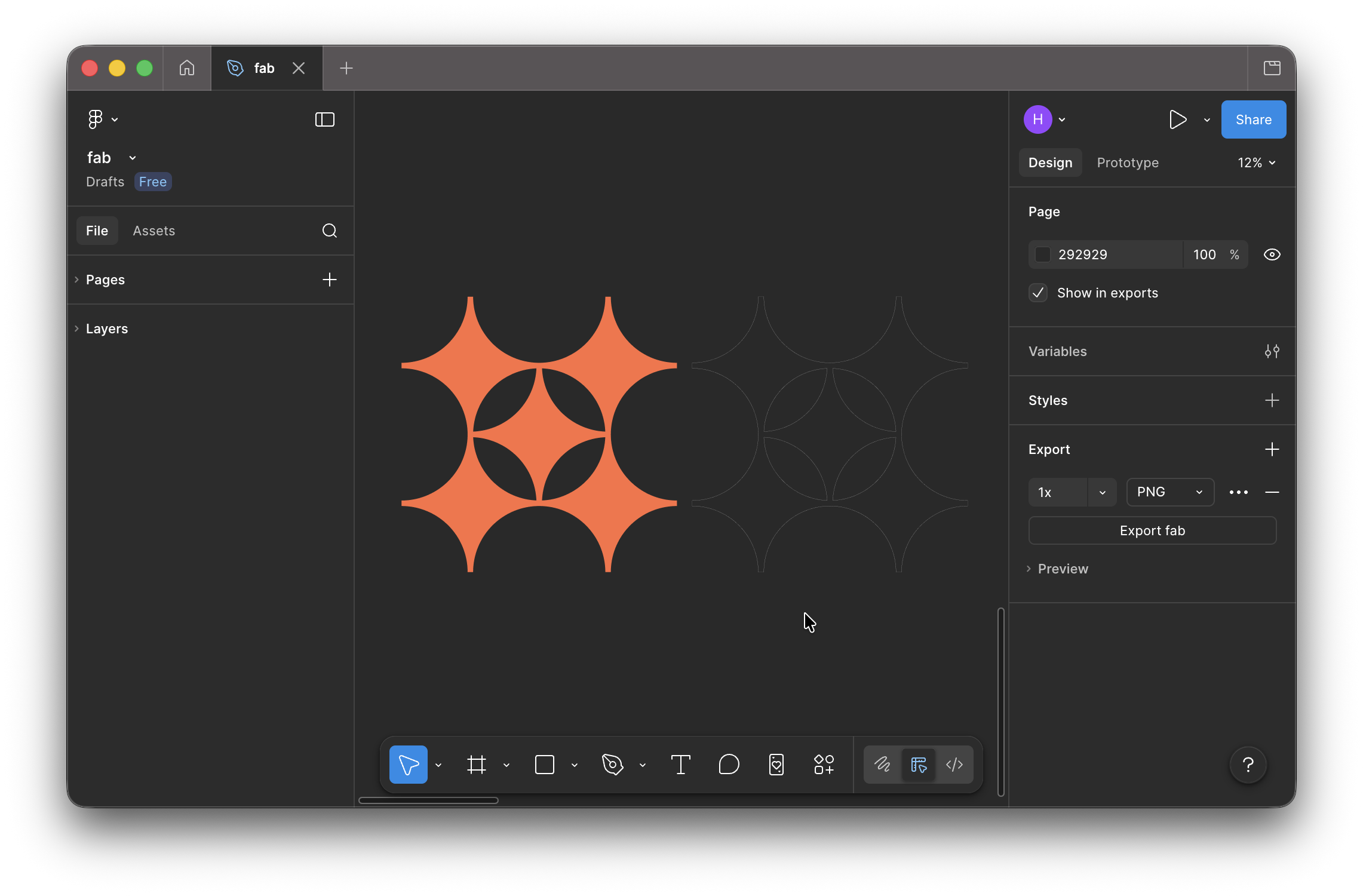
Yet again, I have continued with the series of projects based on my favicon. As I had previously created the .svg of it, I did not need to convert it from the 2D model made in FreeCAD. I simply removed the infill of the logo in Figma, and cut out the outline of it.
For the stickers, I did not specify a specific size. I only orientd by spacing several of these on a spare leftover roll, which was adjusted after having taken the meaurements of the piece, and changed the size in Inkscape.
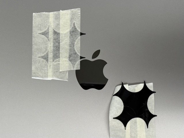
At first I was concerned that the thin tips would be damaged when transfering from the backing tape onto the computer. But again, I used masking tape and all went well.
Conclusion
I found quite fascinating working with a laser cutter, especially cutting cardboard. I am sure I will never forget the burnt smell of when opening the chamber door of the cutter.
With the vinyl cutter I am still struggeling to see its full use-potential. Though we have been told that it’s probably one of the most underrated tools in the labs, I believe in it, and still look for ways to harness its best use cases. But so far, for me it’s a complex sticker cutter [though I know that we can cut copper sheets on it too].
Resources
• Parametric Kit – SVG
• Parametric Kit – FreeCAD
Prompts
Prompt3.1 It’s known that a kerf in laser cutting is the width of the material that is vaporized or burned away by the laser beam as it makes a cut. I need visuals for it, please make it as simple as you can. So simple so that a 5 year old would understand.
Prompt3.2 Can you create an illustration for a vinyl cutter? Simply its layers, how the vinyl has a backing paper, and how the blade runs over it.