Week 10: Output Devices
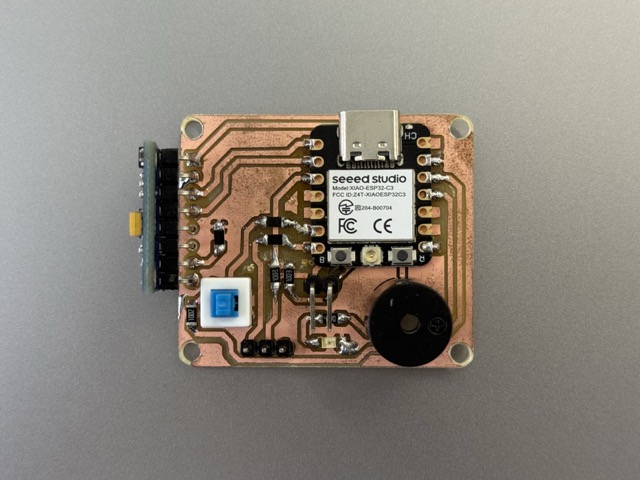
*Updated PCB with Gyroscope.
Group Assignment
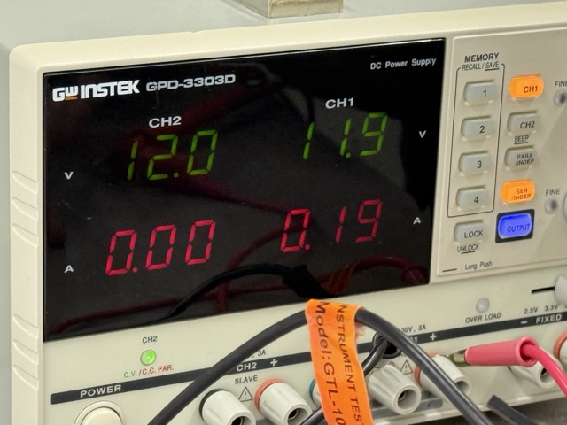
For this week’s group assignment we had taken a power supply, and a multimeter. We learned how to configure the multimeter to measure current by switching the red probe to the mA/µA mode and wiring the device in series to act as a bridge. The testing process proved critical for real-world hardware design, especially since ignoring current consumption previously caused a PCB to burn. By reinforcing how theory directly impacts hardware safety, these tests highlighted why calculating and measuring component draw is essential before finalizing any design.
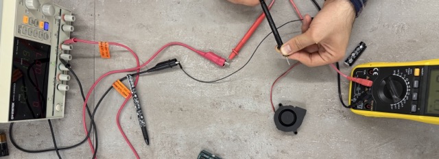
Wiring these two together helped us understand the difference and the accurance between these two measuring devices. The chaining method was done to increase the accuracy of the measurements, as the power supply’s indications are not as precise.
On the multimeter there are 4 ports, for a pair of an anode and a cathode. Depending an the need we take out the cathode [the red one] and plug it into other ports. The anode [the black one] remains unchanged, and is not plugged out.
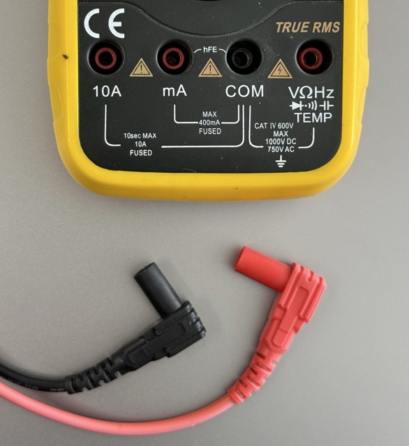
The Ground [Black Probe]:
COM: The "Common" port. The black lead always goes here
The Multi-Tool [Red Probe]:
V Ω Hz Temp Diode: this is your "everything else" port – use this for measuring voltage, resistance, frequency, temperature, and testing diodes
The Current Measures [Red Probe]:
10A: Only for measuring high current [up to 10 Amps]
mA: Only for measuring low current [milliamps]
The Motor
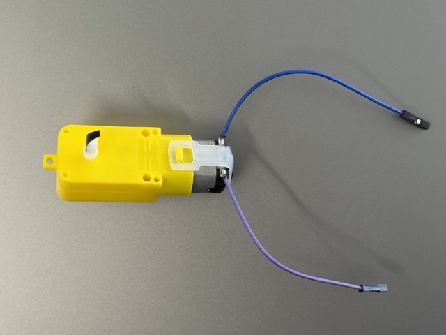 We took a simple DC motor, and connected its two pins to the wire from of power supply and multimeter. As this is a direct current [DC] motor, it does not have designated anode or cathode, meaning it will work no matter the order of connections to the pins.
The Fan
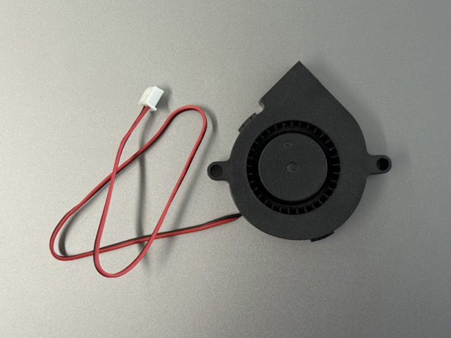 We had done the same experiment with a simple blower fan.
The LCD
We also ended up testing one of my older prjoects from Week 4. The project was a Morse Code decoder, which used and LCD to output the results.
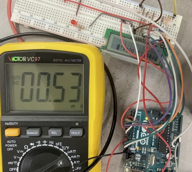
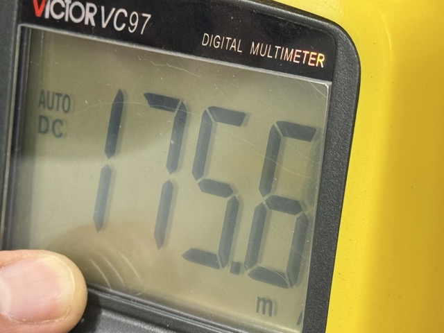
Through testing with a DC power supply, we measured the exact current consumption of three components. We found that the DC motor draws around 180 mA under a 9V load, the fan consumes roughly 74.6 mA, and the LCD has a much lower draw of just 0.53 mA. Gathering these values gave us the data needed to safely power the components.
Individual Assignment
Output device testing continued using the XIAO RP2040, focusing specifically on a servo motor and a buzzer. These components were validated using the improved PCB layout designed in Week 9.
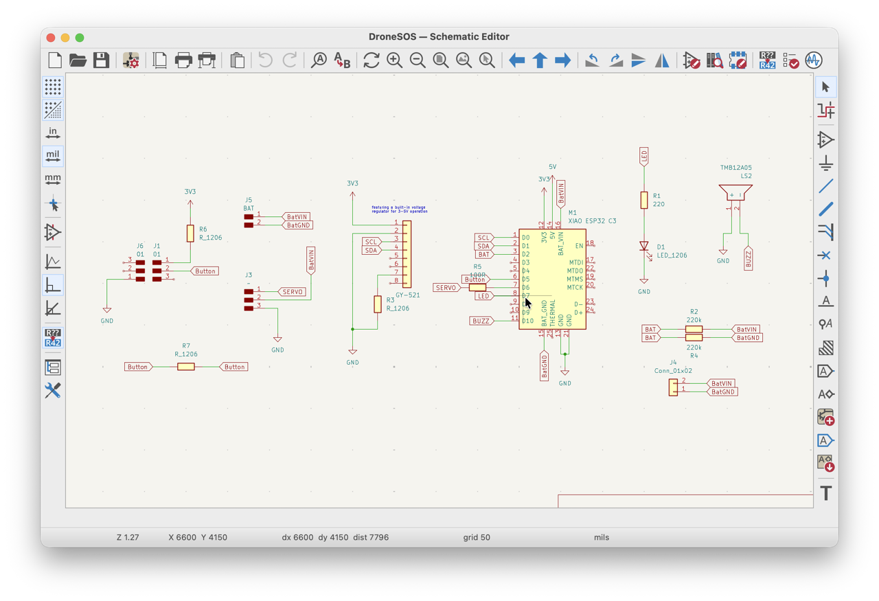
*Schematics reference.
Servo Motor
 The second most important component for my final project is door actuation. I had been thinking of ways to solve this matter, but a servo motor seemed to be the easiest and most staightforward option for an initial prototype. So I started looking into servo options.
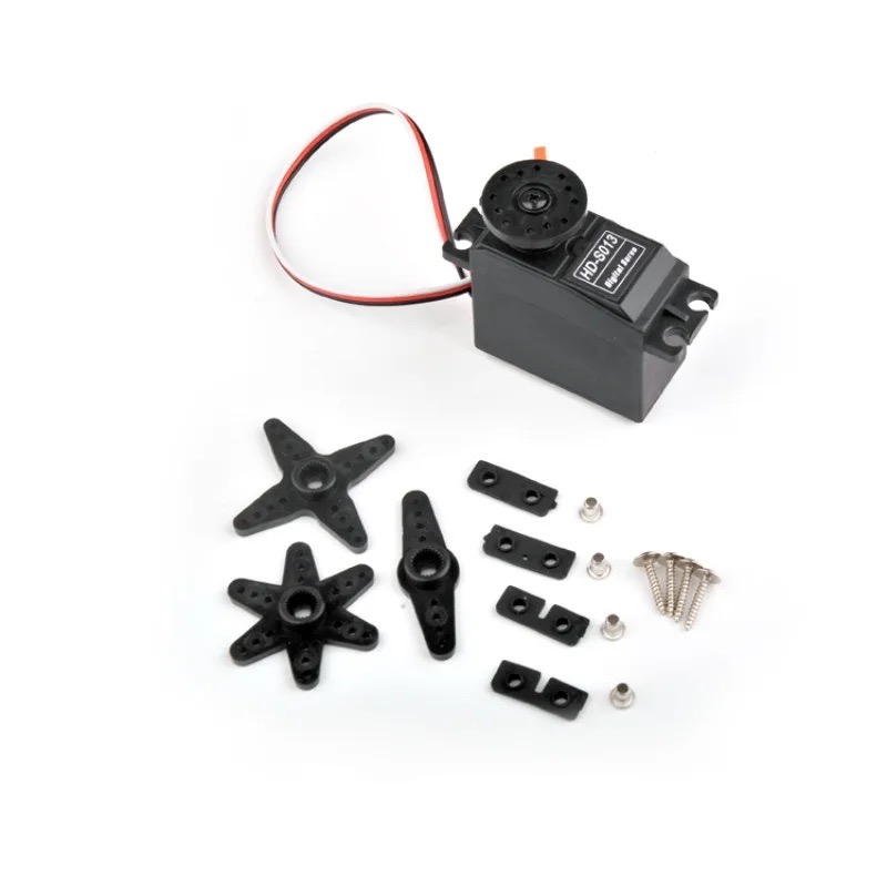
At the lab I found several small format 5V servos – very small, heavy metalic cased, light metalic geared, and all plastic servos too. For reliable actuation, and peace of mind I was recommended by Rudolf [one of my local instructors] to use a metalic geared servo.
Test Rig
After having chosen the servo type, I proceeded to rigging the test with the servo. I designe a cutout of what the case would potentially look like. Then screwed it onto a plywood piece, and tied it to the lever using a string. I held the servo in place, whereas screwing it in would not let the lever move freely.
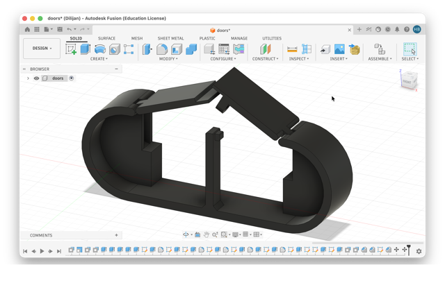
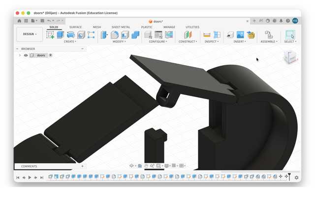
The setup worked fine, and my doubt on using a servo had gone away. I was sure that the servo could release the doors from their closed position [video below].
The Code
C++

#include <ESP32Servo.h>

Servo myServo;  // Create servo object
const int servoPin = D6;

void setup() {
  Serial.begin(115200);
  myServo.setPeriodHertz(50); // Standard 50Hz servo
  myServo.attach(servoPin, 500, 2400); // Attach to pin D6, pulse widths (μs)

  myServo.write(90); // Initialize at 90 degrees
}

void loop() {
  // Listen for commands from the Serial Monitor
  if (Serial.available() > 0) {
    String command = Serial.readStringUntil('\n');
    command.trim(); // Remove any stray whitespace or newlines

    if (command.equalsIgnoreCase("Open")) {
      Serial.println("Moving to 135 degrees...");
      myServo.write(135);

      delay(1000); // Wait 1 second

      Serial.println("Returning to 90 degrees.");
      myServo.write(90);
    }
  }
}
*Prompt10.1
Buzzer
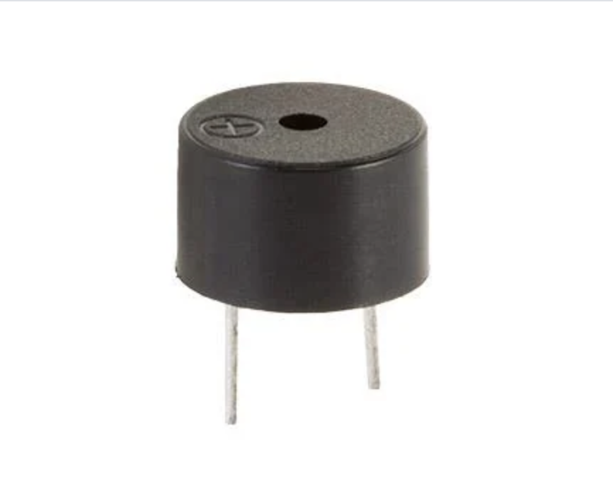 The device also incorporates a buzzer, designed to assist the pilot in locating a crashed drone via sound tracking. To achieve this, the design utilizes a passive 5V buzzer.
How does it work?
The working principle of the passive buzzer module is based on the piezoelectric effect. When an electrical signal is applied to the buzzer, it causes a piezoelectric crystal inside the buzzer to vibrate at a specific frequency. This vibration produces sound waves that we can hear.
The Code
C++

const int buzzerPin = D2; // Pin D2 connects to the buzzer

void setup() {
  pinMode(buzzerPin, OUTPUT);
}

void loop() {
  // High "Deee" sound (Normal buzzer resonant frequency)
  tone(buzzerPin, 2300);
  delay(300);

  // Lower "Dooo" sound (Siren drop pitch)
  tone(buzzerPin, 1800);
  delay(300);
}
*Prompt10.2
Conclusion
Did I face any problems? – No, this week everything was fine.
It’s always interesting to discover something new. From a first glance it seems that these measuring devices are all the same, and almost look the same, but just different models. Changing these paradigms are always evoking that you cannot possibly know everything, even if you are a polymath.
Just about two weeks ago I had a brief thought cross my mind on how could one measure the power consumption, and estimate requirements for their devices. While I did not give much though to it, and did not even search online, but here I was, doing week 10 and getting answers to my questions.
References
• Test Rig
Prompt
Prompt10.1 Write a program for a XIAO ESP32 C3 to control a 5V servo motor connected to pin D6. The system is designed to initialize the servo at 90 degrees and listen for the command “Open” via the Serial Monitor. Once that exact text is received, the servo immediately rotates to 135 degrees, holds that position for exactly one second, and automatically returns to its original 90 degree resting position.
Prompt10.2 To create a “deee-dooo” siren sound on an XIAO RP2040 using pin D2, the code alternates between a high tone of 2300 Hz and a lower tone of 1800 Hz to match a standard buzzer’s optimal resonant frequency.