11. Networking and communications
For this week’s group assignment, we had to send a message between two projects.
Dilijan Lab
This week, Mariam and Hrach had to establish communication between two ESP32-C3 boards so that one board could send a message while the other received it.
They used the MQTT publish/subscribe method through an MQTT broker.
Their main goal was to connect Mariam’s Final Project joystick with Hrach’s Final Project Drone SOS Case. The idea was that when the button on the joystick is pressed, the Drone SOS Case automatically opens.
🔌 Experiment 1 — Basic MQTT Communication
Before moving on to that, they first connected the two ESP32-C3 MCUs to fully understand how MQTT works.
This is the code for the first ESP32-C3, which acts as the publisher and sends a message to the second ESP32-C3 through the Serial Monitor:
#include <WiFi.h>
#include <PubSubClient.h>

const char* ssid     = "staff";
const char* password = "SRGB2020";
const char* broker   = "broker.hivemq.com";
const char* topic    = "chat/xiao";
const char* DEVICE_ID = "device_A";  // change to "device_B" on the other one

WiFiClient wifiClient;
PubSubClient client(wifiClient);

void callback(char* topic, byte* payload, unsigned int length) {
  String msg = "";
  for (int i = 0; i < length; i++) msg += (char)payload[i];
  Serial.println(">> " + msg);
}

void reconnect() {
  while (!client.connected()) {
    Serial.print("Connecting MQTT...");
    if (client.connect(DEVICE_ID)) {
      Serial.println("New message from #1");
      client.subscribe(topic);
    } else {
      delay(2000);
    }
  }
}
AI prompt:
I have two ESP32-C3 boards connected through MQTT using broker.hivemq.com.
And this is the code for the second ESP32-C3, which connects to the first MCU and receives the message:
#include <WiFi.h>
#include <PubSubClient.h>

WiFiClient wifiClient;
PubSubClient mqtt(wifiClient);

void callback(char* topic, byte* payload, unsigned int length) {

  Serial.print("Received: ");

  for (int i = 0; i < length; i++) {
    Serial.print((char)payload[i]);
  }

  Serial.println();
}

void setup() {

  Serial.begin(115200);

  WiFi.begin("staff", "SRGB2020");

  while (WiFi.status() != WL_CONNECTED);

  mqtt.setServer("broker.hivemq.com", 1883);
  mqtt.setCallback(callback);

  while (!mqtt.connected()) {
    mqtt.connect("ESP32_2");
  }

  mqtt.subscribe("fablab/test");
}

void loop() {
  mqtt.loop();
}
AI prompt:
I have two ESP32-C3 boards connected through MQTT using broker.hivemq.com.
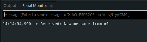
Serial Monitor showing the received message
🕹️ Experiment 2 — Button Triggered Message
Hrach’s and Mariam’s second experiment was again to send a message, but this time the message would be sent when the button on the joystick was pressed.
Here is the joystick code:
#include <WiFi.h>
#include <PubSubClient.h>

#define PIN_SW 5

const char* ssid = "staff";
const char* password = "SRGB2020";

const char* mqtt_server = "broker.hivemq.com";

WiFiClient espClient;
PubSubClient client(espClient);

void reconnect() {
  while (!client.connected()) {

    String clientId = "JoystickESP32-";
    clientId += String((uint32_t)ESP.getEfuseMac(), HEX);

    if (client.connect(clientId.c_str())) {
      Serial.println("MQTT Connected");
    } else {
      Serial.print("MQTT Failed, rc=");
      Serial.println(client.state());
      delay(2000);
    }
  }
}

void setup() {
  Serial.begin(115200);

  pinMode(PIN_SW, INPUT_PULLUP);

  WiFi.begin(ssid, password);

  Serial.print("Connecting WiFi");

  while (WiFi.status() != WL_CONNECTED) {
    delay(500);
    Serial.print(".");
  }

  Serial.println("\nWiFi Connected");

  client.setServer(mqtt_server, 1883);
}

void loop() {

  if (!client.connected())
    reconnect();

  client.loop();

  static bool lastState = HIGH;

  bool currentState = digitalRead(PIN_SW);

  if (lastState == HIGH && currentState == LOW) {

    client.publish("fablabarmenia/robot/button", "PRESSED");

    Serial.println("Published: PRESSED");

    delay(300);
  }

  lastState = currentState;
}
AI prompt:
When I press the joystick button (SW), ESP32-C3 #2 publishes an MQTT message.
The code for the second ESP32-C3 is the same as the one shown above.
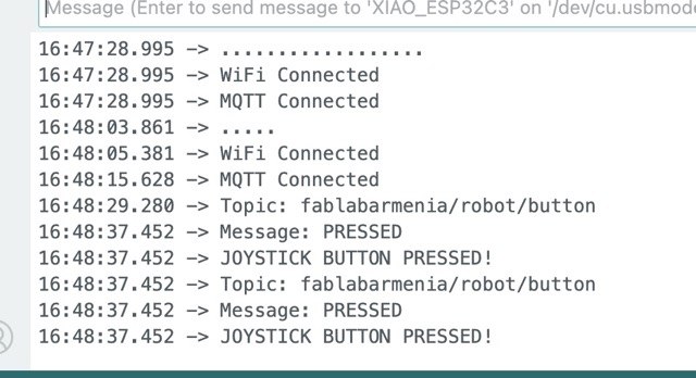
Serial Monitor showing the received message
🚁 Final Goal — Opening the Drone Parachute Case
Finally, Mariam and Hrach achieved their goal of opening Hrach’s drone parachute case using the button on the joystick.
The joystick code does not change because it simply sends a message to the second chip again when the button is pressed.
And the following code was uploaded to the Drone Parachute Case chip:
#include <WiFi.h>
#include <PubSubClient.h>
#include <ESP32Servo.h>

const char* ssid = "YOUR_WIFI";
const char* password = "YOUR_PASSWORD";

const char* mqtt_server = "broker.hivemq.com";

const int SERVO_PIN = D6;   // GPIO21

Servo deployServo;

bool triggered = false;   // latch: deploy once, don't re-trigger mid-flight


WiFiClient espClient;
PubSubClient client(espClient);

void callback(char* topic, byte* payload, unsigned int length) {

  String message = "";

  for (int i = 0; i < length; i++) {
    message += (char)payload[i];
  }

  Serial.print("Topic: ");
  Serial.println(topic);

  Serial.print("Message: ");
  Serial.println(message);

  if (message == "PRESSED") {
    Serial.println("JOYSTICK BUTTON PRESSED!");
    deployServo.write(180);
    delay(500);
    deployServo.write(90);
  }
}

void reconnect() {

  while (!client.connected()) {

    String clientId = "HrachESP32-";
    clientId += String((uint32_t)ESP.getEfuseMac(), HEX);

    if (client.connect(clientId.c_str())) {

      Serial.println("MQTT Connected");

      client.subscribe("fablabarmenia/robot/button");

    } else {

      Serial.print("MQTT Failed, rc=");
      Serial.println(client.state());

      delay(2000);
    }
  }
}

void setup() {

  Serial.begin(115200);

  WiFi.begin("staff", "SRGB2020");

  deployServo.attach(SERVO_PIN);
  deployServo.write(90);  // start position

  while (WiFi.status() != WL_CONNECTED) {
    delay(500);
    Serial.print(".");
  }

  Serial.println("\nWiFi Connected");

  client.setServer(mqtt_server, 1883);
  client.setCallback(callback);
}

void loop() {

  if (!client.connected())
    reconnect();

  client.loop();
}
AI prompt:
When I press the joystick button (SW), ESP32-C3 #2 publishes an MQTT message.
Here is the result in video format.
Gyumri lab
For this group assignment, Gevorg and Ani sent a message between two of their projects using the I2C protocol. Gevorg’s board, which carries an MQ-7 gas sensor and a piezo buzzer, acted as the Main. Ani’s board, which drives an LED strip through a MOSFET, acted as the Secondary, addressed at a fixed I2C address.
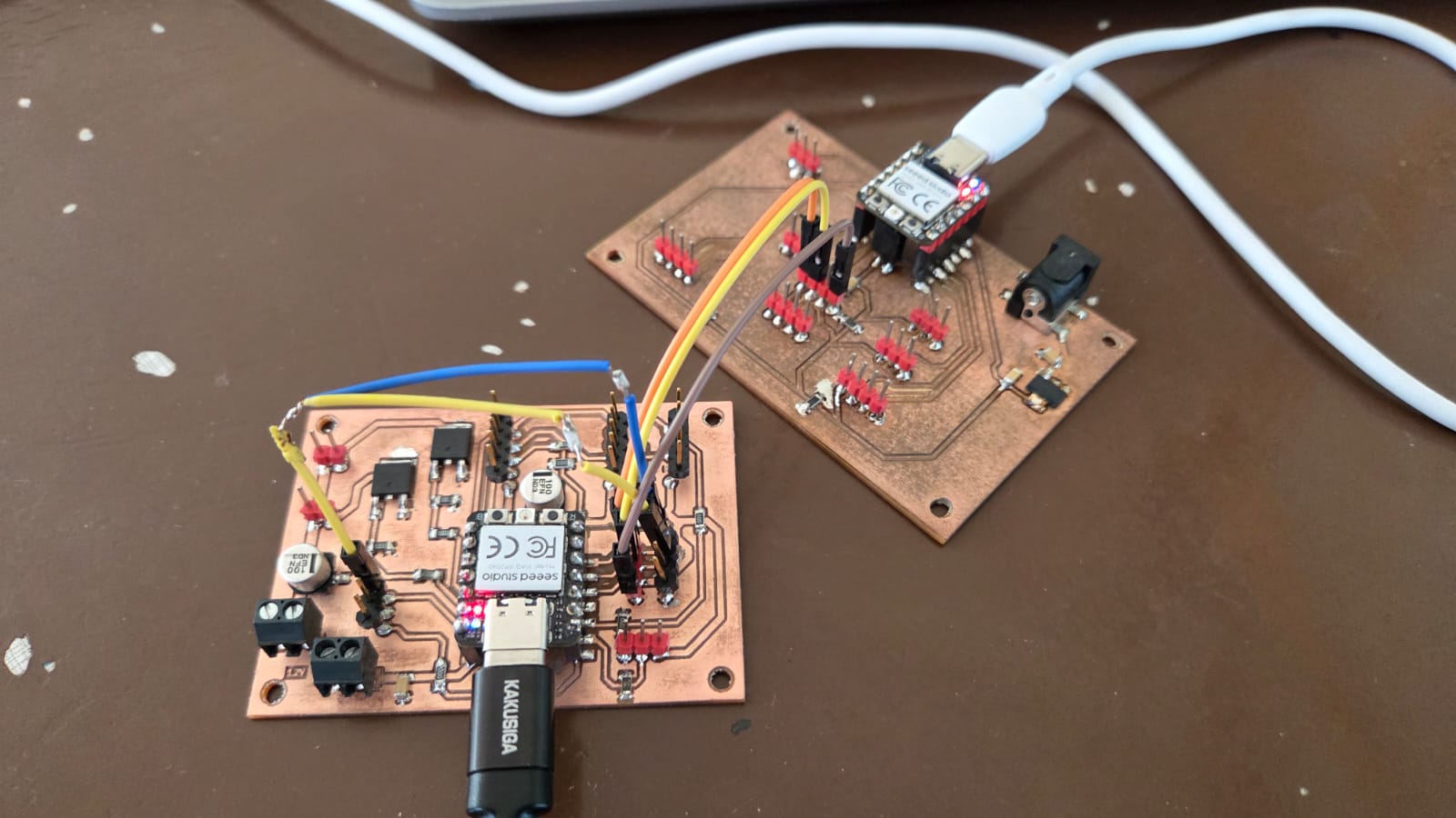
The goal was for Gevorg’s board to read the MQ-7 sensor and decide, based on a threshold, whether the air should be considered safe or dangerous, then send this as a single byte to Ani’s board. Ani’s board, listening at its fixed address, would receive this byte and switch the LED strip from steady to a fast blink whenever the value indicated danger.
Programming was done in the Arduino IDE for the Seeed XIAO RP2040. On this board, SDA and SCL are physically broken out on pins D4 and D5, but the I2C pins aren’t fixed in the arduino-pico core the way they are on classic Arduino boards, so they need to be set explicitly in code with Wire.setSDA() / Wire.setSCL() before Wire.begin(). The bus also needs pull-up resistors — we added 4.7 kΩ from SDA to 3.3V and 4.7 kΩ from SCL to 3.3V, once for the whole bus.
Before writing the actual sensor/LED logic, we first checked that the two boards could talk to each other at all, by sending a single test byte back and forth and printing the result to Serial.
Main board, test version:
#include <Wire.h>

#define SECONDARY_ADDR 0x10

void setup() {
  Wire.setSDA(6);  // D4
  Wire.setSCL(7);  // D5
  Wire.begin();    // join the I2C bus as Main
  Serial.begin(115200);
}

void loop() {
  Wire.beginTransmission(SECONDARY_ADDR);
  Wire.write(0x01);
  byte result = Wire.endTransmission();

  if (result == 0) {
    Serial.println("Sent OK");
  } else {
    Serial.print("Send failed, error: ");
    Serial.println(result);
  }

  delay(500);
}
Secondary board, test version:
#include <Wire.h>

#define SECONDARY_ADDR 0x10

void receiveEvent(int howMany) {
  while (Wire.available()) {
    byte cmd = Wire.read();
    Serial.print("Received: ");
    Serial.println(cmd);
  }
}

void setup() {
  Wire.setSDA(6);  // D4
  Wire.setSCL(7);  // D5
  Wire.begin(SECONDARY_ADDR);   // join the I2C bus at a fixed address
  Wire.onReceive(receiveEvent);
  Serial.begin(115200);
}

void loop() {
}
With this running, the Main board printed Sent OK once a second, and the Secondary board printed Received: 1 in response — confirming the bus, the addressing, and the pull-ups were all working before adding the actual sensor and the LED strip.
(PHOTO — Serial Monitor on both boards during the basic connection test)
Once that worked, we moved on to the actual sensor and LED strip. Let’s write the code.
Main board (Gevorg’s board):
#include <Wire.h>

#define MQ7_PIN A0
#define SECONDARY_ADDR 0x10
#define THRESHOLD 600

void setup() {
  Wire.setSDA(6);  // D4
  Wire.setSCL(7);  // D5
  Wire.begin();    // join the I2C bus as Main
  Serial.begin(115200);
}

void loop() {
  int gasValue = analogRead(MQ7_PIN);
  Serial.println(gasValue);

  Wire.beginTransmission(SECONDARY_ADDR); // transmit to device #0x10
  Wire.write(gasValue > THRESHOLD ? 0x01 : 0x00);
  Wire.endTransmission();

  delay(200);
}
Let’s explain the code step by step:
- Set SDA and SCL to D4/D5 explicitly, join the I2C bus as Main, and start Serial for debugging.
- In an endless loop, read the MQ-7 sensor on pin A0.
- Compare the reading against a fixed threshold to decide whether the air is safe or dangerous.
- Send the result as a single byte (
0x00or0x01) to the Secondary board’s address. - The cycle repeats with a 200 ms delay.
Secondary board (Ani’s board):
#include <Wire.h>

#define SECONDARY_ADDR 0x10
#define MOSFET_PIN D9

volatile bool alertState = false;

void receiveEvent(int howMany) {
  while (Wire.available()) {
    byte cmd = Wire.read();
    alertState = (cmd == 0x01);
  }
}

void setup() {
  pinMode(MOSFET_PIN, OUTPUT);
  Wire.setSDA(6);  // D4
  Wire.setSCL(7);  // D5
  Wire.begin(SECONDARY_ADDR);   // join the I2C bus with address 0x10
  Wire.onReceive(receiveEvent); // register event
}

void loop() {
  if (alertState) {
    digitalWrite(MOSFET_PIN, HIGH);
    delay(100);
    digitalWrite(MOSFET_PIN, LOW);
    delay(100);
  } else {
    digitalWrite(MOSFET_PIN, LOW);
  }
}
Let’s explain the code step by step:
- Set SDA and SCL to D4/D5, join the I2C bus at the fixed address
0x10, and register the receive handler. - Whenever a byte arrives from the Main board, store whether it equals
0x01(alert) or not. - In the main loop, if the alert flag is set, blink the MOSFET pin on and off quickly; otherwise keep it low.
Let’s look at the result of the work: