Machine Building Group 3
Presentation Machine 3
The Idea
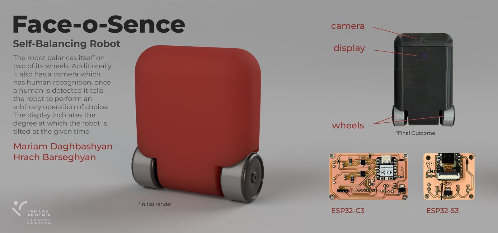
Two weeks before the machine building week, we had thought about making a robot vacuum cleaner. Then when the week had arrived, we changed our initial idea and spent a day ideating. After many ideas, and a lot of back and forth, eventually, we landed on the idea of a two-wheeled self balancing robot. Whereas the inspiration came from both bionic robots and agentic AI.
The Philosophy
We and our instructors know that before conquering bionic robots and agentic AI, we first need to solve mobility tasks. In other words, if the end goal is building robots that move and think on their own, then movement has to come first. Rather than starting with something straightforward, we figured we would pick a problem that’s already a bit harder than it required to be. A self-balancing robot has to earn its stability constantly, it’s not just rolling from one point to point another, it’s working continuously to stay upright –– in some sence a 2-in-1 task. It felt true to the bigger picture we had in mind, but the grand idea behind was learning by failing.
Project Ditribution
The work was divided between the two of us – Mariam, and Hrach.
Aditionally, we were continuously supervised by Onik, one of our local instructors.
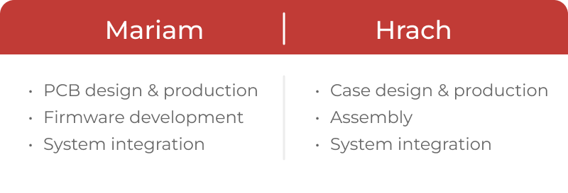
👥 Mariam’s Individual Contribution — Self-Balancing Robot
Full page: Mariam’s Week 12 documentation
🤖 Main Robot
This week the group assignment required us to design a machine that includes mechanism + actuation + automation + function + user interface, build the mechanical parts and operate it manually, and document both the group project and individual contributions.
After discussing many ideas, we decided to build a self-balancing robot. Mariam also proposed adding a camera that detects a smile — and when a smile is detected, the robot deliberately loses balance 😄. This made the individual task significantly more complex, but led to exploring several interesting technologies.
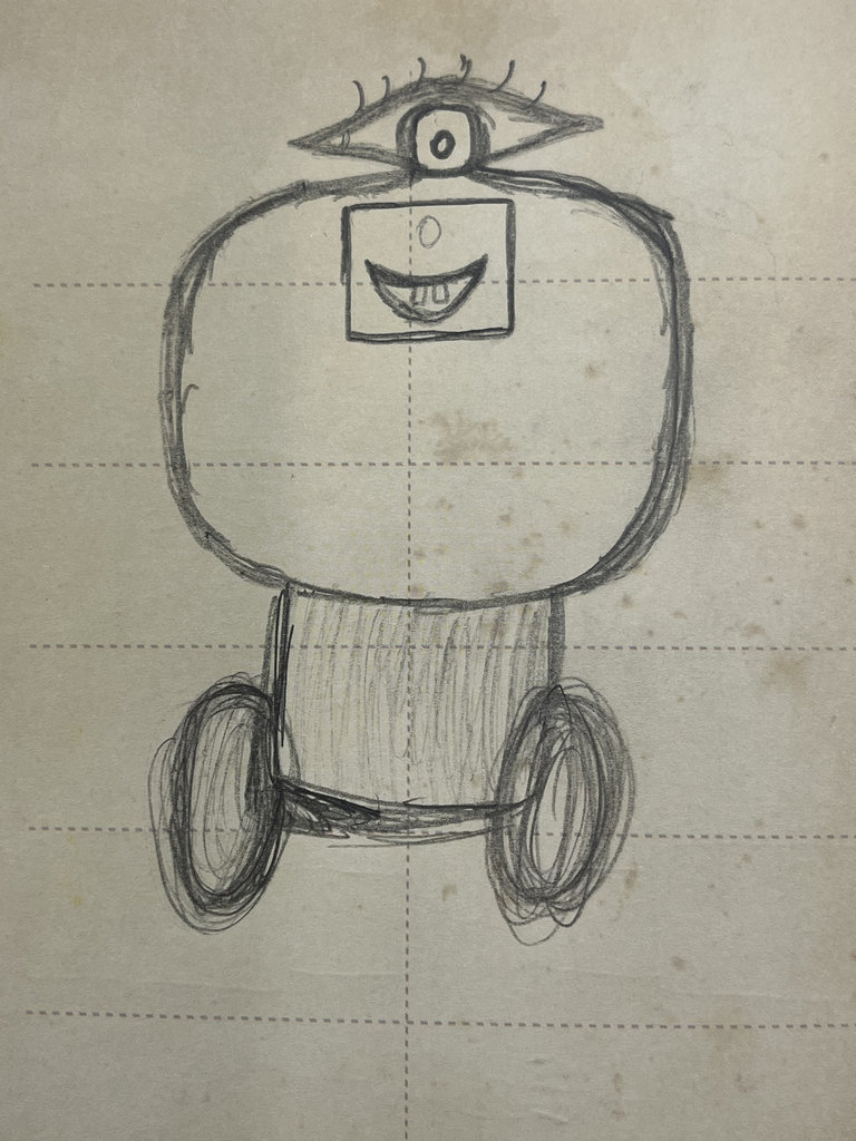
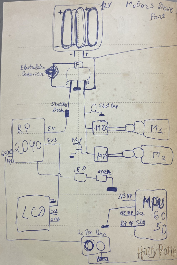
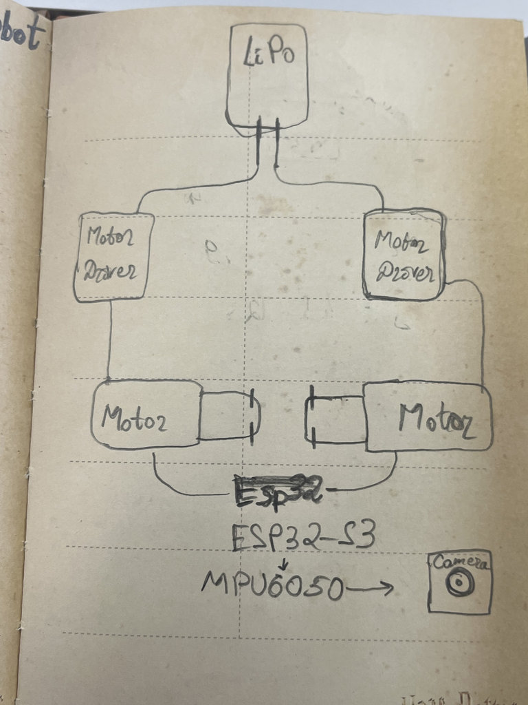
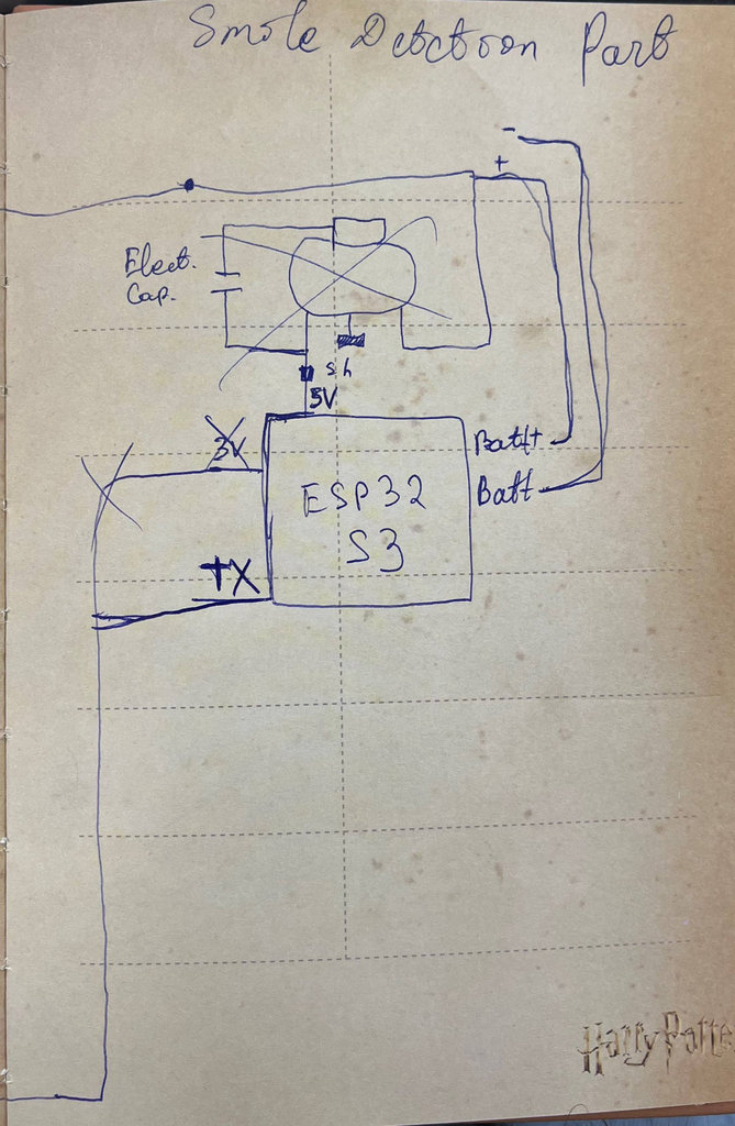
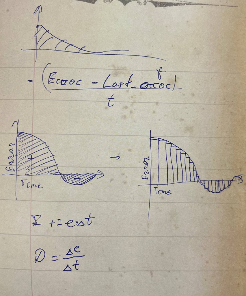
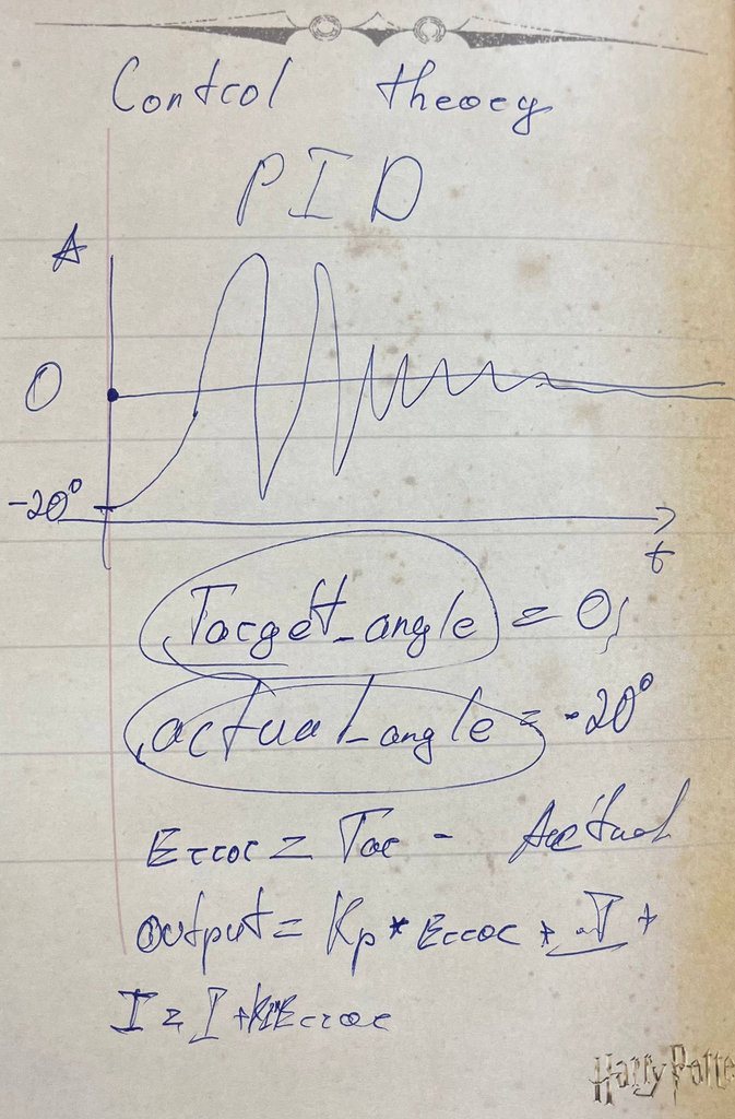
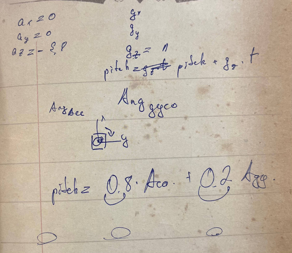
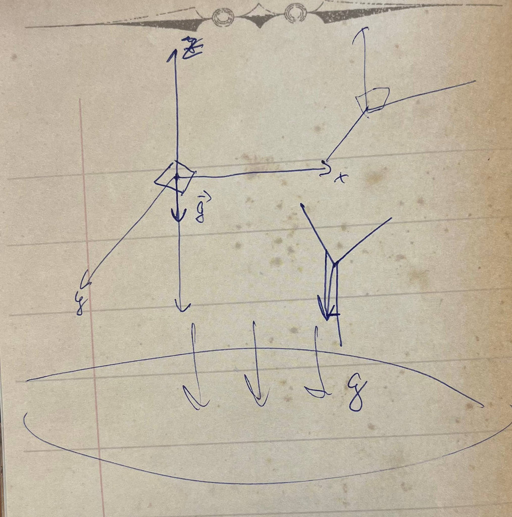
📐 Sketches of Electronics Part and Control Logic
Here are some example sketches created during research — this approach helps build stronger understanding, functioning as a visual database from first idea to final result.
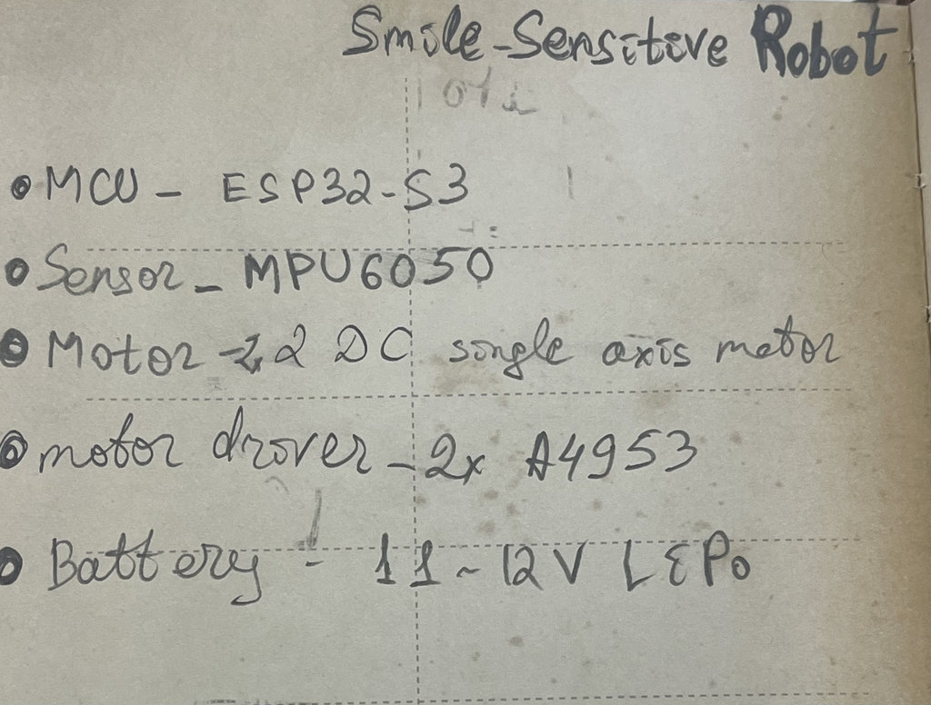
🔌 Main Robot — Electronics
After finishing the research, work began on the part of the robot responsible for maintaining balance. The following components are needed for the main functionality:
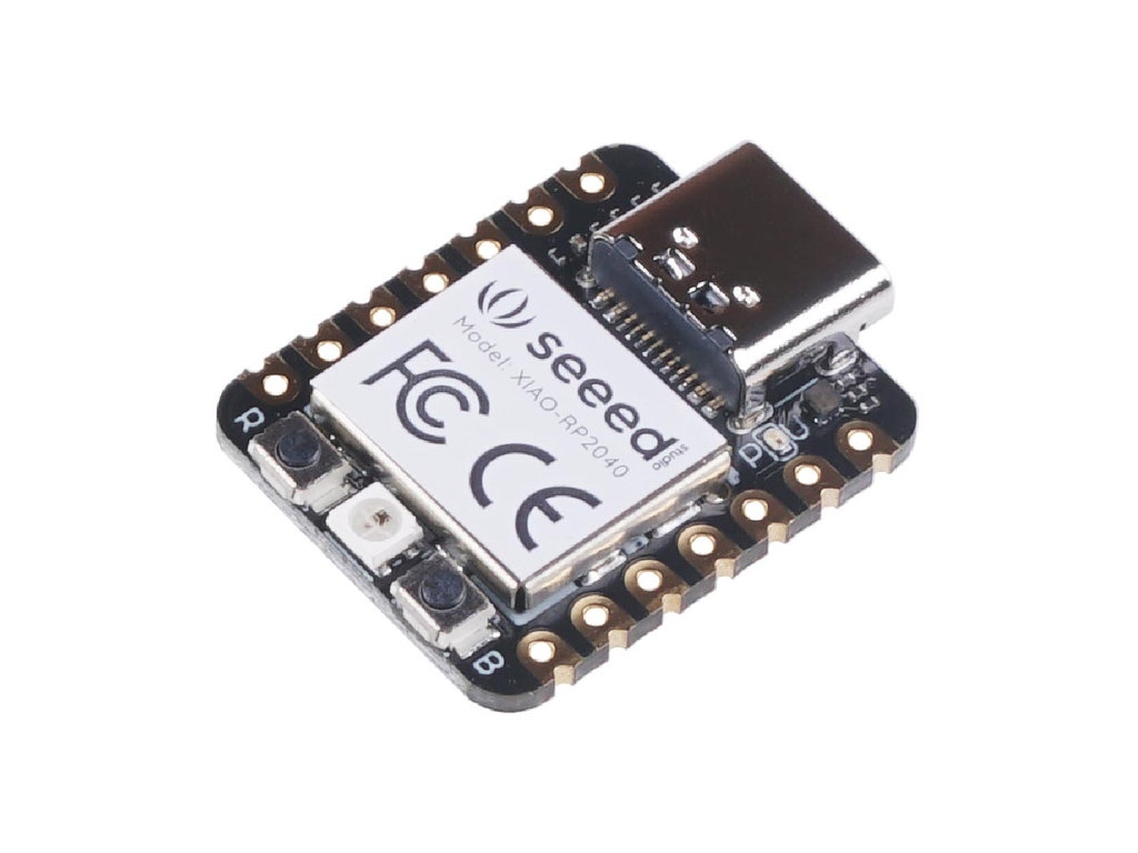
1. MCU — Seeed Studio XIAO RP2040
Pins D0–D7 are used as follows: D0/D1 for Motor A direction, D2/D3 for Motor B direction, D4/D5 for SDA/SCL (LCD + MPU6050), D6 for LED, and D7 (RX) to receive the signal from the face detection PCB.
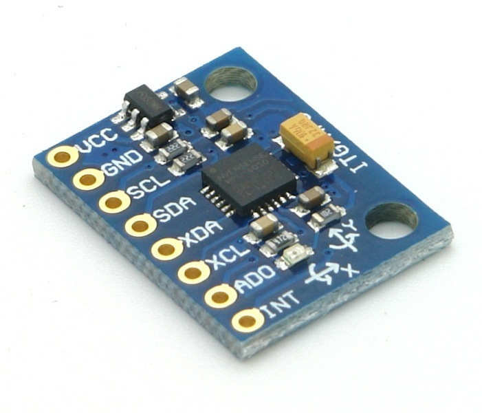
2. Sensor — MPU6050
The MPU6050 is the "gold standard" for balancing projects — it combines a 3-axis accelerometer (tells the robot which way is down) and a 3-axis gyroscope (tells how fast it is falling), with 16-bit ADC for detecting very small movements.
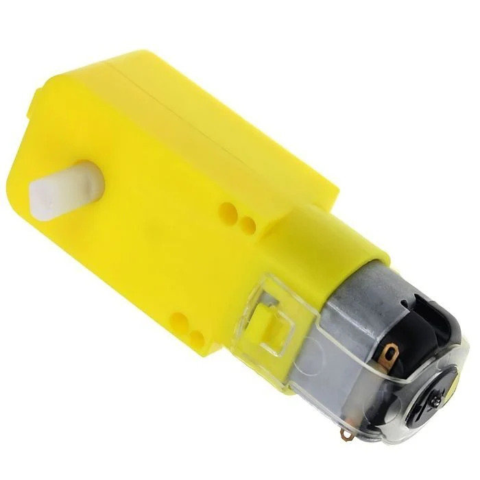
3. Motors — 2× TT DC Gear Motor (3–6V)
This is a compact and convenient option
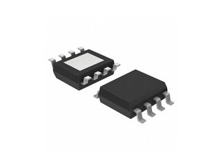
4. Motor Drivers — 2× A4953
The only motor driver available in the lab; its minimum voltage is 8V, which is not ideal for lower voltages.
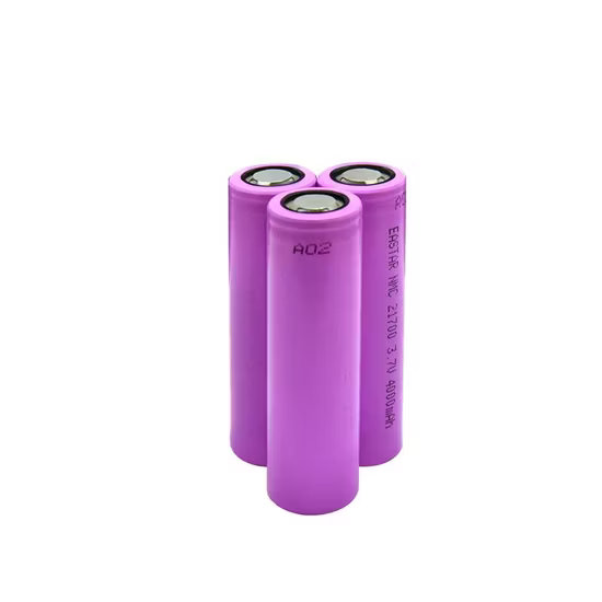
5. Battery — 3× 1200mAh 4.2V Li-Po
Compact, easy to use, and enough to power both motors and the MCU for the camera.
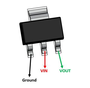
6. Voltage Regulator — LM2940
Sensitive to noise, so a 22µF capacitor is used to keep the 5V rail stable.
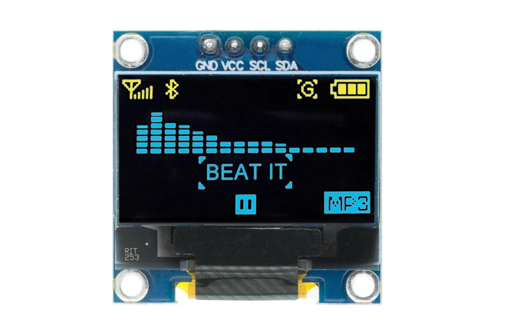
7. Display — OLED SSD1306 (I²C)
Compact size and multiple colors allow nice animations.
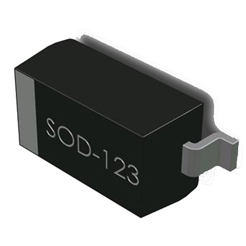
8. Diode — Schottky Diode SOD123
Placed near the 5V line so that when powering from battery, USB current won't damage the MCU.
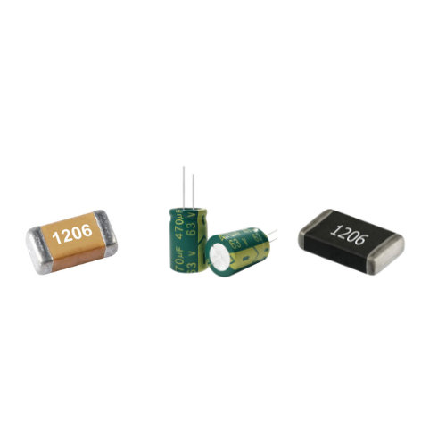
9. Resistors & Capacitors
For proper configuration and to avoid short circuits.
🗺️ Main Robot — Schematic and PCB Design
With all components and their purposes defined, the KiCad schematic and PCB designs were assembled.
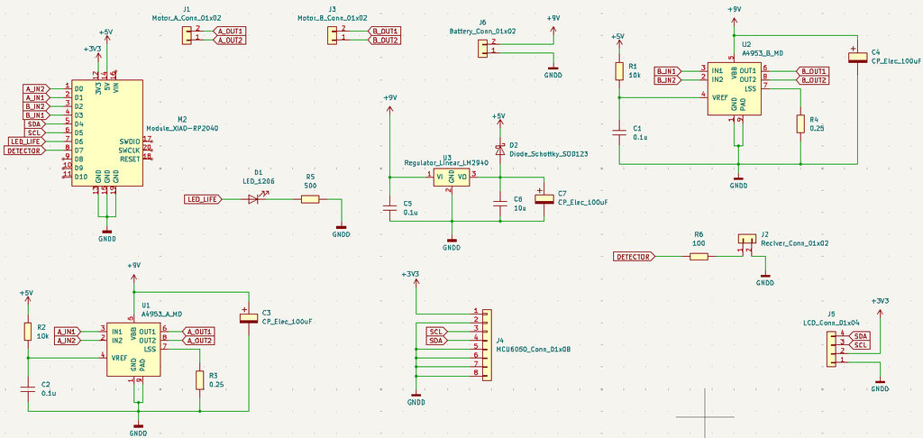
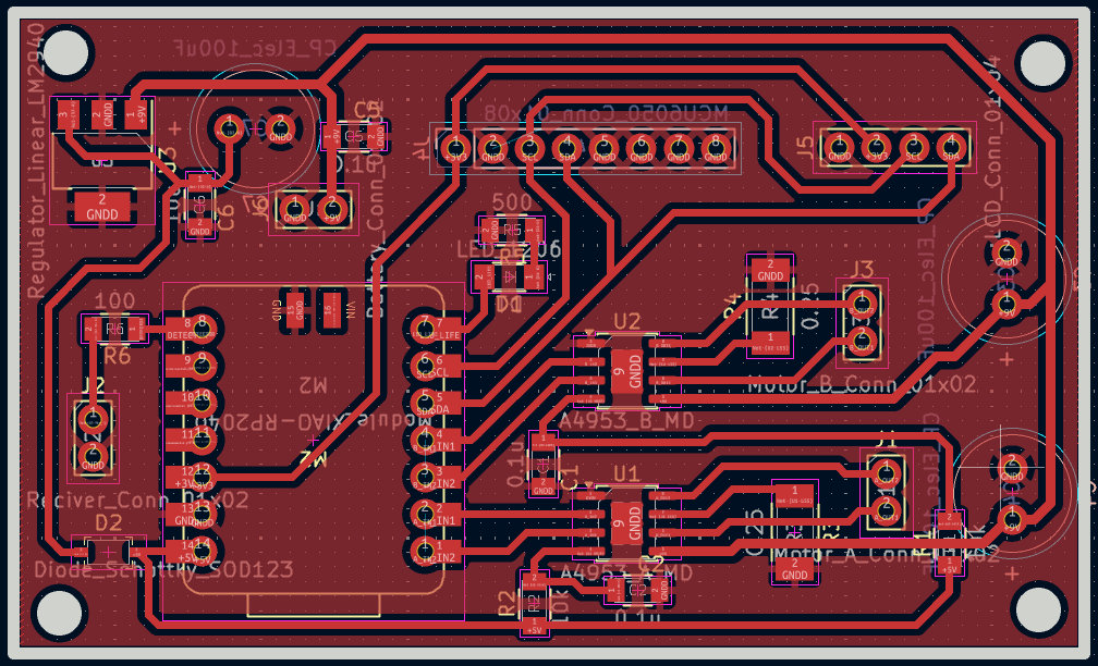
3D views of the PCB:
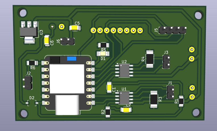
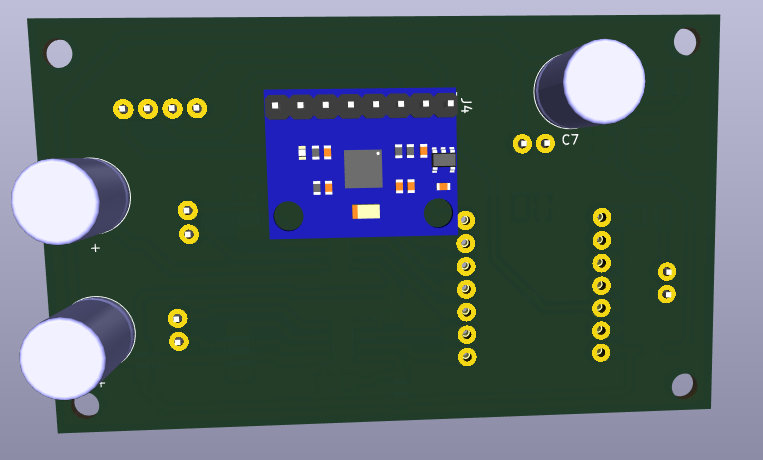
Once the files were ready, .nc files were generated on modsproject.org for F.Cu (1/64” bit) and Edge.Cuts (1/32” bit).
🔧 Main Robot — Soldering
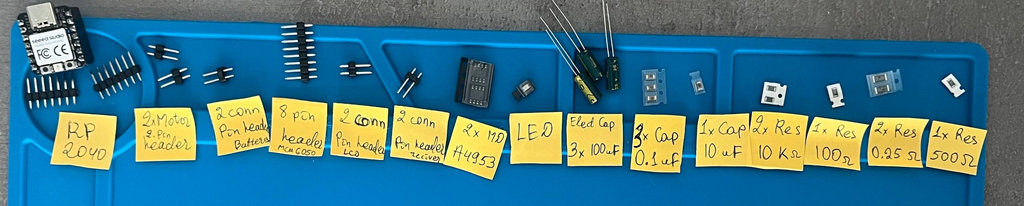
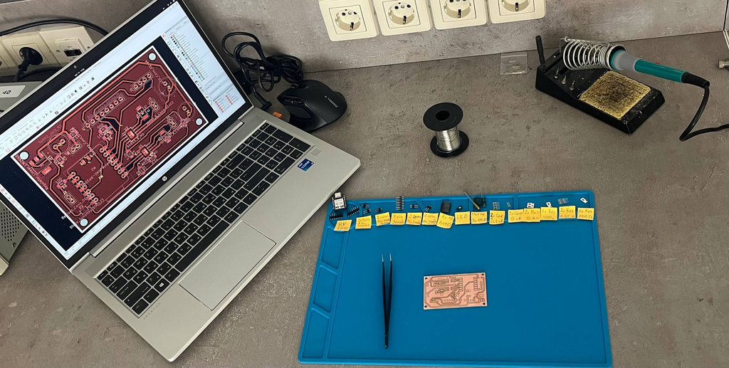
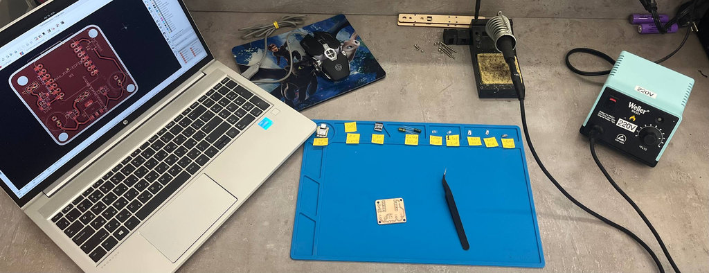
All components laid out and workspace prepared:
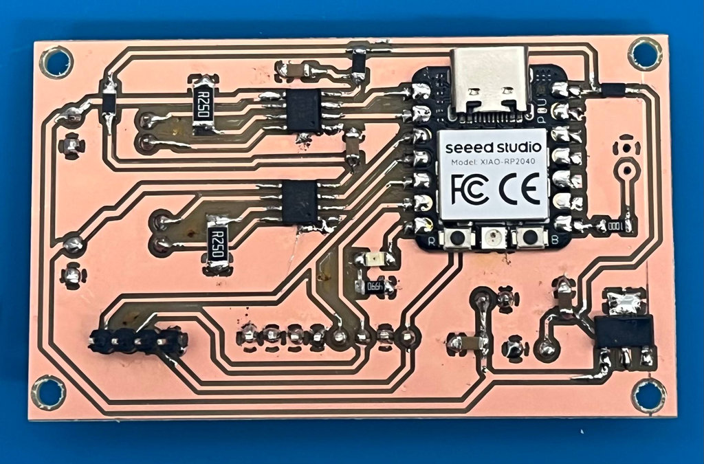
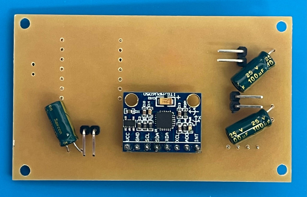
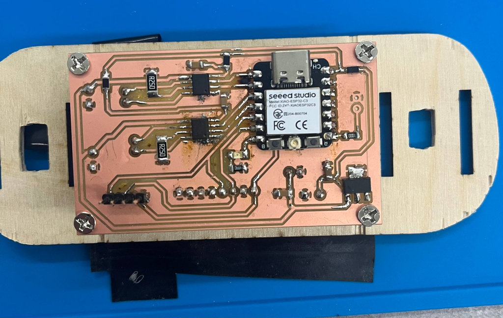
Final soldered result (top and back):
🧠 Main Robot — Programming & PID Control
The first test code initialized the MPU6050 and OLED and drove the motors forward — but without a closed-loop system the robot cannot balance. A balancing robot is like keeping a stick on your finger: without continuous correction it falls.
The robot needs PID control — a smarter brain that runs every few milliseconds:
| Term | Formula | Role |
|---|---|---|
| 🟢 P (Proportional) | Kp × error |
Reacts to current tilt |
| 🟡 I (Integral) | Ki × Σ error |
Fixes long-term drift |
| 🔵 D (Derivative) | Kd × Δerror/Δt |
Reacts to how fast it is falling |
motor speed = P + I + D — recalculated every few milliseconds.
Video of the first test (MPU6050 + OLED + motors, open loop):
With Hrach’s help a temporary body was built for testing. Here are the first videos of the robot falling 🤪:
After several tests, the SDA pin of the RP2040 burned out. The MCU was replaced with an ESP32-C3 (same pin functions), and Onik helped further stabilize the system.
😄 Smile Detection Module
Research
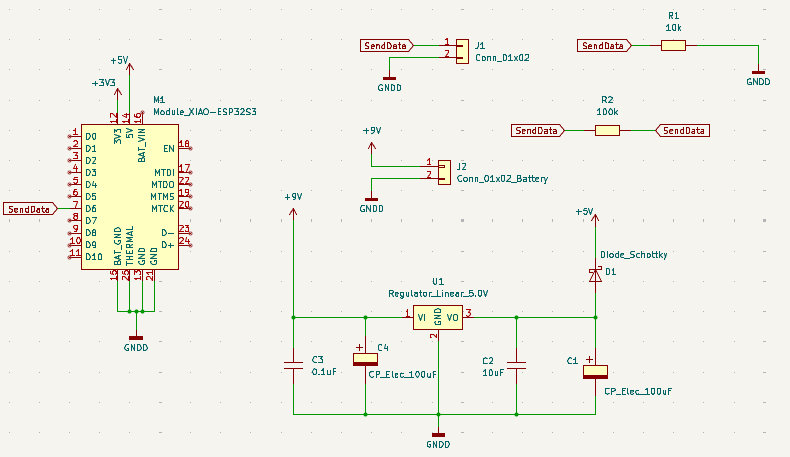
The XIAO ESP32-S3 Sense was chosen as a vision co-processor — it focuses entirely on the camera stream and smile detection, and communicates to the main MCU via a single GPIO pin (PIN 43: HIGH = smile detected, LOW = no smile).
Electronics — Smile Detection PCB
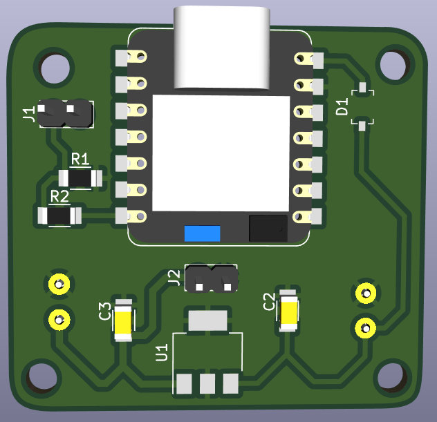
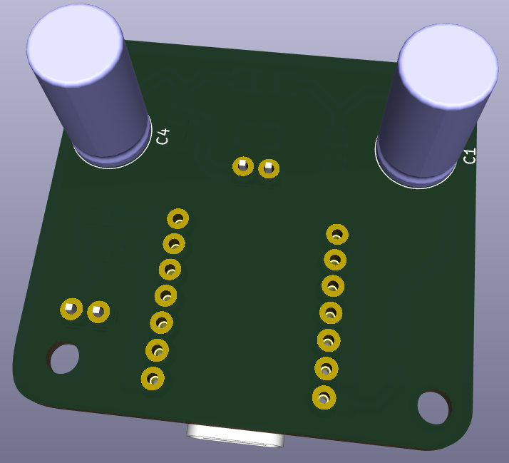
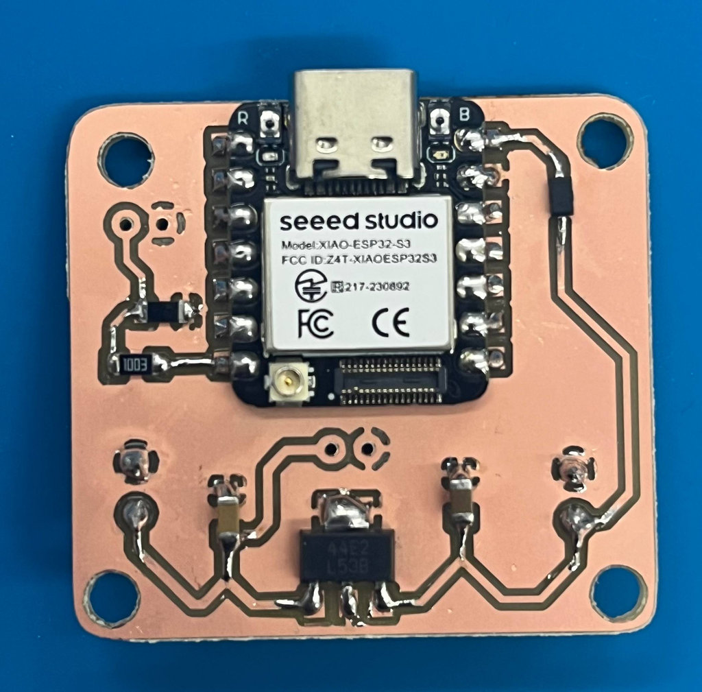
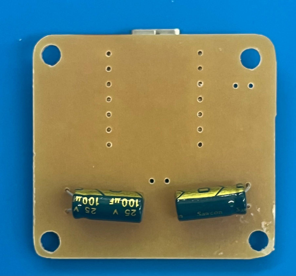
Components: ESP32-S3, LM2940 voltage regulator, capacitors and resistors. The PCB was also designed in KiCad.
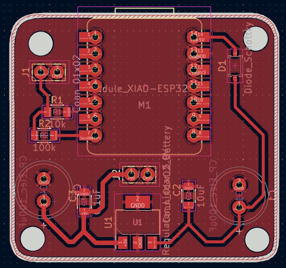
3D views:
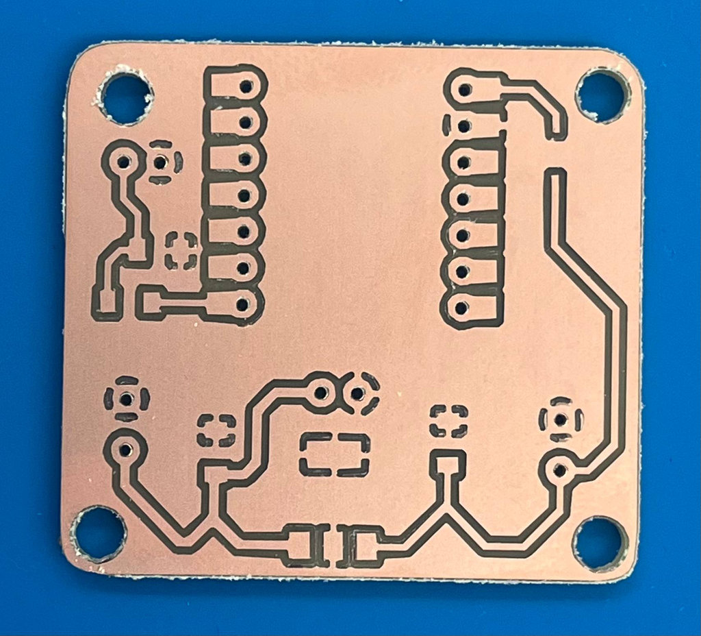
Soldering — Smile Detection

When attaching the ESP32-S3, double-sided tape was used under the chip to prevent its back copper layer from shorting with the PCB GND.
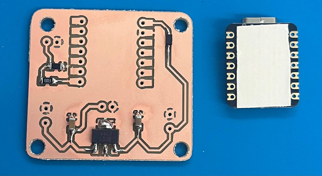
Final result:
Programming — Smile Detection & Web Interface
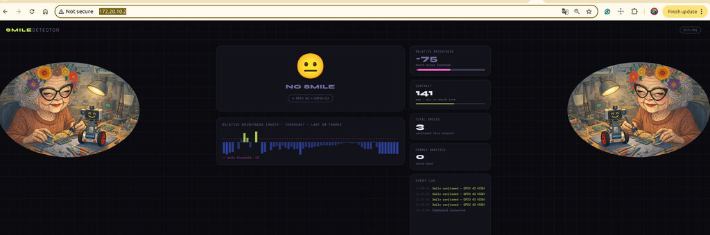
The smile detection algorithm is brightness-based (grayscale, no face detector). It compares a forehead zone (top 10–25% of frame) against a mouth zone (62–85%). If the mouth is significantly brighter (teeth visible) and local contrast is high enough, a smile is counted. A web dashboard served from the ESP32-S3 shows the live brightness chart, contrast meter, total smiles, and GPIO 43 status in real time.
Web interface screenshot:
Smile detection demo video:
Limitation: zones are hardcoded as fixed frame percentages, so detection only works when the person is centered at a specific distance. Any position change breaks the detection — the algorithm doesn’t know where the face actually is.
🧪 Person Classification — Edge Impulse Experiment
After the brightness-based approach proved unreliable, a custom ML model was built using Edge Impulse to classify between Mariam and Hrach.
A Python + OpenCV script auto-captured 100 face photos per person via webcam, saved into dataset/Mariam/ and dataset/Hrach/.
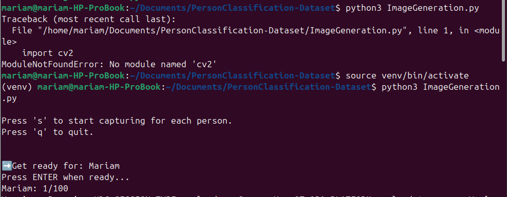

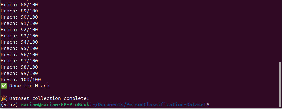
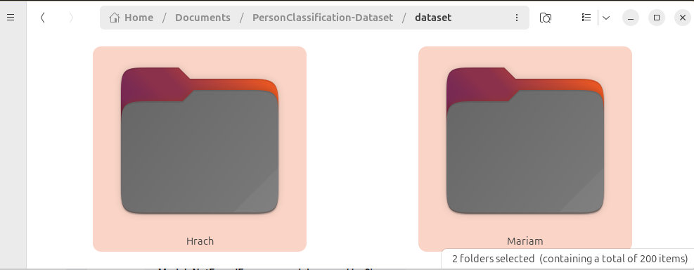
The dataset was uploaded to Edge Impulse → an Impulse was created (Image input → Classification) → features generated → model trained.

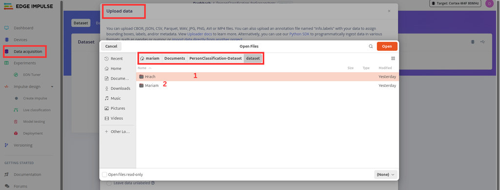
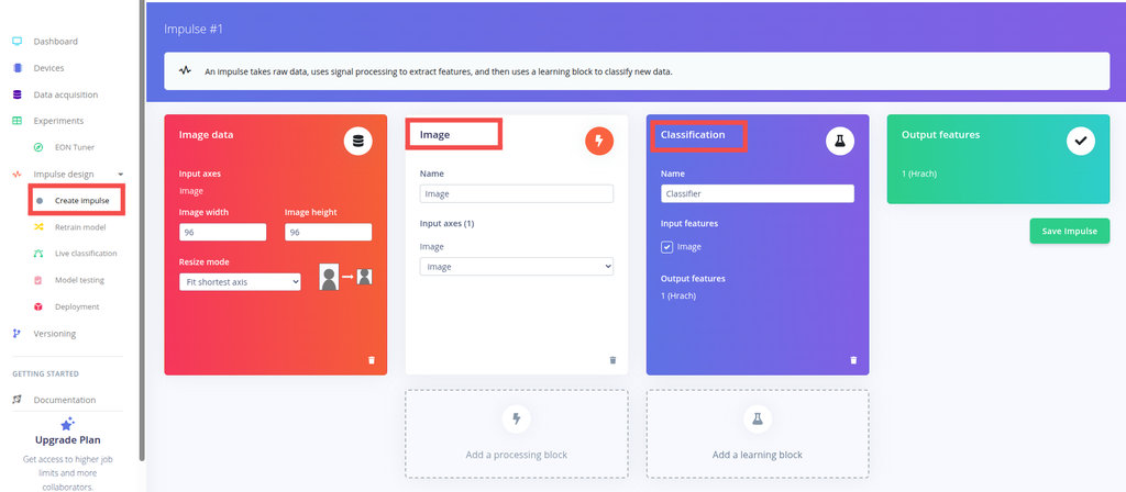
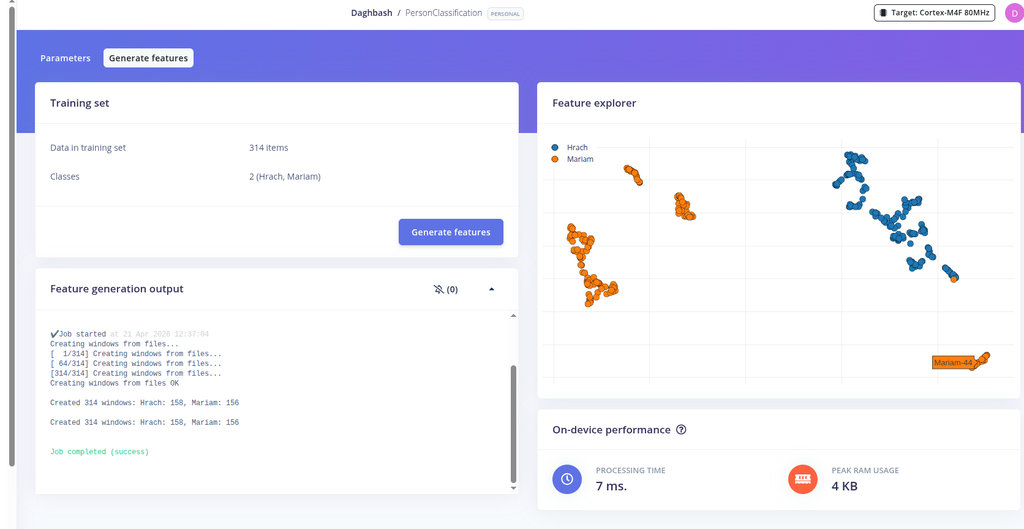
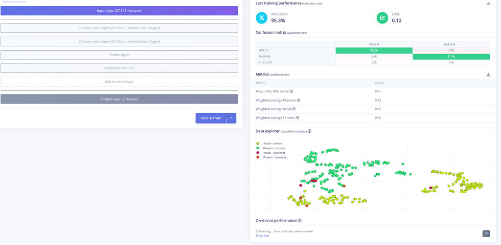
Model testing showed 91.36% accuracy on the test set:
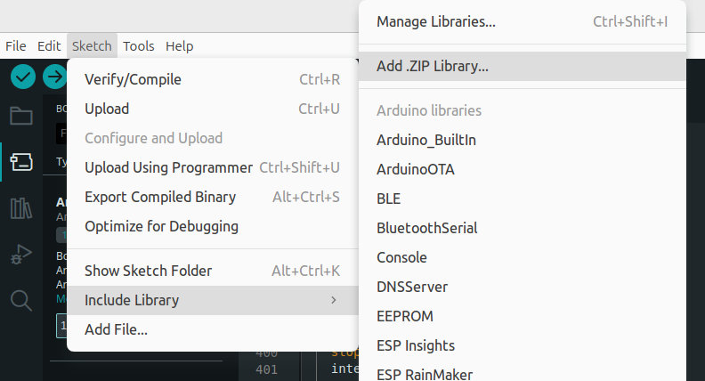
The model was deployed as an Arduino Library (.zip) and installed via Sketch → Include Library → Add .ZIP Library.
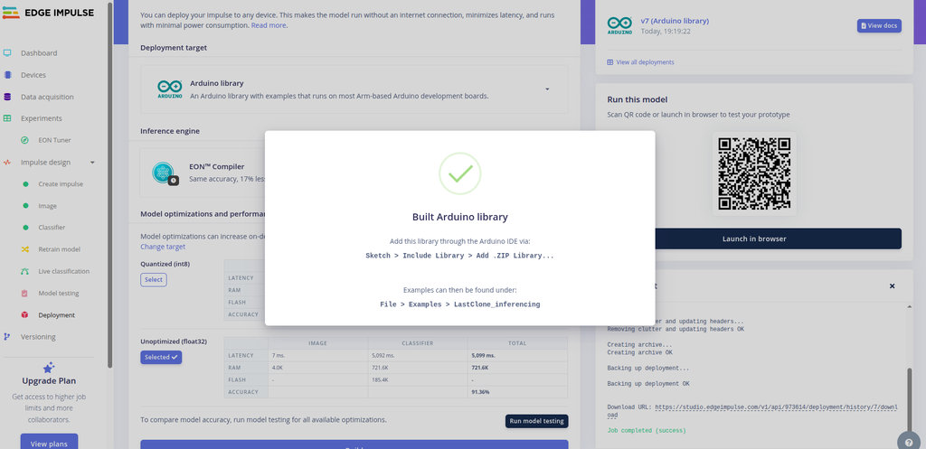
Real-world result: the model recognized Hrach as Mariam, and almost any object as Hrach. The dataset of 100 images per person was far too small. 😄
👤 Face Detection — Final Approach
Returning to basics: the camera only needs to detect that a person is present, not recognize who. Two built-in ESP-DL models run directly on the ESP32-S3:
HumanFaceDetectMSR01— fast first-pass candidate detectionHumanFaceDetectMNP01— refines candidates with a confidence threshold
Logic: Face detected → PIN 43 HIGH → ESP32-C3 stops balancing motors. No face for 1.5 s → PIN 43 LOW → robot resumes. Green bounding boxes are drawn around detected faces and the live web interface shows camera feed + detection stats.
🏁 Final Robot with Interface
After many PID coefficient adjustments and code modifications, here is the final result. The robot balances and stops when a face is detected. The balancing is not yet perfect, but the full pipeline — PCB design, milling, soldering, PID control, and computer vision — was completed in one week.
Hrach’s Individual Contribution — Self-Balancing Robot
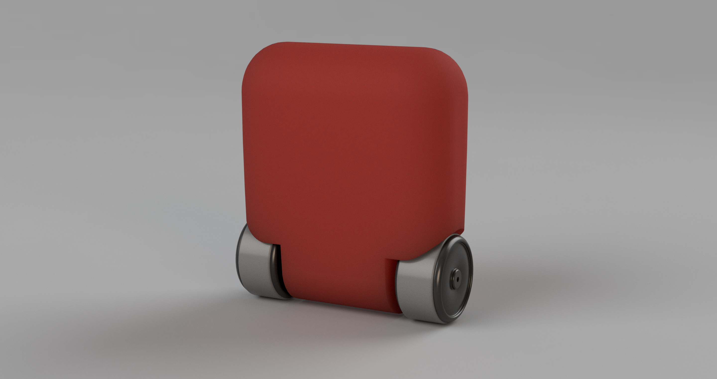
*Rendered model of the robot.
The Design
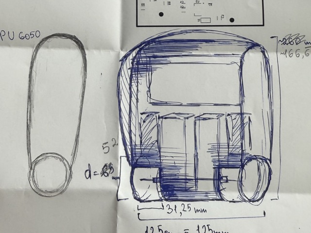
We began by each submiting a draft of what the robot would look like, and after ideating a day, we landed on this sketch. We had decided to place the batteries somewhere in the upper part of the body to raise the center of gravity. If it were lower it would have been more difficult for the robot to try to balance itself.
The Components
1x chassis
2x rims
2x tires
2x DC motors
1x ESP32-C3 for mobility
1x ESP32-S3 for camera input
1x LCD
1x camera
1x Wi-Fi antena
1x infinate patience
Wheels
Everything began from a single tire and a rim. The rim was simple, printed with black PLA. Whereas for the tire, initally, we wanted to print it with transparent TPU, but ended up switching to a different color filament.
The Tire
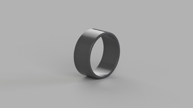
When choosing the infill pattern, I was aiming to provide cushioning that mimics the behavior of a pneumatic tire. However, the robot was not heavy enough, and the tire walls were not thin enough to create any suspension. Despite the stiffness, the TPU provided sufficient traction, effectively preventing slips.
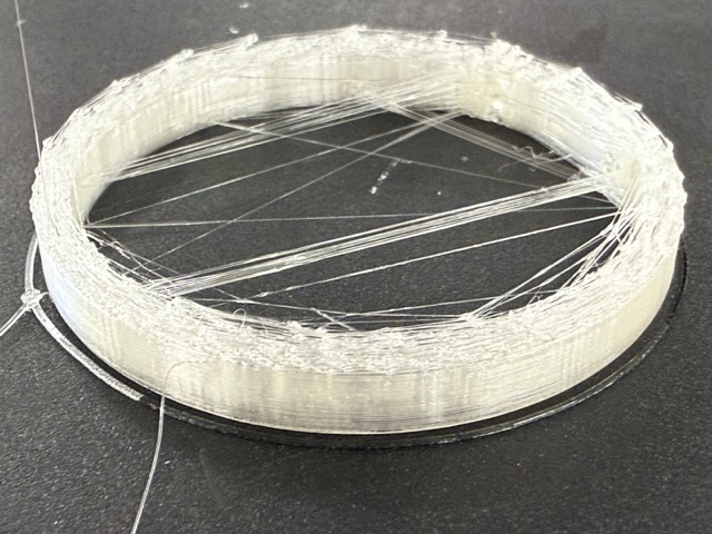
The first attempt to print the tires did not go as planned. The lower layers turned out fine, but as it would progress through the print, the layers would get ruined. Assuming the nozzle was clogged, so we tried cleaning it. The needle did not work so we tried some other methods, such as heating the nozzle, and retracting the filament by pulling with a quick movement.
Eventually, we came to a conclusion that the fault was with the filament. So we switched to an opaque silver metallic TPU [shown below].
The Rim
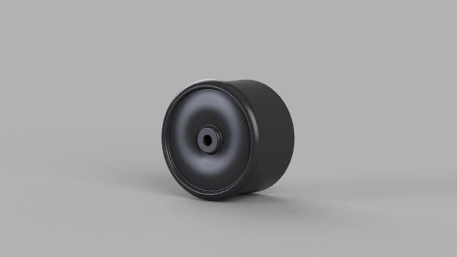
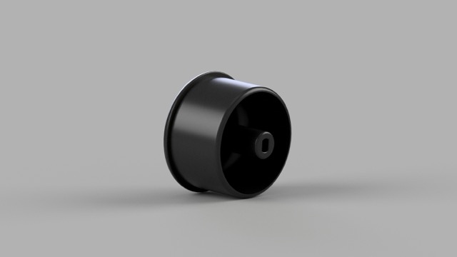
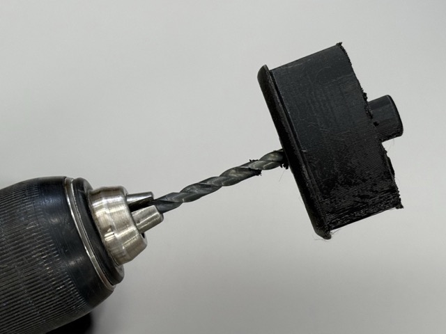
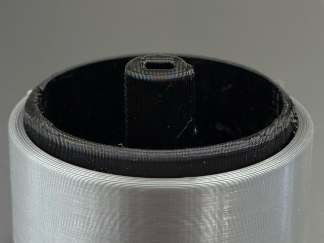
In the final 3D model shown below, I included a hole for the screws that attach the wheels to the motors, while the short, wide opening accommodates the motor shaft.
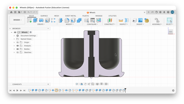
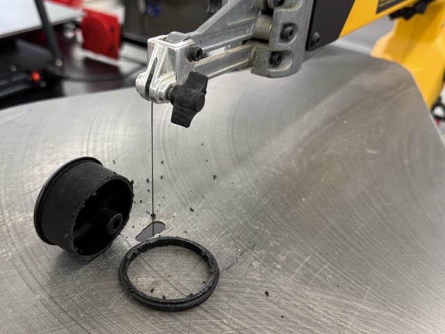
The design evolved after I realized the screw length exceeded the rim depth [right image below]. Furthermore, the rigid TPU tires were nearly impossible to remove without damaging the rim with metal tools. After trimming the inner rim with a scroll saw [left image below], I iterated the design into the current version of it [larger image below].
Inner Structure
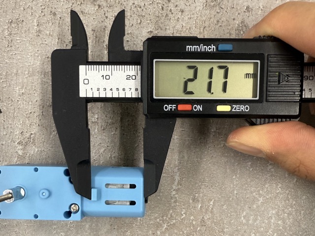
Meanwhile, I had also taken all of the component measurements, and created their digital twins in Fusion. This was done to create the 3D version of the insides, and understand how to organize, and fit the comonents to achieve the best balance for the robot.
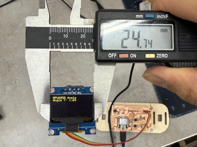
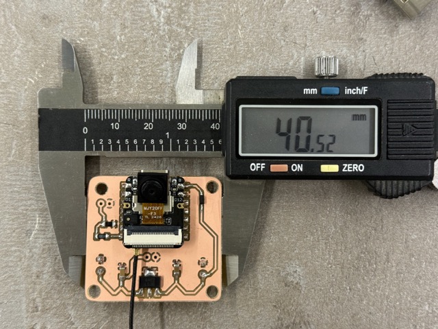
Not sure why, but I did not download 3D files of the motors, display or other parts. But throughout designing each component I noticed a significant advance in CAD designing. I also later learned that I could dowanload the 3D versions of the PCBs from KiCad.
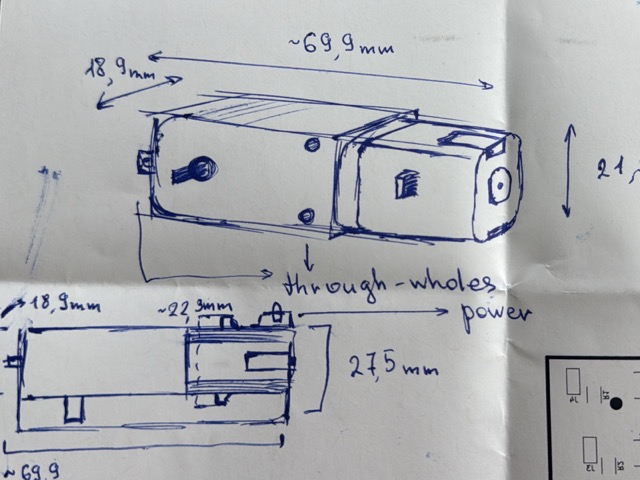
For example, in this image below, based on the measurements of the motor, I designed a pocket where the motor would fit with minimal space to wobble.
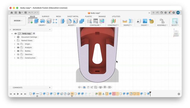
Chassis
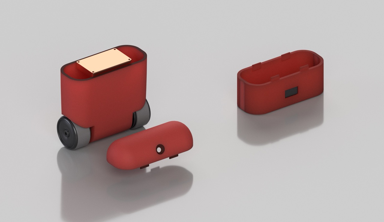
Our filament of choice was red transparent PETG. Compared to the body rendered body [much further image below] the translucency is more visible. We planned to print this version when we were sure that the robot would work as anticipated, but when the moment came to test the red filament, we realized that it would not print good. After all, the total print time was near 12 hours.
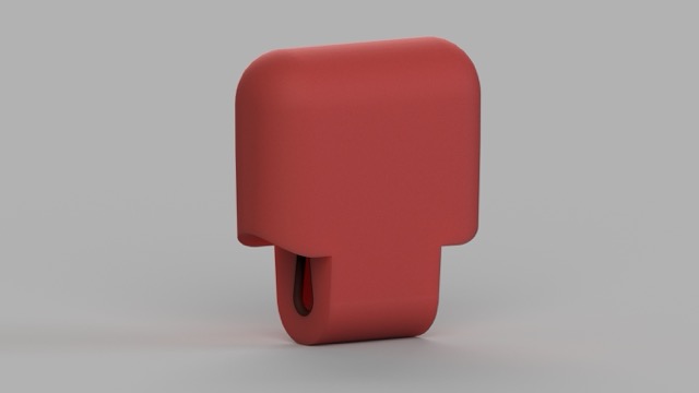
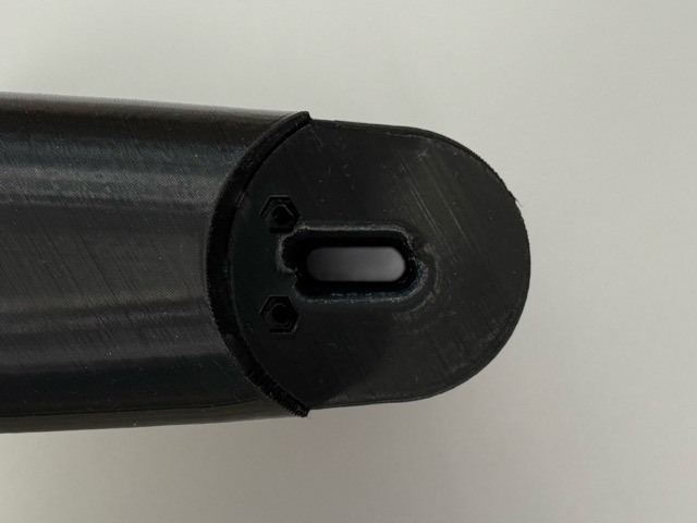
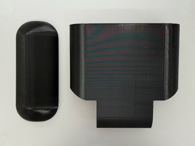
We tried drying the filament, cleaned the nozzles, changed print settings, we even changed the printers. As nothing seemed to work, we ended up not switching the housing, and left in it’s second, black print prototype.
Camera
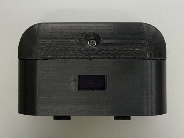
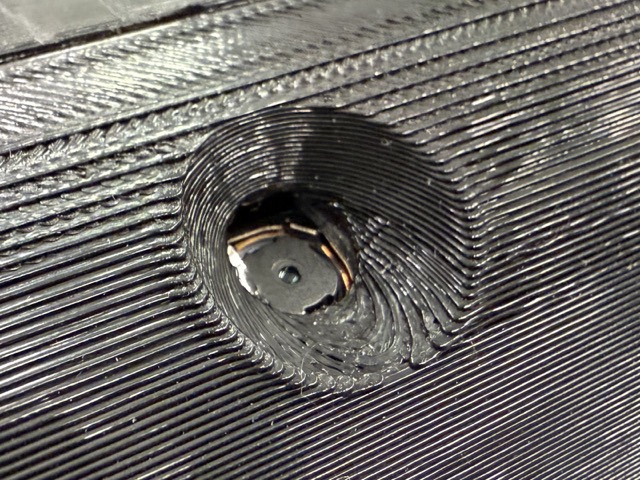
The camera whole was left so wide as I was not very sure how wide the angle of the lense is, but the camera we used was XIAO esp32 S3’s camera module.
Charger
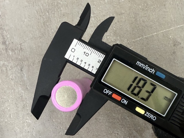
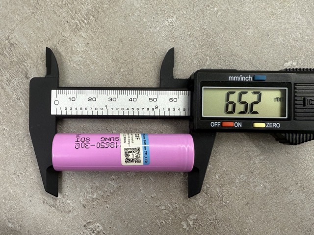
Separetly, we considered having a separate battery charger, as opposed to having a battery management system [BMS] taking up more space in the robot. Nevertheless, from our point of view, this was a smart approach as we wouldn’t know how many times we’d need to disassamble the robot throughout development.
I havn’t experienced this, but I do not recommend either! Do not use a metalic caliper to meature a batter, especially tocuhing the anode and the cathode.
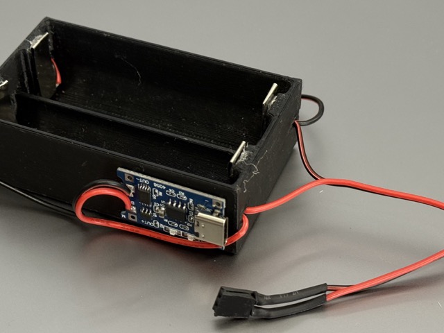
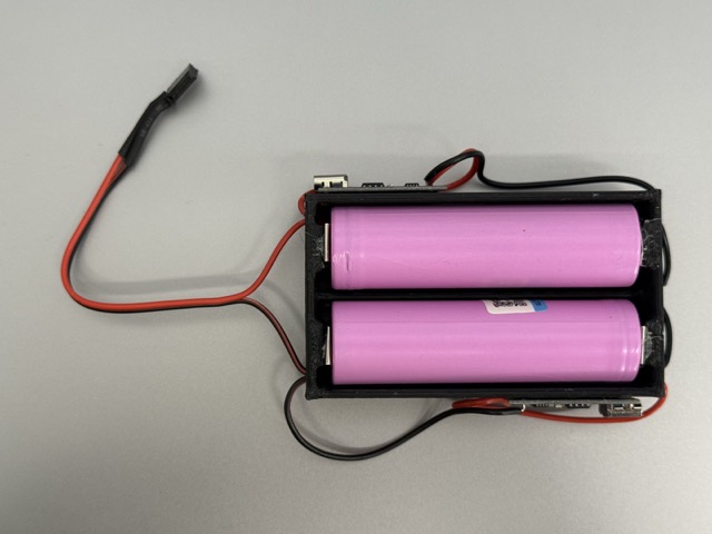
Prototype
As the robot is meant to continuously wobble, even when prototyping we quickly advanced from having a rubber band setup, to having the PCB screwed onto the plywood panel.
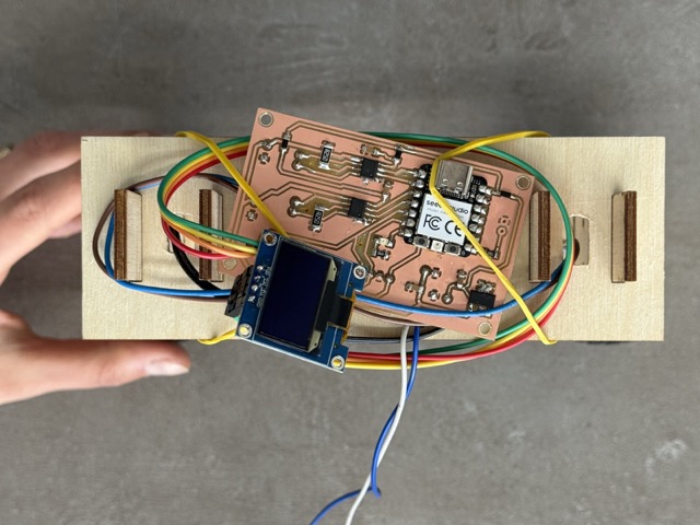
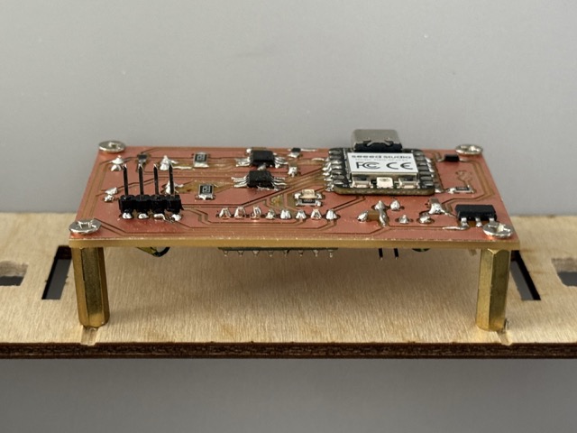
Frame
The draft version of the robot had two laser-cut plywood legs for which we had separetly designed a plastic cube that would pass the motor wires through, and create a stable support for the upper part of the structure.
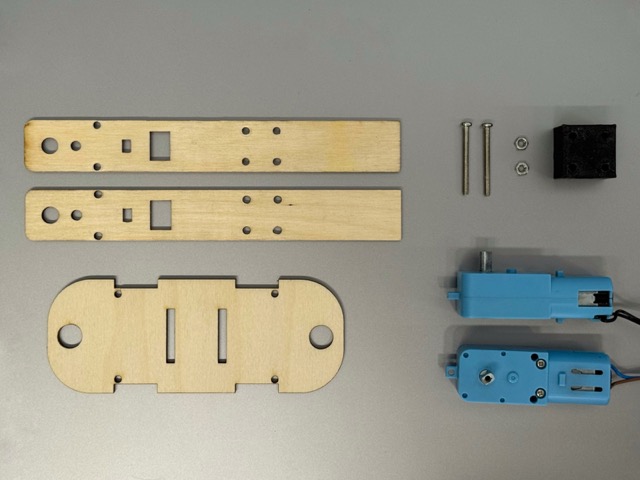
Results
As we had decided on what will be inside the printed body, we also decided not to change the inner architecture. This would both save time on designing, and printing. So a workaround was reinforcing the insides by having a one of the sets of thee legs as a central core to the robot.
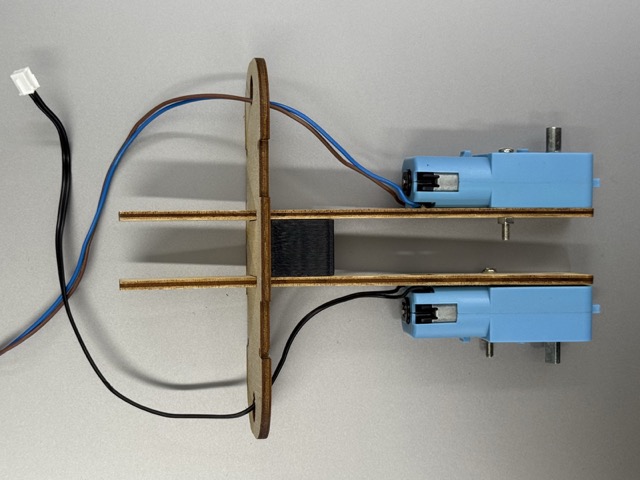 *The skeleton.
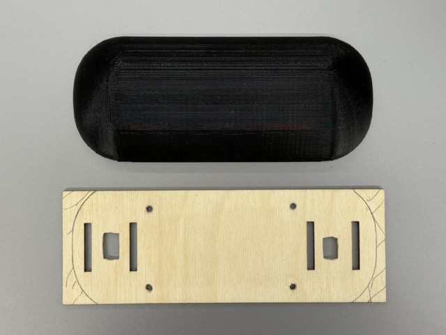
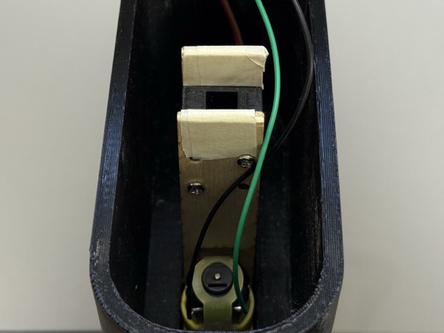
Design Improvments
In order to save time, I had simplified the joints, which are not very good. They simply hold the body parts together. In my initial design I wanted to have a back door to the body, and not a body that would disassamble to multiple parts. So the major change would be this.
Conclusion & Future Developement
The week ended up being more than I expected. I spent a lot of time in Fusion 360 – more than I have ever before – and looking back, the improvement in my CAD skills was one of the biggest wins of the whole week. There’s something about choosing a hard problem that pulls more out of you than an easier one would. It also changed how I think about the final project — now I feel like I can’t go backwards. Whatever comes next has to be at least as interesting as this, if not more.
For us, not only the purpose of this project was to balance a robot on its two wheels, but also a big takeaway was the learning. As for what comes next to this project, I think to improve its stabalizing, which will result in further learning.
📁 Files for Download
| File | Description |
|---|---|
| Self Balancing Robot — Balancing Part | KiCad PCB — ESP32-S3 self balancing board |
| Self Balancing Robot — Balancing Part | SVG’s — Self balancing board |
| Self Balancing Robot — Smile Detection Part | KiCad PCB — Smile Detection board |
| Self Balancing Robot — Smile Detection Part | SVG’s — Smile Detection board |
STL
• Rim
• Tire
• Motor
• Body
• Battery Holder
3MF
• Rim
• Tire
• Motor
• Body
• Battery Holder
F3D
• Rim
• Tire
• Motor
• Body
• Battery Holder