12. Mechanical Design, Machine Design
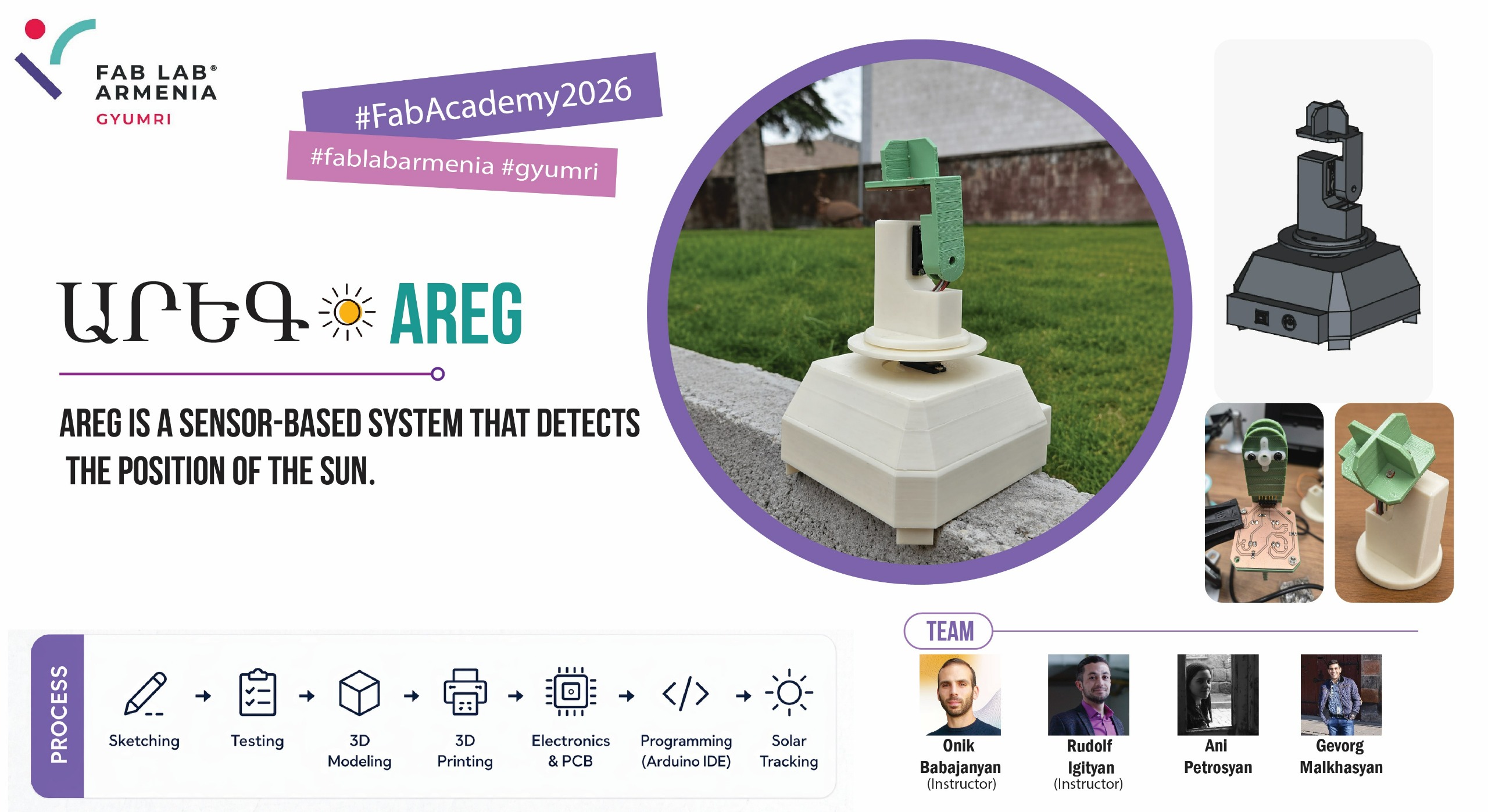
Details can be found on our group page.
Idea
The idea of the Solar tracker was given by our Fab Academy instructor at Fab Lab Dilijan, Onik Babajanyan. Since Armenia is a sunny country, we liked his suggestion. If we obtain an efficient solar tracker, we will be able to get maximum energy from the sun throughout the year. We began studying the types of solar trackers based on their operating system:
- LDR Based Solar tracker LDR photoresistors are used in its construction; it determines the direction of the sun based on light intensity. It is simple, cheaper, and suitable for an educational project.
- GPS Based Solar Tracker GPS is used; it calculates the time and location data, and determines the position of the sun based on the location. It is very accurate and does not depend on light sensors, but it is more complex from a programming perspective.
- Hybrid Solar Tracker It combines several methods; it is the smartest option and has the highest accuracy, as it uses GPS and LDR sensors, a dual-axis system, and calculations based on various algorithms. However, it is the most complex in its structure.
Based on our research, it became clear that the best option for us is the LDR Based Solar Tracker with a dual-axis system.
Light Sensor Selection
A photoresistor (LDR) changes its resistance depending on the amount of light hitting it, which makes it a good fit for this task. To read its value with a microcontroller, we needed a voltage divider: a fixed resistor in series with the LDR, with the analog pin connected at the midpoint between them. This way, the analog reading changes with the LDR’s resistance instead of just showing a fixed 5V or 0V.
Since the LDR’s resistance drops in brighter light, the voltage across it also drops — so lower analog values mean more intense light. Putting the fixed resistor closer to GND instead of 5V would flip this to a direct relationship.
Choosing the Right Fixed Resistor
Rather than picking a resistor value off the internet, we measured the LDR’s resistance ourselves in two conditions:
- Room light: ~1250 Ω
- Covered (dark): ~20000 Ω
We then compared two candidate resistors, 1 kΩ and 10 kΩ, using the voltage divider formula to calculate expected analog readings (0–1023) in both light and dark conditions for each.
| Condition | R1 = 1 kΩ | R1 = 10 kΩ |
|---|---|---|
| In light | ~568 | ~114 |
| In darkness | ~975 | ~682 |
| Spread (dark − light) | 407 | 568 |
We went with the 10 kΩ resistor. It gives a wider spread between light and dark readings, and the threshold lands near the middle of the 0–1023 scale, which makes calibration easier.
Schematic Design
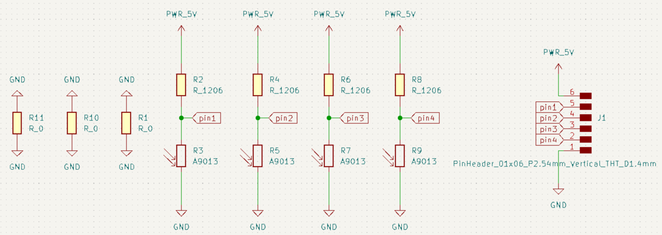
The schematic was made in KiCad, with four identical voltage divider channels — each pairing a 10 kΩ resistor (to 5V) with a photoresistor (to GND), feeding the midpoint to one of four analog pins.
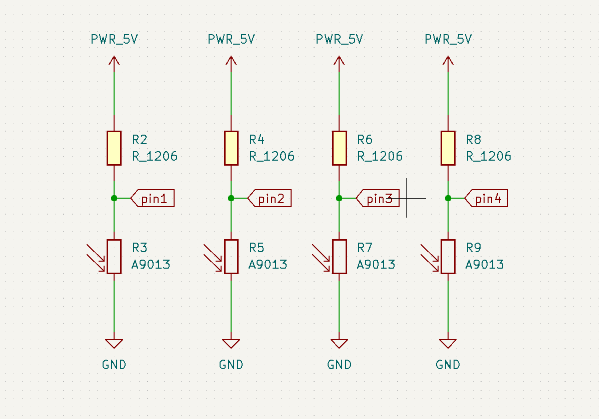
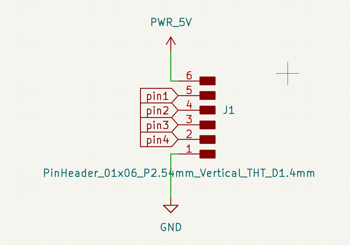
All four channels share power through a single pin header, which also exposes the four analog signal pins to the microcontroller.
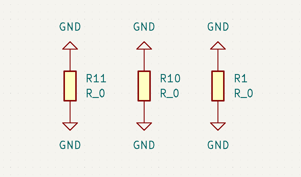
Some traces couldn’t be routed without crossing, so we added three 0 Ω resistors as jumpers to bridge them on the single-layer board.
The final schematic:
PCB Design
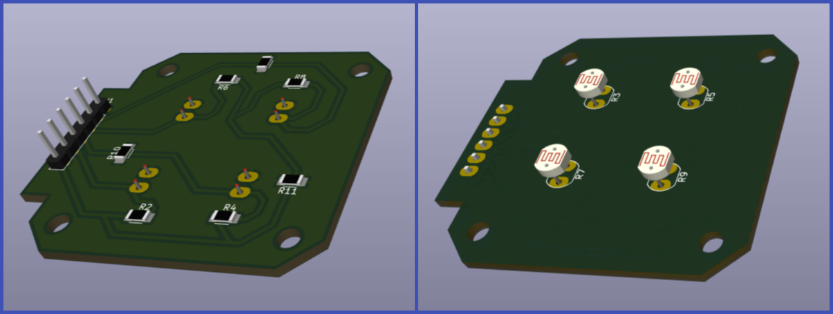
The layout was also done in KiCad, with the four photoresistors placed symmetrically. They sit on the back of the board on purpose — the PCB mounts to the enclosure from the back, so the sensors end up flush against the divider walls.
Signal traces were kept short to reduce noise, and 5V/GND were routed across the board for stable power to all four channels. Mounting holes were added at the corners for screw attachment.
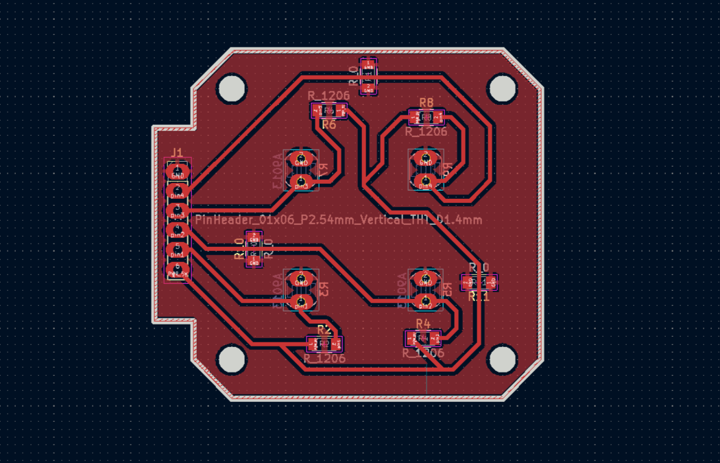
We checked the board in KiCad’s 3D viewer before exporting, to confirm component placement and overall geometry.
G-code Generation
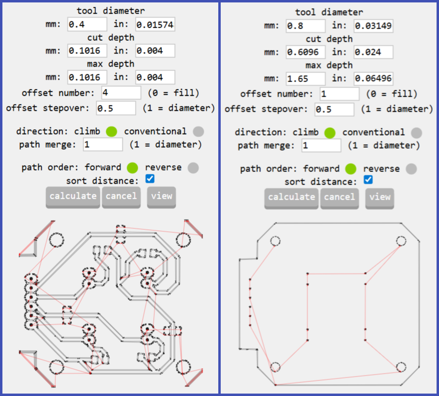
Toolpaths were generated with mods.cba.mit.edu. We exported two SVGs from KiCad — one for the copper traces, one for the outline and holes — and processed each separately into two NC files: a 0.4 mm trace isolation pass and a 0.8 mm outline/drilling pass.
Milling and Soldering
The two NC files ran sequentially on the Roland SRM-20. The copper-clad FR1 board was fixed to the bed, zeroed, and milled — traces first, then outline and holes. After milling, all components were soldered except the photoresistors — those were left for later, soldered only after the board was mounted on the enclosure, so each sensor would line up exactly with the divider walls.
Servo Motor Selection
For the vertical and horizontal rotation, we compared two servo motors: the HK-15138 standard analog servo and the Corona DS-939MG digital metal gear servo.
| Feature | HK-15138 | Corona DS-939MG |
|---|---|---|
| Motor Type | Standard analog | Digital metal gear |
| Operating Voltage | 4.8V – 6V | 4.8V – 6V |
| Torque | ~4.3 kg·cm | ~2.5–2.7 kg·cm |
| Current | ~0.7–1 A | ~0.2–0.24 A |
| Speed | ~0.17 sec/60° | ~0.13–0.14 sec/60° |
| Gear Type | Plastic | Metal |
| Weight | ~38 g | ~12.5 g |
We picked the Corona DS-939MG. Its ~2.5–2.7 kg·cm torque is enough to rotate a 250 g load at a 10 cm arm length, and we wanted to keep the device lightweight.
Servo Motor Test
We cut a 150 mm plywood disc on the laser cutter to test the servo under load, attached it, and connected everything to an Arduino UNO.
We used the standard Arduino servo sweep example to move it continuously from 0° to 180° and back:
Then we added weights to simulate real conditions:
The total weight of the upper structure came to about 805 grams.
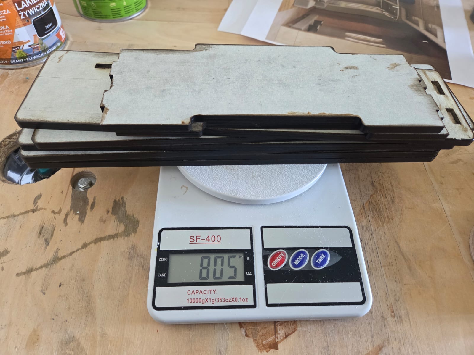
We also tested the load suspended vertically:
The servo held up well under both load configurations, confirming it was suitable for the sun tracker. The Corona DS-939MG also let us skip an external power supply — a single servo draws about 200 mA, and since both motors don’t run at the same time, total current stays within the 500 mA the Arduino UNO can supply through its 5V pin.
3D modeling
Initial sketch
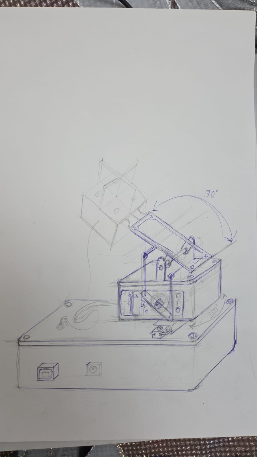
After discussing the initial sketch, and taking into account the requirements set before us, the model had to be designed accordingly:
- as lightweight and compact as possible
- the wires and mechanisms had to operate inside it without any obstruction
- the wires would not be visible
Final sketch
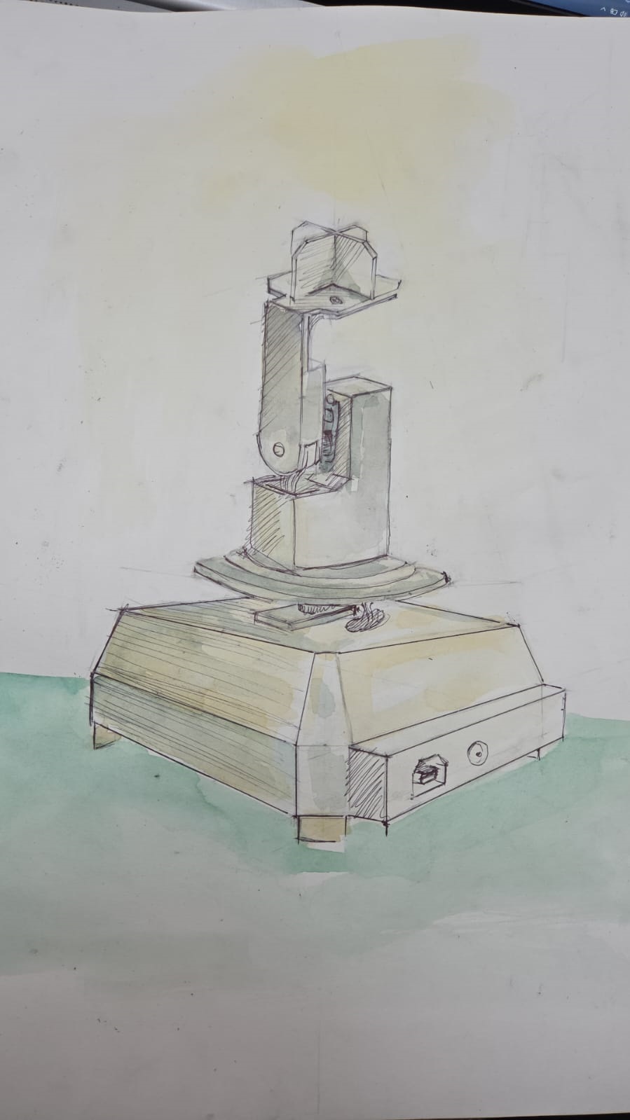
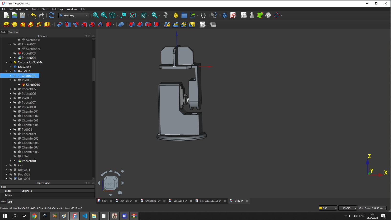
Based on this sketch, we started our 3D modeling phase and divided the work into two parts. Ani will model the section where the Arduino Uno and the horizontally operating motor will be placed, while I will design the part that will be mounted on the motor shaft, through which the wires will pass and reach the vertical motor.
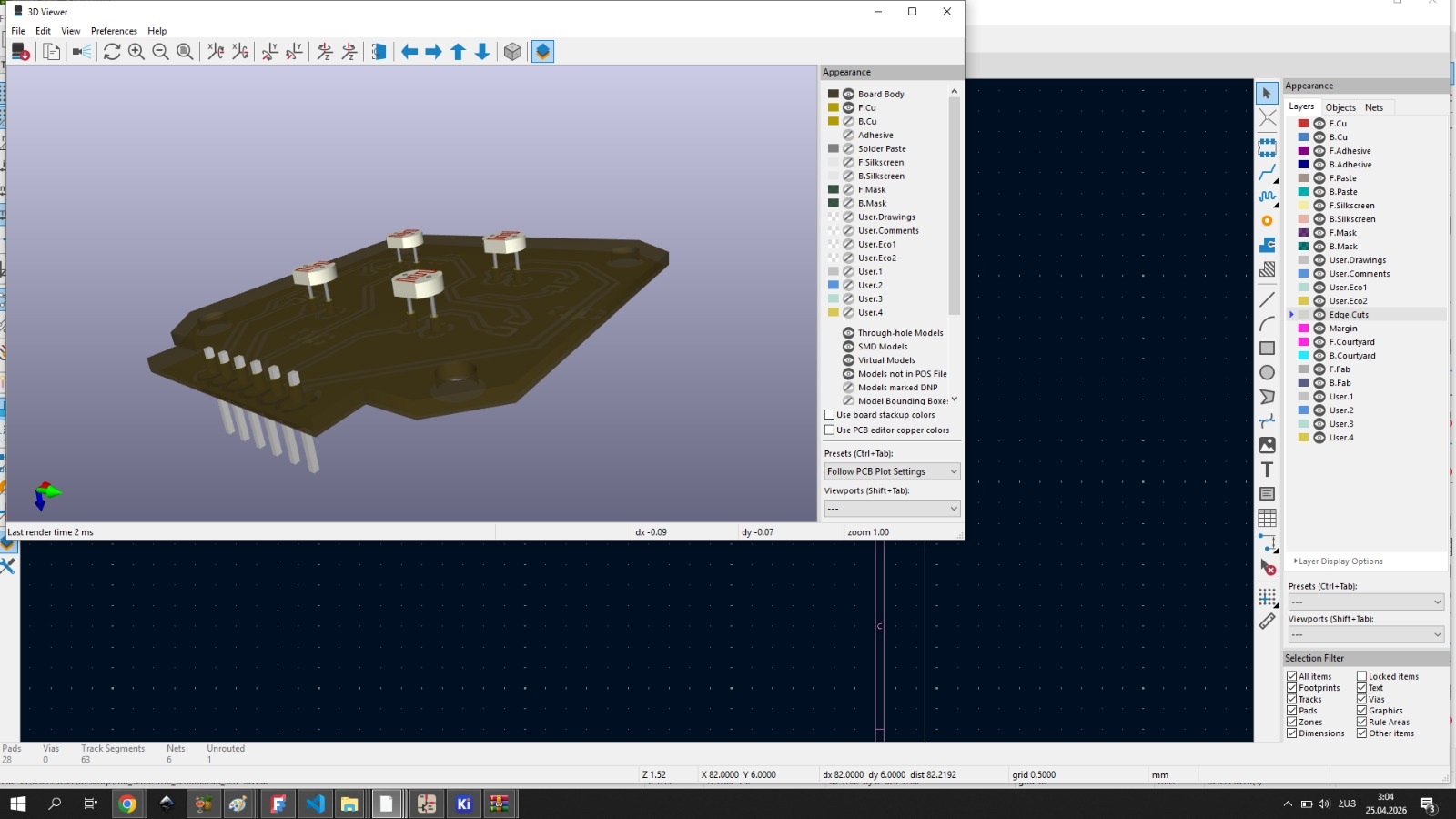
I already had the 3D model of my PCB from KiCad.
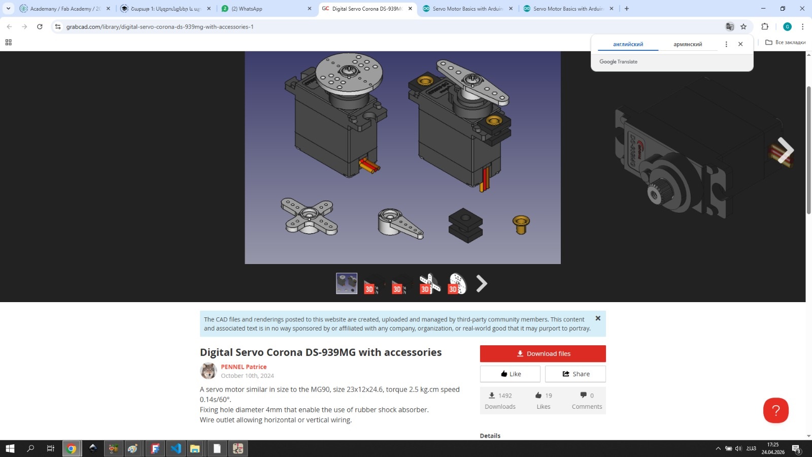
I also downloaded the 3D model of the servo motor from the internet.
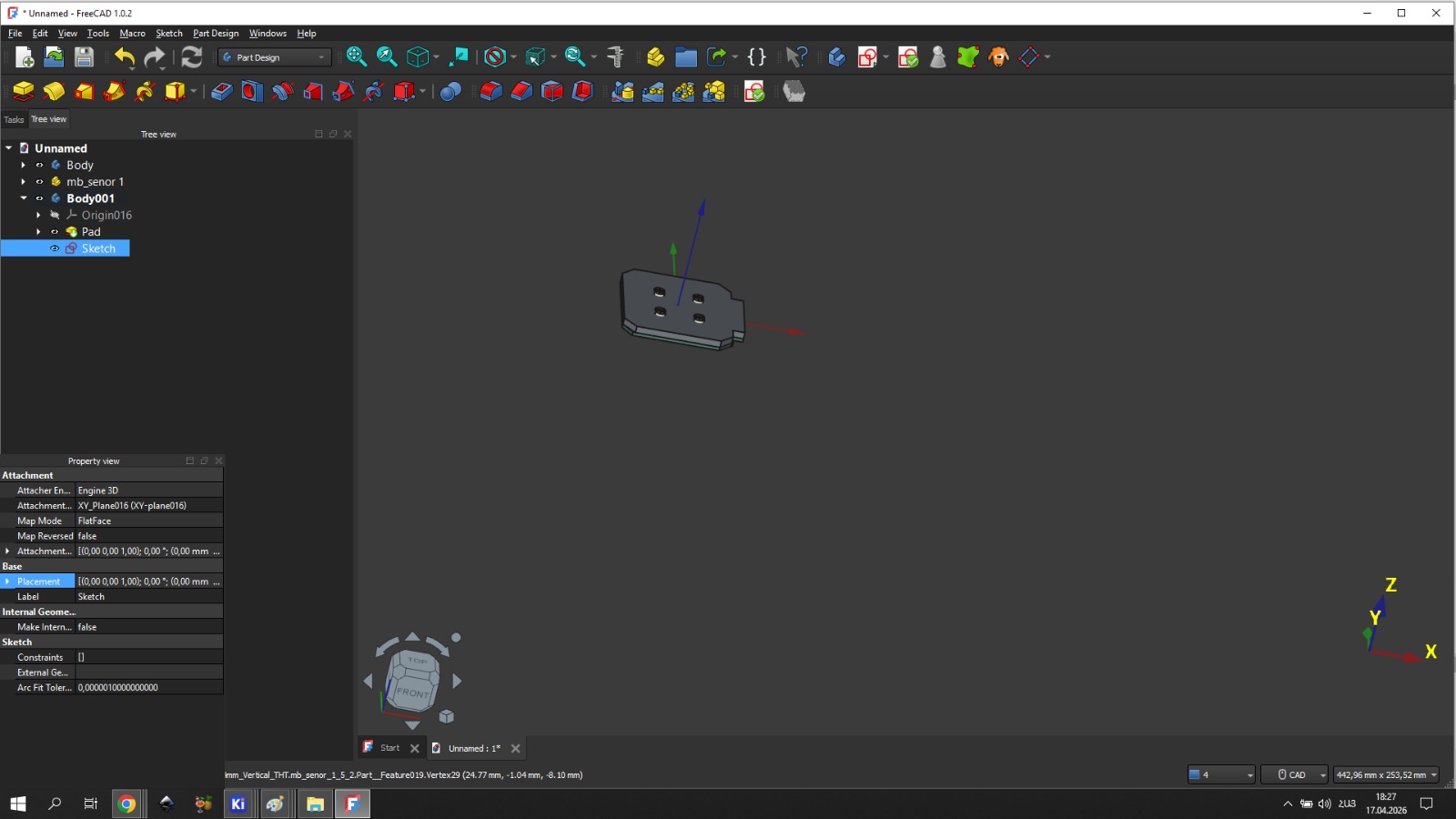
The KiCad 3D file served as the basis for starting the 3D modeling. I had to not only precisely indicate the locations of the passive sensors, but also the mounting points of the board. At the very top, there had to be a separating wall for those four passive sensors, with a height of 15 mm.
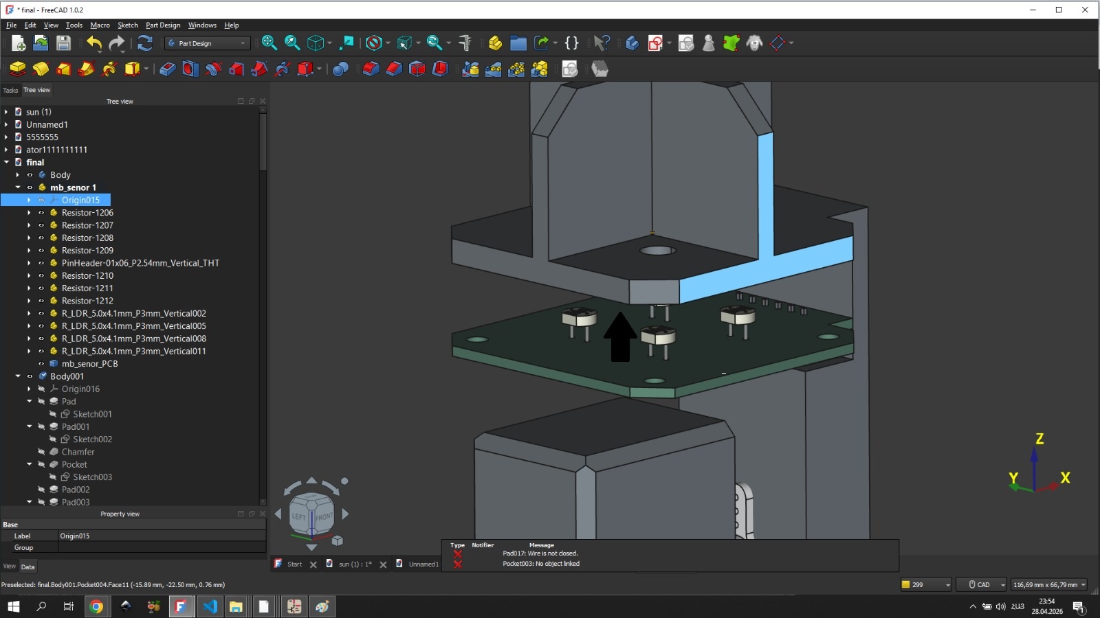
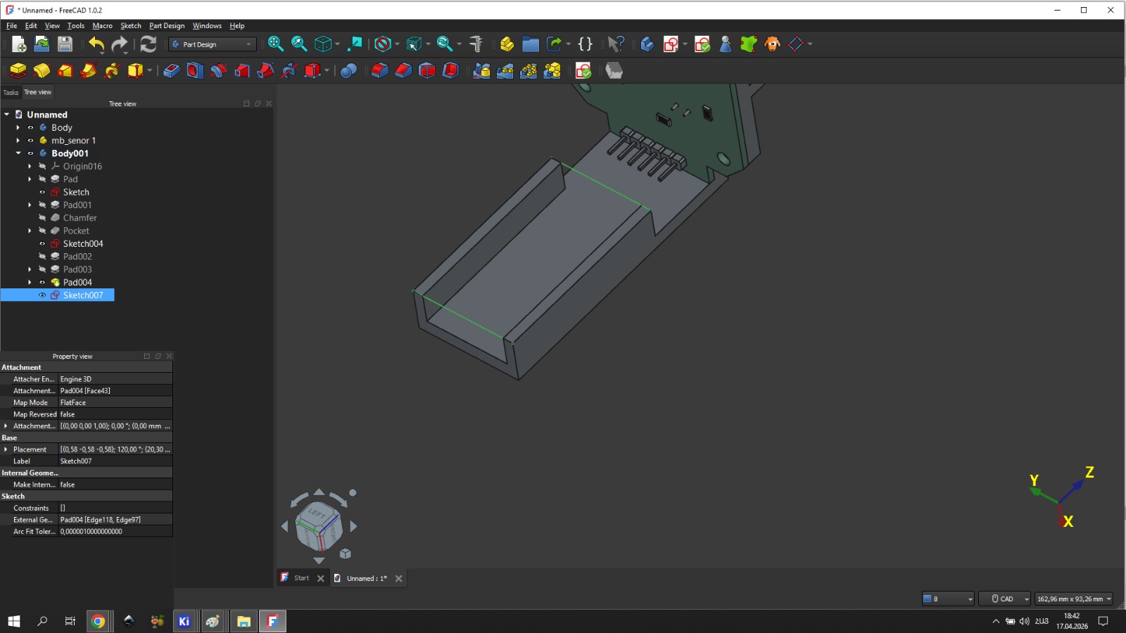
The passive sensors are mounted opposite to the board. The board must be positioned at the bottom of the body so that the passive sensors, passing through the holes, can absorb the sun’s rays.
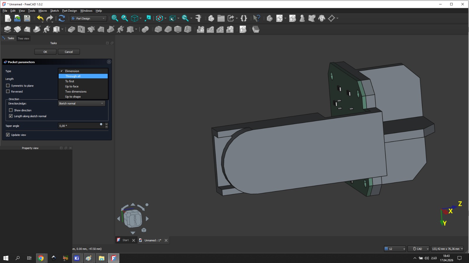
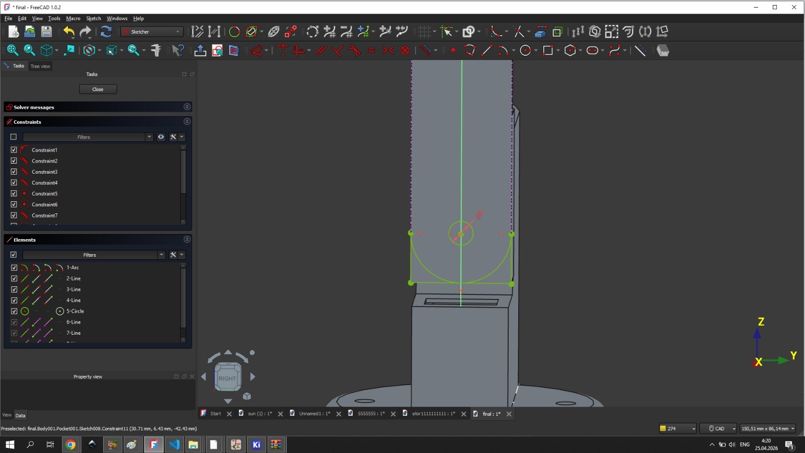
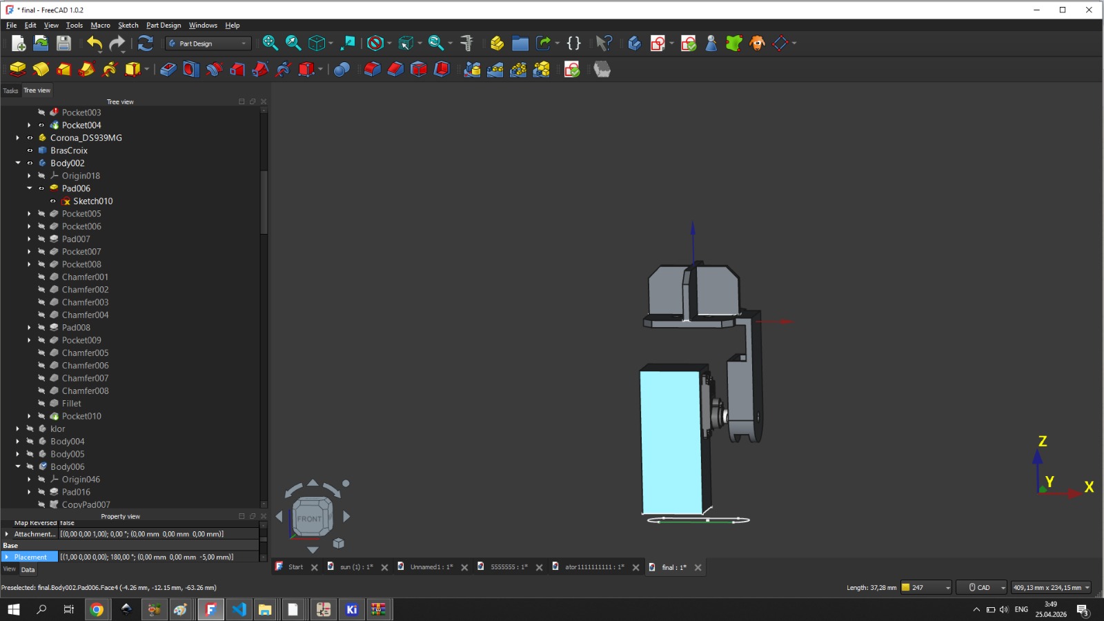
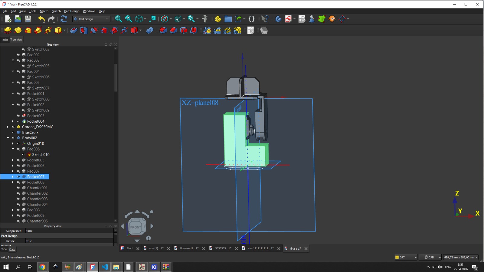
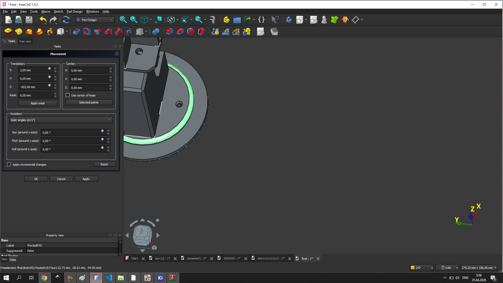
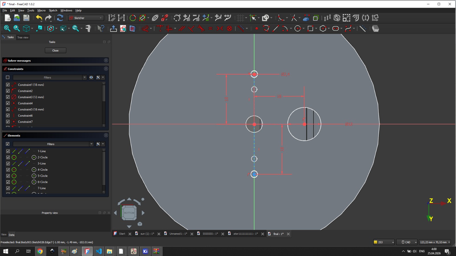
For this reason, a rectangular tube-shaped body was extended from the upper part. Since the lower part could come into contact with other parts of the mechanism, I decided to make it semicircular. The radius of the circle was 13 mm, and at its center I created a double-sided circular hole with a radius of 3 mm.
3D printing
After finishing the 3D model, I started 3D printing using PETG filament. I set the infill to 90%.
Assembly
Top section assembly
On my vertical working part, I attached the touchpad in place, then inserted the photoresistors through the corresponding holes from the opposite side and soldered them.
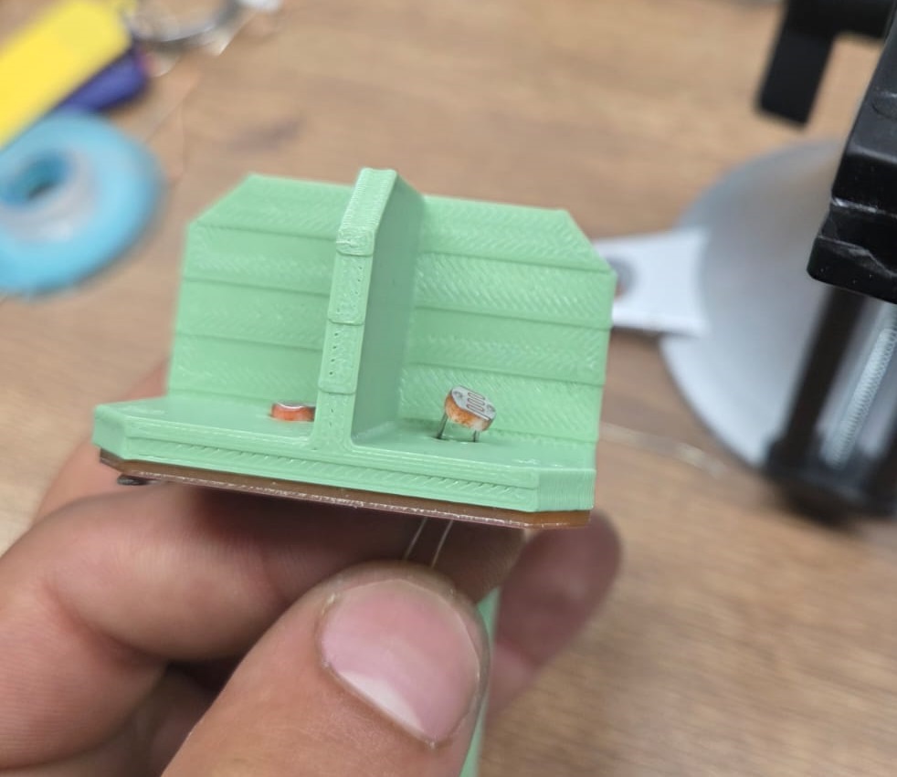
After soldering, I cut off the extra wires.
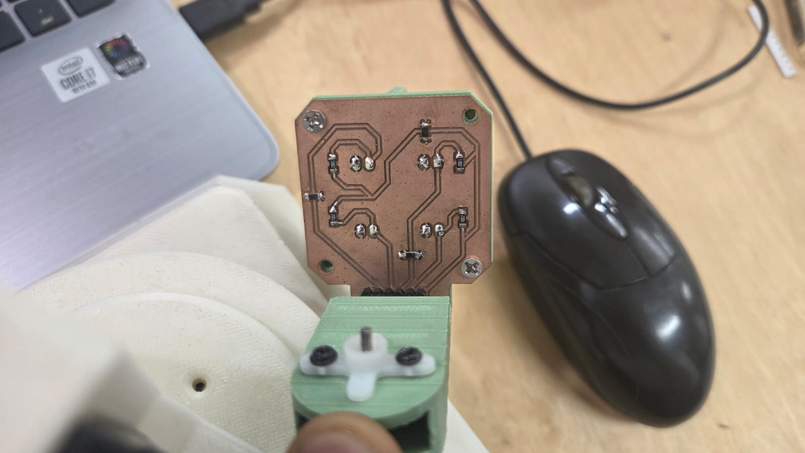
After that, I screwed in the part that holds the servo motor.
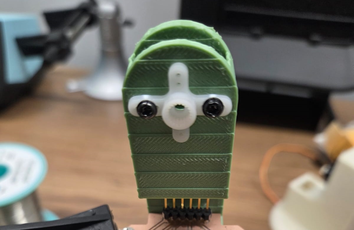
Then I attached the servo motor to my other designed part.
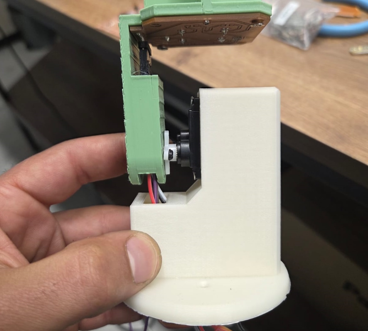
After connecting the wires, I joined my two parts together.
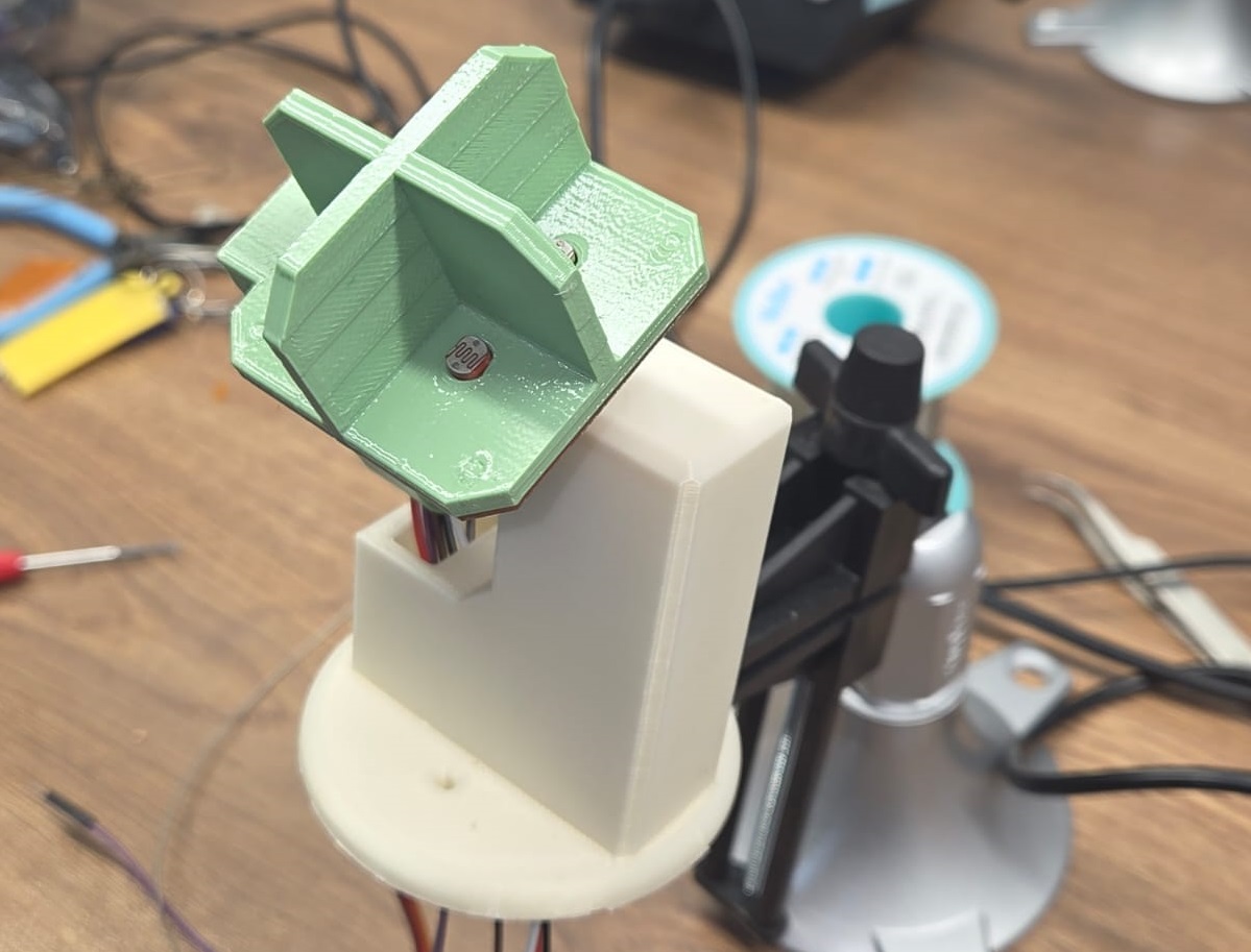
Bottom section assembly
Ani took charge of assembling the bottom section, since she designed and printed the 3D models for the bottom section. Details can be found on Ani’s page.
Joining together
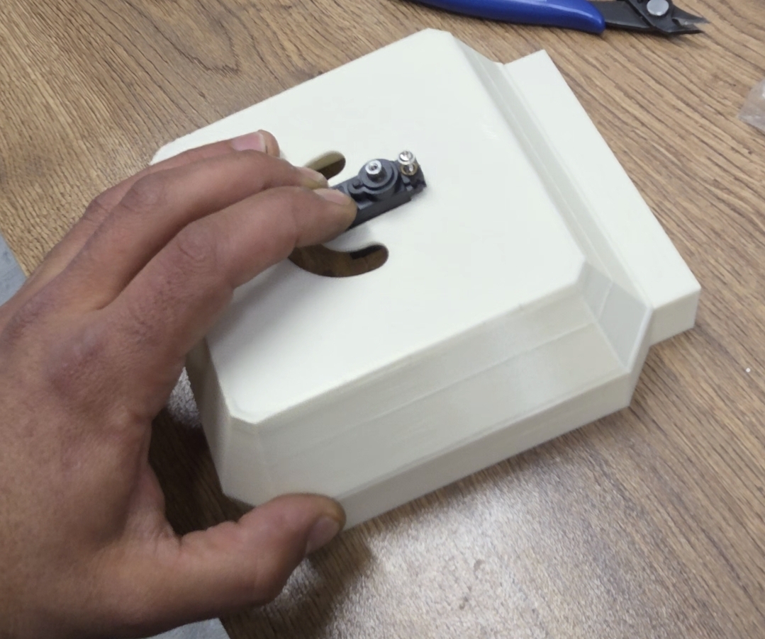
The part that would join my model and Ani’s designed model together was circular. On my side there were two mounting holes and one hole through which the wires would pass. I passed those wires through that hole and screwed the circular connecting part on with screws.
Coding
All the code in this section was written entirely by us as a team, through hands-on experimentation and group problem solving. No AI prompts were used.
After assembly, we moved to programming. With both servos at 0°, we named the four photoresistor pins:
#define topLeft  A1
#define topRight A0
#define bottomLeft A3
#define bottomRight A2
We read the sensor values and printed them to the Serial Monitor once per second to confirm the wiring was correct, checking each sensor by covering it with a finger.
The layout mapping which sensor pairs control which servo:
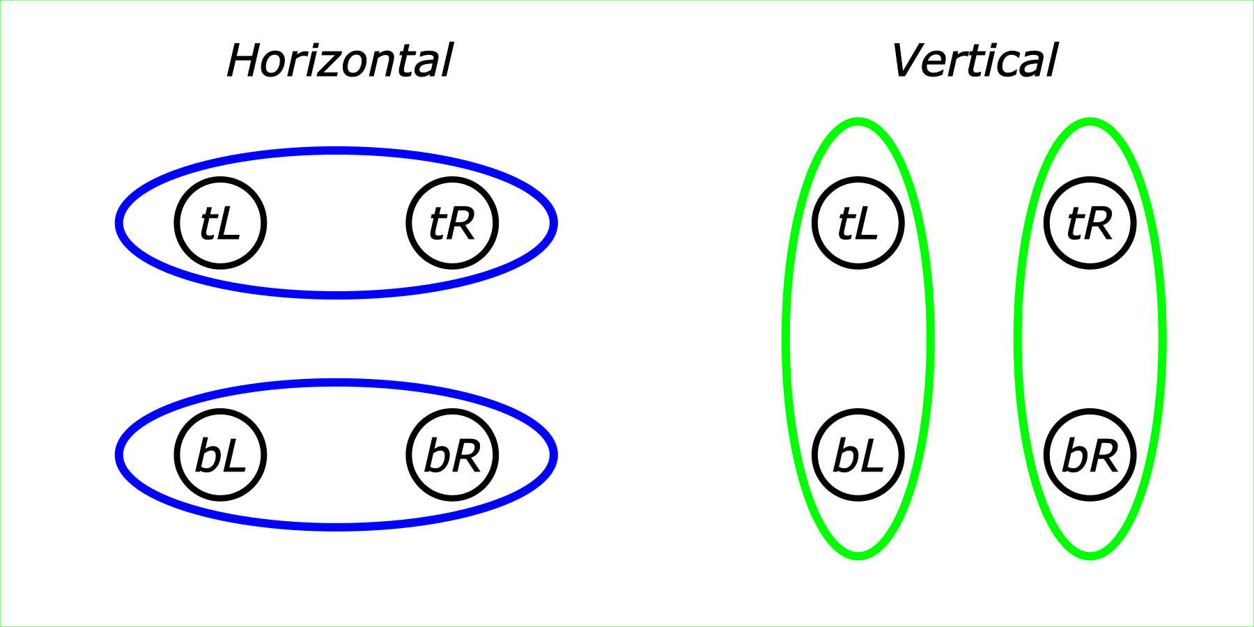
We started with the horizontal servo only. We imported the Servo library, created a servo object, and attached it to pin 8 with a starting position of 90°.
We tested this with a flashlight indoors.
Two problems came up. First, nothing stopped the position from going past the servo’s 0–180° range, so we added boundary checks. Second, when both sensor readings were close, the code kept rotating back and forth — so we added a percentage-difference threshold that the readings must exceed before the servo moves at all.
Once both fixes were in place, the device worked correctly.
Rather than duplicating this logic for the vertical servo, we refactored it into a single function, sensdetect(), that handles both axes the same way.
The final code:
#include <Servo.h>

#define topLeft  A1
#define topRight A0
#define bottomLeft A3
#define bottomRight A2

int horizontalpos = 90;
int verticalpos = 90;
int threshold = 5;

Servo horizontalservo;
Servo verticalservo;

void setup() {
  Serial.begin(9600);
  pinMode(topLeft, INPUT);
  pinMode(topRight, INPUT);
  pinMode(bottomLeft, INPUT);
  pinMode(bottomRight, INPUT);
  horizontalservo.attach(8);
  verticalservo.attach(10);

  horizontalservo.write(horizontalpos);
  delay(500);

  verticalservo.write(verticalpos);
  delay(500);
}

void loop() {
  int tL = analogRead(topLeft);
  int tR = analogRead(topRight);
  int bL = analogRead(bottomLeft);
  int bR = analogRead(bottomRight);

  sensdetect(tL, tR, horizontalservo, horizontalpos);
  sensdetect(bL, tL, verticalservo, verticalpos);
}

void sensdetect(int start, int finish, Servo &s, int &position ) {
  if(start < finish && position > 0 && (finish - start)*100/finish > threshold) {
    position = position - 1;
    s.write(position);
    delay(25);
    Serial.print("position:");
    Serial.println(position);
  }
  if(finish < start && position < 180 && (start - finish)*100/start > threshold) {
    position = position + 1;
    s.write(position);
    delay(25);
    Serial.print("position:");
    Serial.println(position);
  }
}
This setup let the device track light from all four directions and rotate both servos to follow it, without oscillating once it settled near the source.