Assignment 3: Computer controlled cutting
This assignment is about documenting my experience with Computer-Controlled Cutting, particularly laser cutting. It covers how I designed my project, the challenges and mistakes I faced, and how I utilized laser cutting to create my design. I will also explain the safety measures I followed throughout the process.
Laser cutting is a technology that uses a laser to vaporize materials, resulting in a cut edge. While typically used for industrial manufacturing applications, it is now used by schools, small businesses, architecture, and hobbyists. Laser cutting works by directing the output of a high-power laser most commonly through optics. The laser optics and CNC (computer numerical control) are used to direct the laser beam to the material. A commercial laser for cutting materials uses a motion control system to follow a CNC or G-code of the pattern to be cut onto the material. The focused laser beam is directed at the material, which then either melts, burns, vaporizes away, or is blown away by a jet of gas,[1] leaving an edge with a high-quality surface finish.
Click here to read more.
A vinyl cutter is an entry-level machine for making signs. Computer-designed vector files with patterns and letters are directly cut on the roll of vinyl which is mounted and fed into the vinyl cutter through USB or serial cable. Vinyl cutters are mainly used to make signs, banners and advertisements. Advertisements seen on automobiles and vans are often made with vinyl cut letters. While these machines were designed for cutting vinyl, they can also cut through computer and specialty papers, as well as thicker items like thin sheets of magnet.
Click here to read more.
Highlight Moments of the Week
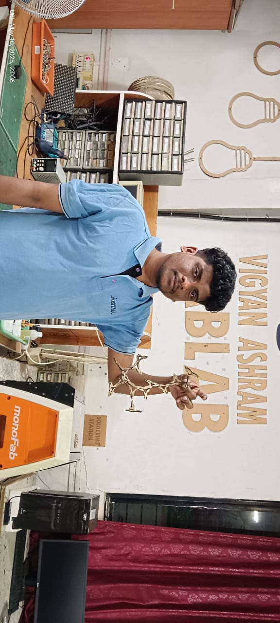
I am showing the final results below
Group Assignment
Objective of the Group Assignment:
- do your lab's safety training
- characterize your lasercutter's focus, power, speed, rate,
- kerf, joint clearance and types
Individual Assignment
Objective of the Individual Assignment:
- cut something on the vinylcutter
- design, lasercut, and document a parametric construction kit,
- accounting for the lasercutter kerf,
- which can be assembled in multiple ways,
Basics of Laser cutting:
What is Laser: A laser is a device that emits light through a process of optical amplification based on the stimulated emission of electromagnetic radiation. The word laser originated as an acronym for light amplification by stimulated emission of radiation.[1][2] The first laser was built in 1960 by Theodore Maiman at Hughes Research Laboratories, based on theoretical work by Charles H. Townes and Arthur Leonard Schawlow and the optical amplifier patented by Gordon Gould.
Click here to read more.
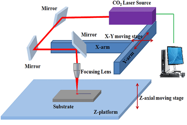
What is CO2 Laser: The carbon-dioxide laser (CO2 laser) was one of the earliest gas lasers to be developed. It was invented by Kumar Patel of Bell Labs in 1964[1] and is still one of the most useful types of laser. Carbon-dioxide lasers are the highest-power continuous-wave lasers that are currently available. They are also quite efficient: the ratio of output power to pump power can be as large as 20%. The CO2 laser produces a beam of infrared light with the principal wavelength bands centering on 9.6 and 10.6 micrometers (μm).
Click here to read more.
What is Laser cutting: Laser cutting is a precise and efficient process that uses a focused laser beam to cut or engrave materials. The laser generates intense heat that melts or vaporizes the material along a defined path. It is commonly used for cutting wood, acrylic, fabric, cardboard, and some metals. Designs are created using 2D vector software and then sent to the laser machine for execution. Laser cutting is popular in industries, fabrication labs, and hobby projects due to its accuracy and clean finish.
What is Kerf in laser cutting:Kerf in laser cutting refers to the width of material that the laser removes during the cutting process. It is caused by the thickness of the laser beam and the heat-affected zone. The kerf can vary depending on the material type, laser power, and cutting speed. Designers must account for the kerf when creating precise parts to ensure proper fitting. Ignoring kerf may lead to gaps or tight fits in assembled pieces.
Schematic of a Laser cutting and Kerf
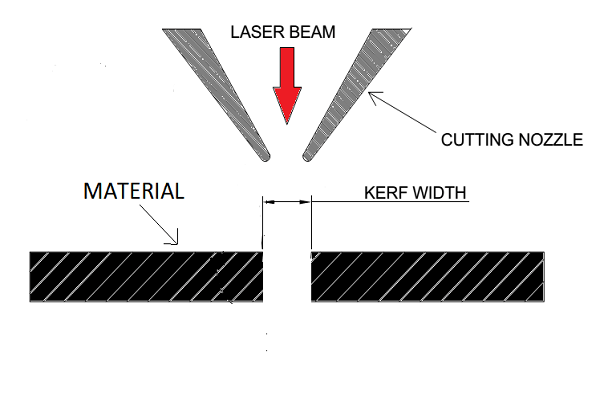
Source: Reference
Parametric Designing:
Parametric designing is a method where design elements are controlled by parameters such as dimensions, angles, or formulas. Instead of fixed shapes, the design adapts automatically when a parameter changes. This allows for easy customization, scalability, and rapid modifications. It is commonly used in CAD software for architecture, product design, and digital fabrication. Parametric design helps save time and ensures accuracy, especially in projects with repeated or variable components.
Parametric designing in SolidWorks :
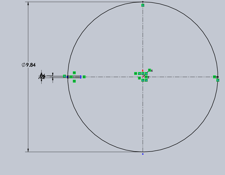
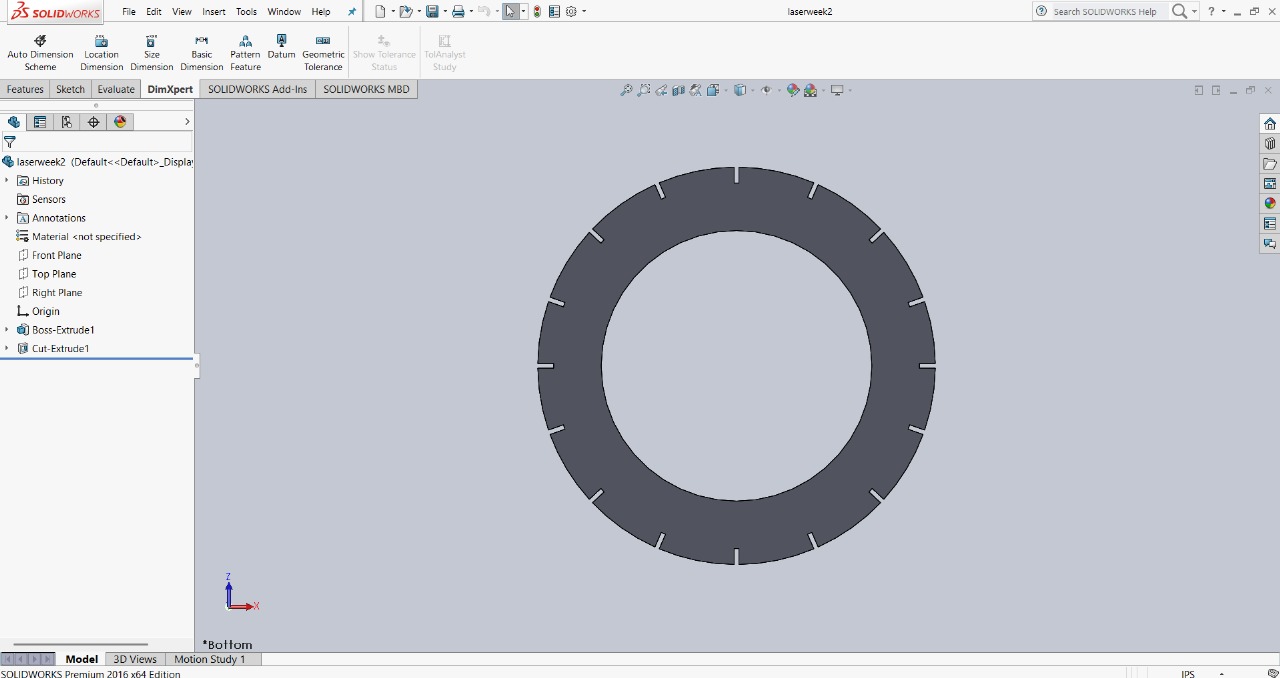
First step: For my parametric design assignment, I decided to design something unique. To begin, I started by creating a circle and then proceeded to add slots on it in a circular pattern. This step was the foundation, and I’m planning to expand and refine the design further as I go.
|
|
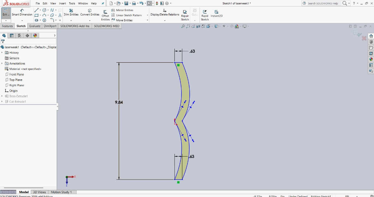
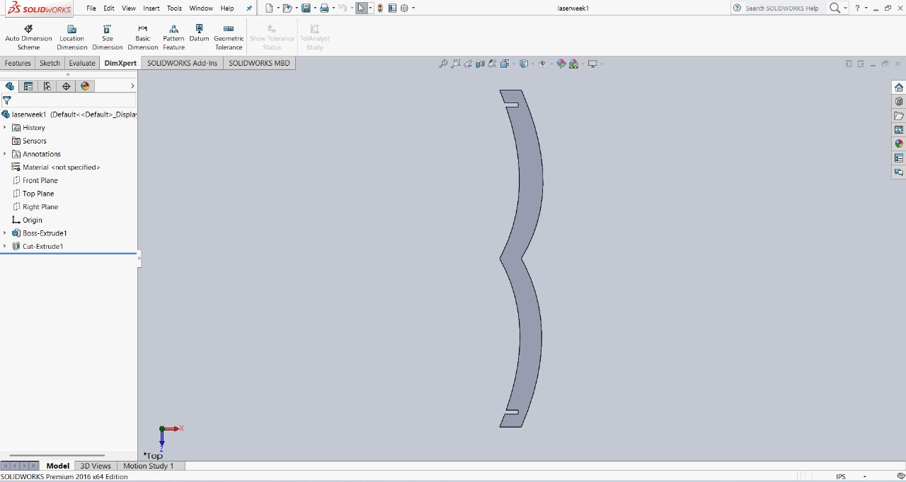
Next step: The next step in my design process involved fixing the slots. To do this, I created a conducting joint line, which allowed me to assemble two circles. I will show the images below to illustrate this step more clearly.
|
|
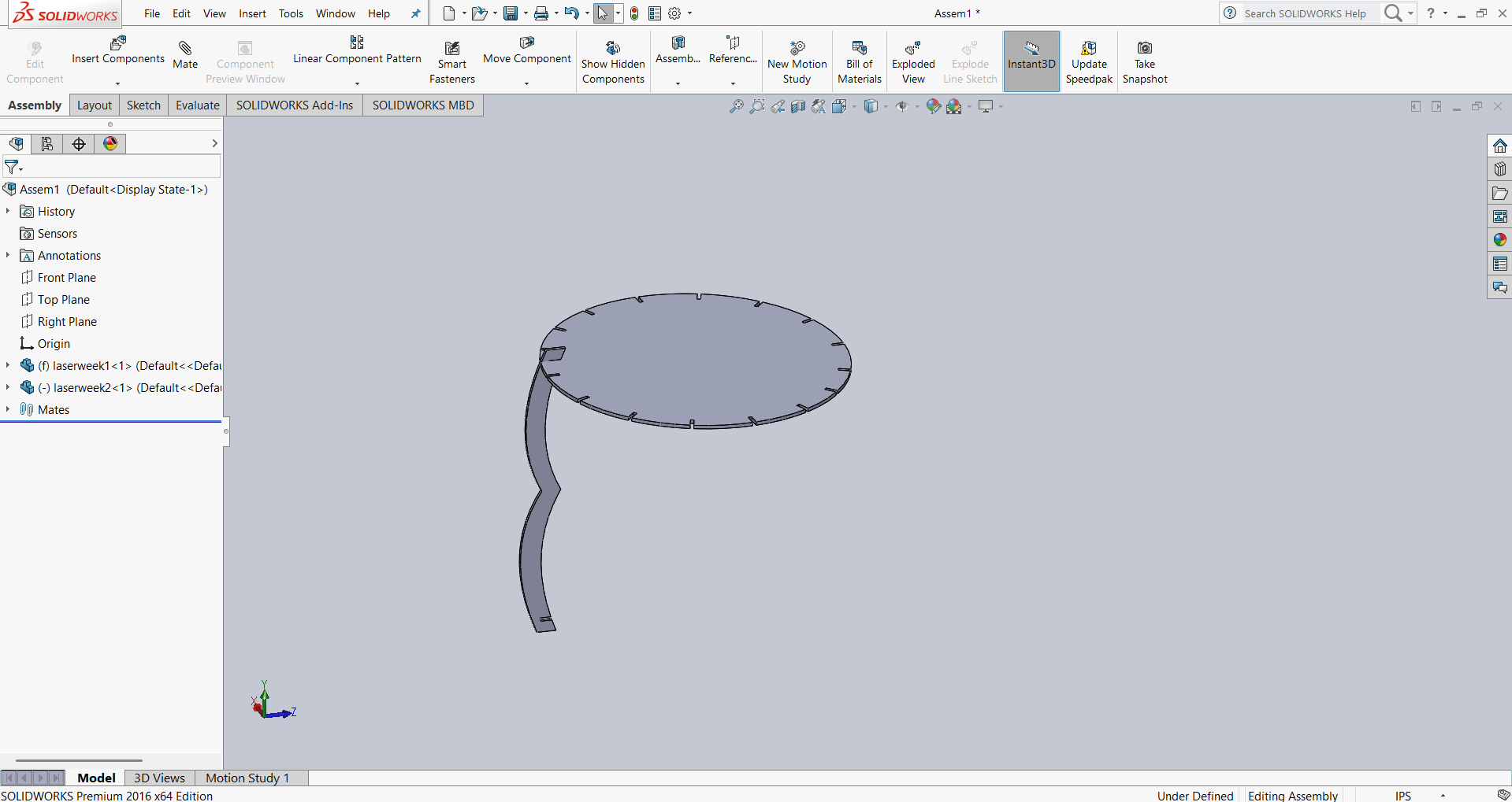
After creating the two parts, I began the assembly process to check the fit and functionality. I carefully aligned the components to ensure they were properly connected. The assembly was done step by step, and I verified that everything fit together as intended. Below, I’m showing how I assembled my design for
|
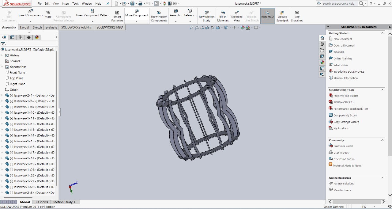
|
After completing the assembly, I saved my files in DXF format. This format is suitable for further processing like laser cutting or CNC machining.
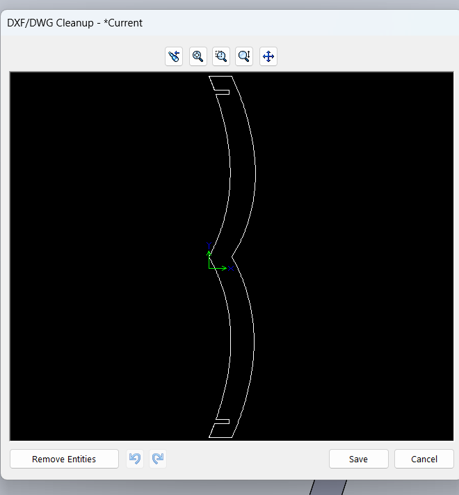
|
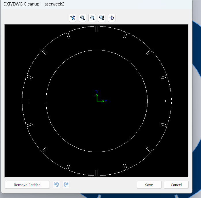
|
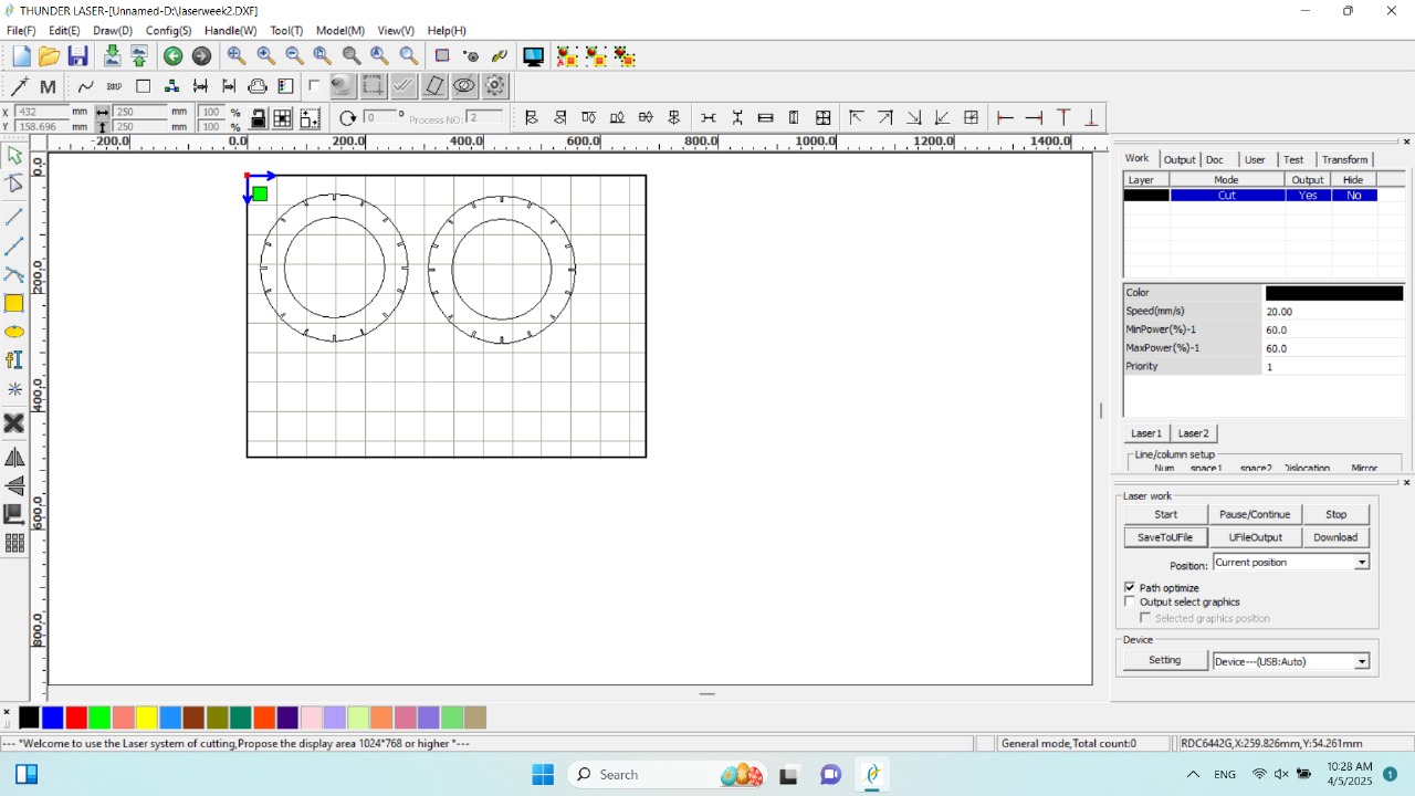
Next, I used RDWorks software to transfer my design to the laser cutting machine. The software reads the DXF file and converts it into a format compatible with the machine. Before cutting, I measured the length and width of the cardboard sheet and verified that it matched the dimensions of my design frame.
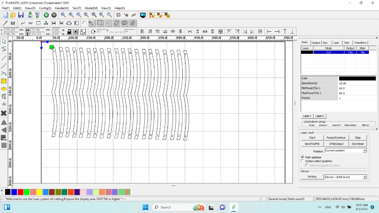
|
|
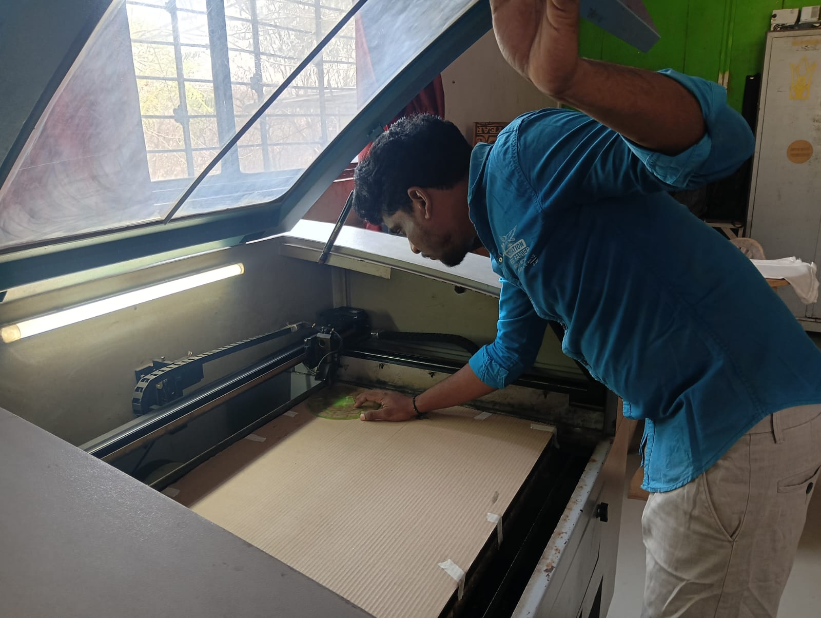
I adjusted the spacing between the cardboard and the laser beam to ensure proper focus. I used cardboard as the material for cutting my design.
|
|
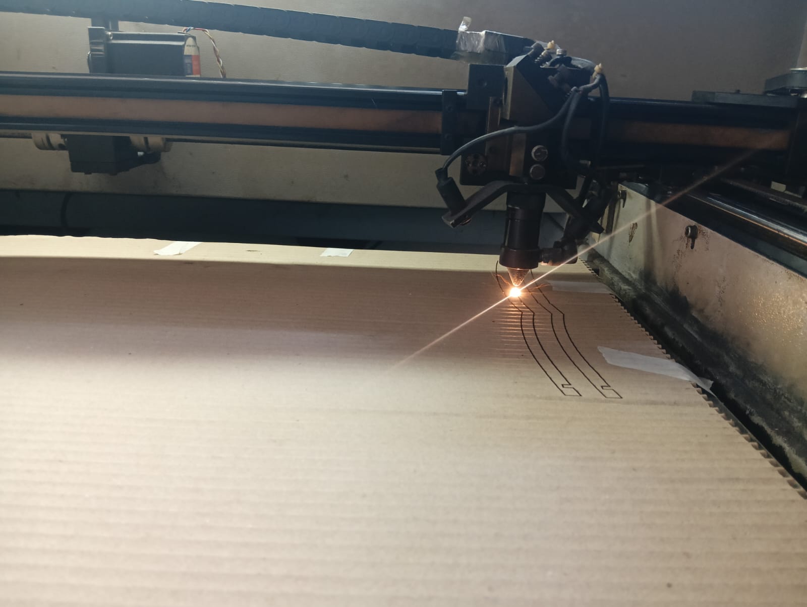
After arranging everything correctly, I started cutting my design by turning on the laser. The setup was aligned to ensure precise and accurate cutting.
|
|
After cutting all the parts, I carefully removed them from the cardboard sheet. I then began the assembly process, which is shown in the image below.
|
|
I started the assembly process by fitting all the cut parts together. After completing the assembly, the final structure of my output clock was ready. The image below shows how my completed clock looks.
|

|
Parametric Design with Multiple Assembly Options:
To understand laser cutting and parametric design, I first created a basic model. This helped me learn how parameters affect the design and how laser cutting works in practice.
After gaining a better understanding, I redesigned the model with the goal of allowing it to be assembled in multiple ways.
Below, I have documented the steps I followed to create this improved, flexible design.
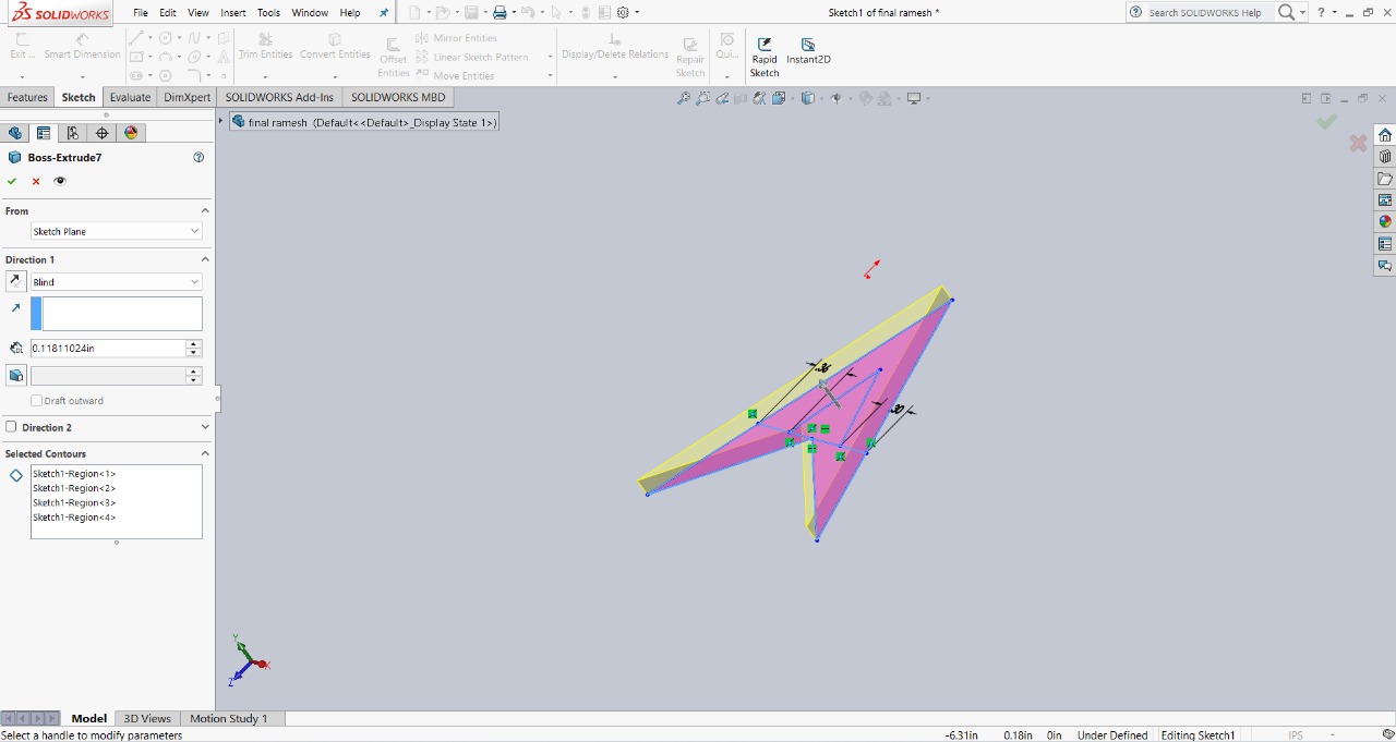
Step 1 : I started designing in SolidWorks. First, I created a triangle in a unique way and extruded it to a thickness of 3mm.The image below shows this initial design.
|
|
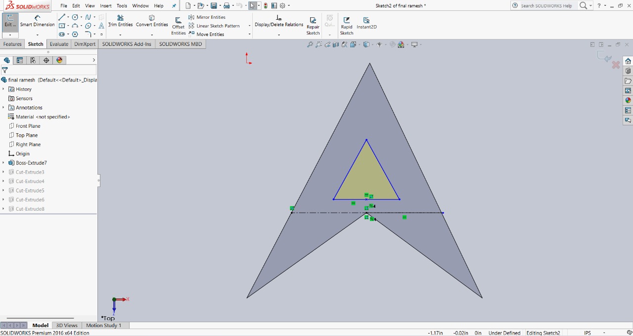
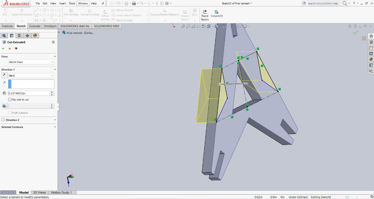
Step 2 : I then created a smaller triangle inside the larger triangle. Using the extruded cut feature, I removed the inner shape to create a unique design. This step helped refine the overall look and structure of the model.
|
|
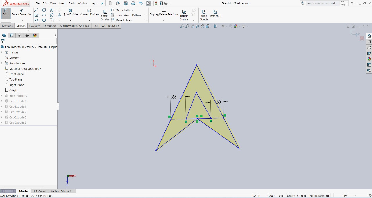
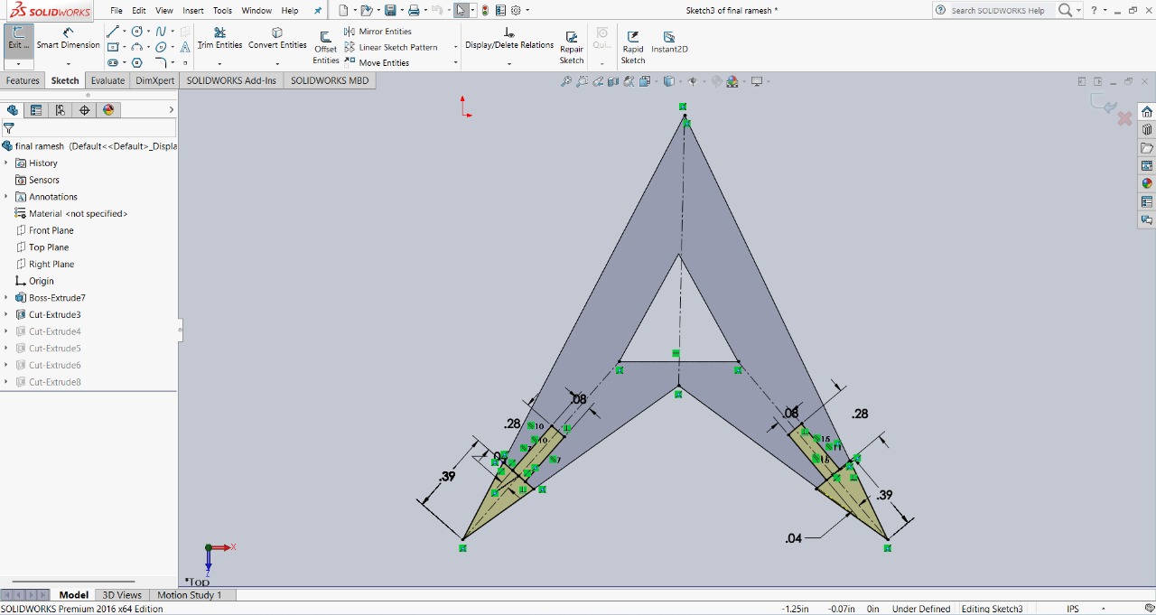
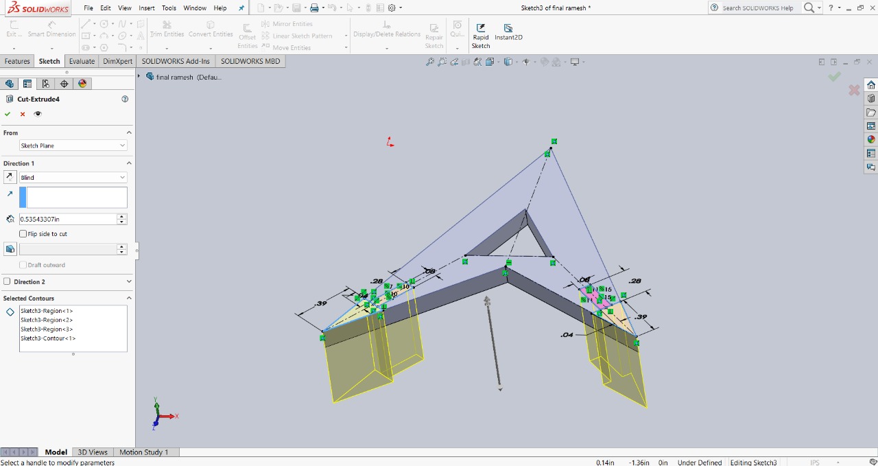
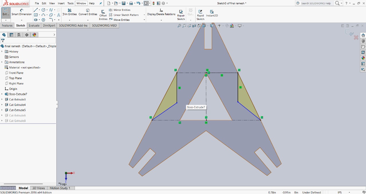
Step 3 : After that, I created slots at the corners of the triangle. These slots are designed to help assemble the parts in different ways. The image below shows the final result.
|
|
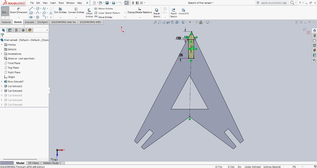
Step 4 : To provide more assembly options, I created a slot at the top of the triangle and cut it out. The slot size is 2mm in width and 5mm in depth. The image below shows this feature for better clarity.
|
|
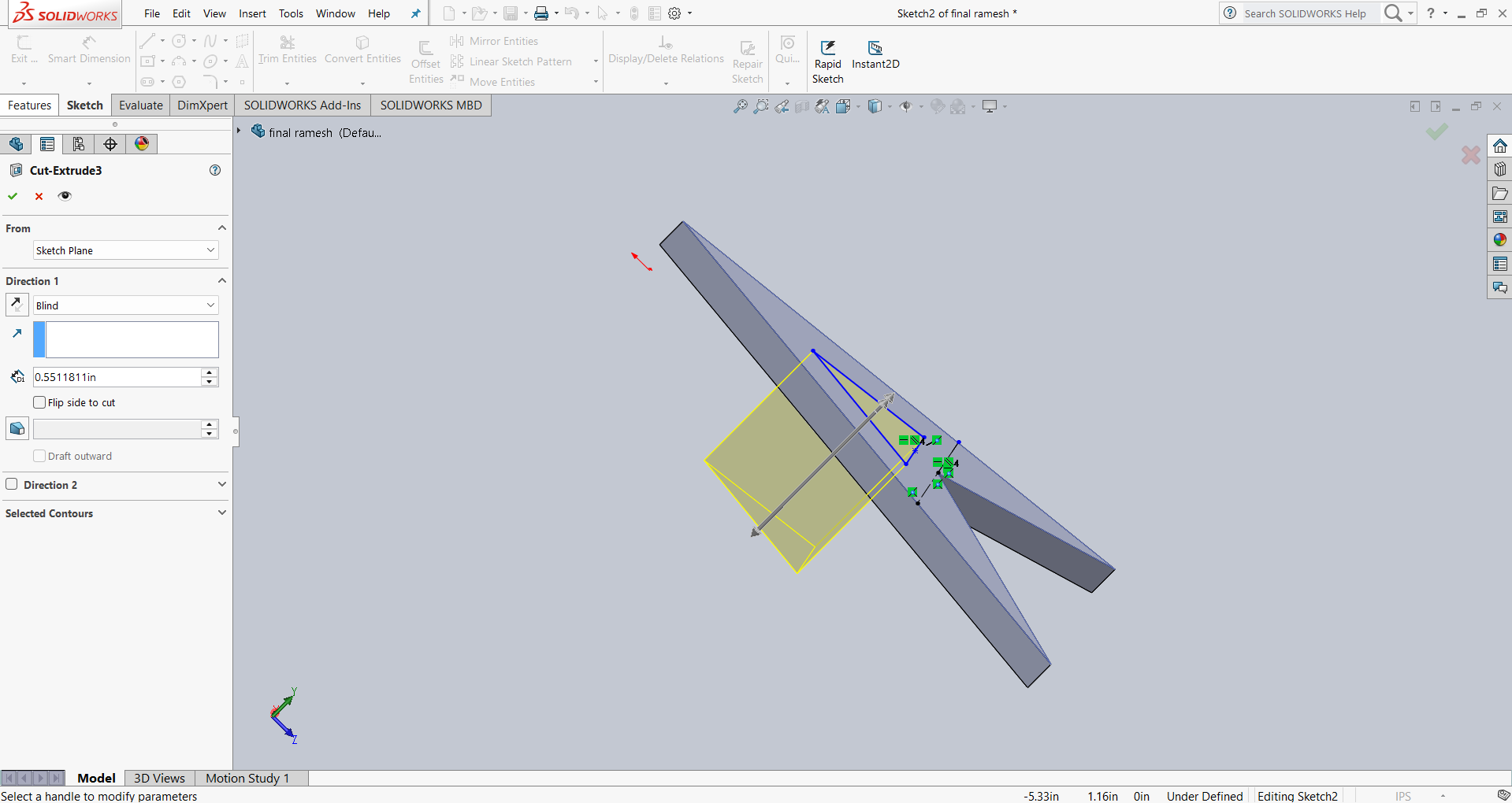
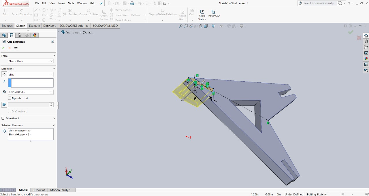
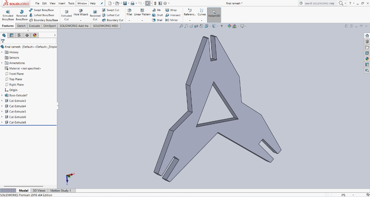
Step 5 : To make the design look more unique, I removed the sharp edges of the triangle. This not only improved the appearance but also added a distinct style to the model. I used the extruded cut option to remove those parts, and with that, my final design was ready.
|
|
This is the final design, showcasing all the features added for multiple assembly options and a unique appearance.
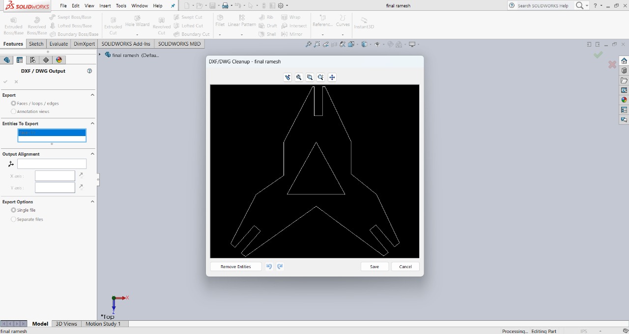
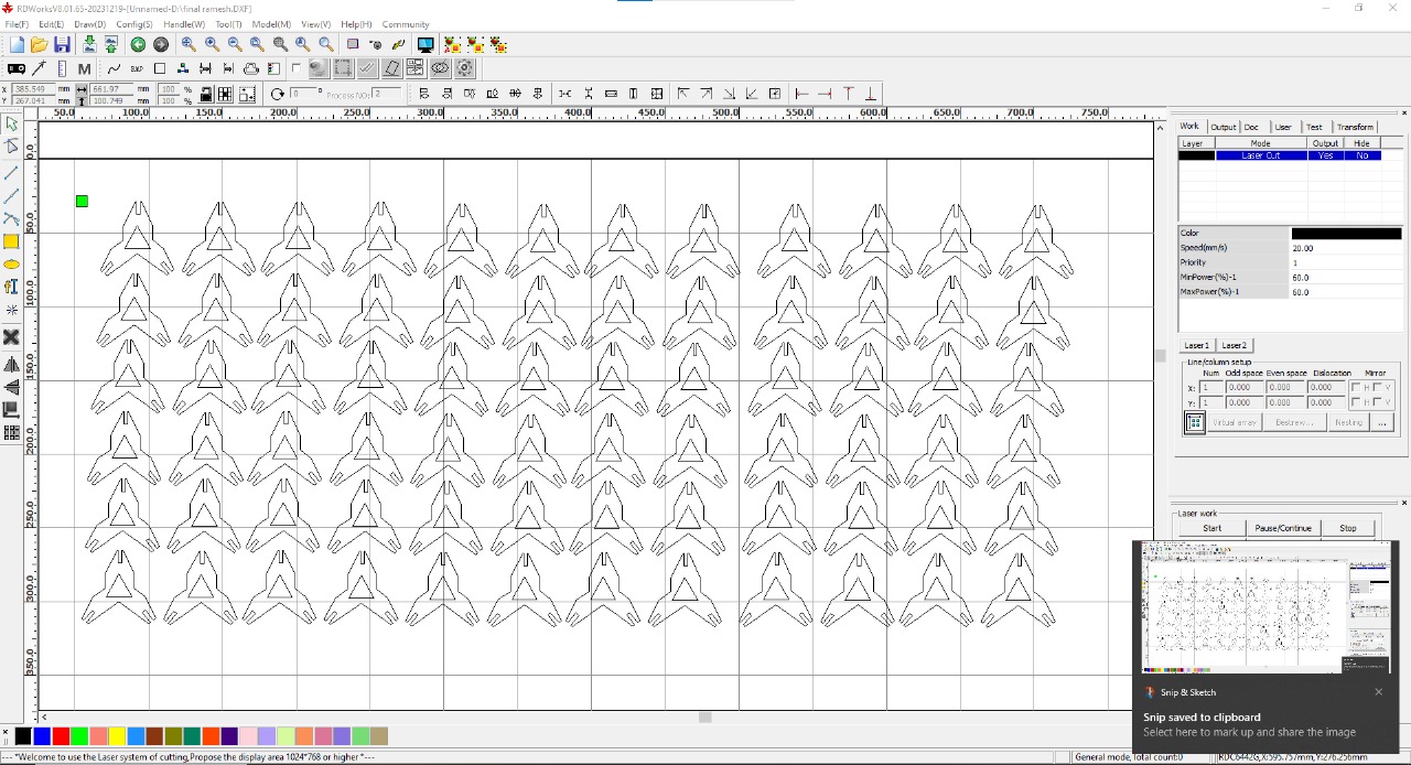
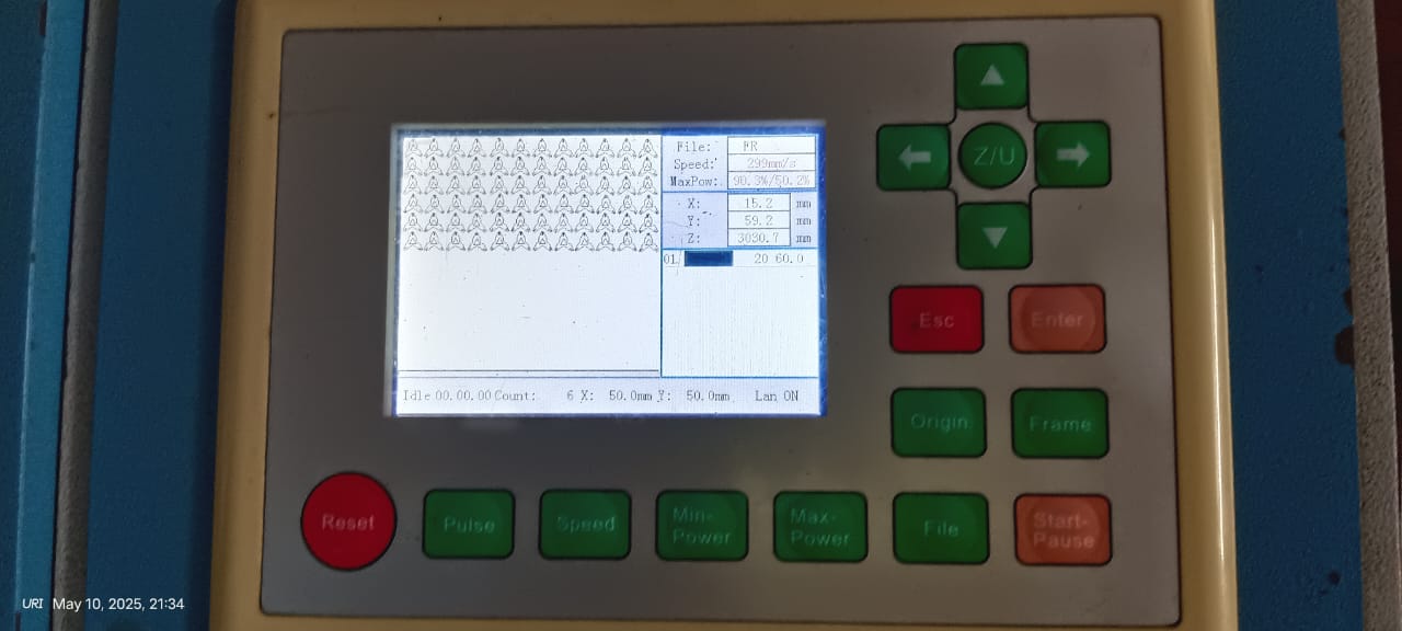
After completing my final design, I saved it in DXF format, which is a suitable file format for RDWorks. Then, I imported the design into RDWorks, arranged 72 pieces, and set the power to 60 and speed to 20. These settings were comfortable and worked well for cutting my design.
|
|
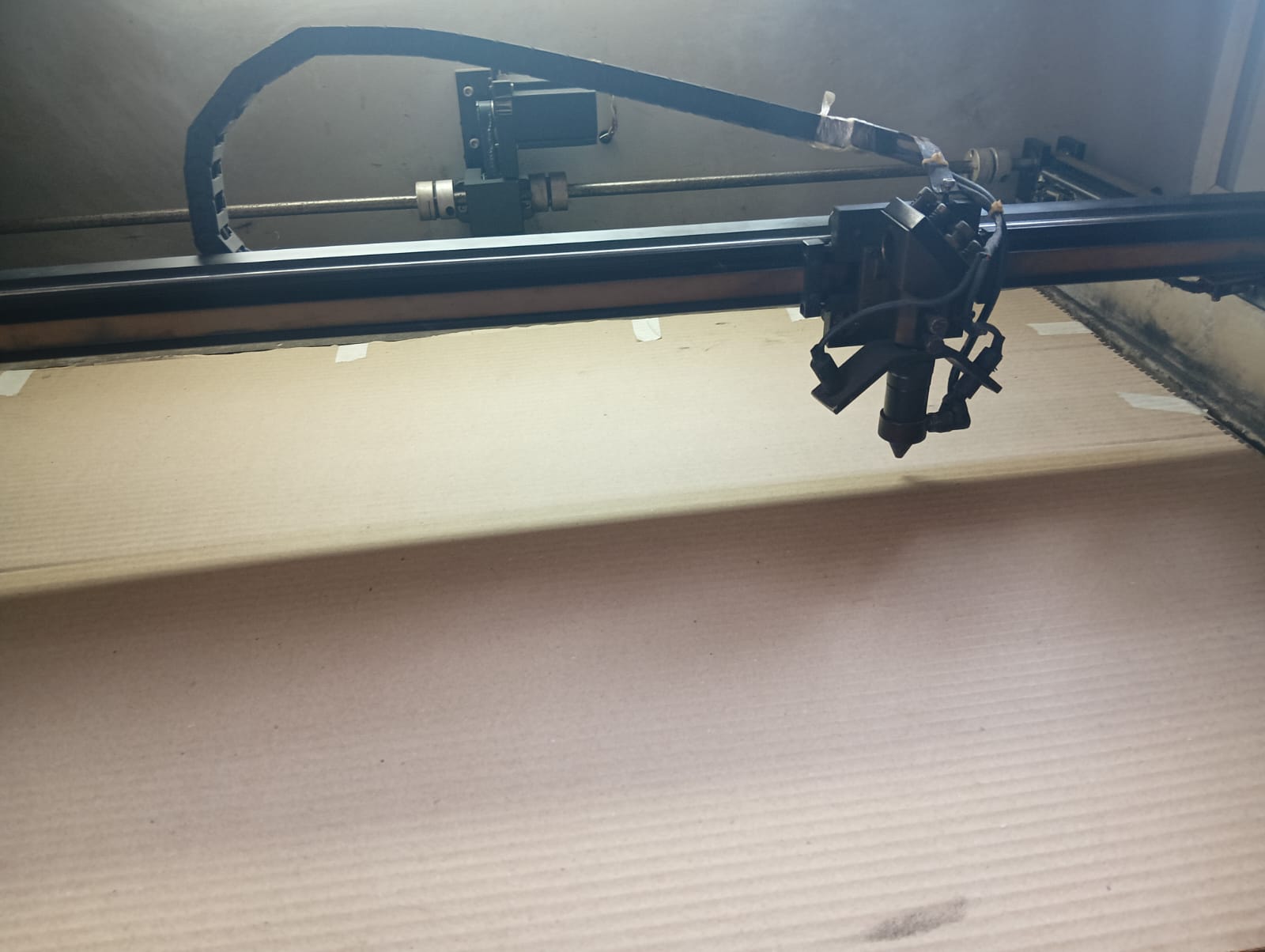
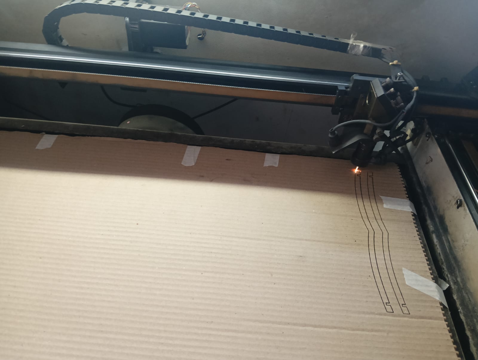
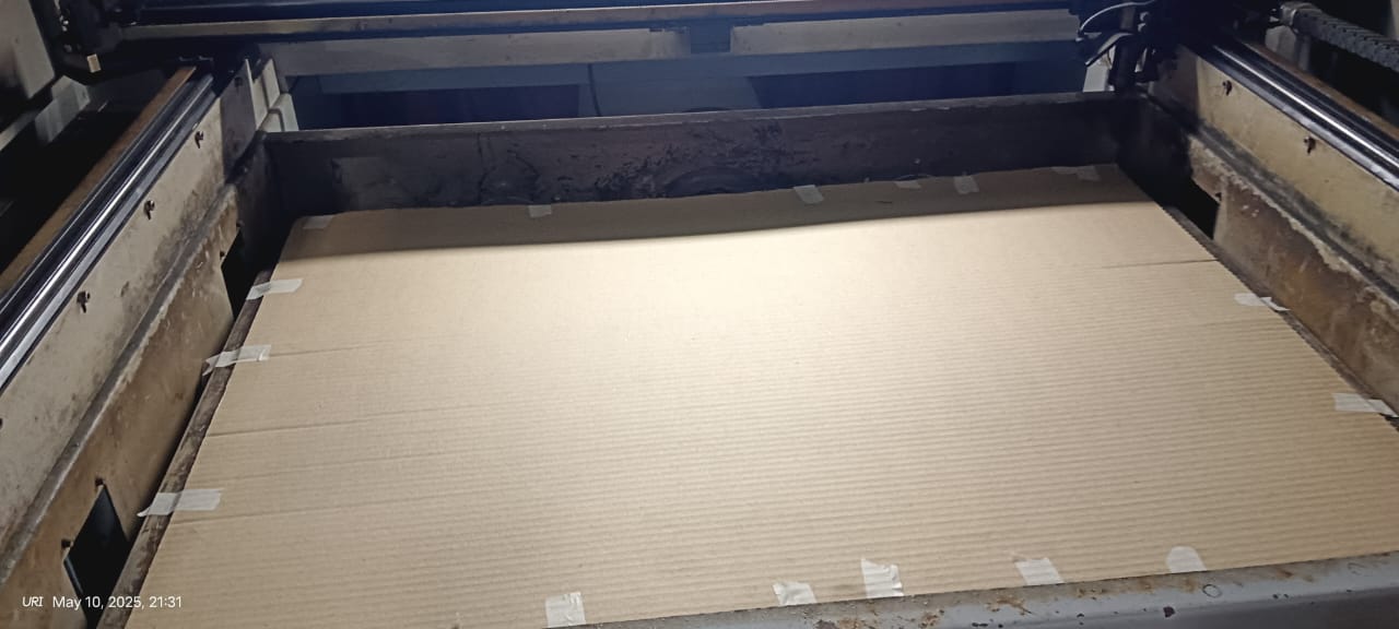
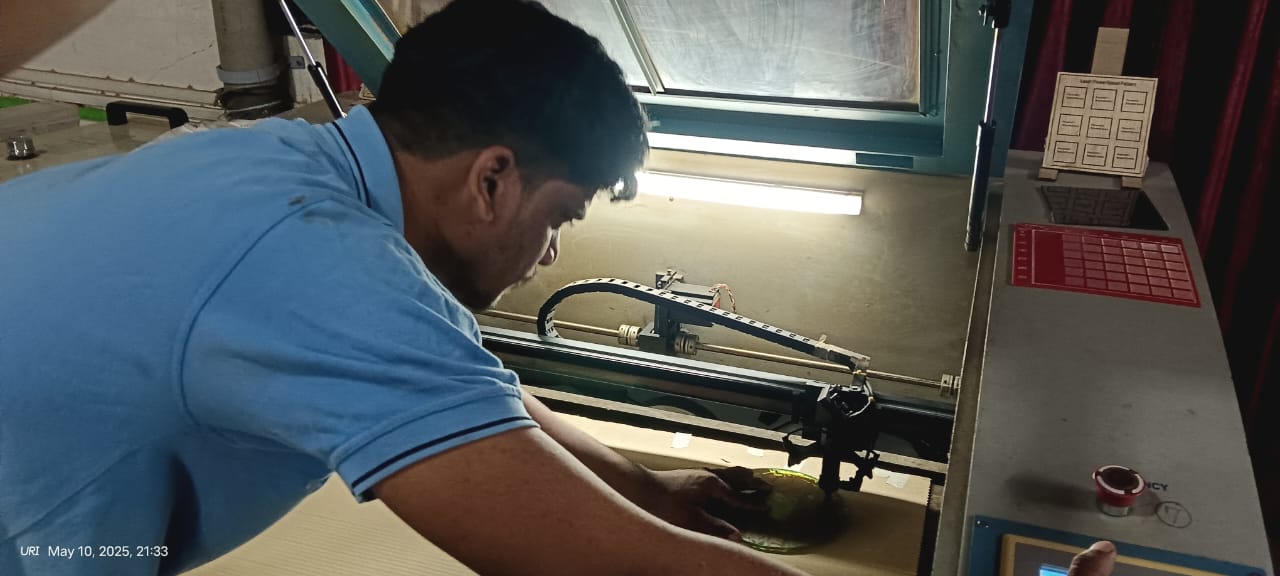
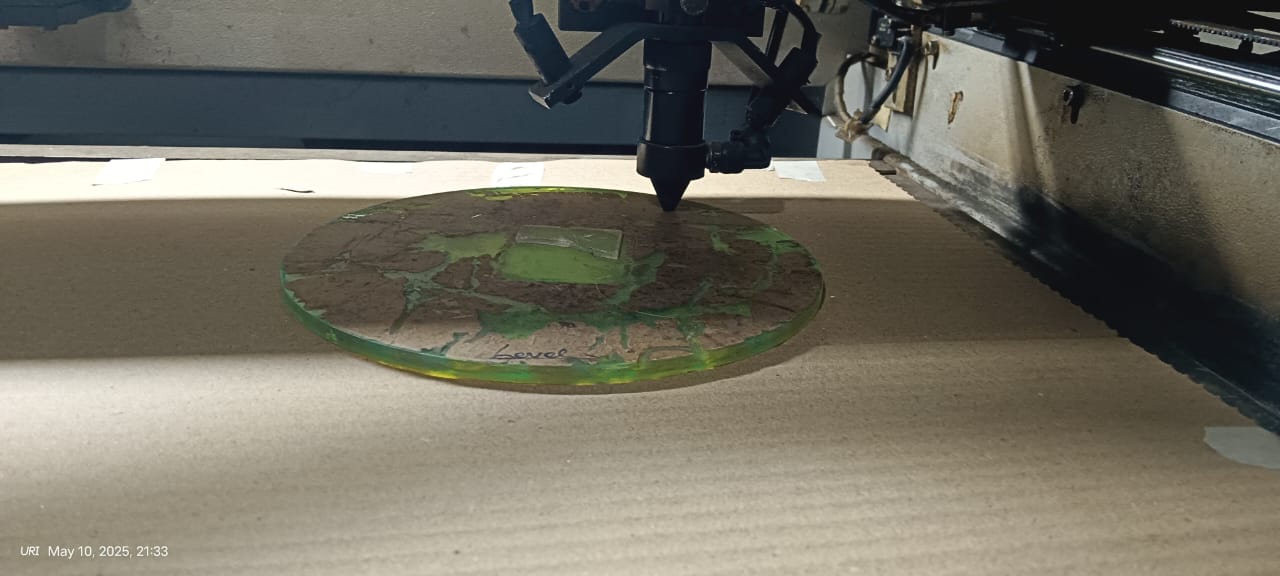
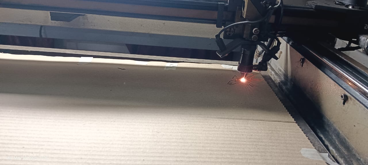
After that, I placed a new cardboard sheet on the laser cutting machine. I carefully adjusted the laser head and set the correct focus distance to ensure precise and clean cutting. I also adjusted the laser offset settings to improve cutting accuracy and achieve good quality results. Proper alignment and calibration helped in getting sharp and consistent cuts throughout the design.
|
|
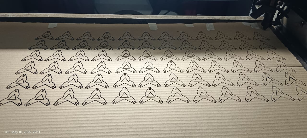
After that, I set the origin point on the laser machine and checked the frame to ensure the design fit properly on the cardboard sheet. Once everything was aligned, I selected the file to start the cutting process. The results of the cut are shown in the image below.
|
|
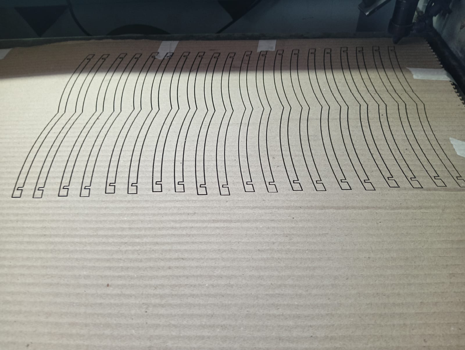
Below, I am showing how the cutting process started and how it was completed successfully.
|
|
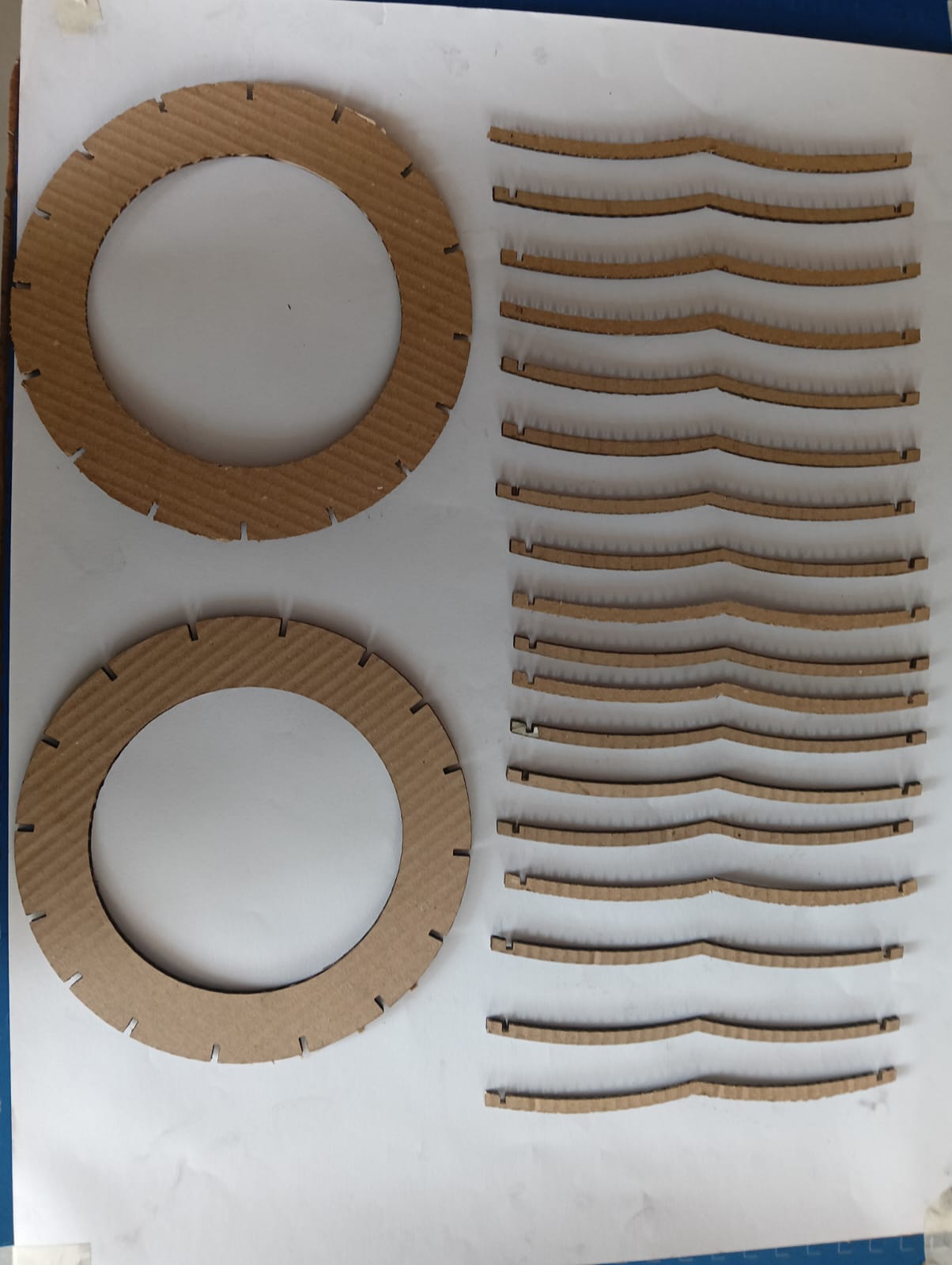
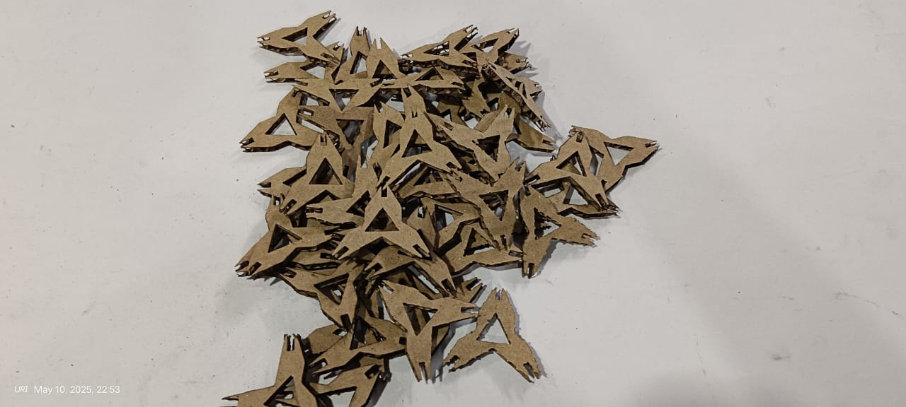
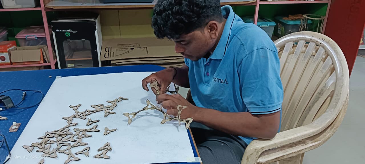
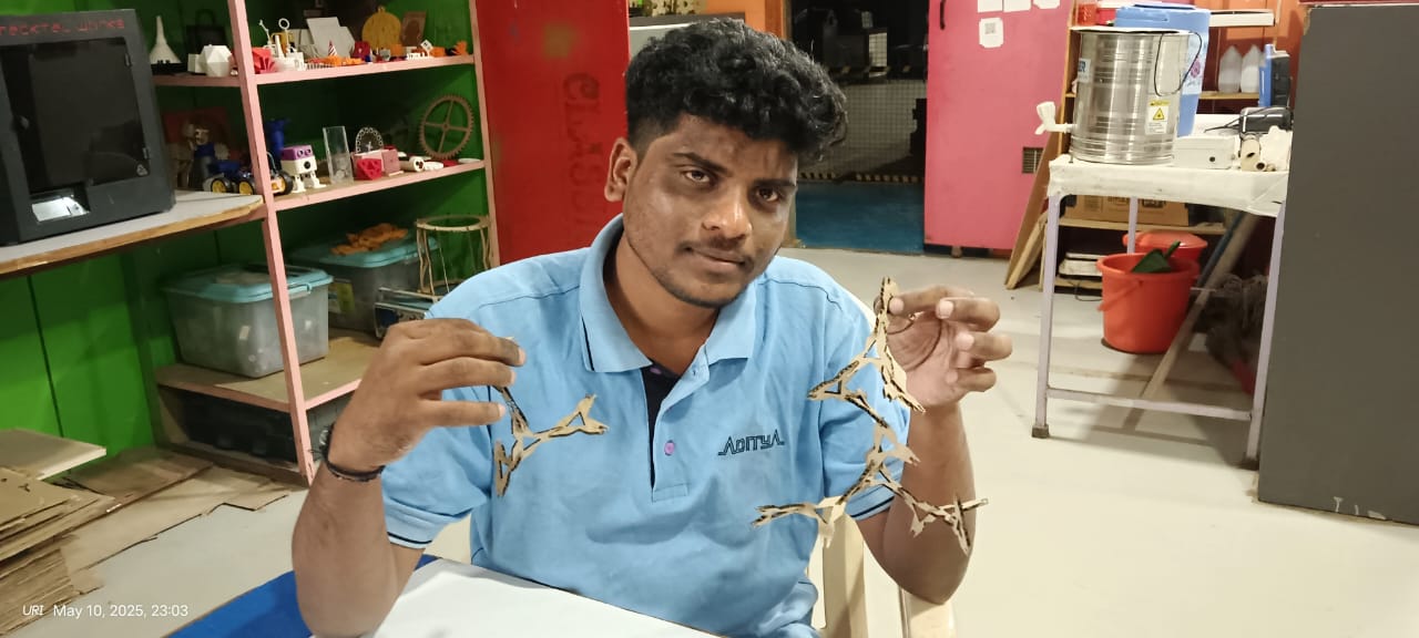
After completing the cutting process, I collected all the pieces and began the assembly.
|
|
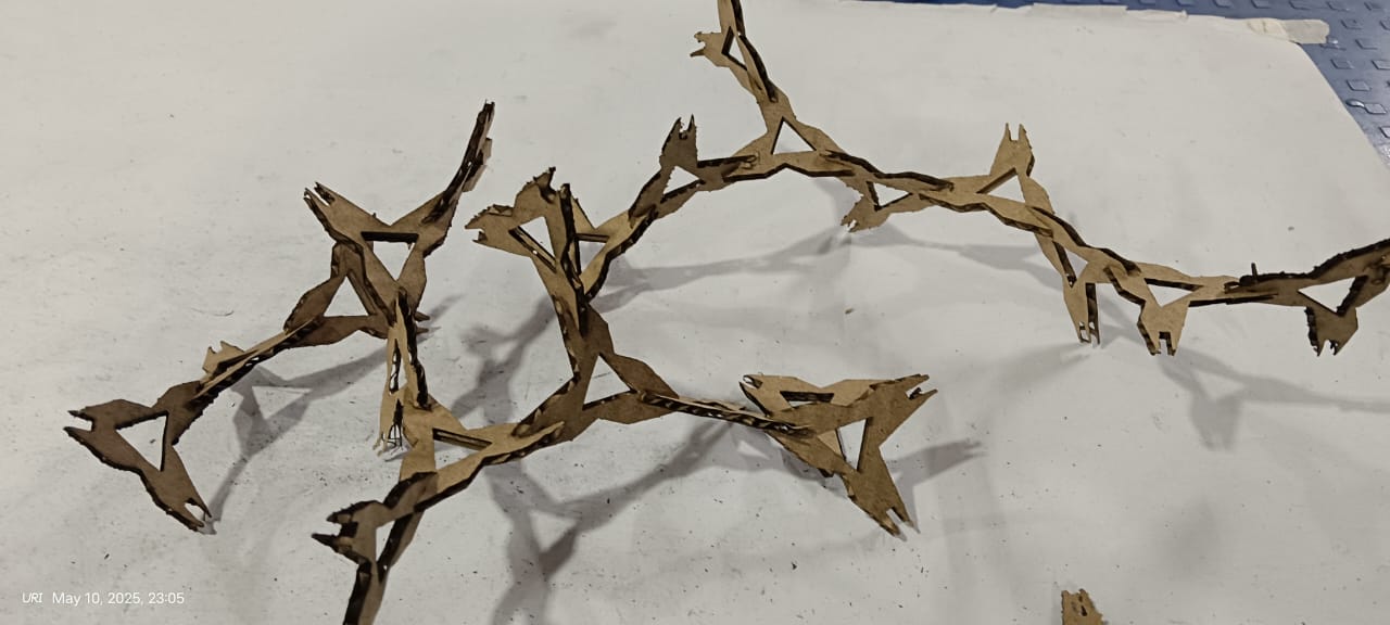
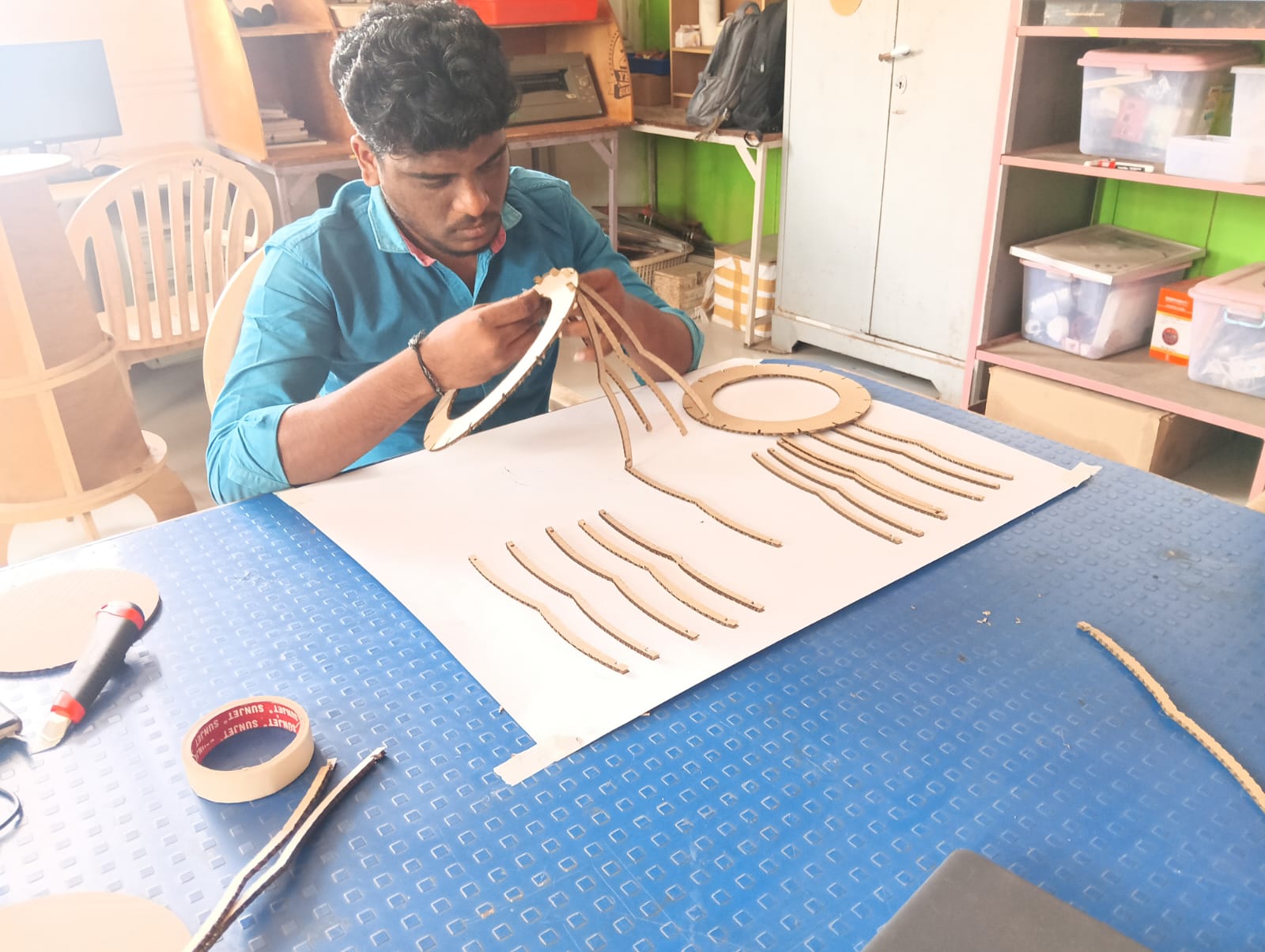
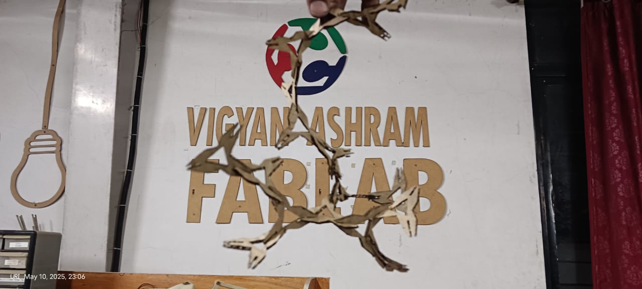
The results are shown below. They look very good and unique, and I was able to assemble them in a way I hadn't initially anticipated during the design process.
|
|
|
|
Vinyl Cutting :
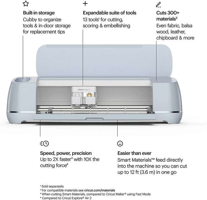
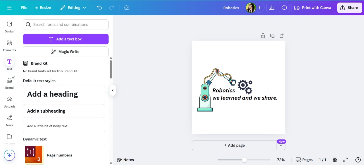
After completing the laser cutting, I started working on vinyl cutting. For this, I created my own design using Canva. In my case, I am using the Cricut Maker 3 vinyl cutter to cut my design.
Cricut Maker 3
References: Reference
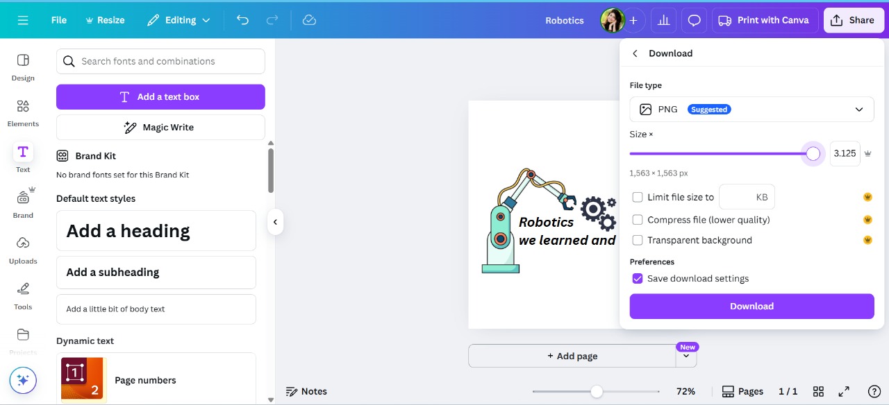
First, I designed my graphic using Canva and downloaded it as an image. Below, I am showing the design.
|
|
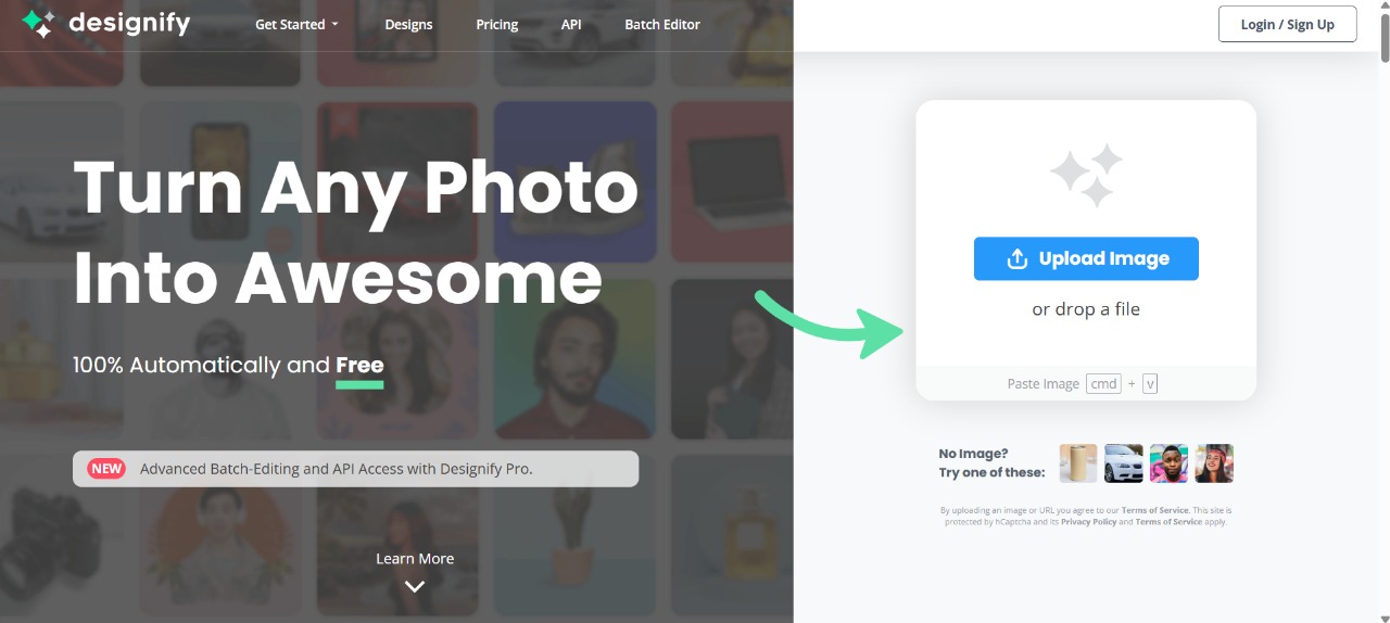
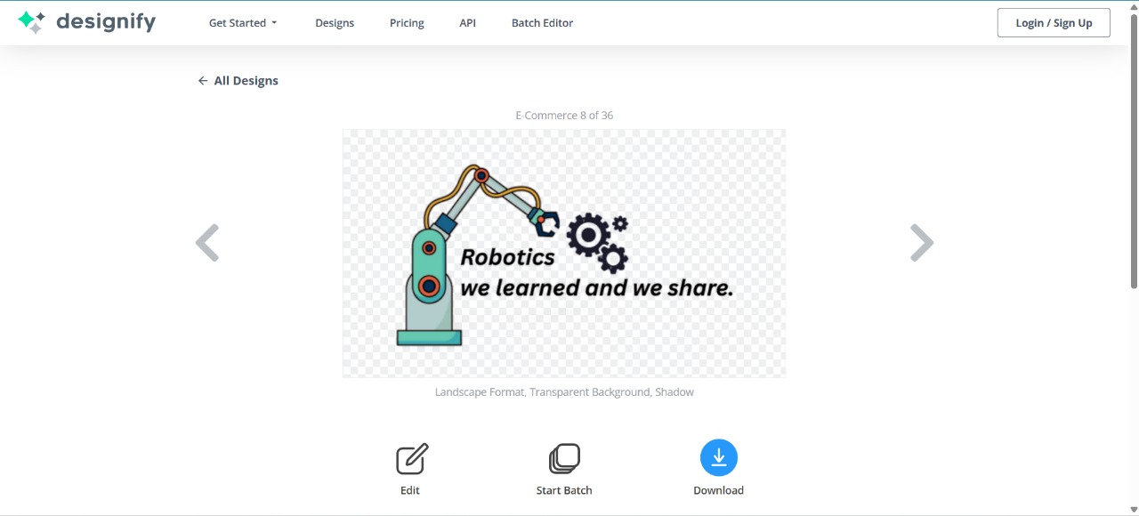
After that, I used Designify to convert the image into an outline. For this, I used the tool shown below and then downloaded the result.
|
|
After that, I used Cricut Design Space software to control my machine. I imported my design into it.
|
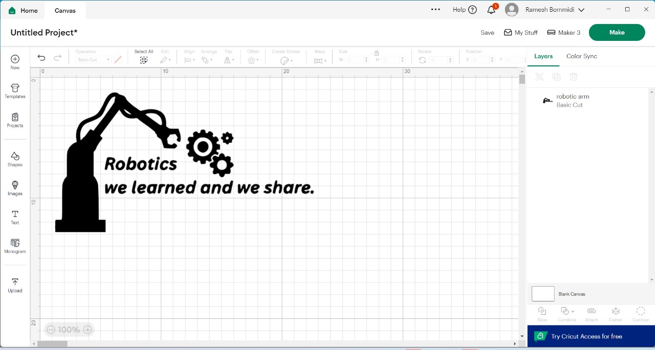
|
After that, I connected the machine and started the cutting process. Below, I am showing that
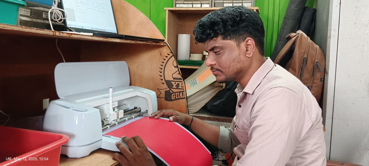
|
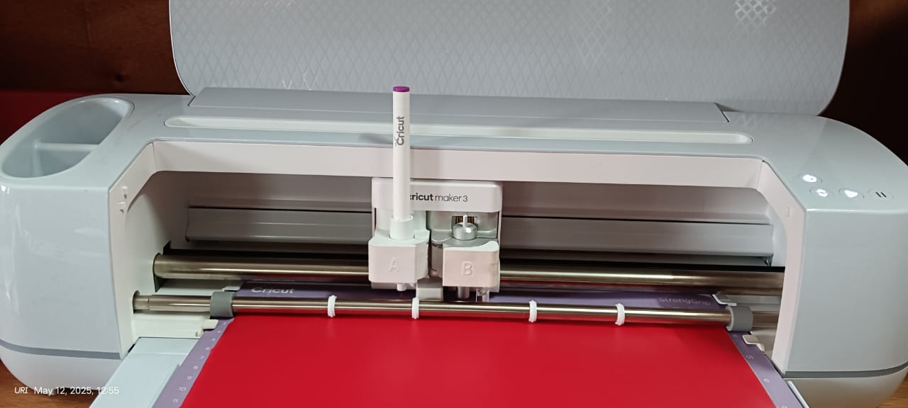
|
Below, I am showing the final output of my vinyl cutting.
|
|

|
Parametric Design with Multiple Assembly Options :
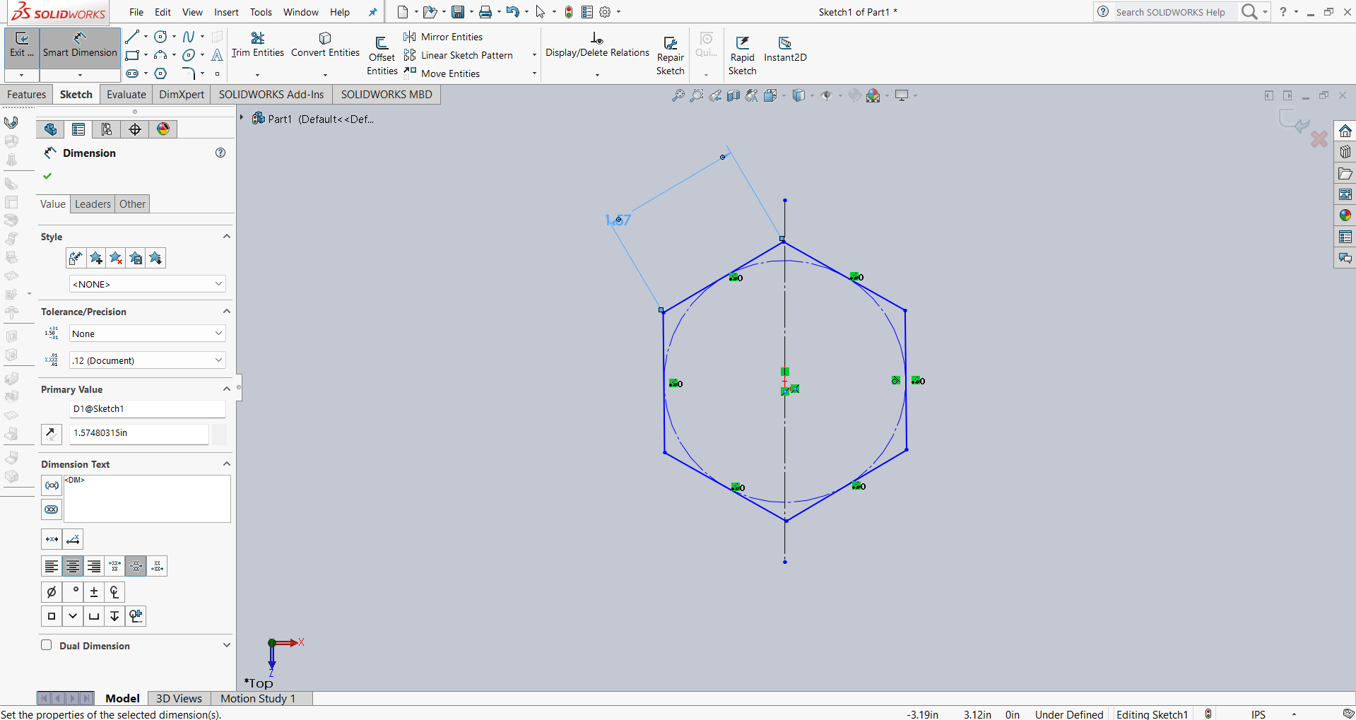
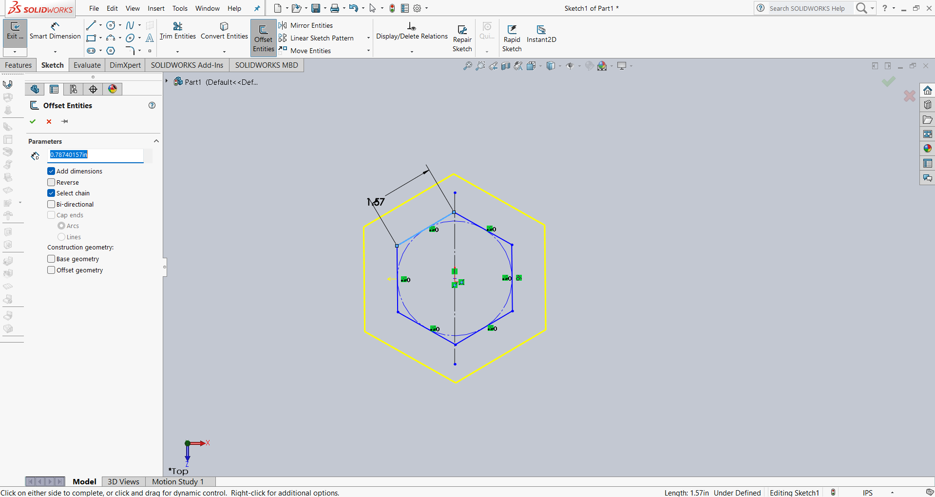
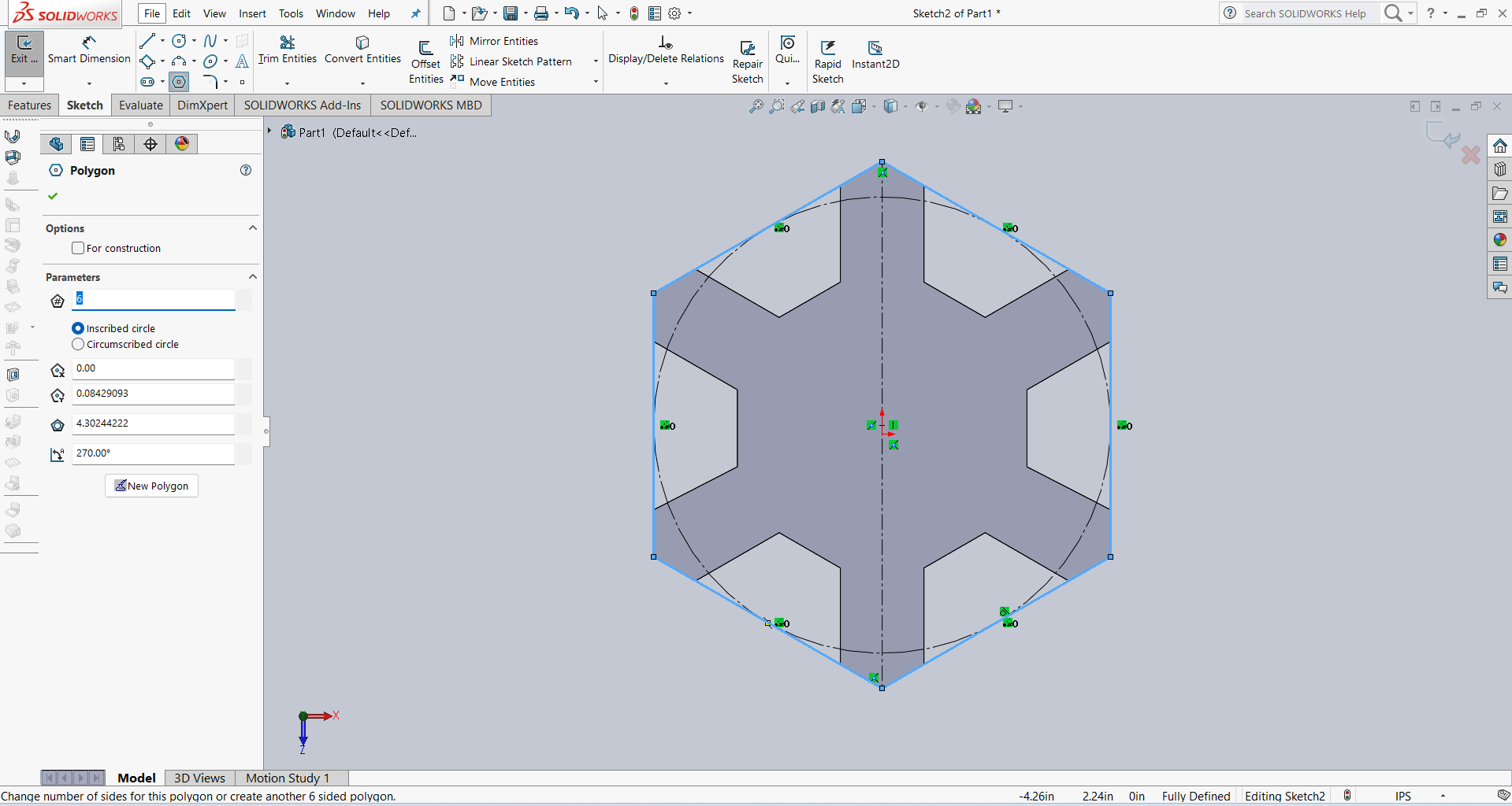
Here is one more parametric design that I am documenting. In the previous one, I did not design it in a parametric way. So, in this documentation, I am explaining how I created the design using parametric options. First, I decided to create two hexagons, where one hexagon is touching the other. To achieve this, I started by creating a single hexagon. Then, I used the offset tool to create another hexagon with a 20 mm offset. The image below shows the result.
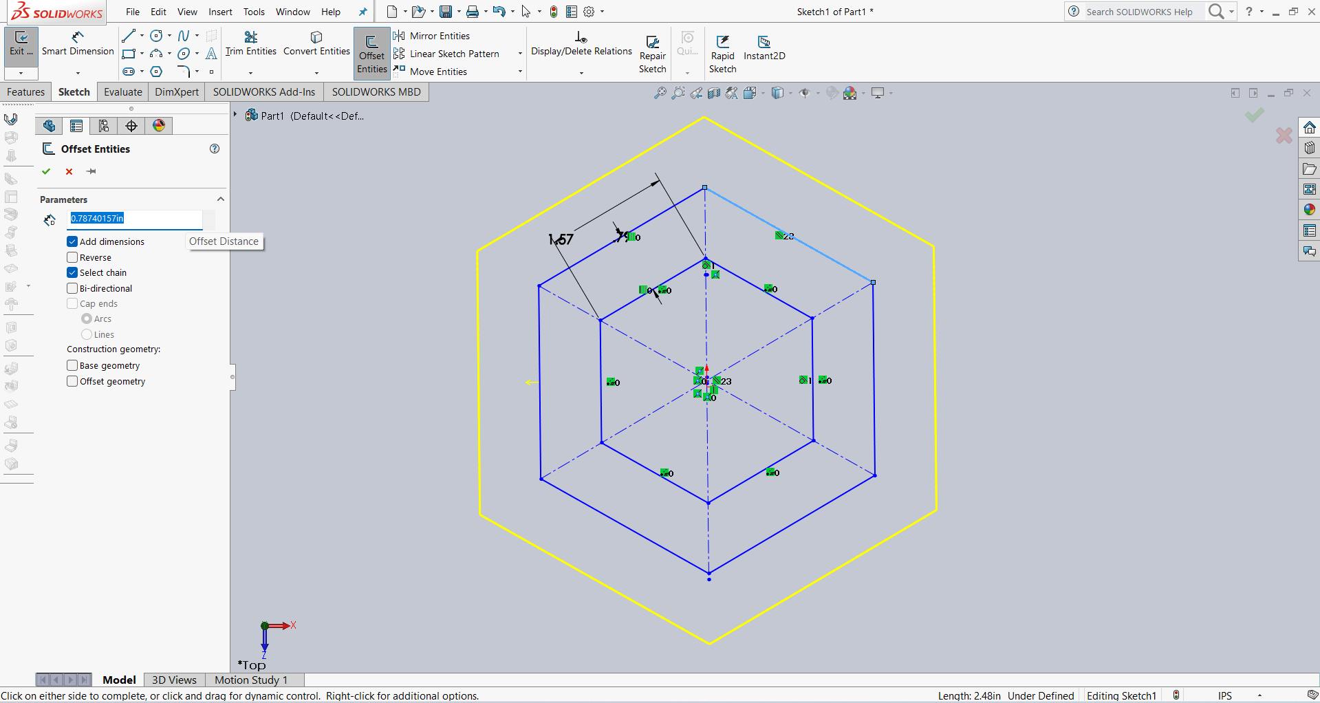
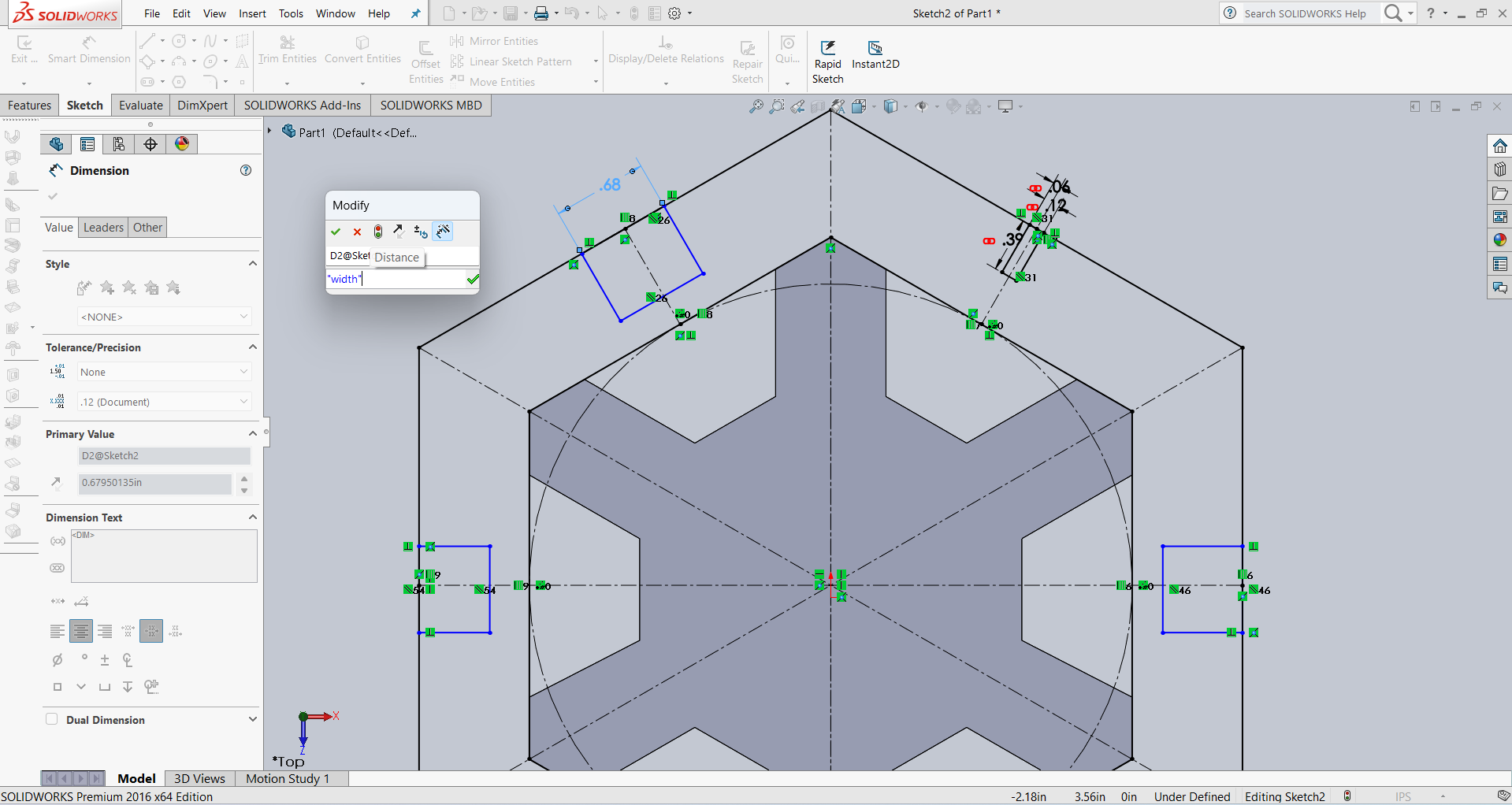
After that, I applied dimensions as shown in the image. Then, I created one more hexagon outside the original hexagon using the offset tool with a 20 mm distance.
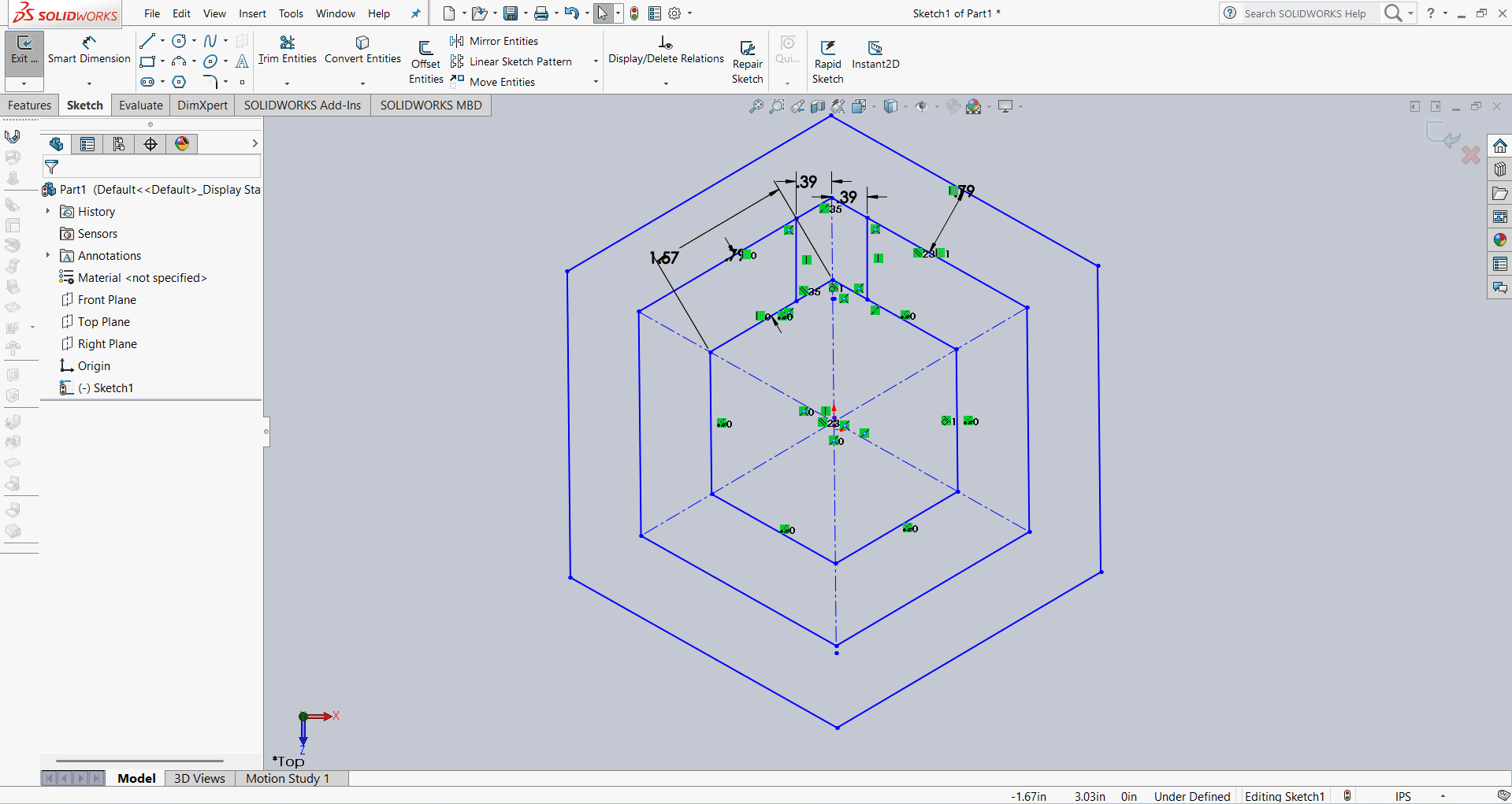
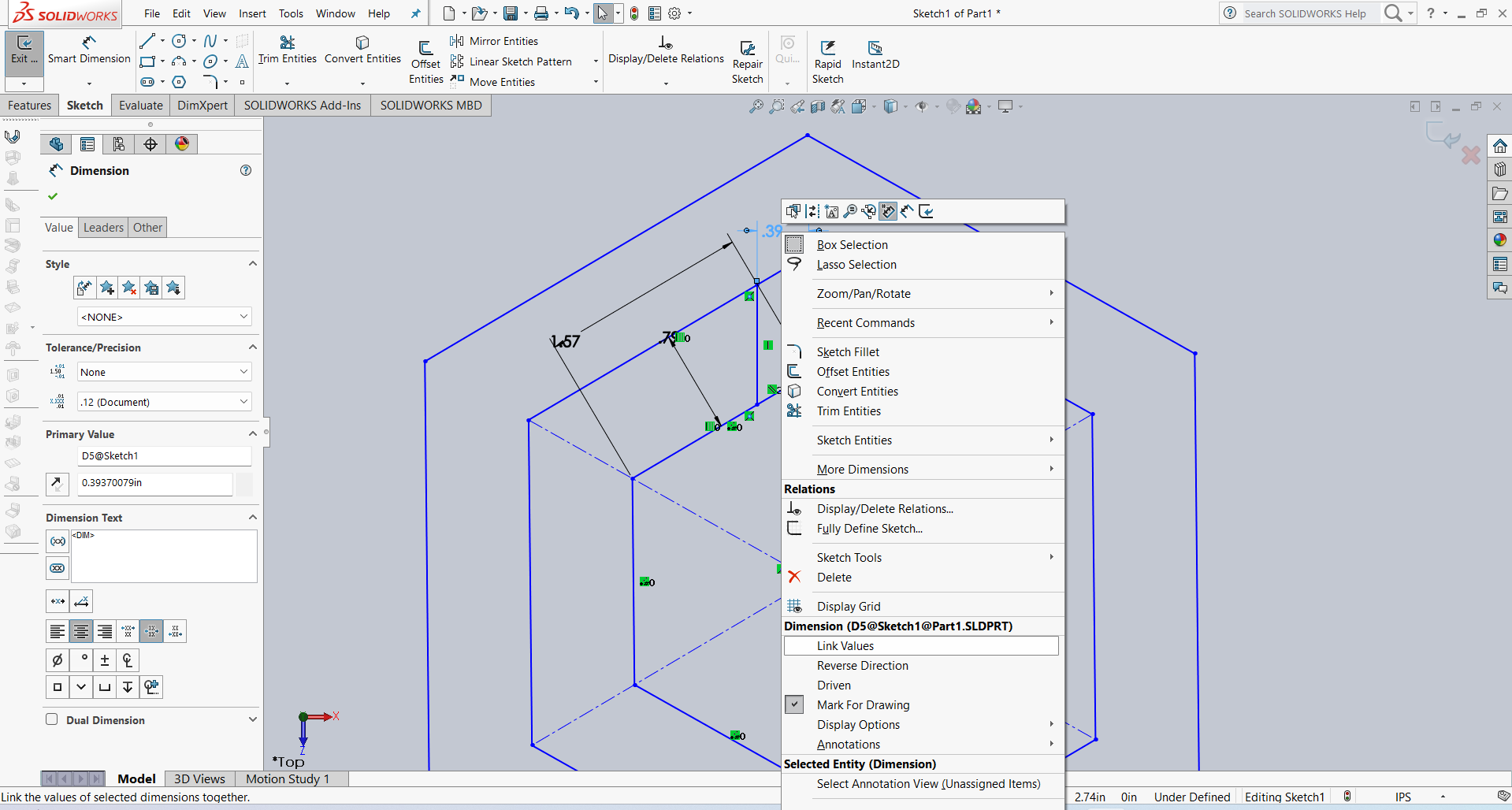
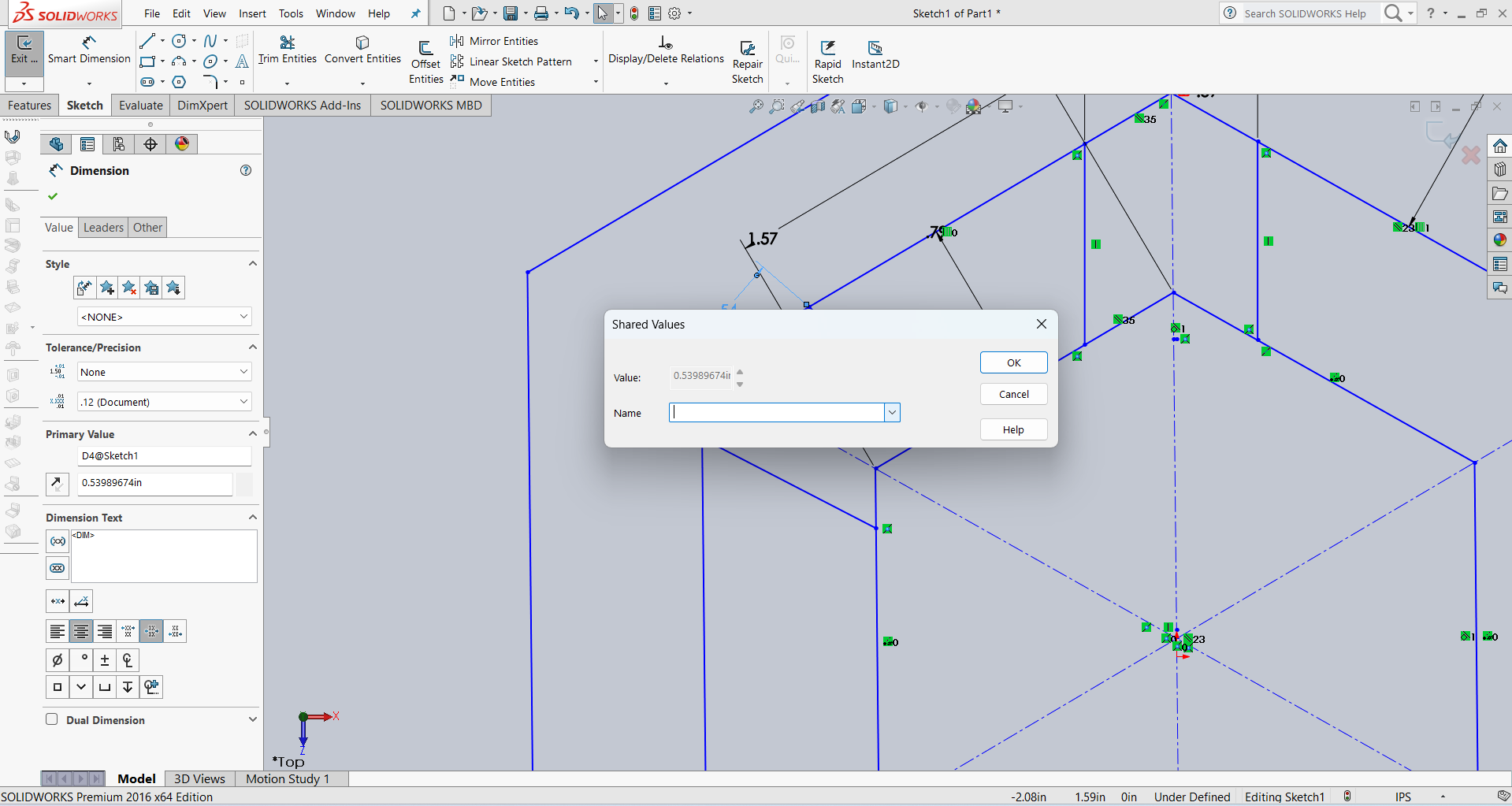
After that, I linked the dimensions using parameter names for better control and flexibility. Below, I am showing how I linked the dimensions.
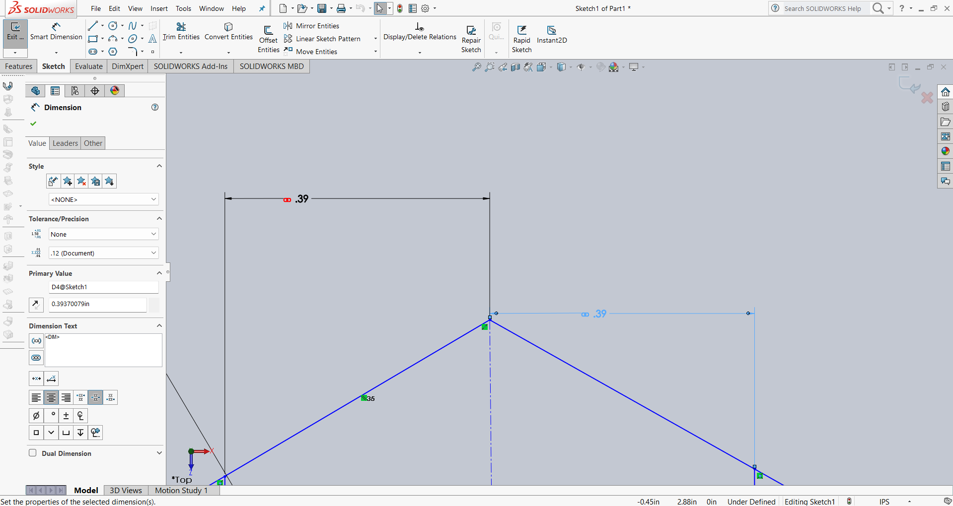
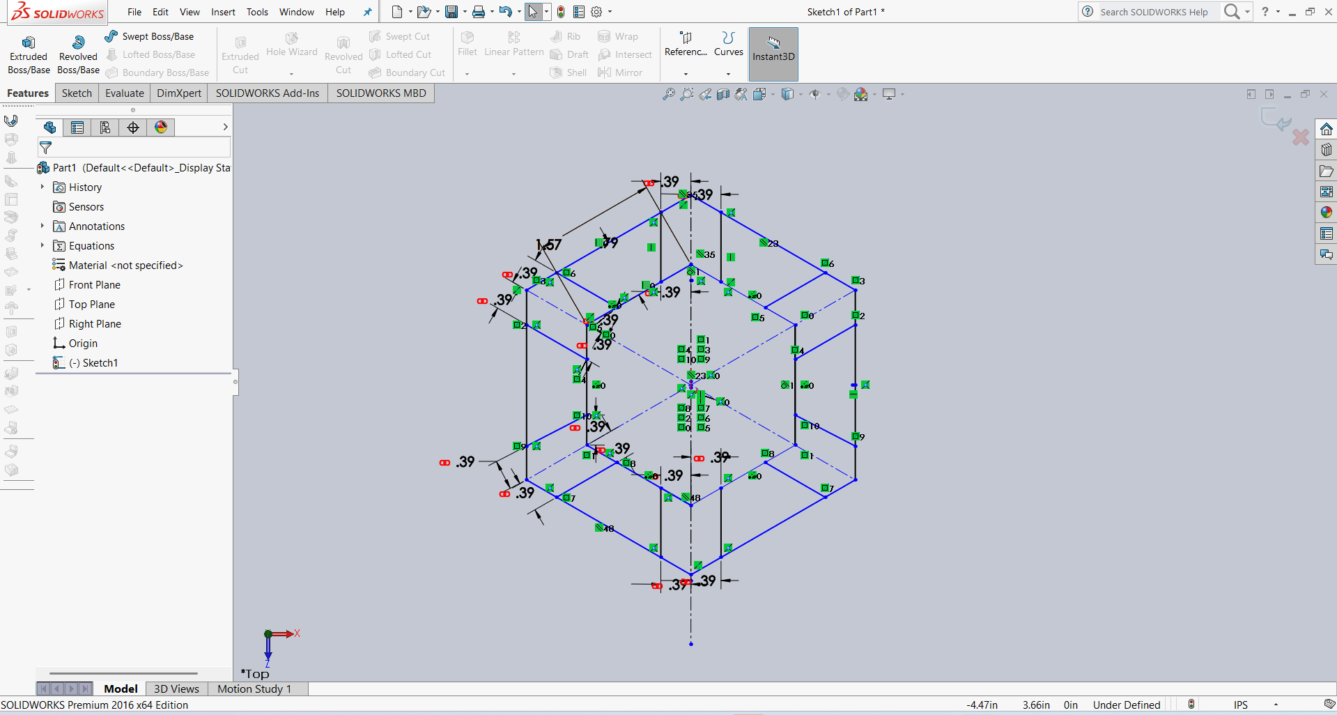
Below, I am showing how my design looks after linking the dimensions. All the dimensions are linked as shown in the image.
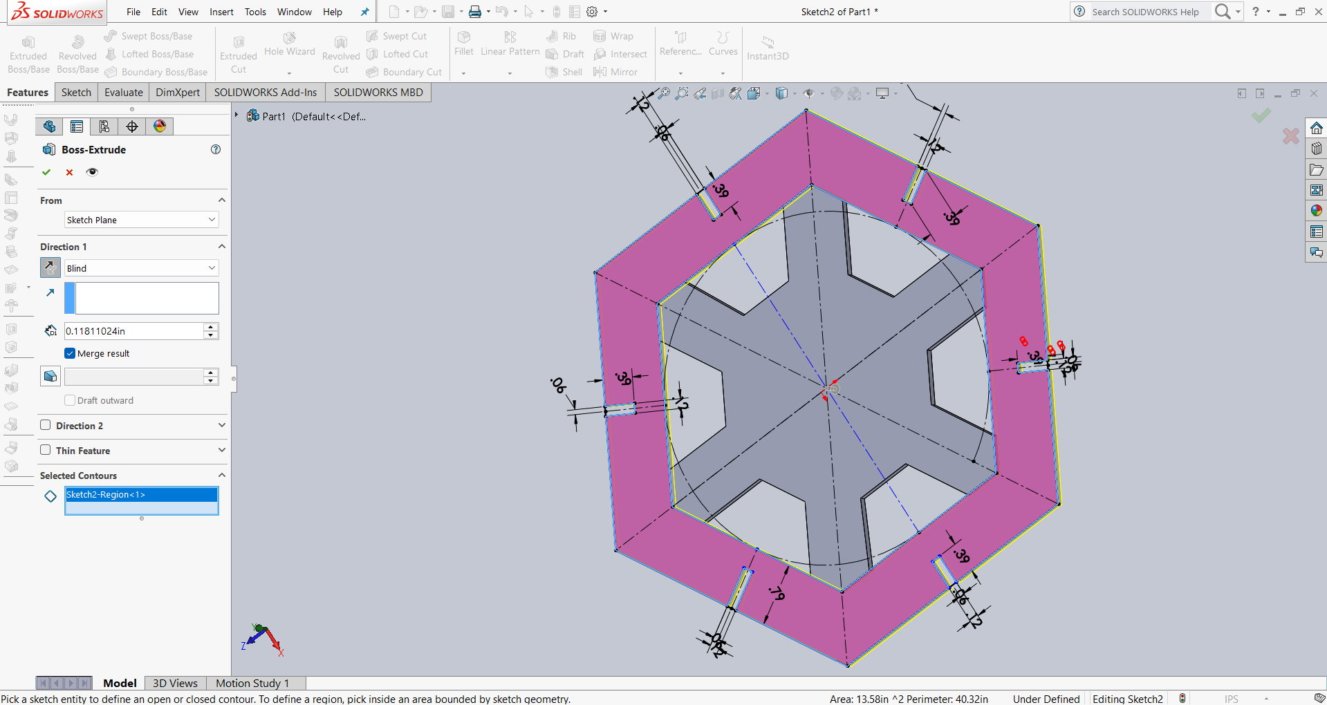
After that, I used the Extrude option to give the design thickness. The result is shown in the image below.
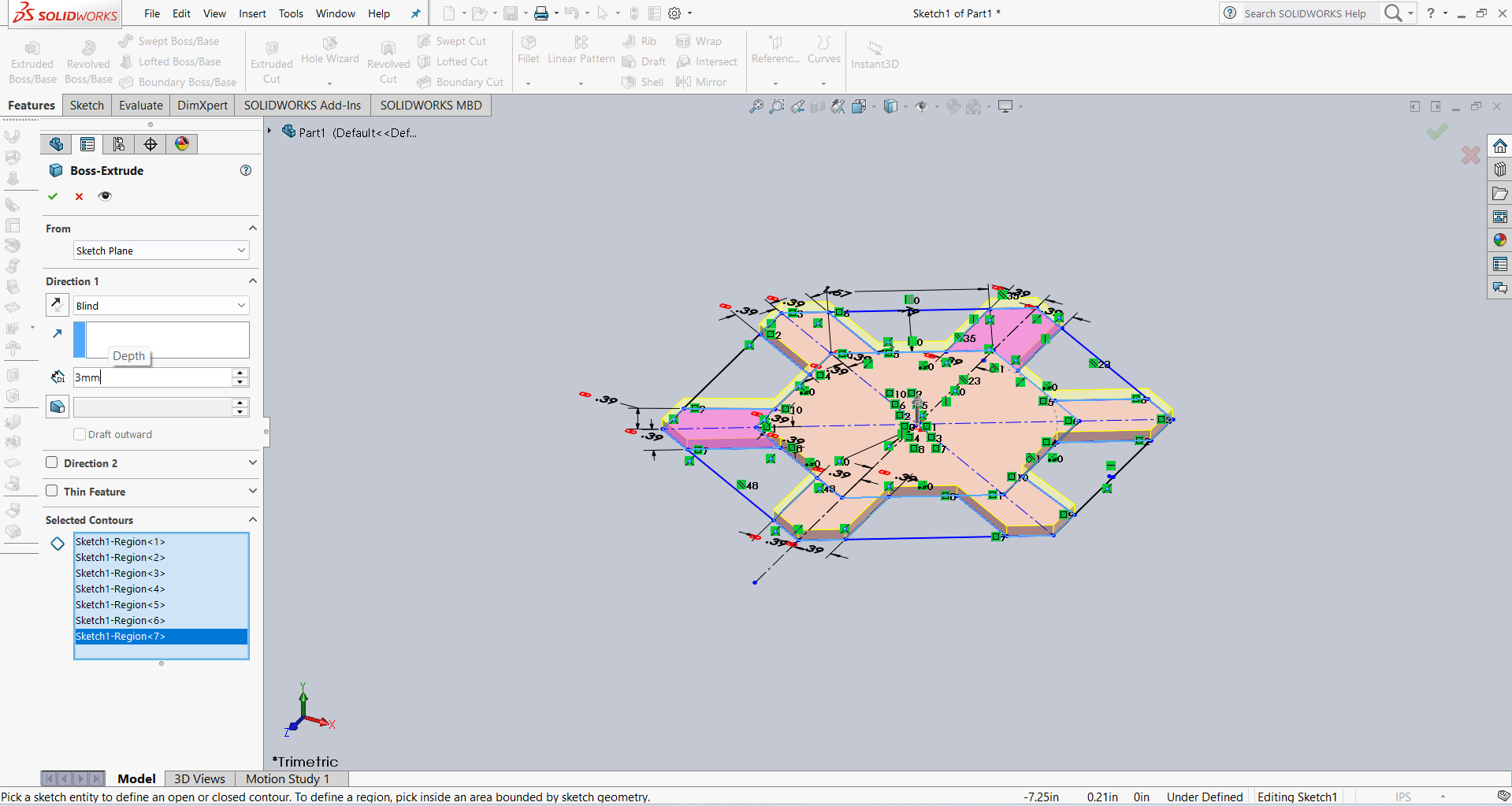
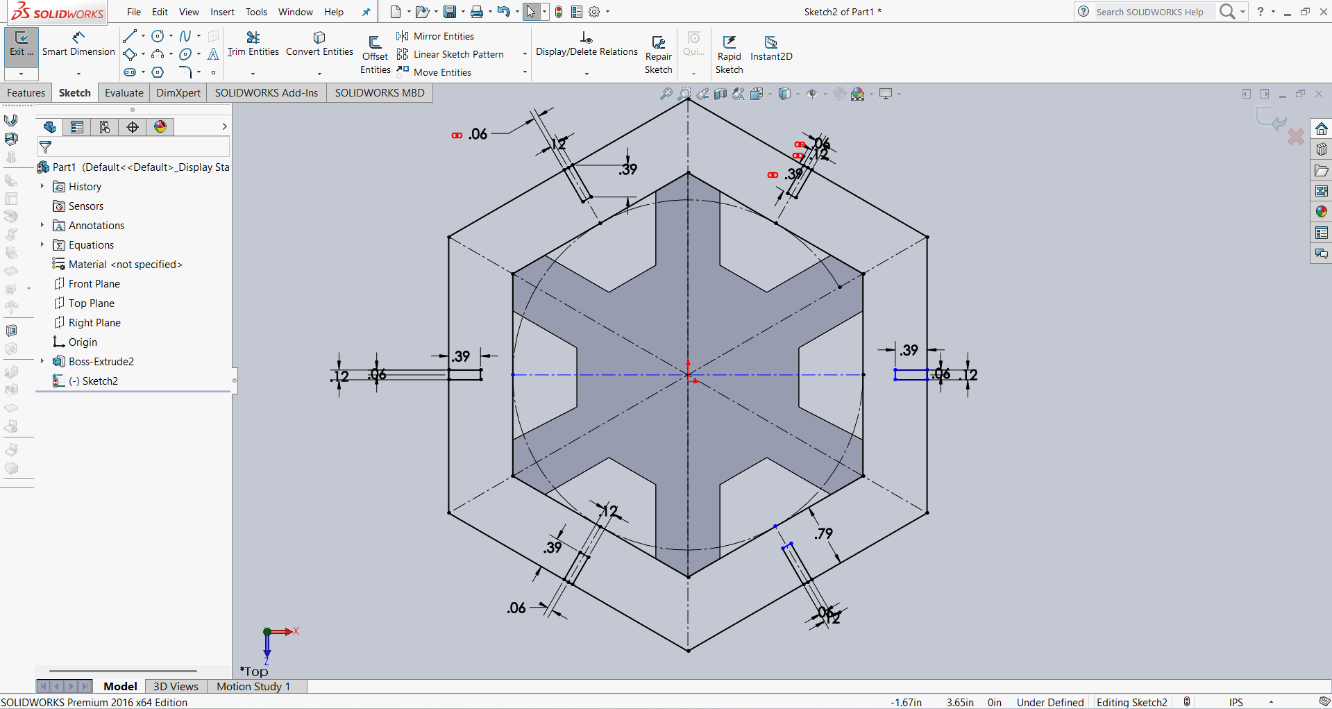
After that, I created an outer hexagon for the slots. I then added several slots and applied dimensions using parametric options. The result is shown below.
After that, I linked all the slot dimensions according to my requirements using parametric constraints. Then, I performed the extrusion using the Extrude feature. The result is shown in the image below.
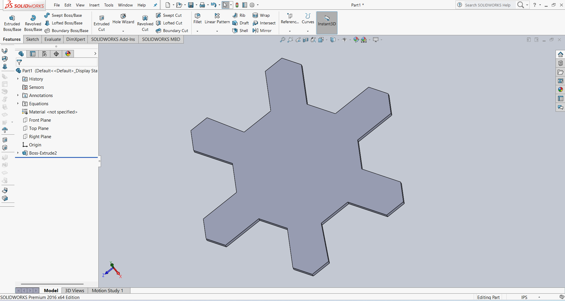
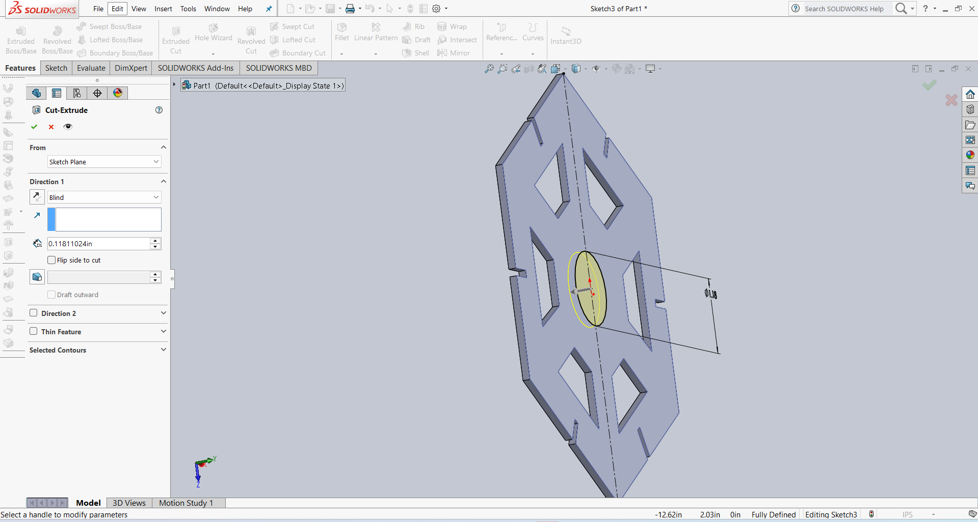
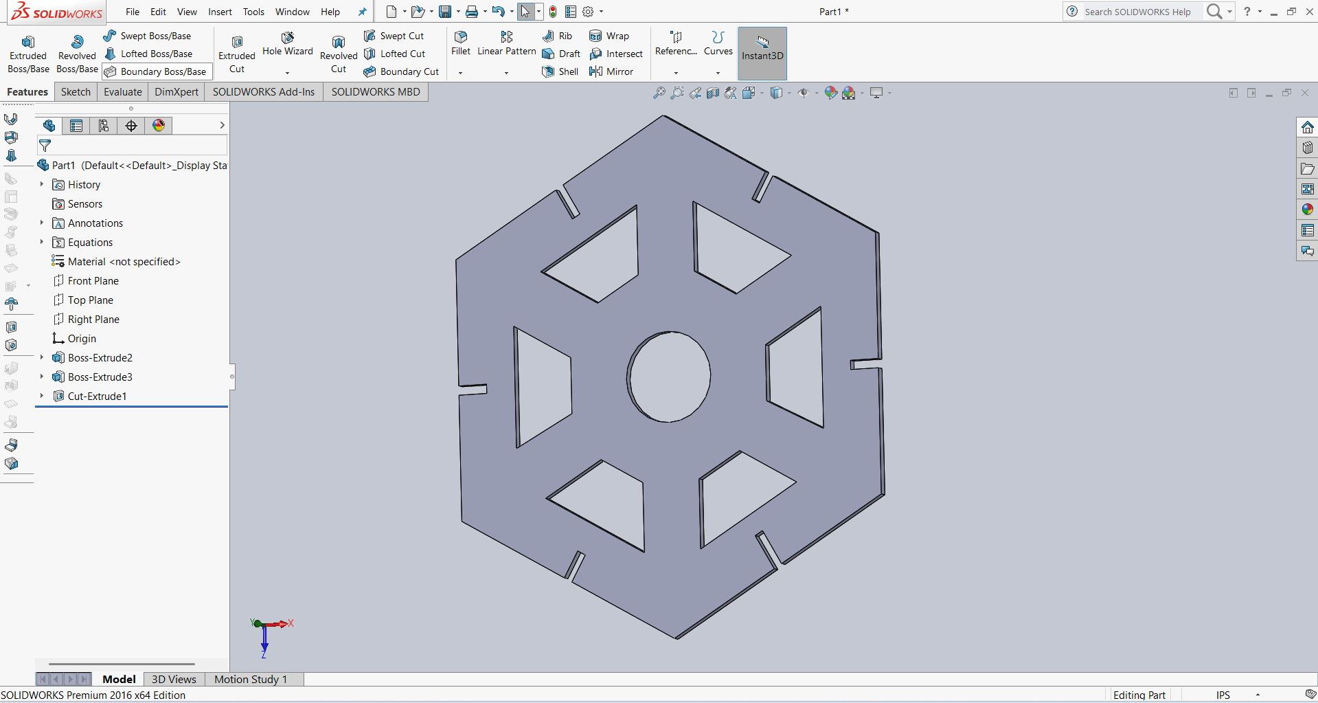
For design and visual purposes, I created a circle in the idle area and then extruded it. The result is shown below.
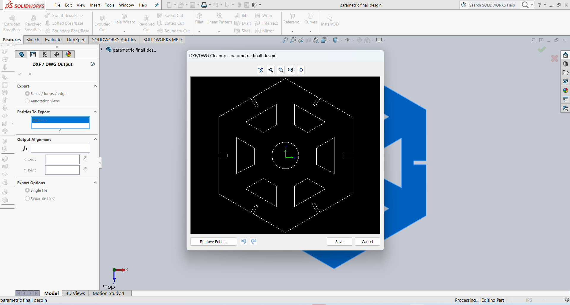
I am showing the final results below.
After that, I saved my design in DXF format, and it is ready for cutting.
After that, I used RD Works to generate the tool path, and then I cut 12 pieces.
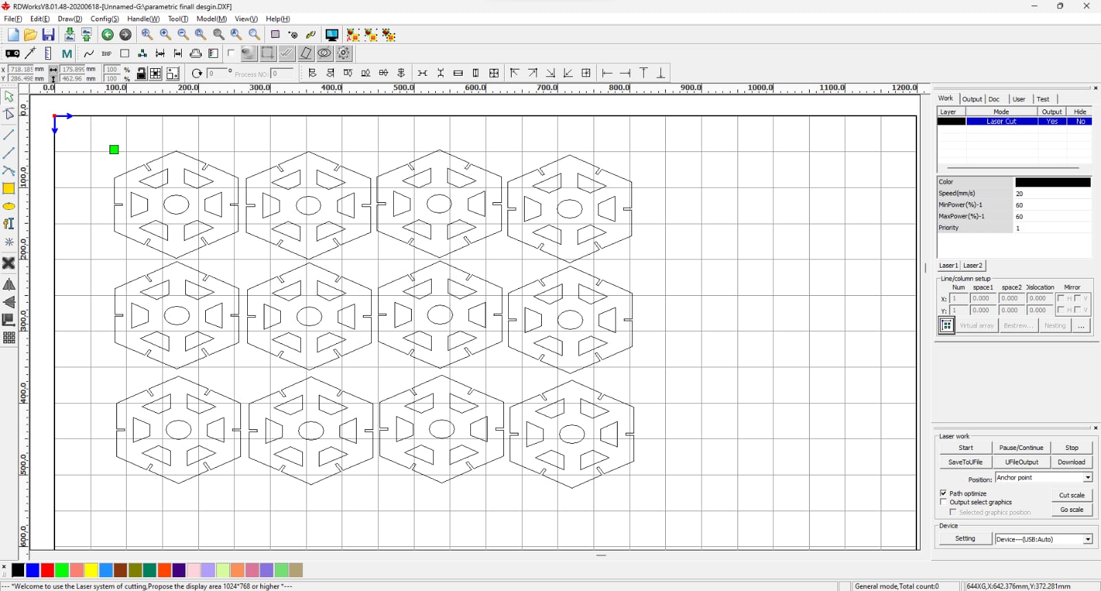
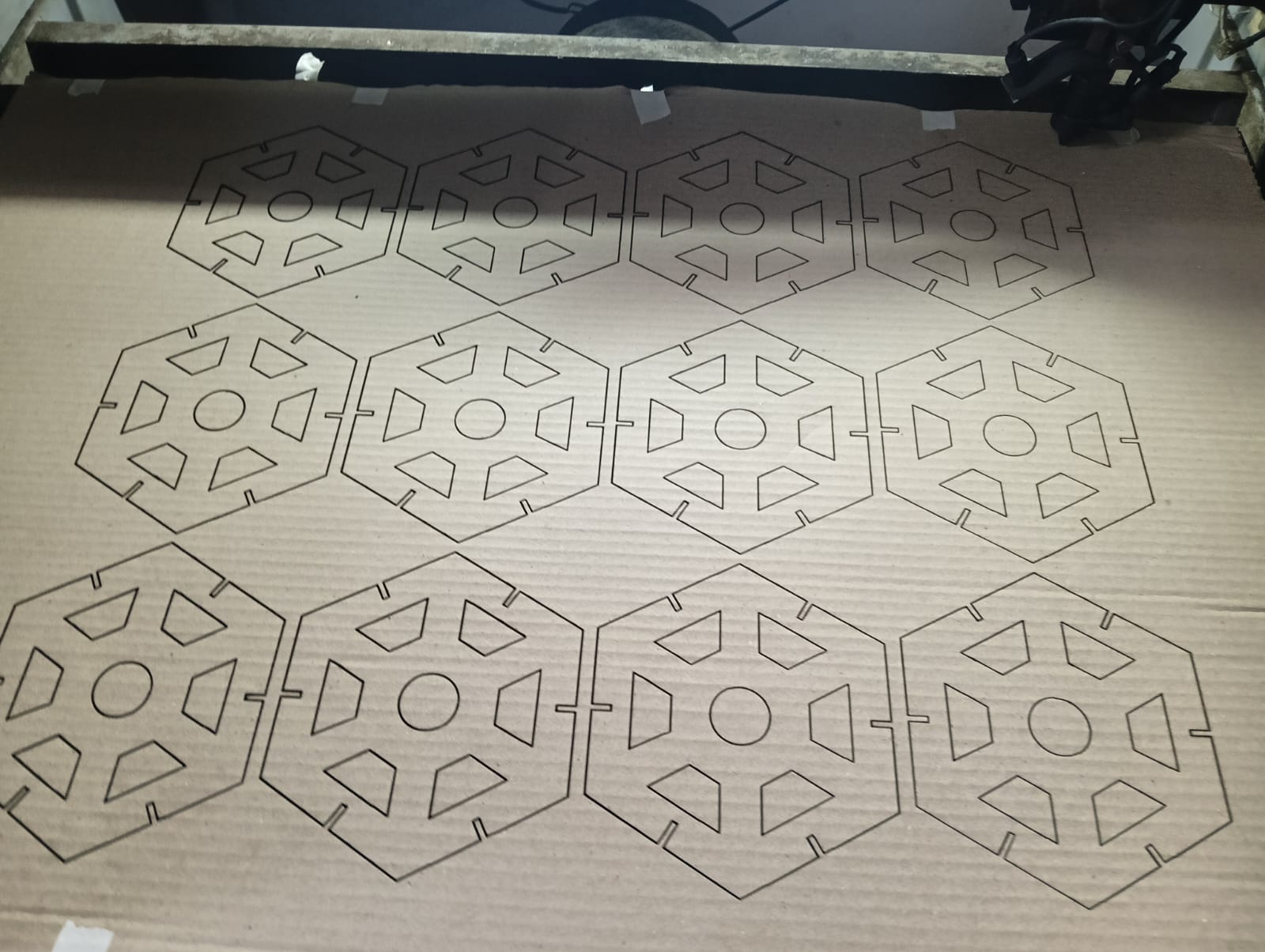
After generating the tool path, I started the cutting process.
Below, I am showing how the laser cut my design with very good quality.
I removed all the cut pieces and started the assembly.
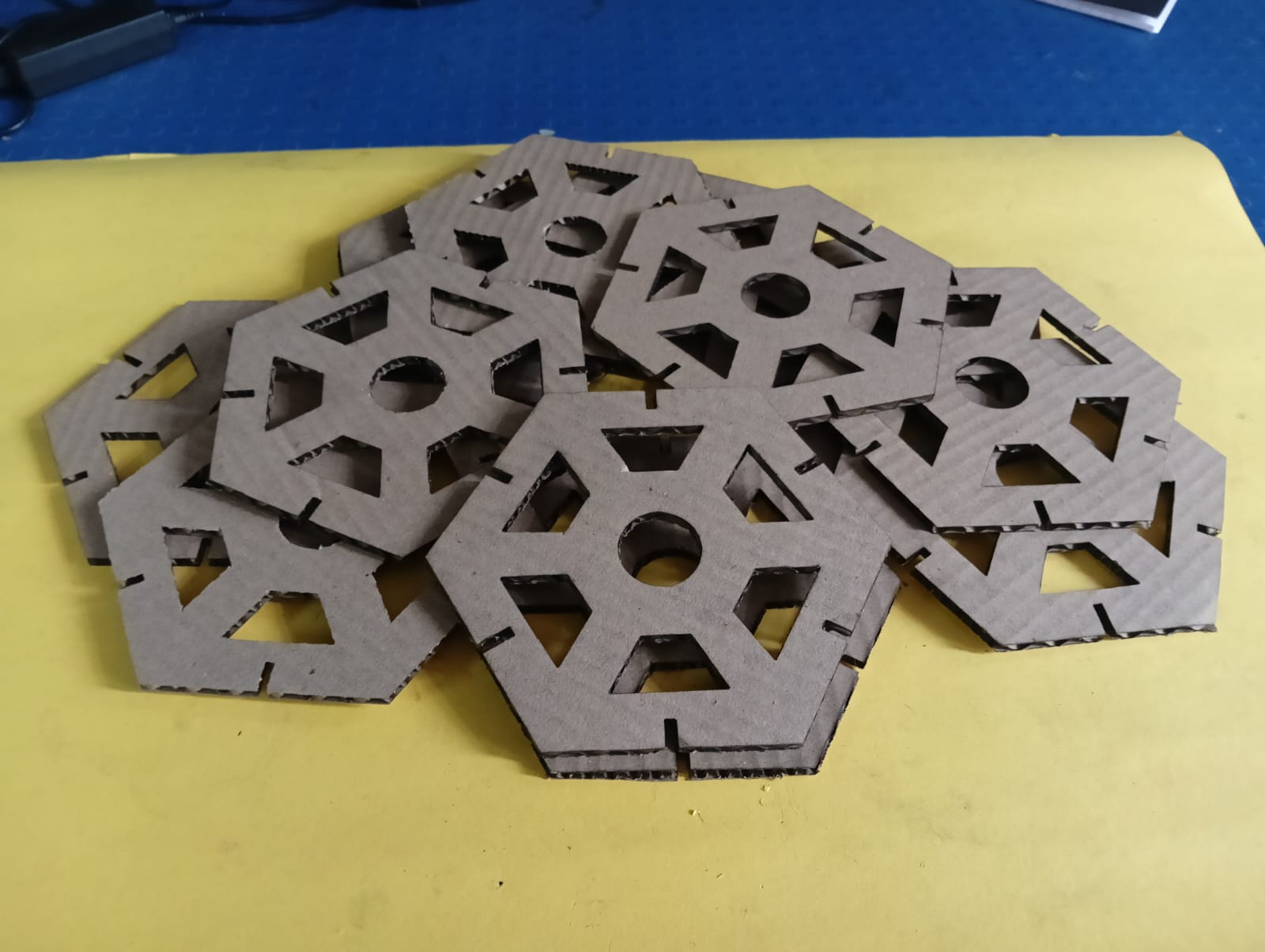
I carefully assembled the parts.
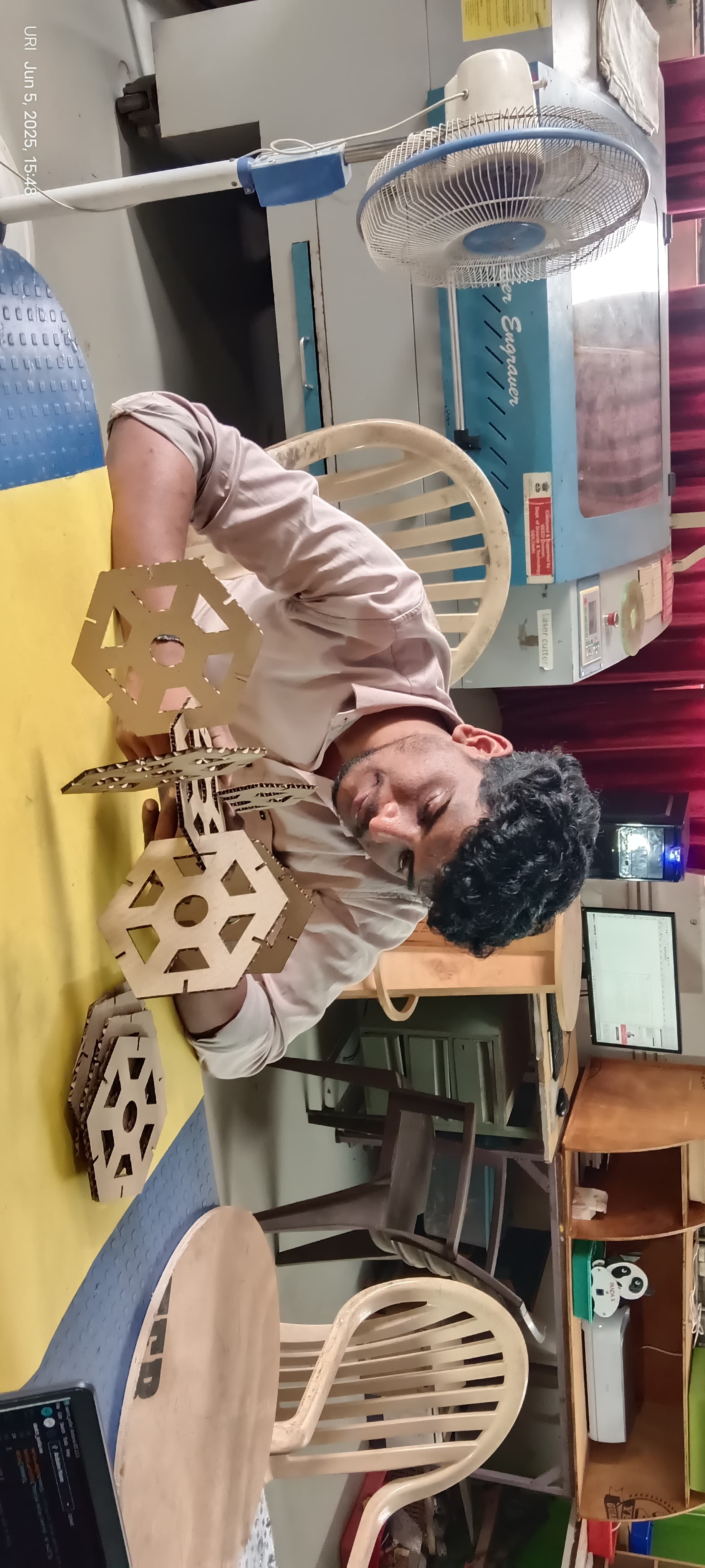
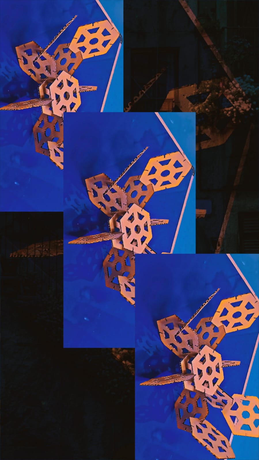
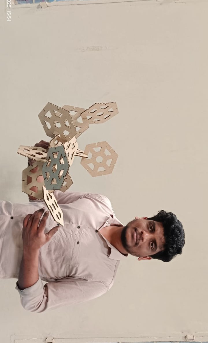
I am showing the final results below
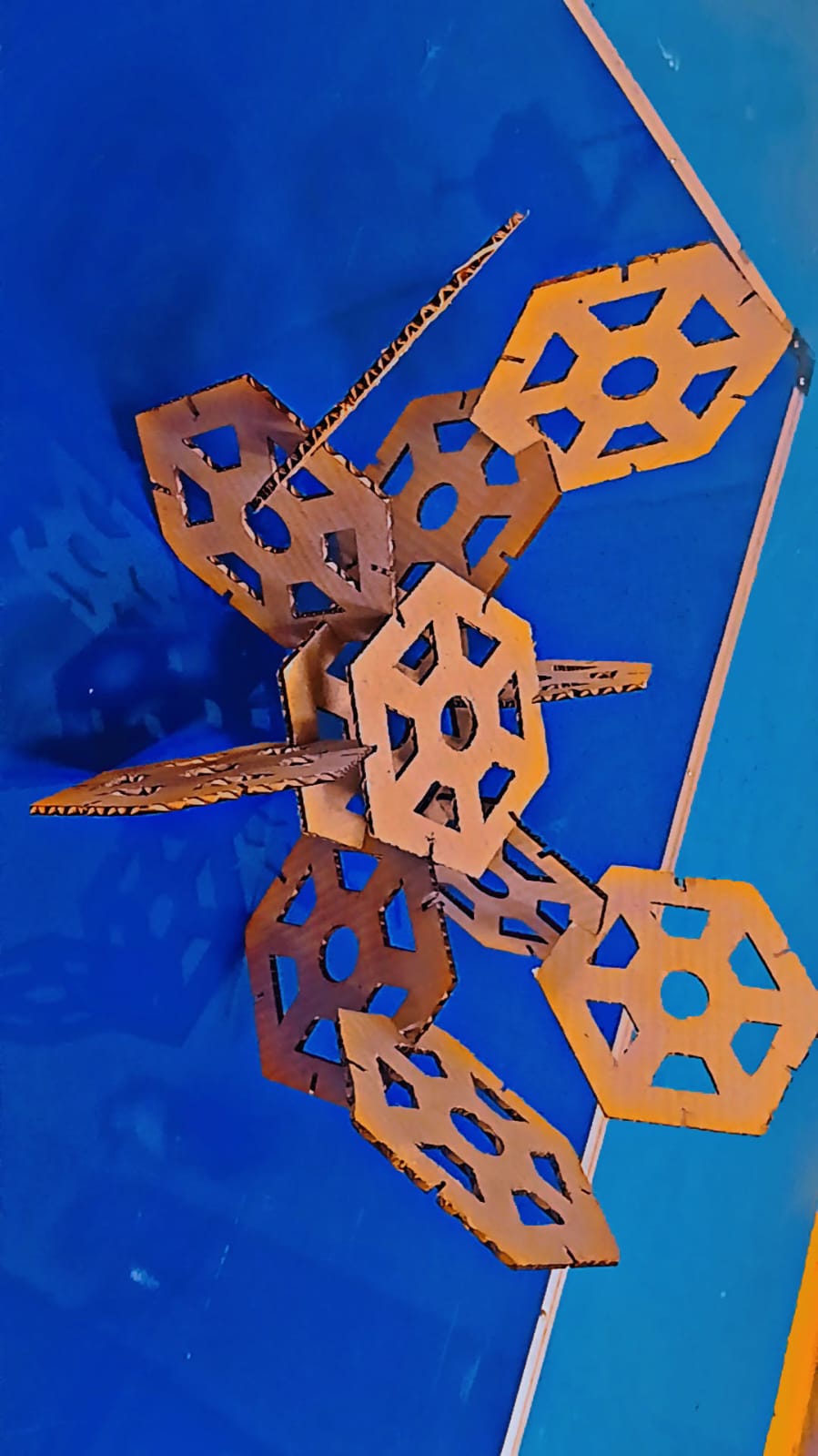
Using the parametric option ensured highly accurate dimensions, and the slots were cut precisely. I sincerely thank Jorge Valerio for his valuable feedback this week — it helped me learn something new.
Positive Outcomes:
In this assignment, I gained new knowledge and hands-on experience. This was my first time operating both the laser cutter and the vinyl cutting machine. I learned how to design, prepare files, and safely use these digital fabrication tools. It was exciting and rewarding to see my own designs turned into physical outputs. I am very happy to have learned these new skills this week, which boosted my confidence in using fabrication machines.
Challenges Encountered:
In this assignment, I did not face many major challenges overall. However, while working on the laser cutting part, I struggled with getting the correct fit for the assembly. I had to redesign and test the parts three times before achieving the proper fit on the fourth attempt. This process taught me the importance of precision and tolerances in digital fabrication. It was a valuable learning experience in improving my design accuracy.
Original Files for download:
- Download link for SolidWorks file
- Download ring for SolidWorks file
- Download link for DXF Format
- Download Ring for DXF Format
- download full assembly file
- Download parametric design for a triangle SolidWorks file
- Download parametric design for a triangle for DXF Format
- Download Vinyl Cutting design
- Download final parametric design SolidWorks file
- Download final parametric design DXF file
- Download All Files