Assignment 7: Computer-Controlled Machining
This assignment is about documenting my knowledge gained in Computer-Controlled Machining. It includes learning the basics of CNC machining, following safety guidelines, and working with various materials such as cardboard, MDF (Medium Density Fiberboard), MDO (Medium Density Overlay), and OSB (Oriented Strand Board). Additionally, it covers understanding the required machining tools, designing press-fit joints in SolidWorks, and exploring effective design strategies for creating strong and reliable press-fit assemblies.
Highlight Moments of the Week
Basics of Computer controlled machining
Computer-controlled machining is a process where machines like CNC mills, lathes, and routers are operated using digital instructions. It allows for high precision and repeatability in cutting, drilling, and shaping materials like metal, wood, and plastic. The process starts with designing a part in CAD software, which is then converted into machine-readable G-code. CNC machines follow these coded instructions to perform automated machining operations with minimal human intervention. This technology is widely used in manufacturing, prototyping, and custom fabrication.
Before starting this week's assignment, I am explaining the CNC router I am using and the safety precautions I have taken. I have written them below.
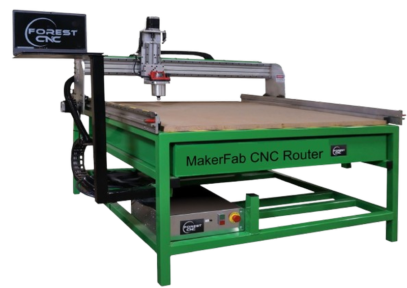
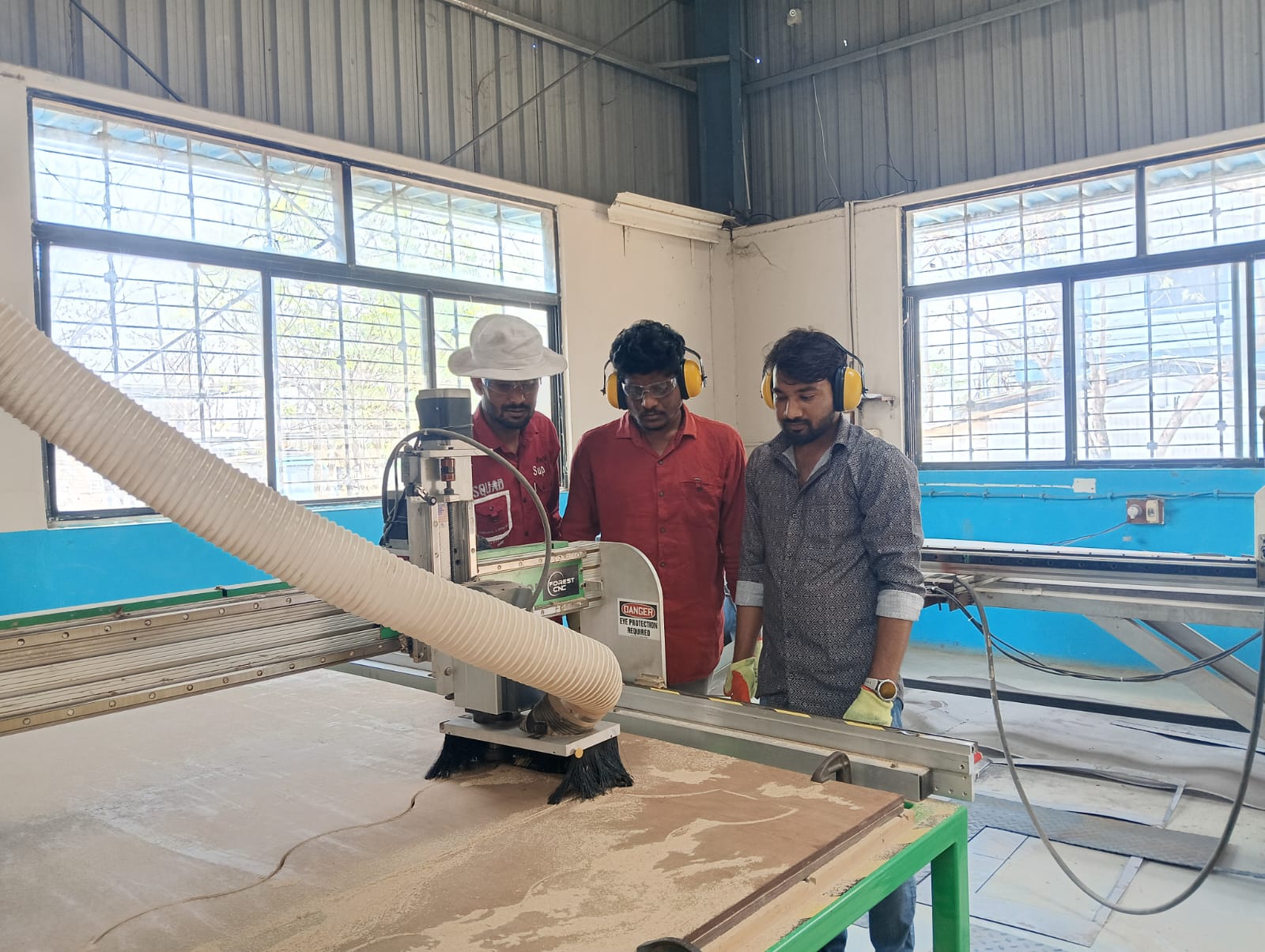
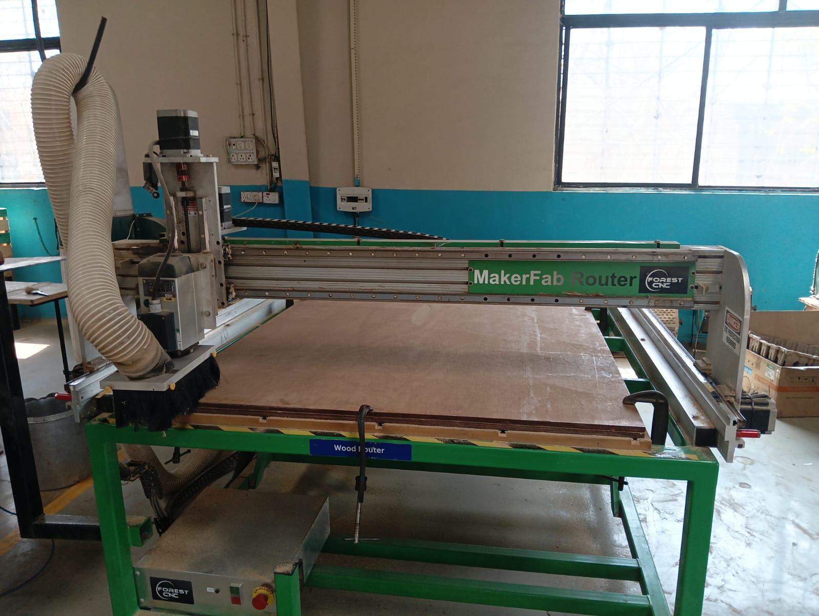
Forest CNC Router:
The Forest CNC Router is a high-precision machine used for cutting, engraving, and milling various materials like wood, acrylic, and aluminum. It features a sturdy frame, ensuring stability and accuracy during operation. The router is equipped with a powerful spindle motor that enables smooth and efficient cutting. It supports computer-controlled operations, allowing users to create complex designs with ease. Additionally, it includes safety features like emergency stop buttons and dust collection systems to maintain a clean workspace. For more information
Features of the Forest CNC Router:
- High Precision Cutting – Ensures accurate and smooth cuts on various materials.
- Robust Build Quality – Sturdy frame for stability and long-lasting performance.
- Powerful Spindle Motor – Capable of handling different materials like wood, acrylic, and aluminum.
- Computer-Controlled Operation – Supports G-code for precise automation and intricate designs.
- User-Friendly Interface – Easy-to-use software for beginners and professionals.
- Safety Features – Includes emergency stop buttons and protective enclosures.
- Dust Collection System – Helps maintain a clean working environment.
- Multiple Tool Compatibility – Supports different tool bits for various cutting and engraving needs.
Forest CNC Router Specifications
| Category | Specification |
|---|---|
| Construction and Frame |
Material: Heavy-duty steel or cast iron Table Size: 2’x3’ to 5’x10’ or larger Frame Type: Welded and reinforced for vibration resistance |
| Spindle |
Power: 2.2 kW to 12 kW Speed: 6,000 to 24,000 RPM Cooling System: Air-cooled or water-cooled |
| Motion System (Axes) |
Number of Axes: 3-axis (X, Y, Z), optional 4th-axis (rotary) Movement Mechanism: Ball screws or rack & pinion drive Resolution: 0.01 mm or better |
| Controller & Software |
Controller Type: Dedicated CNC or PC-based Software Compatibility: AutoCAD, SolidWorks, VCarve, Fusion 360, Aspire, etc. User Interface: Touch screen or handheld pendant |
| Cutting Area |
Standard Dimensions: 4’x8’ or custom sizes available Z-Axis Travel: Up to 12 inches |
| Additional Features |
Automatic Tool Changer (ATC): Available in higher-end models Dust Collection System: Built-in for a clean workspace Material Compatibility: Works with wood, plastics, composites, aluminum, foam, and more Safety Features: Emergency stop button, limit switches, and protective enclosures |
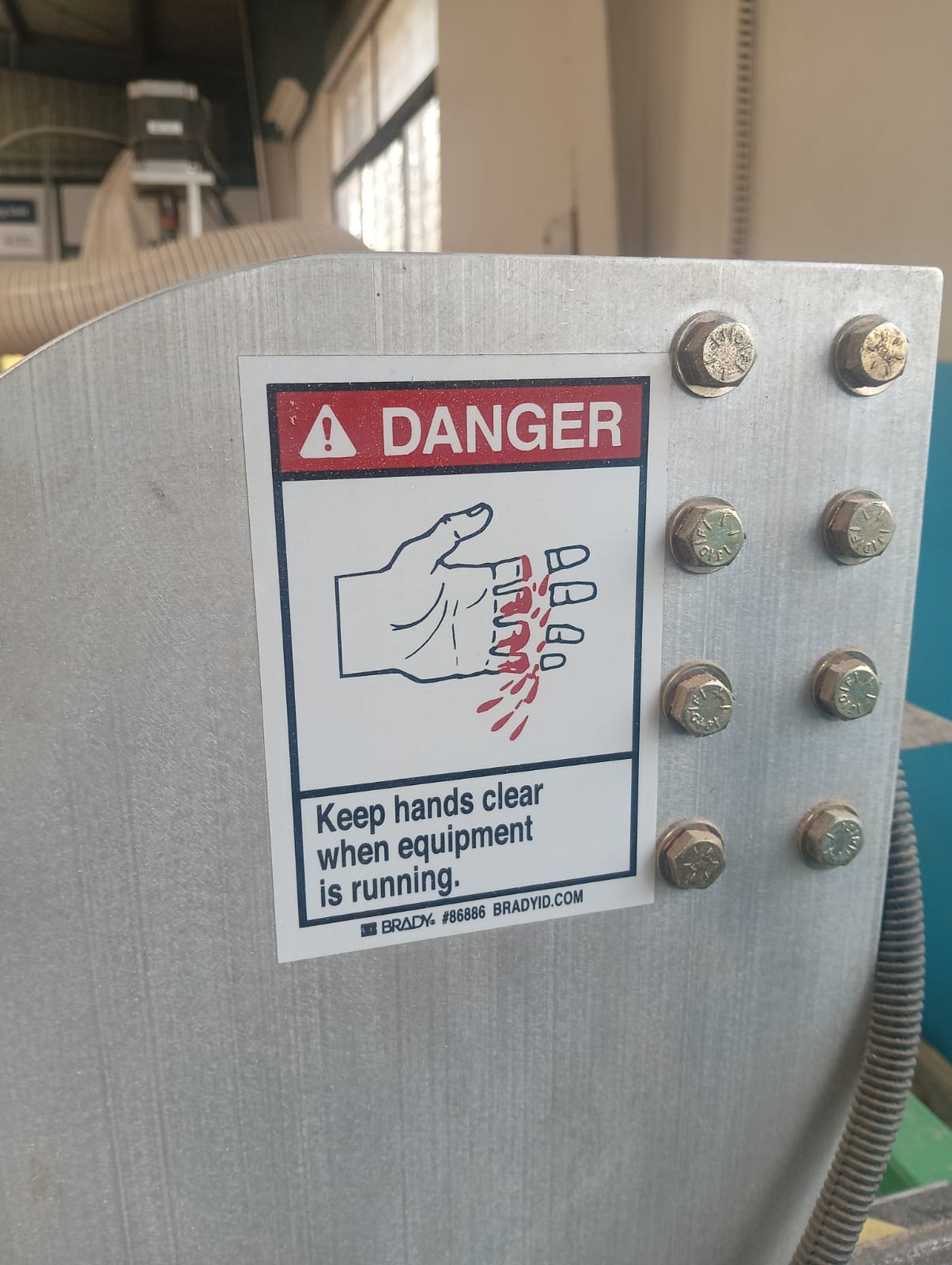
Lab Safety Requirements :
|

|
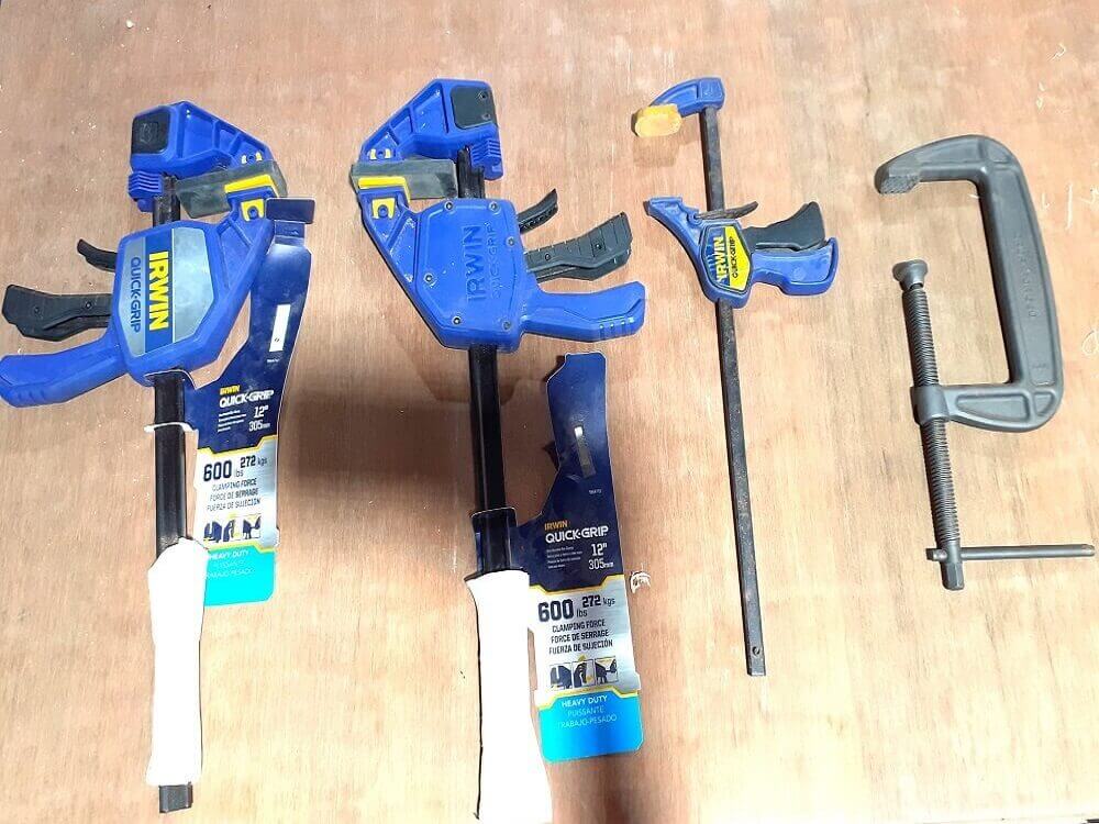
Machining Accessories and Workholding
|
|
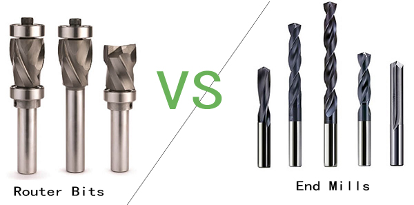
Milling Cutters vs Drilling Tools
End mills are used for cutting and shaping materials in different directions, not just straight down. Drill bits, on the other hand, are made specifically for drilling holes by moving only in a vertical direction. The key difference is that end mills can create complex shapes, while drill bits are mainly for making round holes.
Group Assignment
Objective of the Group Assignment
- Use the test equipment in your lab to observe the operation of a microcontroller circuit board
- Demonstrate the use of a multimeter and oscilloscope
- Document your work on the group work page and reflect on your individual page
Forest CNC Router:
A computer-controlled device for accurate cutting, engraving, and creating is the Forest CNC Router. It can be used on light metals, composites, wood, and plastic. Fabrication, prototyping, signage, furniture manufacturing, and industrial applications are its primary uses.
Key Features
- Accurate and clean cuts are guaranteed by precise cutting.
- Supports Multiple equipment: It is compatible with a wide range of engraving and cutting equipment.
- Computer programming is used to control automated operations.
- Supports wood, MDF, acrylic, PVC, aluminium, and other materials.
- Control the speed and feed according to the depth of cutting and the material.
- Big Workspace: Ideal for both little and major tasks.
- Safety features include a dust extraction system, spindle control, and emergency stop.
Specifications
| Category | Specification |
|---|---|
| Construction and Frame | Material: Steel or cast iron Size: Table sizes range from 2’x3’ to 5’x10’ or more |
| Spindle | Power: 2.2 kW to 12 kW Speed: 6,000 to 24,000 RPM Cooling: Air-cooled or water-cooled |
| Axes | Number of Axes: 3-axis (X, Y, Z) Movement: Ball screws or rack and pinion Resolution: Down to 0.01 mm or better |
| Controller | Type: Dedicated CNC or PC-based controllers Software Compatibility: AutoCAD, SolidWorks, VCarve, etc. User Interface: Touch screen or handheld pendant |
| Cutting Area | Dimensions: Common sizes are 4’x8’ or custom sizes Z-Axis Travel: 0 inches to 12 inches |
End Mill Flute Types & End Cut Types
| Category | Type | Description |
|---|---|---|
| Flute Types | Single Flute | Best for soft materials like plastic and aluminum; allows fast material removal. |
| Double Flute | Balances speed and finish quality; commonly used for wood and soft metals. | |
| Three Flute | Ideal for hardwoods and aluminum; provides a smooth cut. | |
| Four Flute | Provides a high-quality finish; good for metals and fine detailing. | |
| Multi-Flute (5+) | Used for high-speed finishing with superior surface quality. | |
| End Cut Types | Square End Mill | Creates sharp, straight edges; used for slotting and profiling. |
| Ball Nose End Mill | Ideal for 3D contouring, curved surfaces, and mold-making. | |
| Flat End Mill | Used for pocketing and smooth surface milling. | |
| Corner Radius End Mill | A hybrid between a square and ball nose, reducing chipping. | |
| Tapered End Mill | Used for engraving and angled machining. |
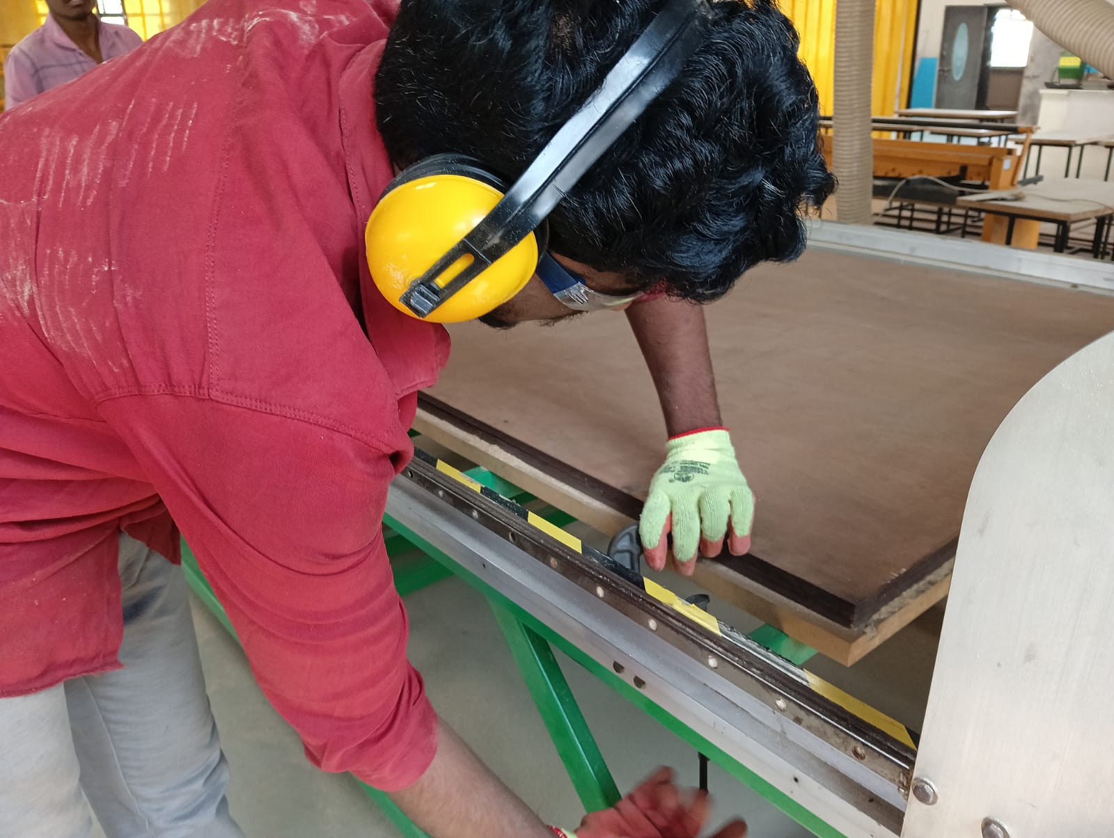
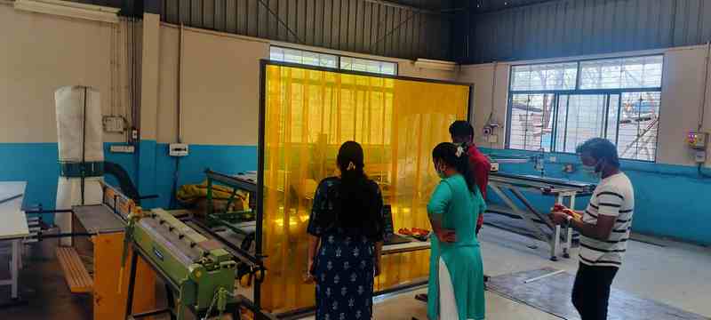
Safety Measures
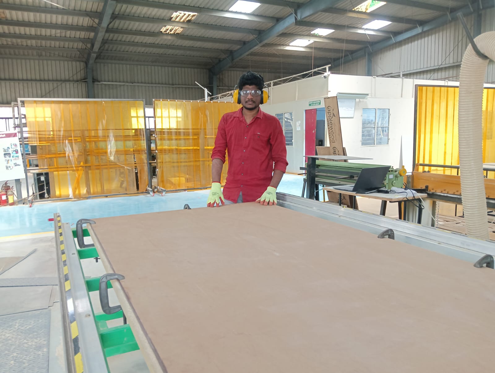
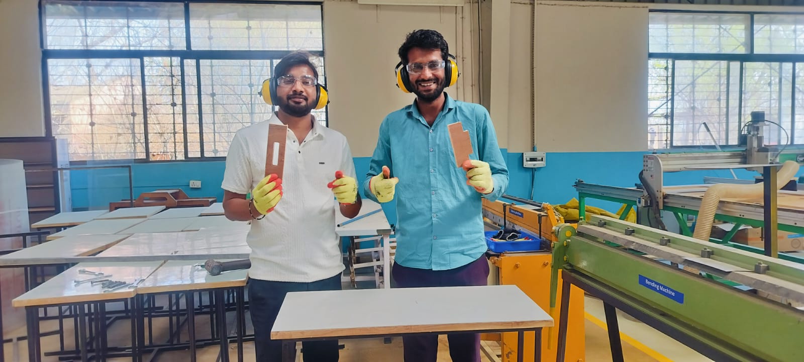
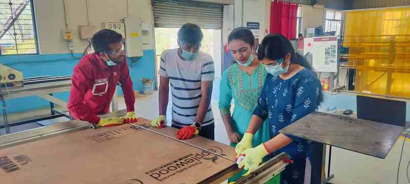
Prior to beginning the work, we carefully reviewed the safety procedures, the things we need to wear when operating the machine, and the precautions we should take.
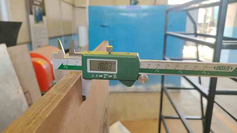
1. First, we selected plywood, which was 18mm thick.
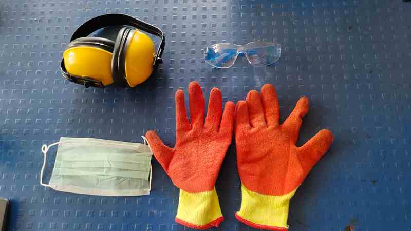
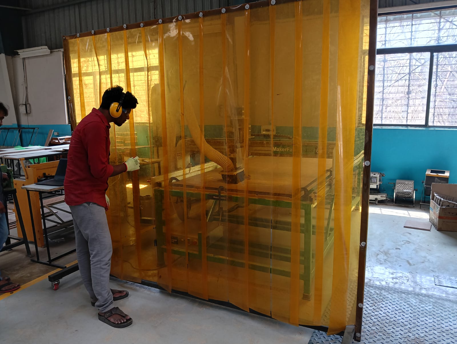
2. After that, we focused more on safety tools, using headphones, glasses, gloves, and a mask.
3.Then, we thoroughly cleaned the machine.
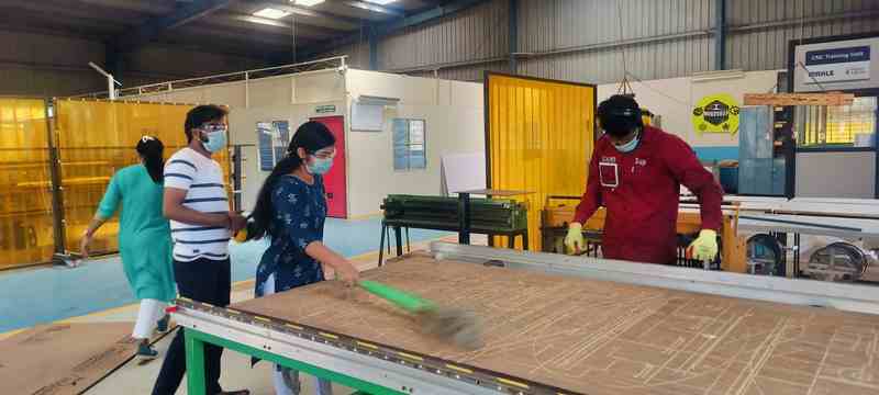
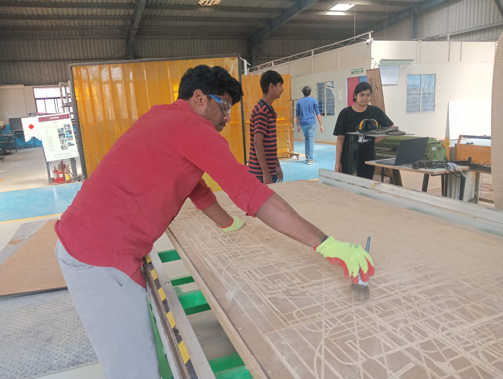
4. Useing CNC machine safety shield
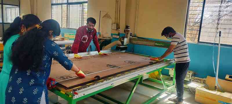
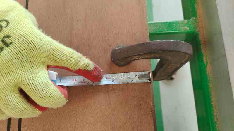
5.Then, we measured the horizontal dimensions of the plywood.
6. Then, we measured the vertical dimensions of the plywood
Toolpath & Cutting Parameters
Different toolpaths include pocketing, profiling, and engraving. Parameters such as feed rate, spindle speed, and depth of cut impact the quality of the machining.
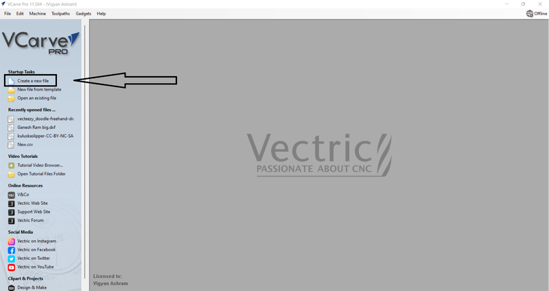
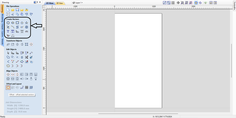
1. First, we gathered basic information about the V Curve Pro software on the laptop at the Vigyan Ashram and then opened the software. After that, we clicked on "Create a New File.
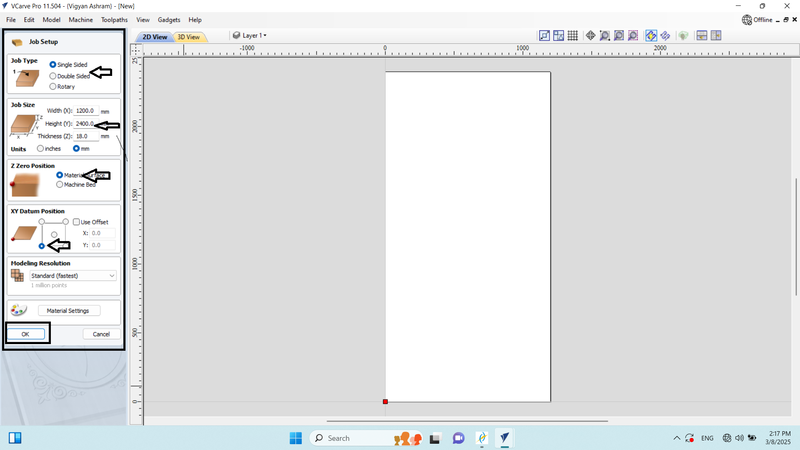
2. After creating the file, we set up the job.
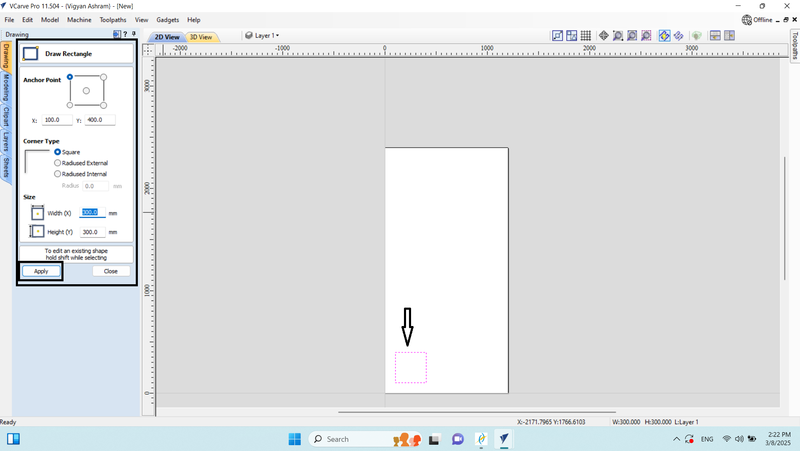
3. On the drawing page, we gained basic information about vector design and then created a rectangle.
4. After that, we set the rectangle's size to a width and height of 300 by 300 mm and applied the changes.
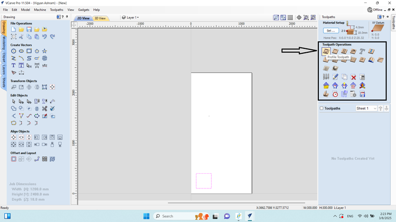
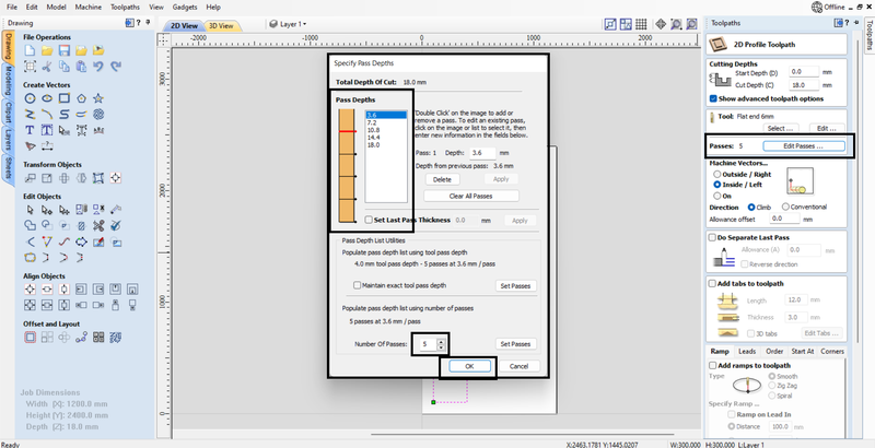
5. We selected the Profile Tool Path and learned about the tool path operations.
6. We selected a 6 mm end mill for the tool path and gathered information about the tool and its flat.
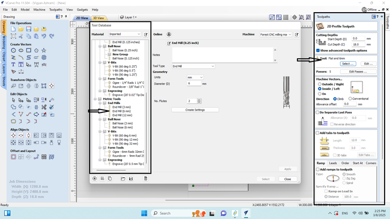
7. To edit the passes, we set the pass depth to 3.6 mm, which resulted in 5 passes, allowing us to cut through the 18 mm plywood in 5 passes.
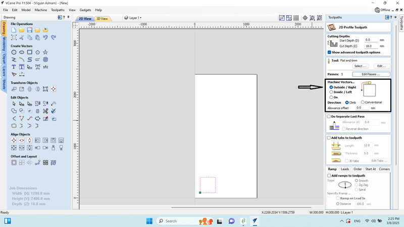
8. In the machine vector, we set it to "Outside/Right" because we needed to start the cutting from the outer side of the design at 300 mm. Next, we entered the tool path name and clicked on "Calculate."

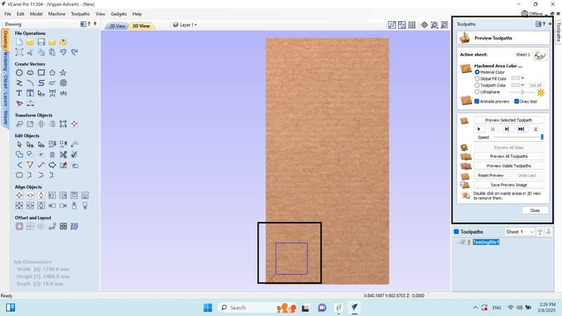
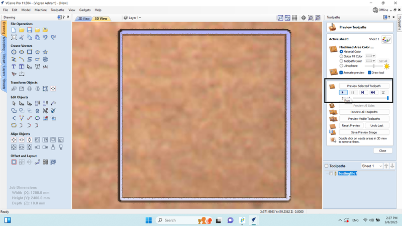
9. We run the preview of the selected tool path, where we saw that our design was cut in 5 passes, and then we closed it.
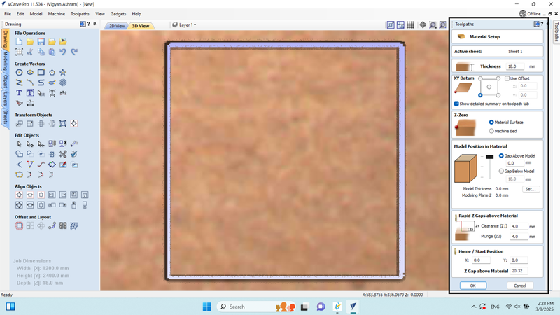
10. In the material setup, we configured the material settings.
11. In the tool path section, we saved the tool path in (.CNC) file format, which generated our G-code.
12. Saved the G-code in .cnc file format on the local device.
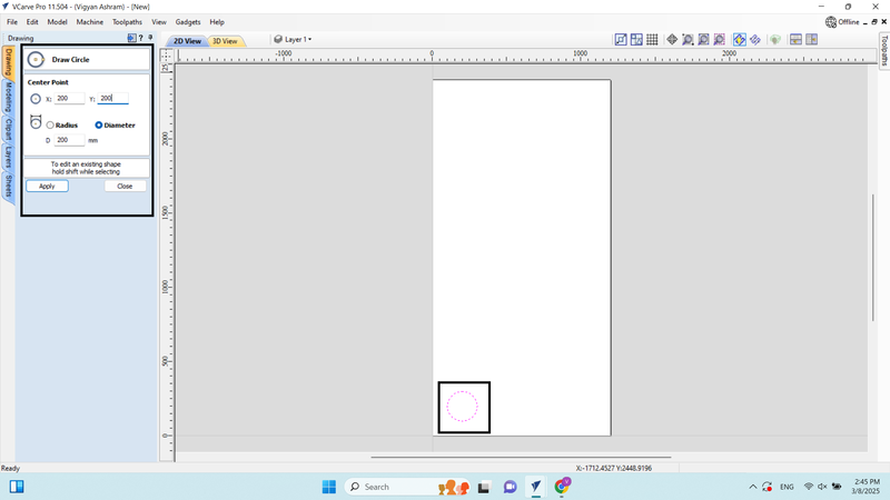
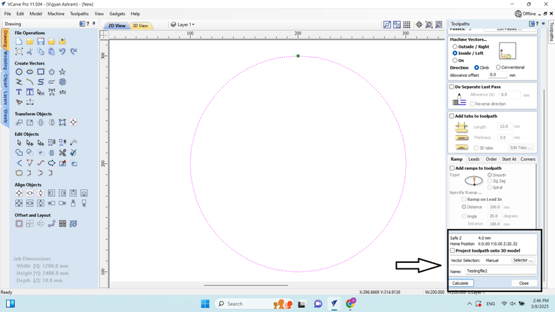
13. This time, we drew a circle in the drawing workspace with a diameter of 200.
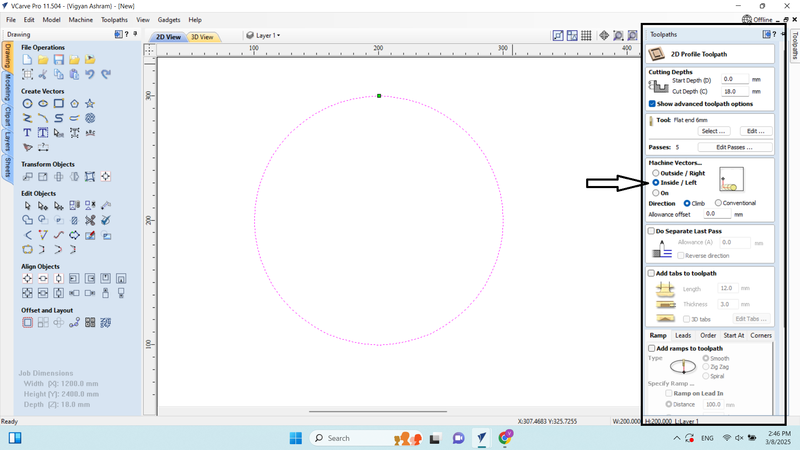
14. In the 2D profile tool path, we adjusted the settings according to the material and set the machine vector to "Inside (Slice)/Left" because this time we wanted the end mill to cut from the inside.
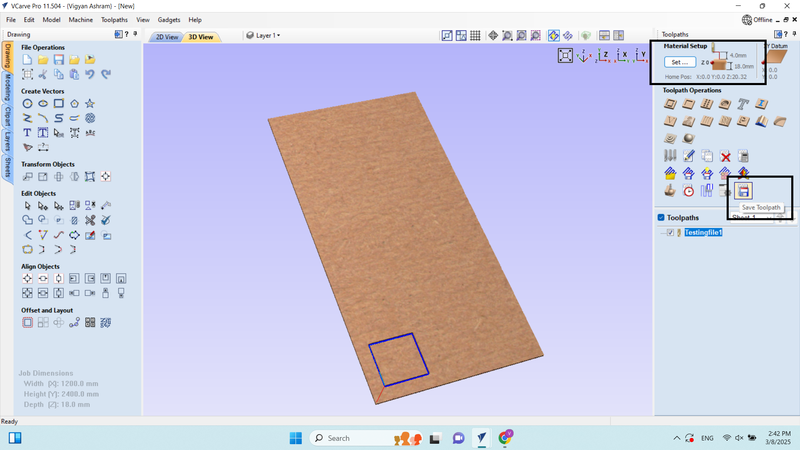
15.We entered into the tool path option and saved the tool path.
16. Saved the G-code in .cnc file format on the local device.
Individual Assignment
Objective of the Individual Assignment:
- Use an EDA tool to design a development board
- Ensure the design uses parts from the inventory to interact and communicate with an embedded microcontroller
For this individual assignment, I started thinking about what I should design and what requirements exist in my lab. During this process, I identified a problem—there is no dedicated table for placing the laptop while operating the CNC router. To solve this issue, I began brainstorming a suitable design and started creating it using SolidWorks.
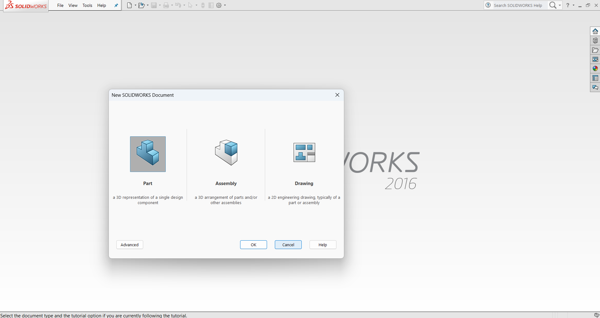
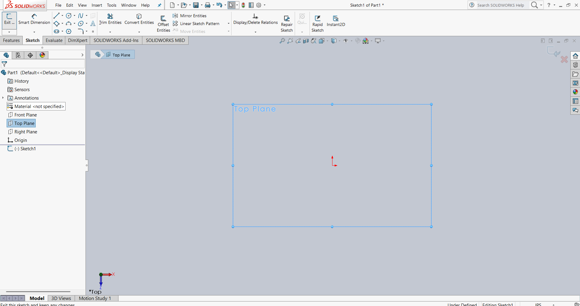
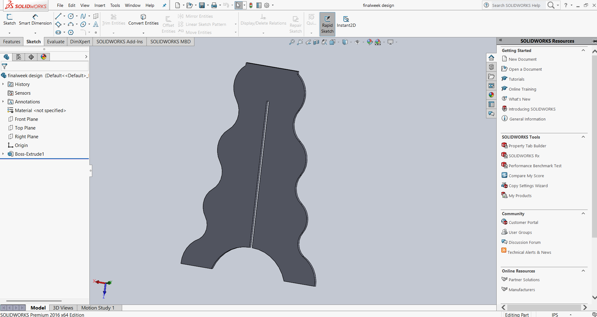
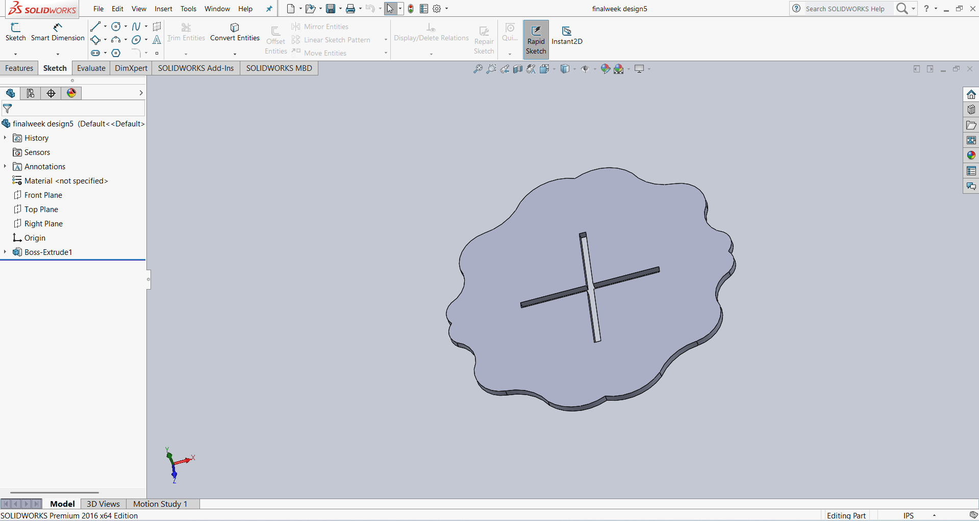
First, I created a sketch and selected the Top View in SolidWorks. Then, I began designing the table, considering the required dimensions and functionality.
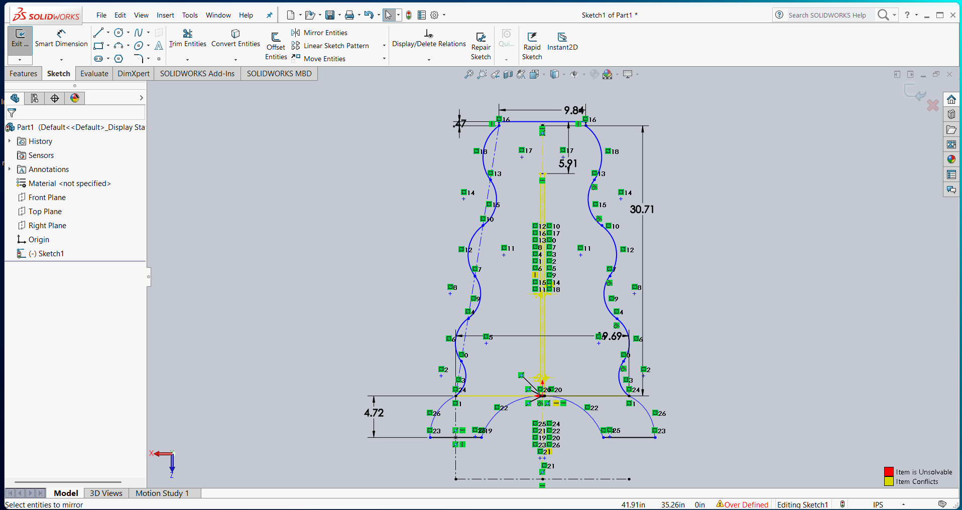
Below, I am presenting the first part of my design, including all dimensions and a 3D view of the model.
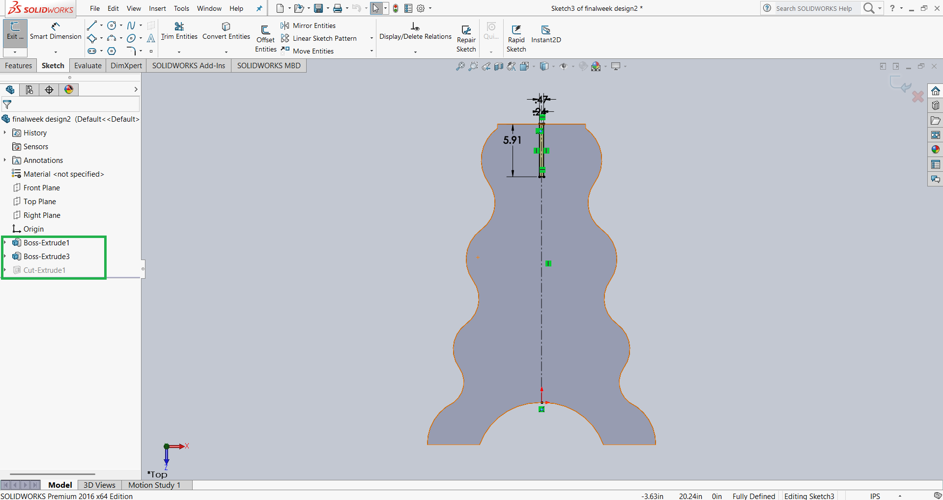
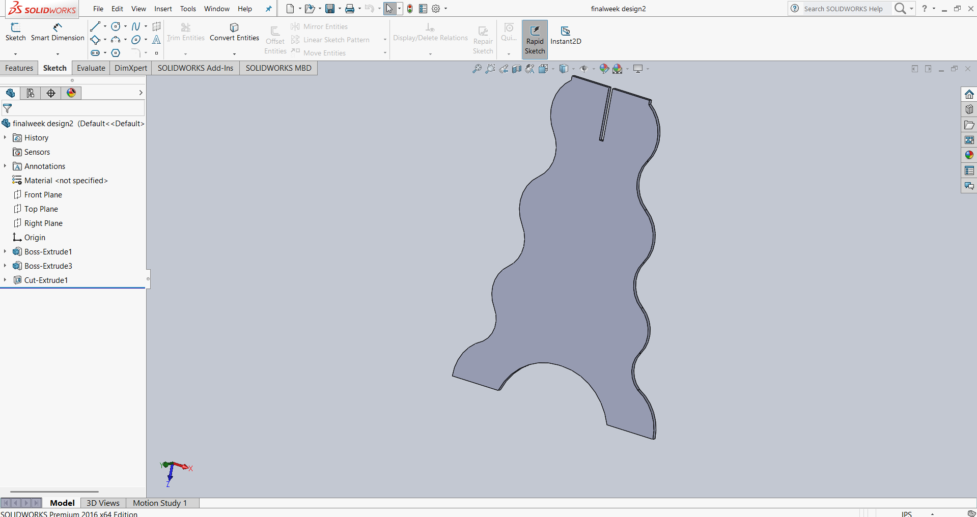
For the second part, I didn’t put much effort into redesigning it from scratch. Instead, I modified the first part by extruding the necessary sections to make them solid and using the **Extrude Cut** feature to create slots where required. Below, I am presenting the updated design with the necessary modifications.
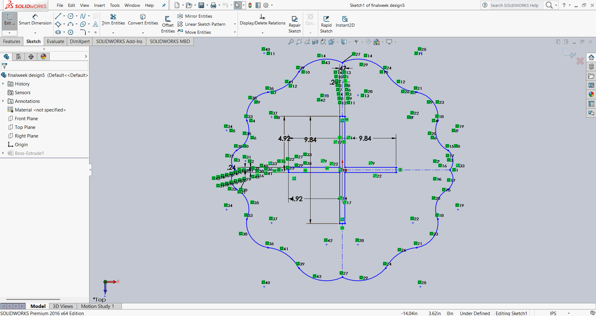
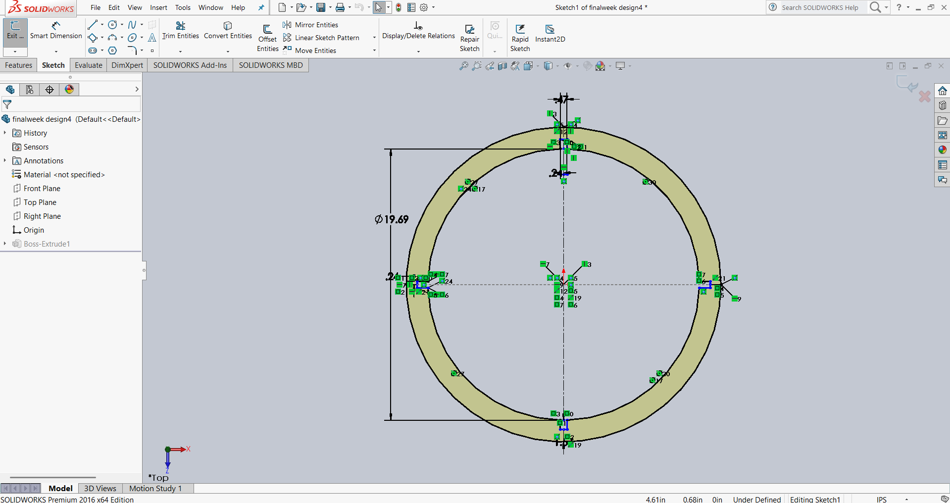
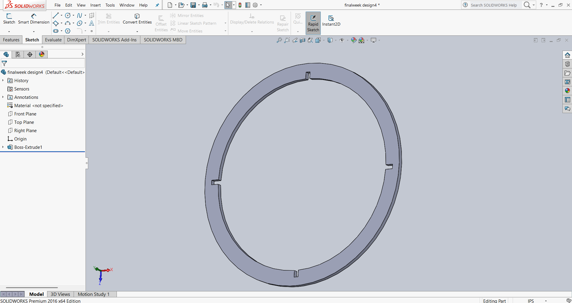
Up to this point, I have completed the **base of my table**. Next, I started thinking about the **top plate** for the table and began designing it. Below, I am presenting the dimensions and a 3D view of my design.
Then, I started thinking about the support structure and designed it to ensure the table stands more stable and sturdy. Below, I am presenting the dimensions and a 3D view of my design.
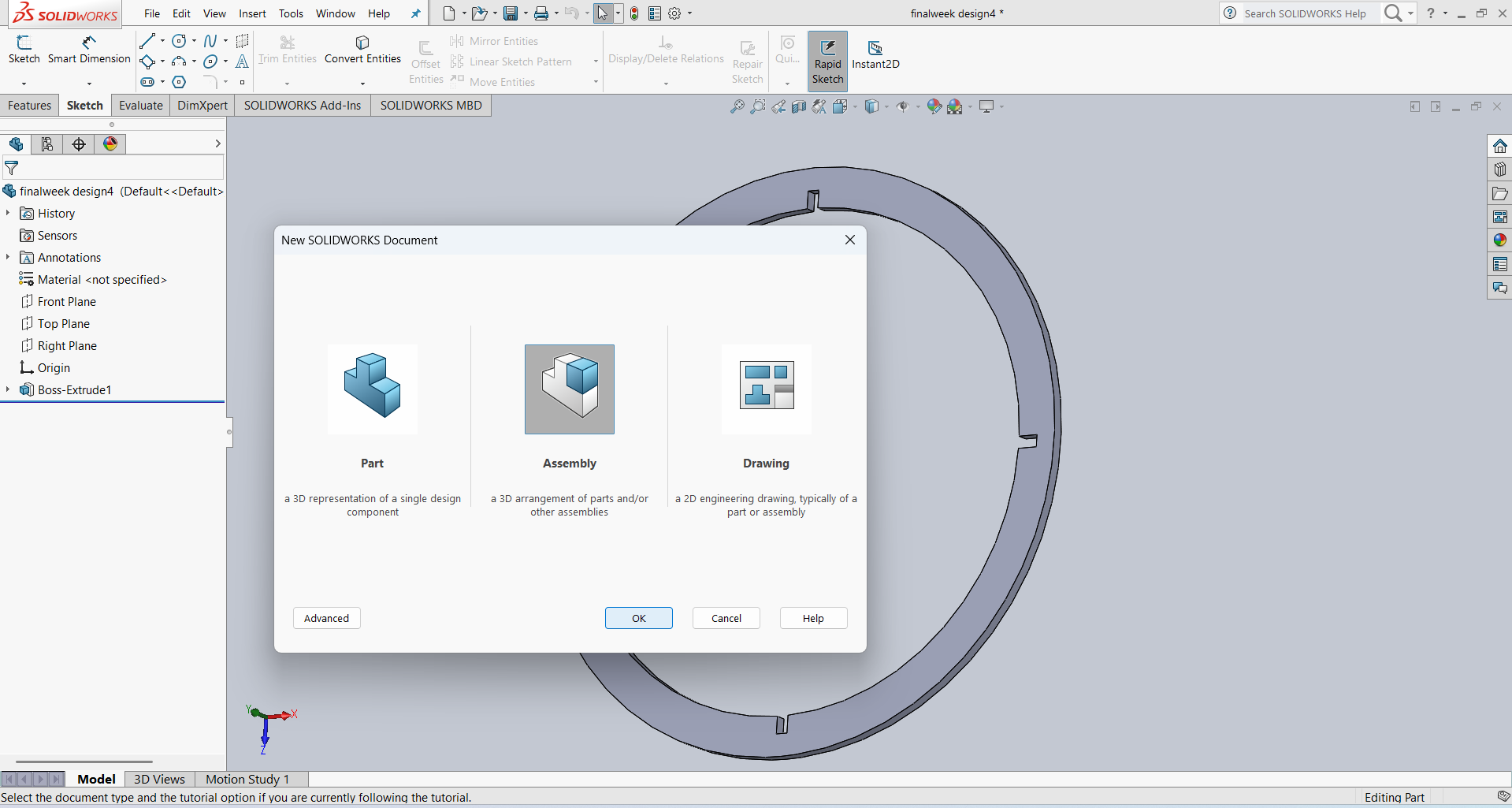
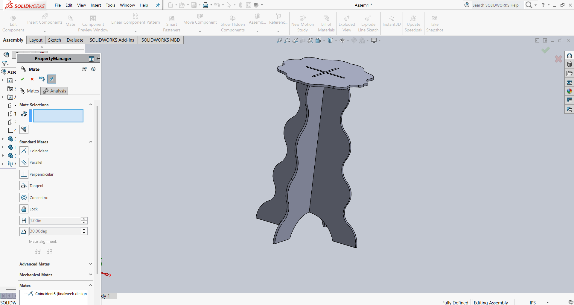
After completing the design of all the parts, I proceeded to the **assembly stage** to check whether they fit together correctly. For this, I opened a **new assembly file** in SolidWorks, inserted the parts one by one, selected **Assembly Mode**, and started assembling the components step by step.
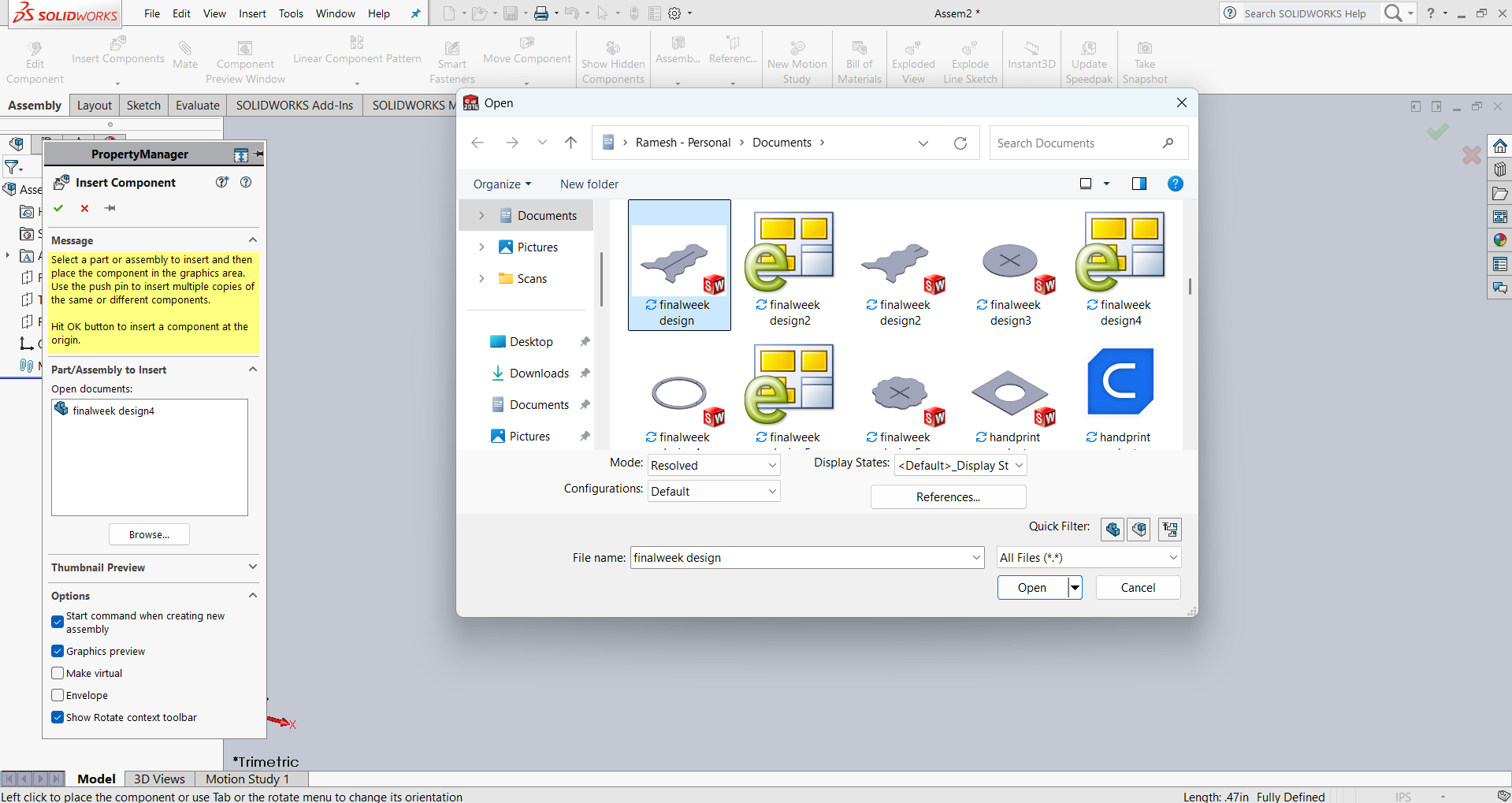
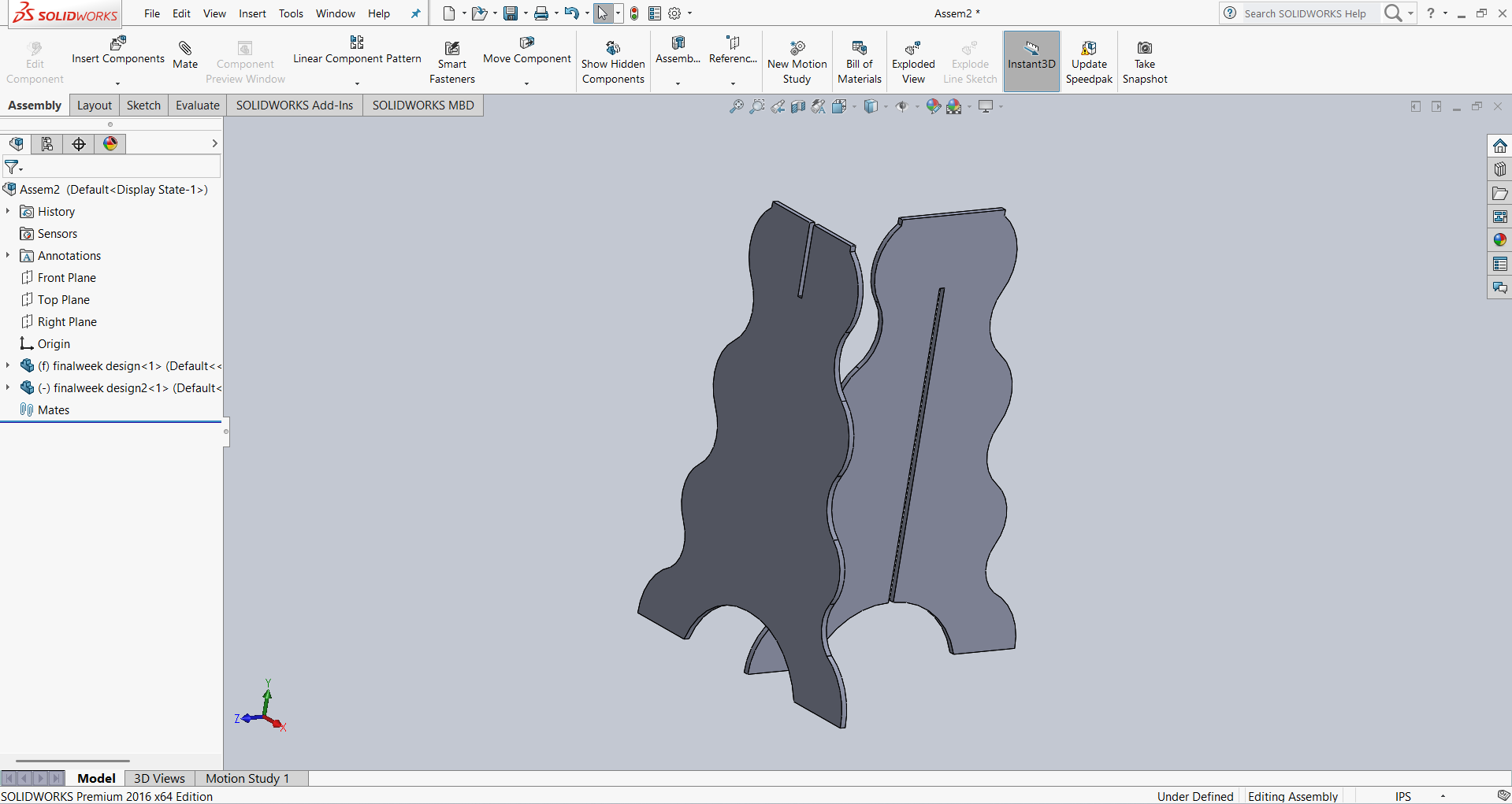
First, I imported Part 1 and Part 2 into my assembly and checked whether they were perfectly assembled. Below, I am presenting the images showing the assembly process.
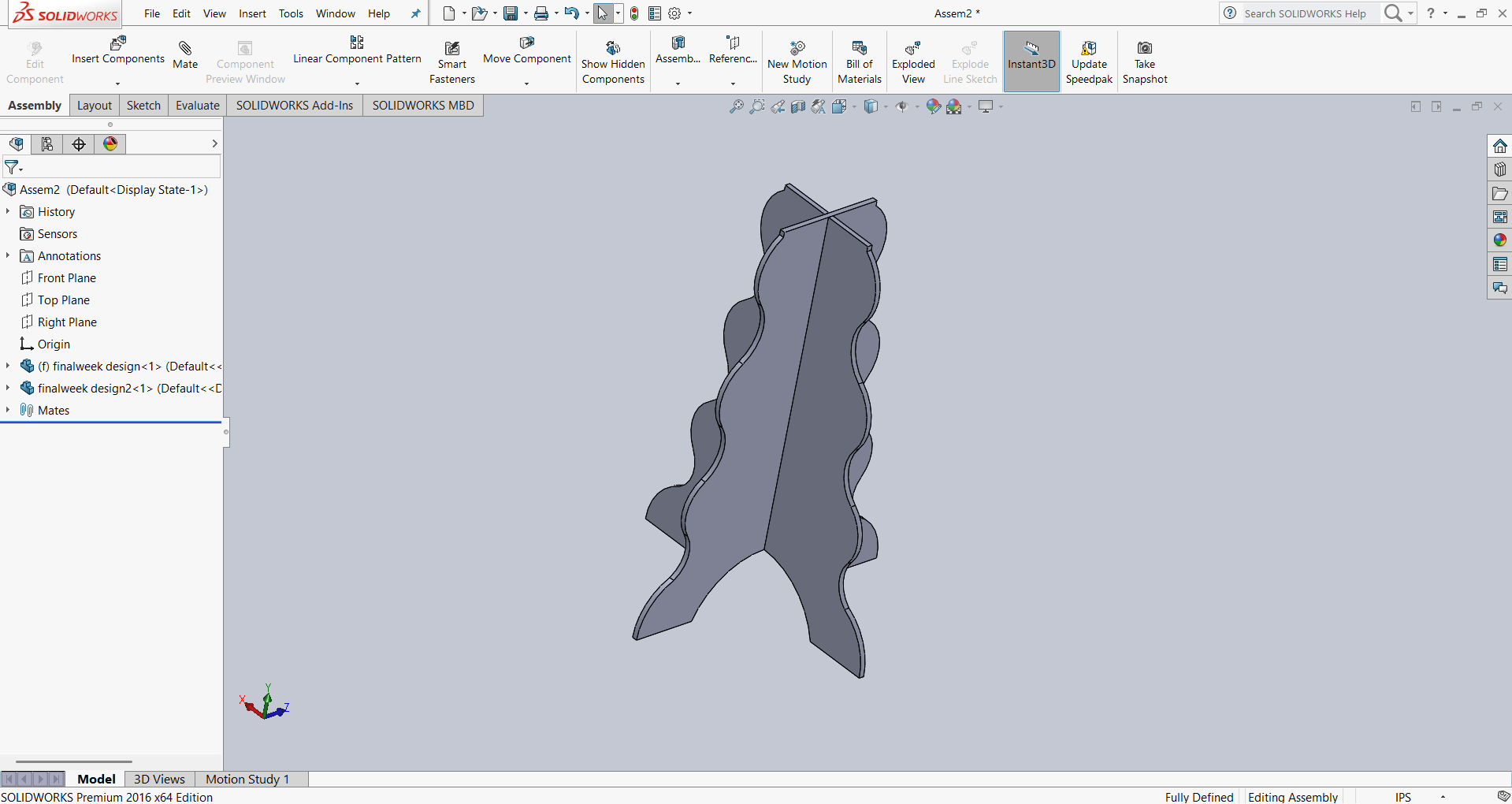
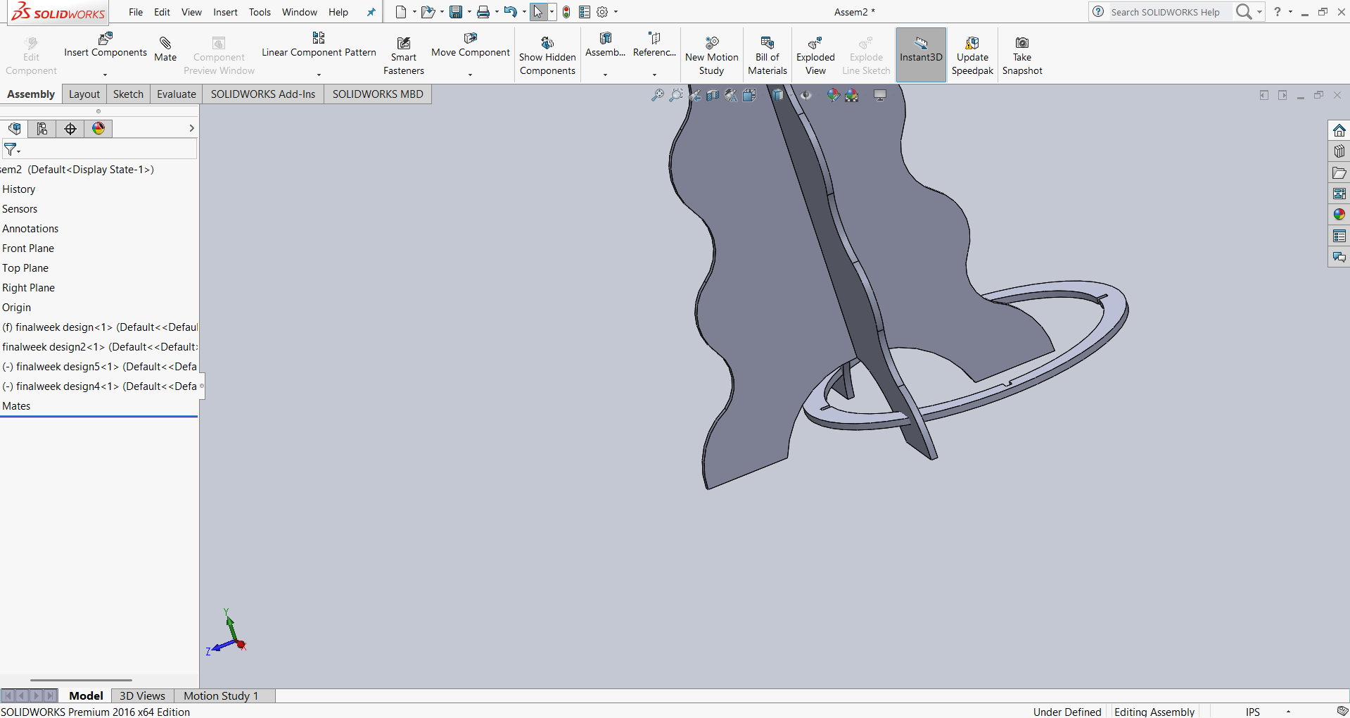
After confirming that both parts had the correct dimensions, I imported the top plate of my design and successfully assembled it. Below, I am presenting the images showing the assembly process.
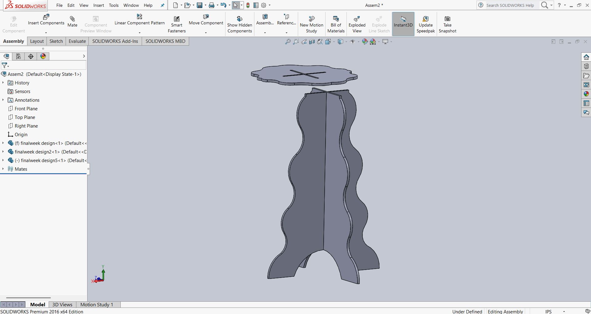
Now, I inserted the support part into my assembly and successfully assembled it, as shown in the image below.
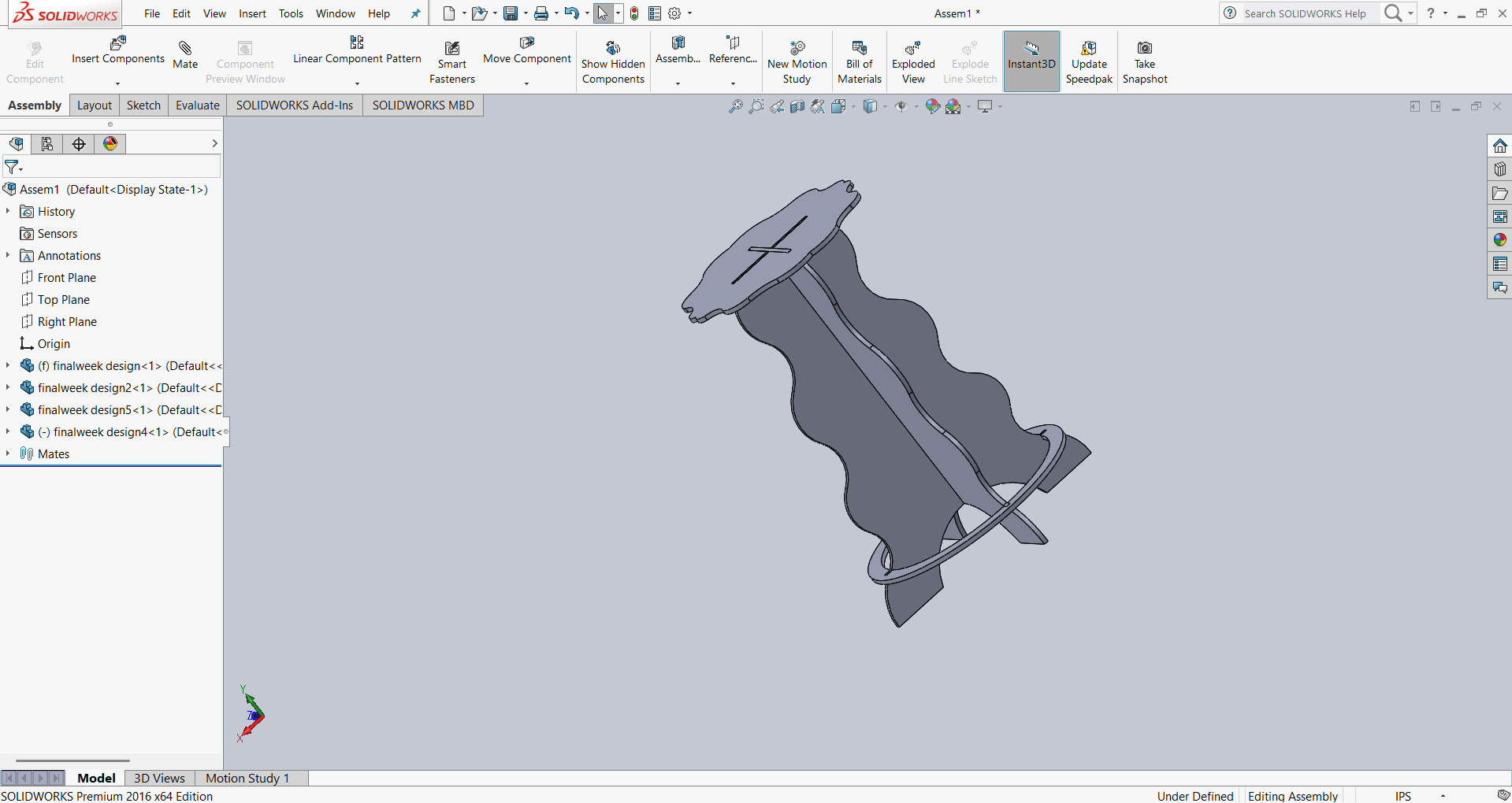
Now, I am presenting the final assembly of my design, as shown in the image below.
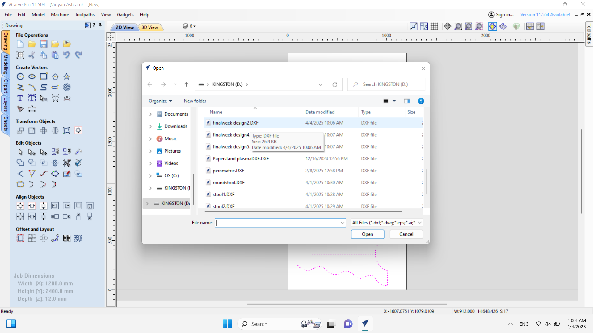
After completing the final assembly, I confirmed that my design was correct. Next, I proceeded to cut my design using a CNC router. Before machining, I saved all my design files in DXF format. Then, I converted my design into G-code using VCarve Pro 11.504. Below, I explain the process in detail.
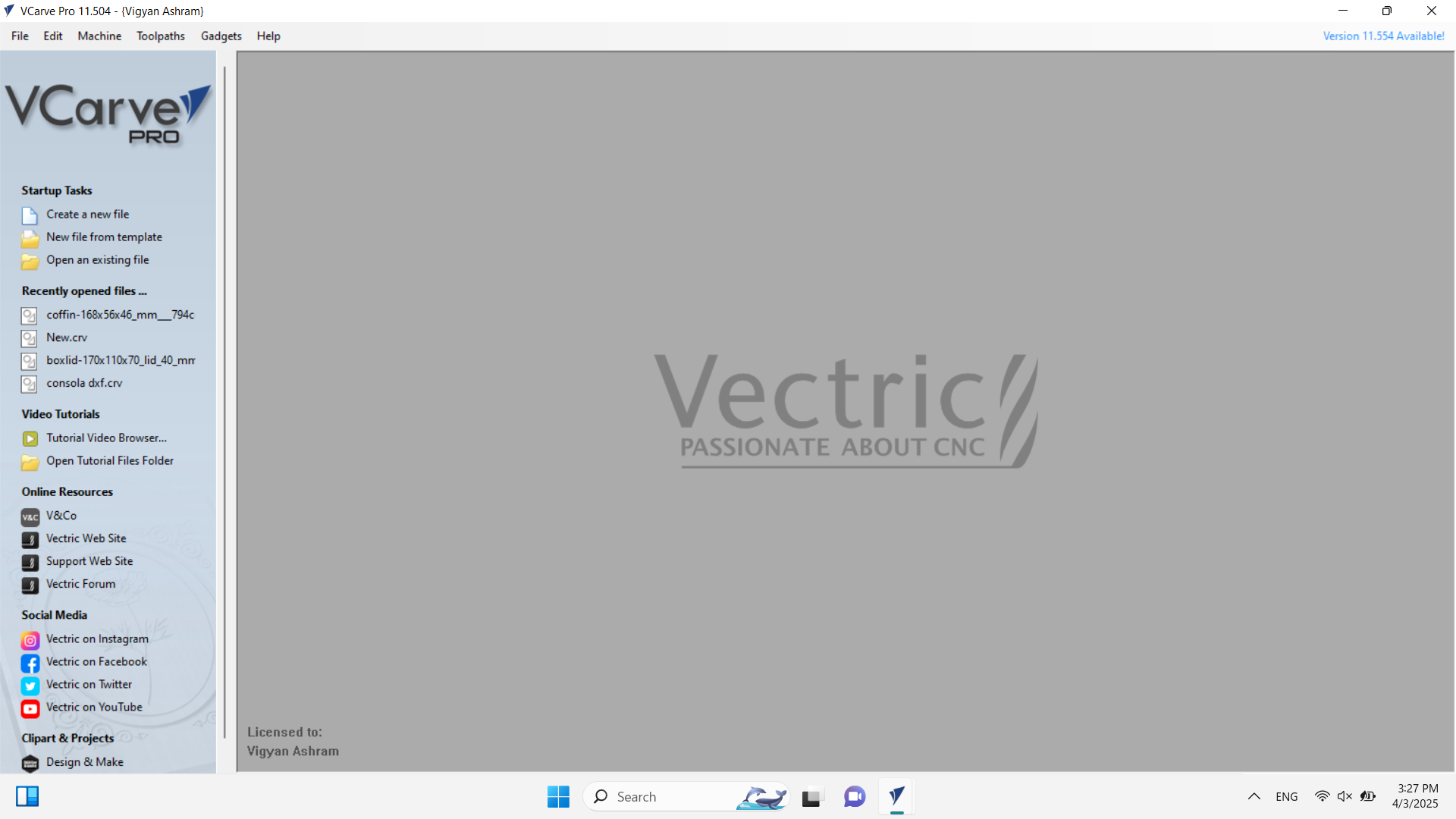
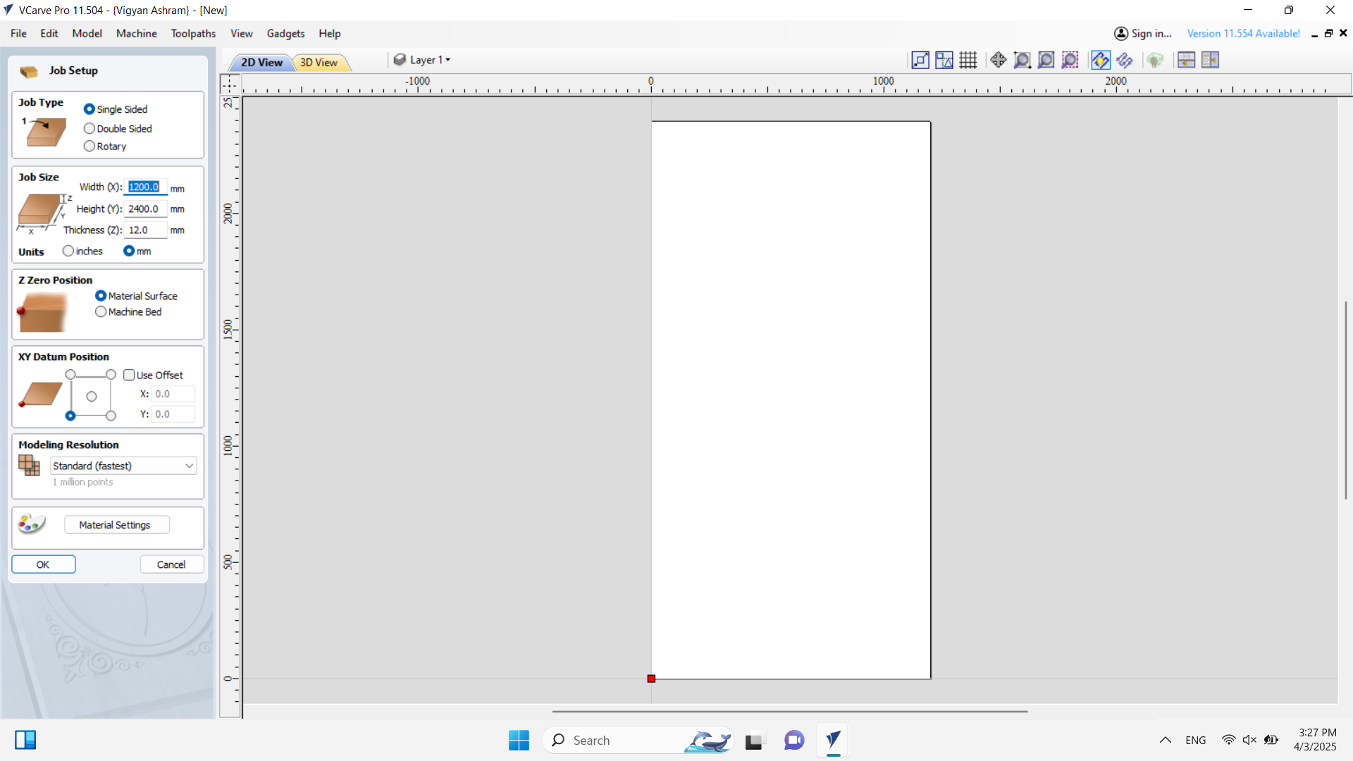
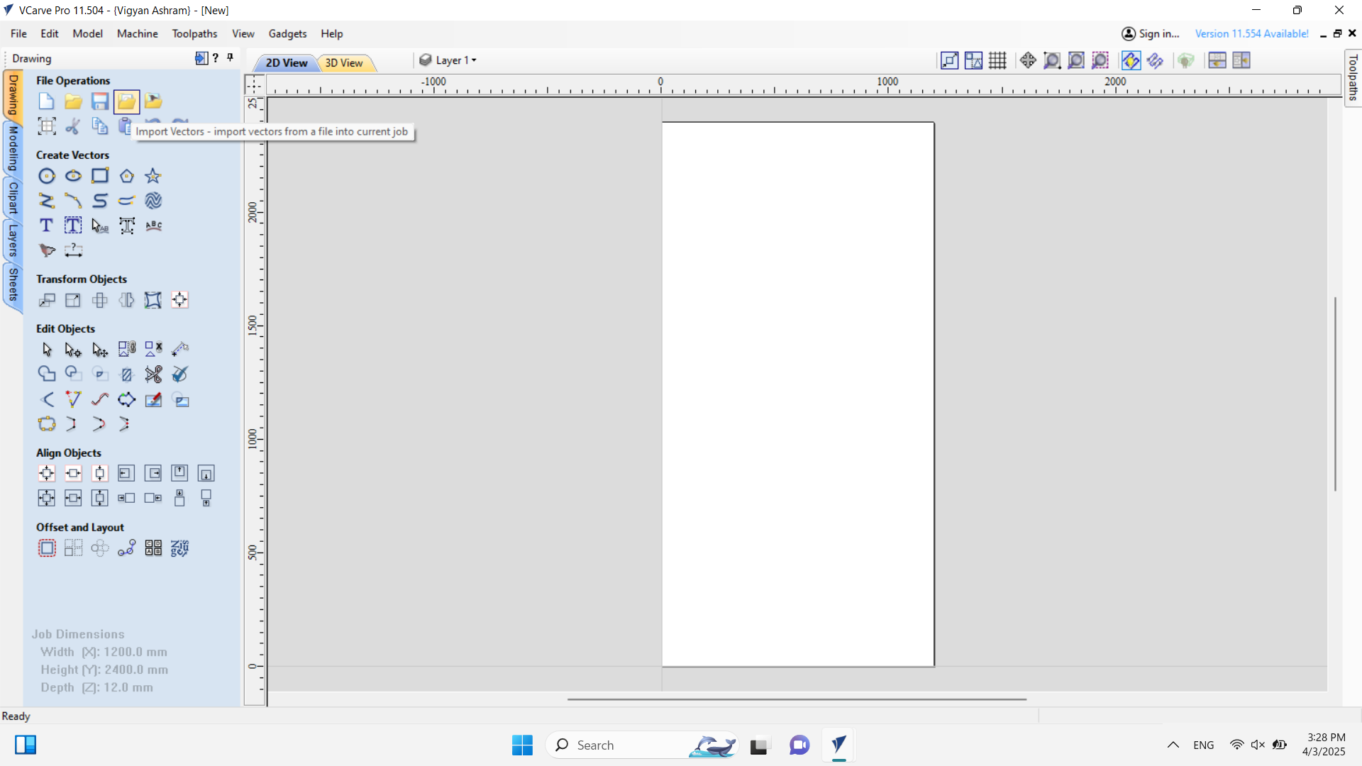
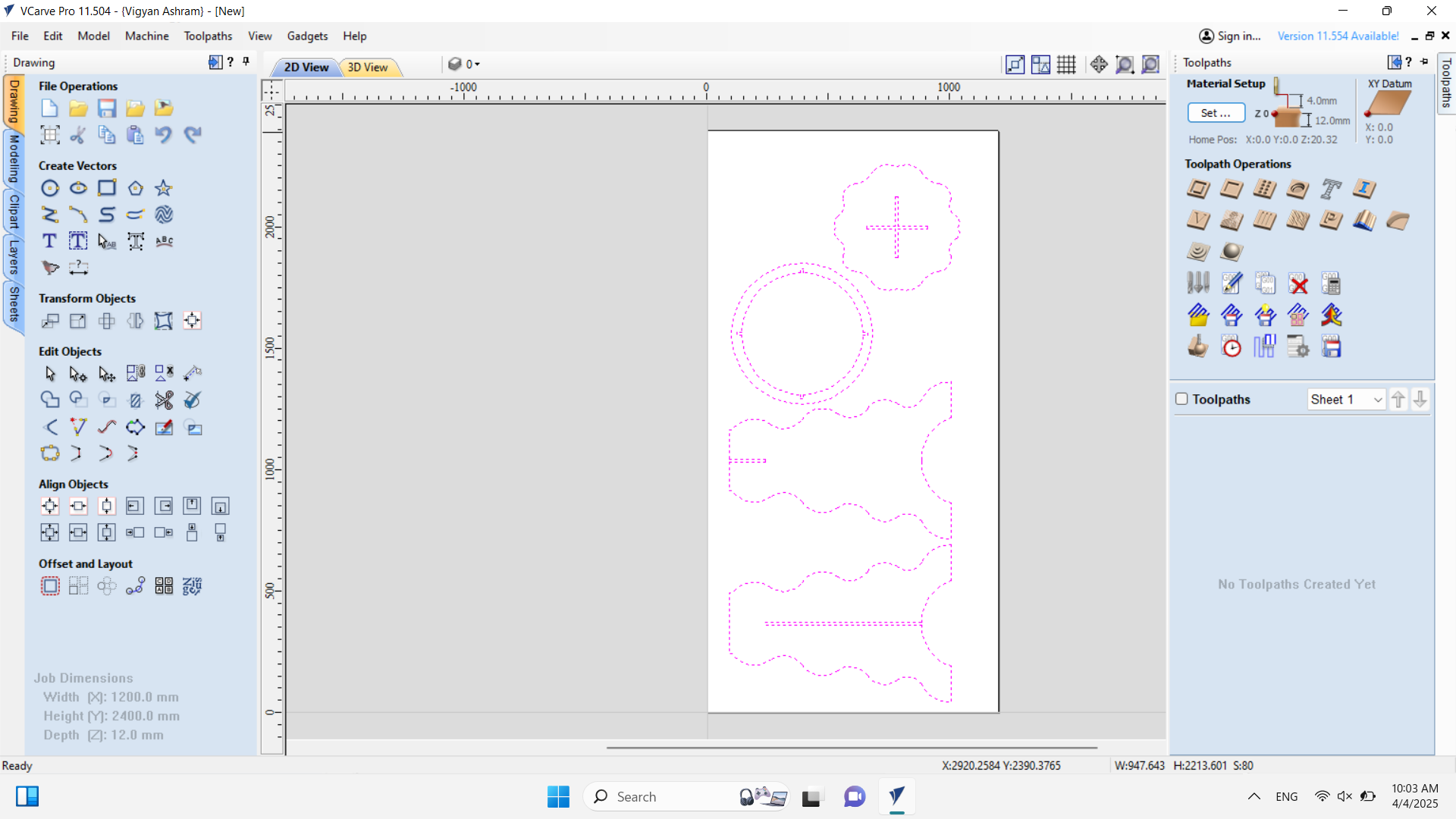
After opening VCarve Pro, I set the sheet dimensions and thickness of the material. In my case, I am using a 12mm wood sheet. I also defined the starting point of the machine, as shown in the image above. After that, I started importing the design files into the workspace.
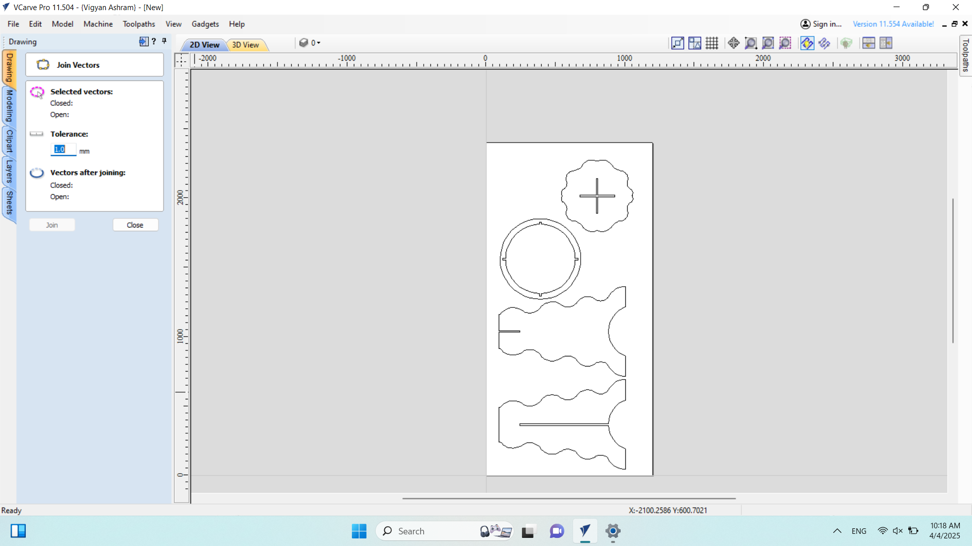
After importing all the parts into the workspace, I selected all of them and used the "Close Open Vectors" tool to ensure that all vectors were properly closed, as shown in the image below.
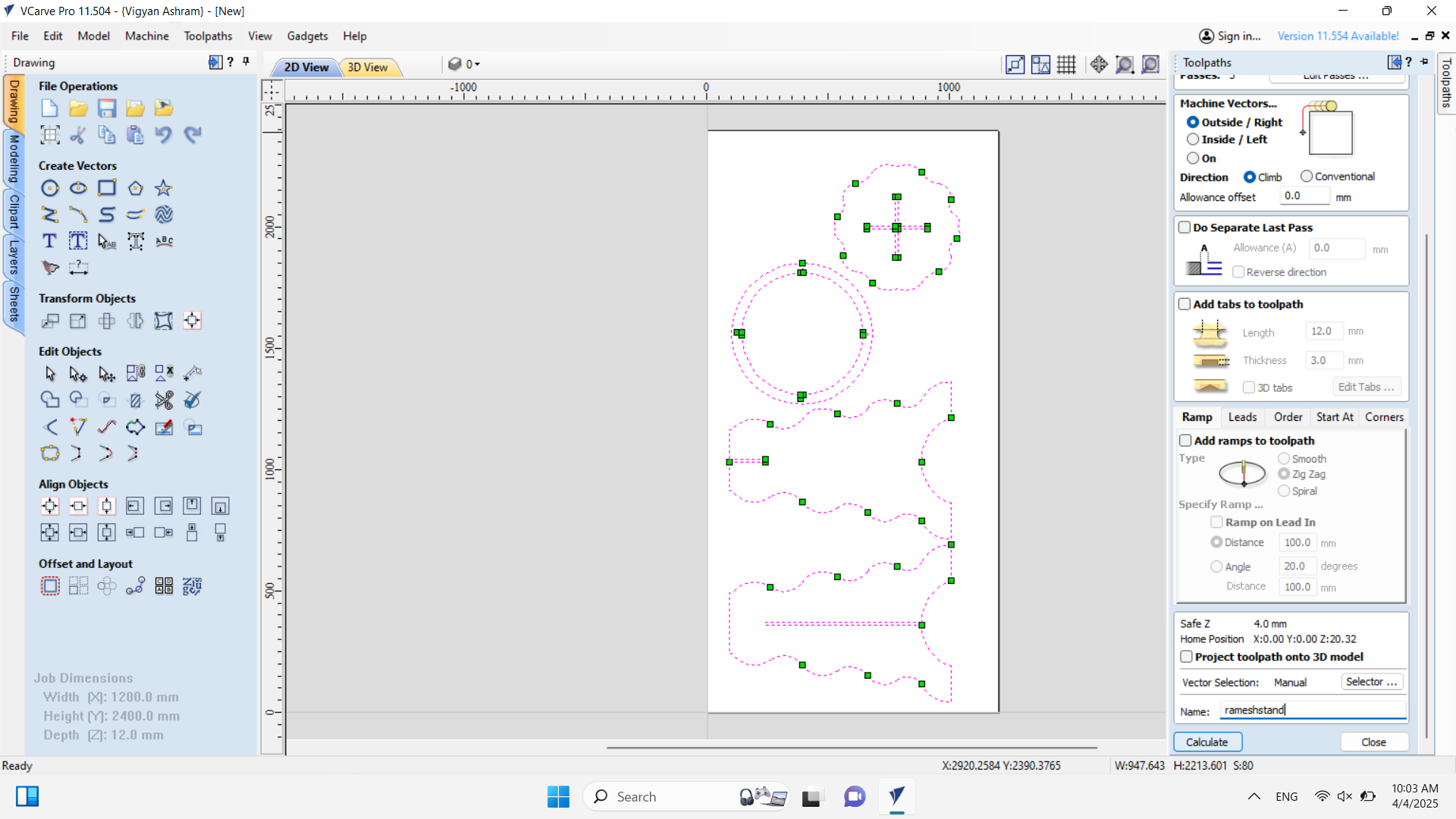
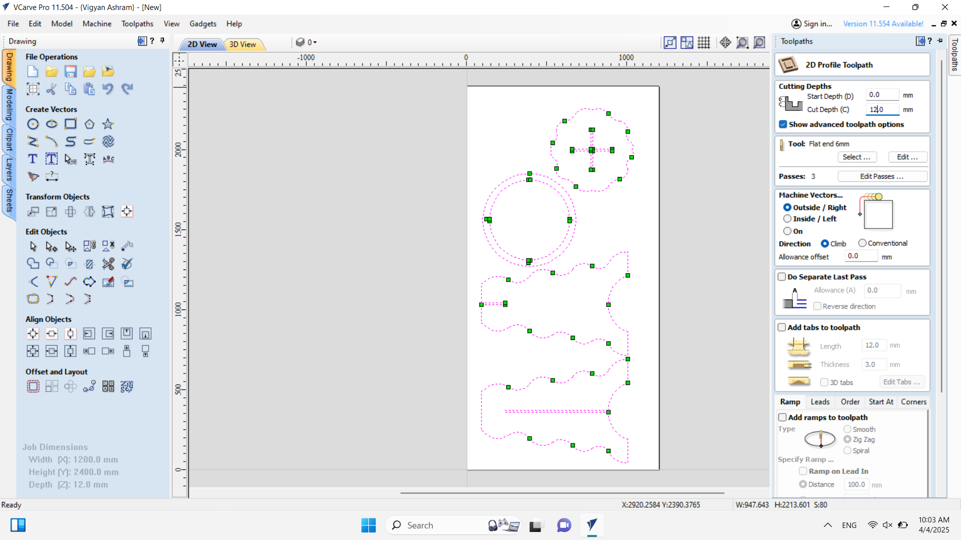
All vectors were successfully closed. Then, I proceeded to the Toolpath section, where I set the cut depth to 12 mm and adjusted all the necessary properties according to my requirements, as shown in the image below.
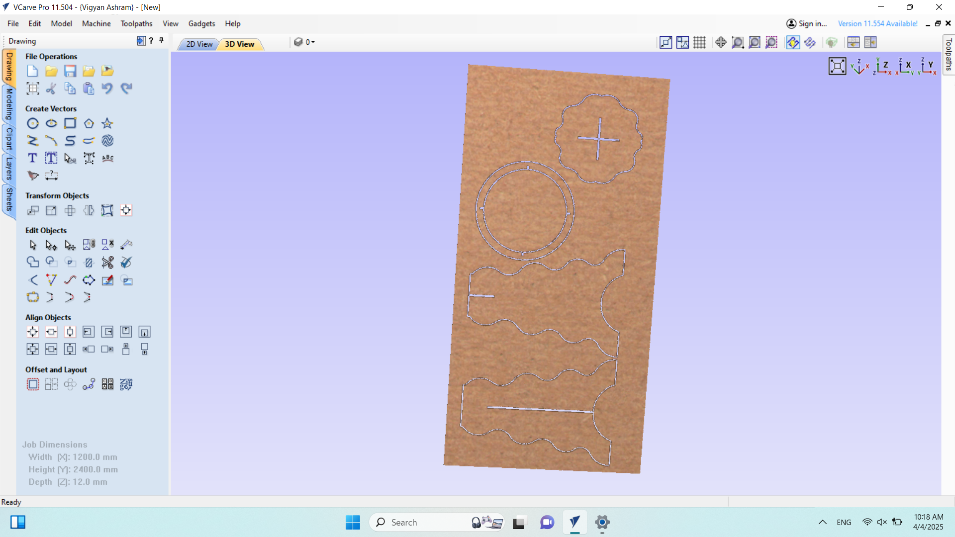
Then, I saved my file, and the **final view of the cutting path** is shown in the image below.

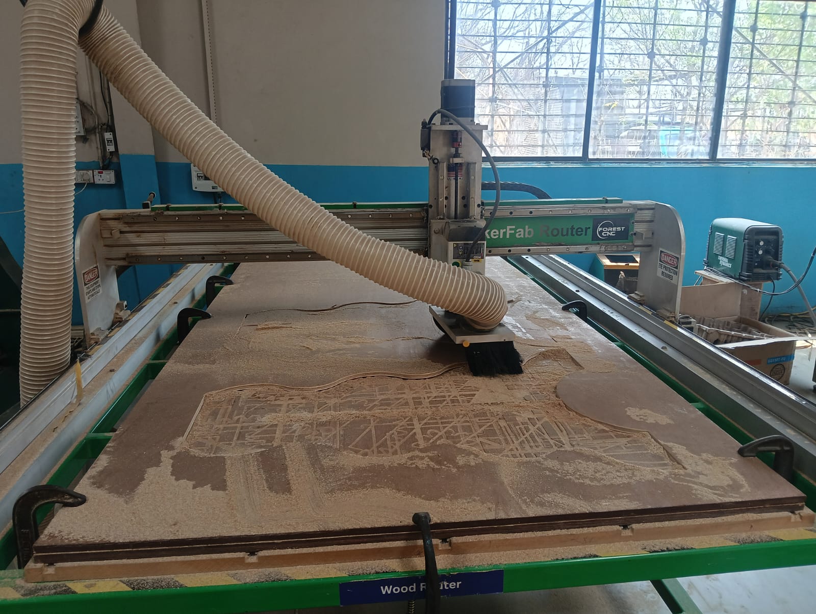
Now, I started cutting my design. Before beginning, I wore all the necessary safety gear and took proper precautions. First, I cleaned the machine to ensure smooth operation and avoid any interference during the cutting process.
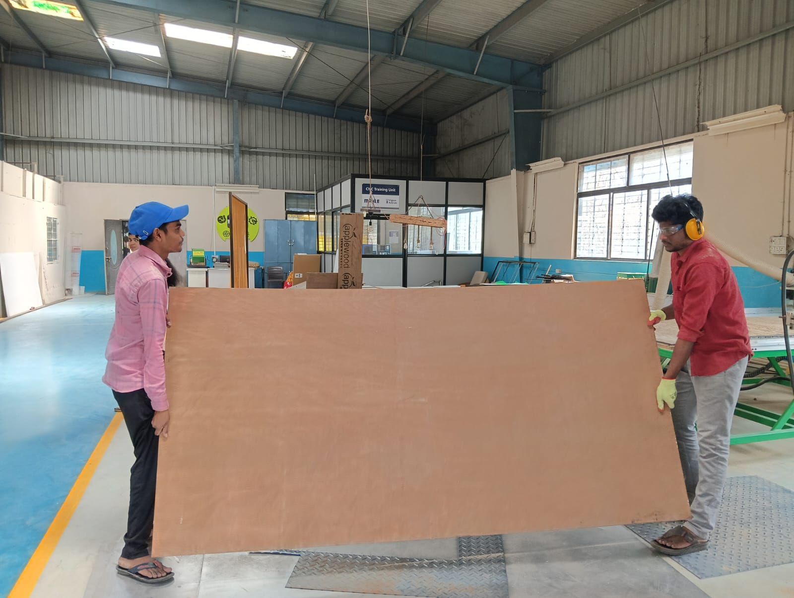
After completing the preparations, I selected the required sheet for my design. With the help of my friend, I placed it on the CNC machine, ensuring proper alignment and stability.
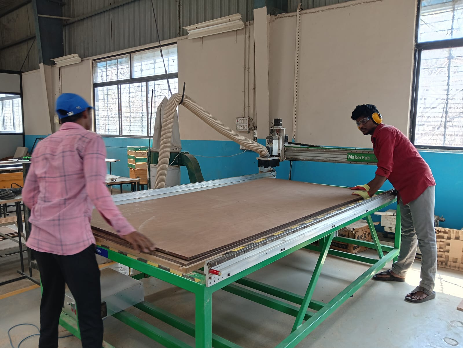
Then, I secured the wood sheet using holding tools to ensure it remained stable and did not move during the cutting process. Proper alignment was carefully maintained to achieve accurate results.
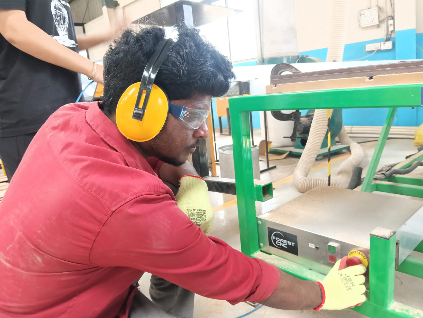
After properly **securing the sheet**, I **turned on the power supply** to start the CNC machine. Below
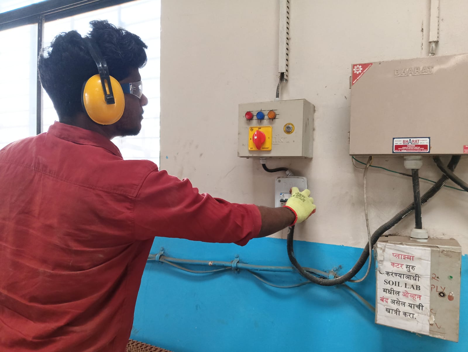
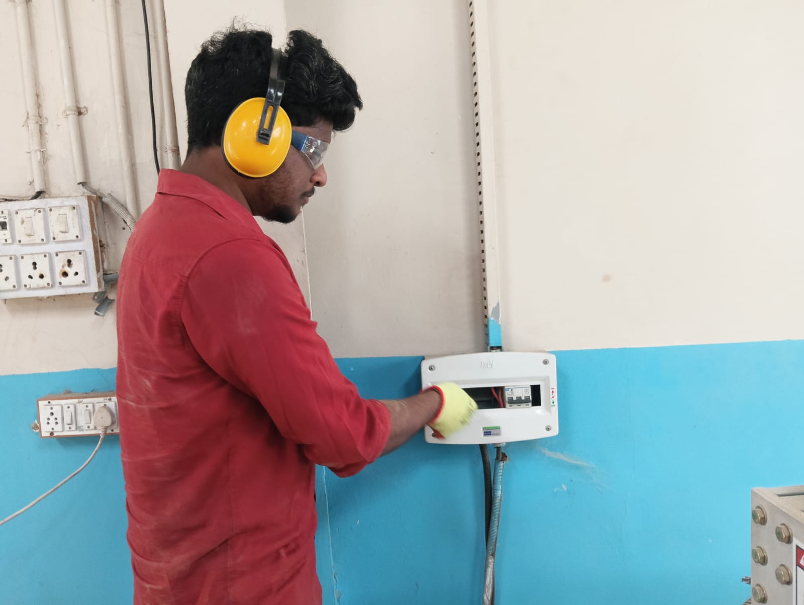
After turning on the **power supply**, I **switched on the machine** by **releasing the emergency button** and proceeded with the cutting process.
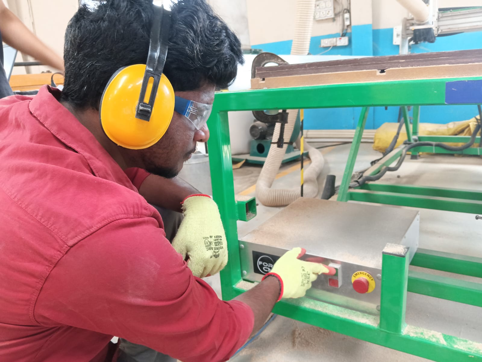
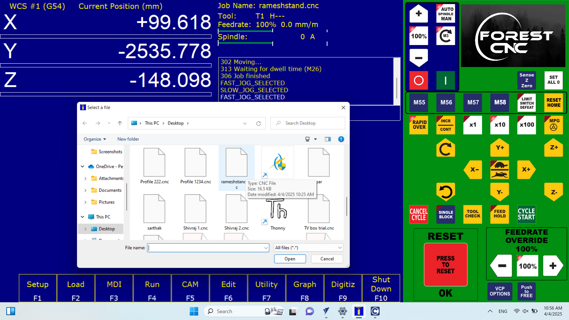
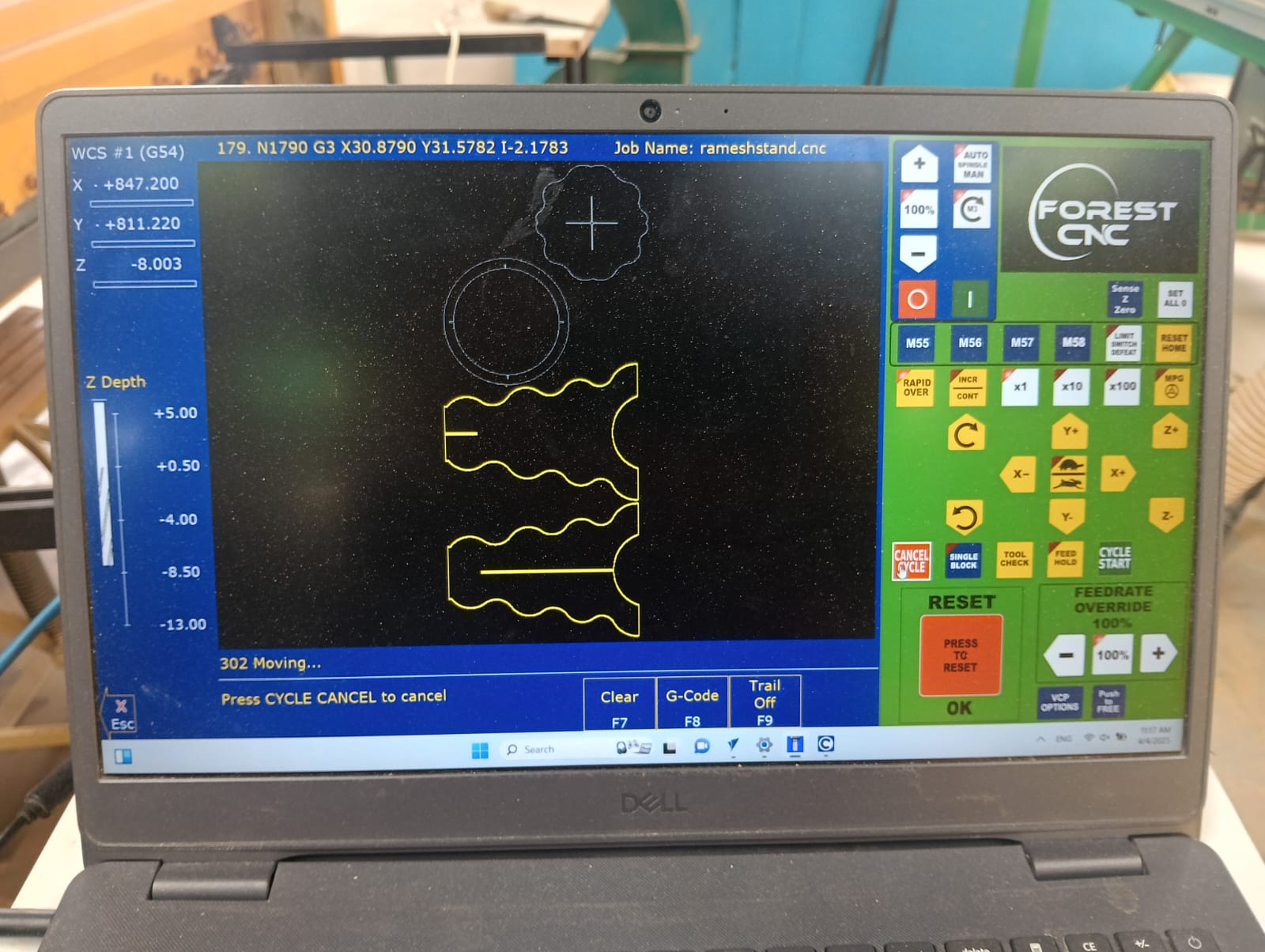
After that, I opened my laptop and launched the Forest CNC software. I then set all axes to zero and moved the machine to its starting position to begin the cutting process.
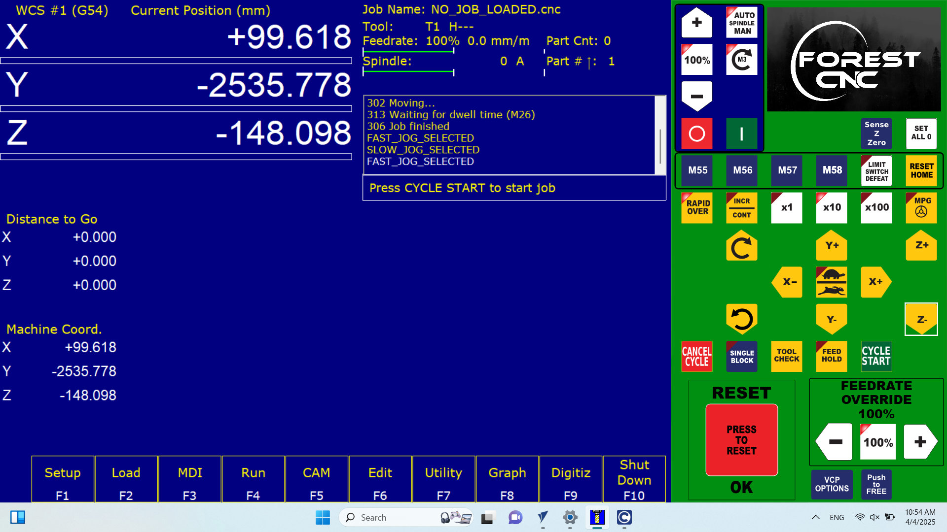
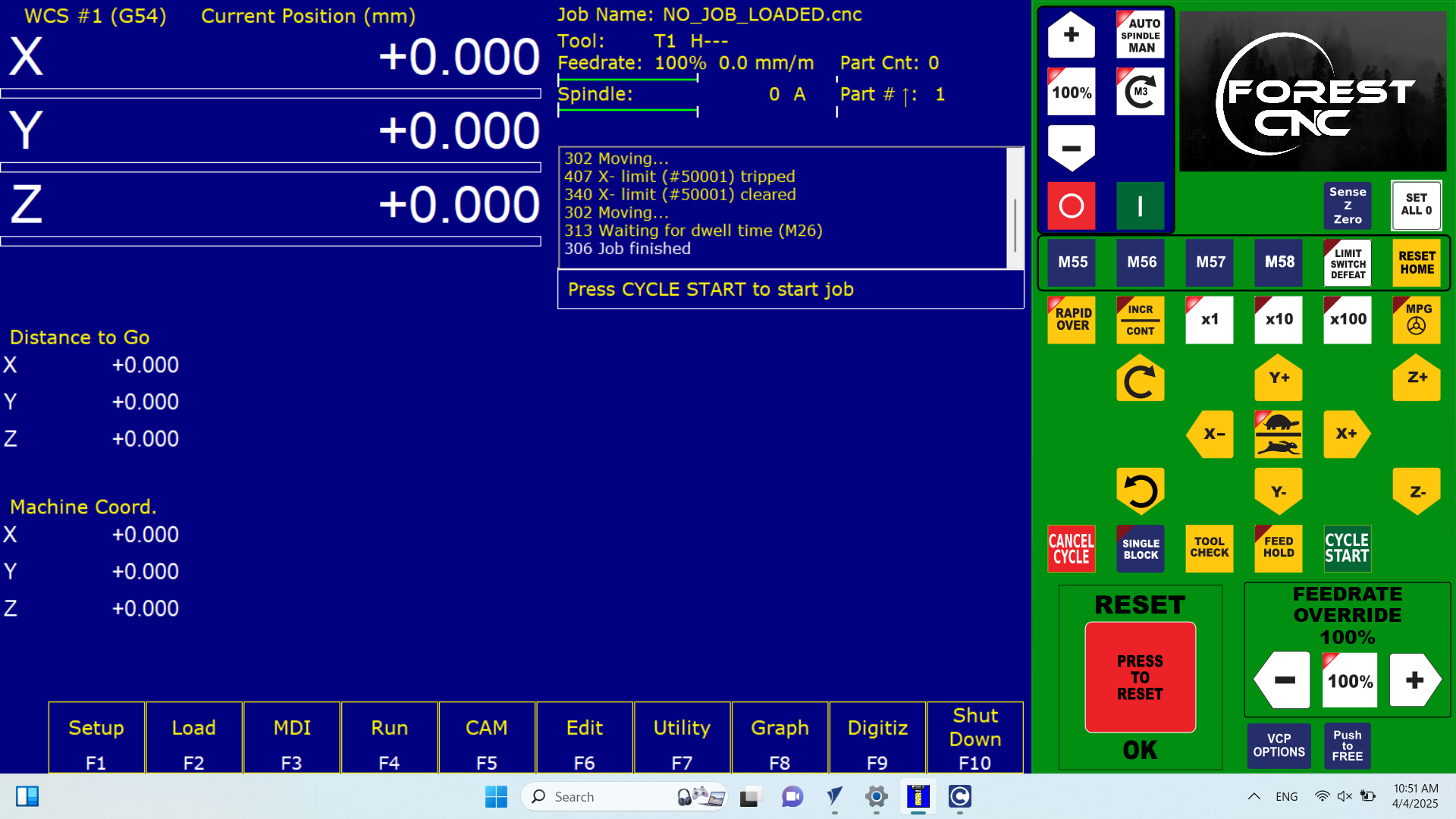
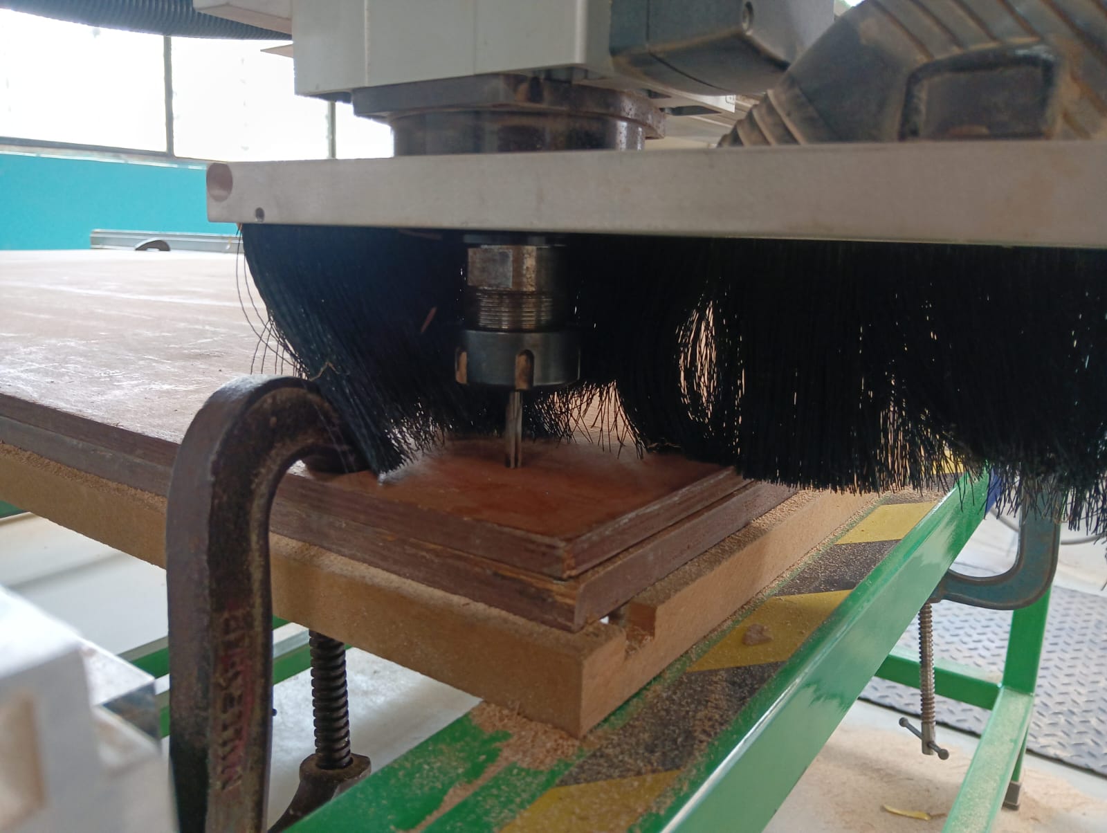
After that, I opened my files in the Forest CNC software and then started the cutting process.

After starting the cutting process, I moved a safe distance away from the machine while carefully observing whether the process was running smoothly.
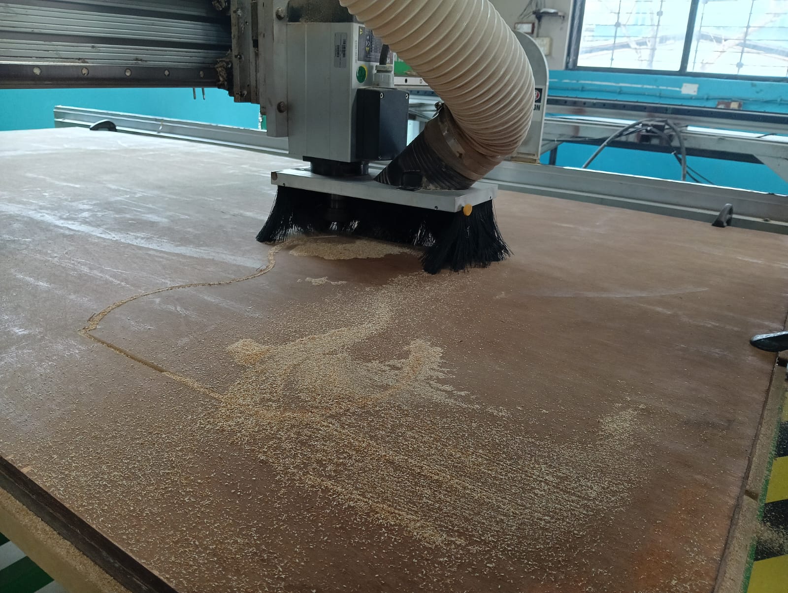
I also monitored the cutting process on the system to ensure everything was running correctly. At the same time, I observed the machine physically to check for any issues, ensuring both were in sync.
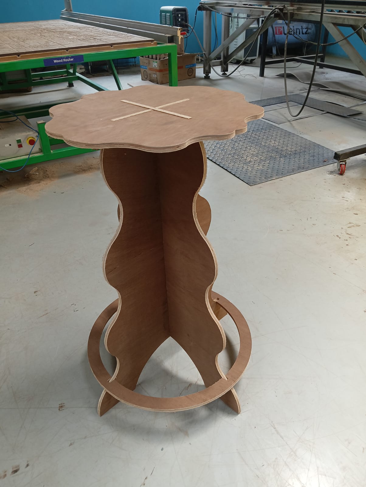
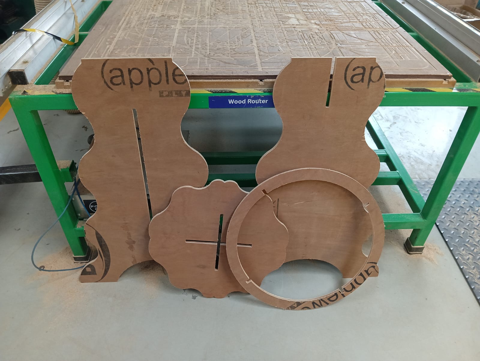
After completing the cutting of all parts, I turned off the machine and carefully collected the cut pieces. Then, I started the assembly process to put everything together.
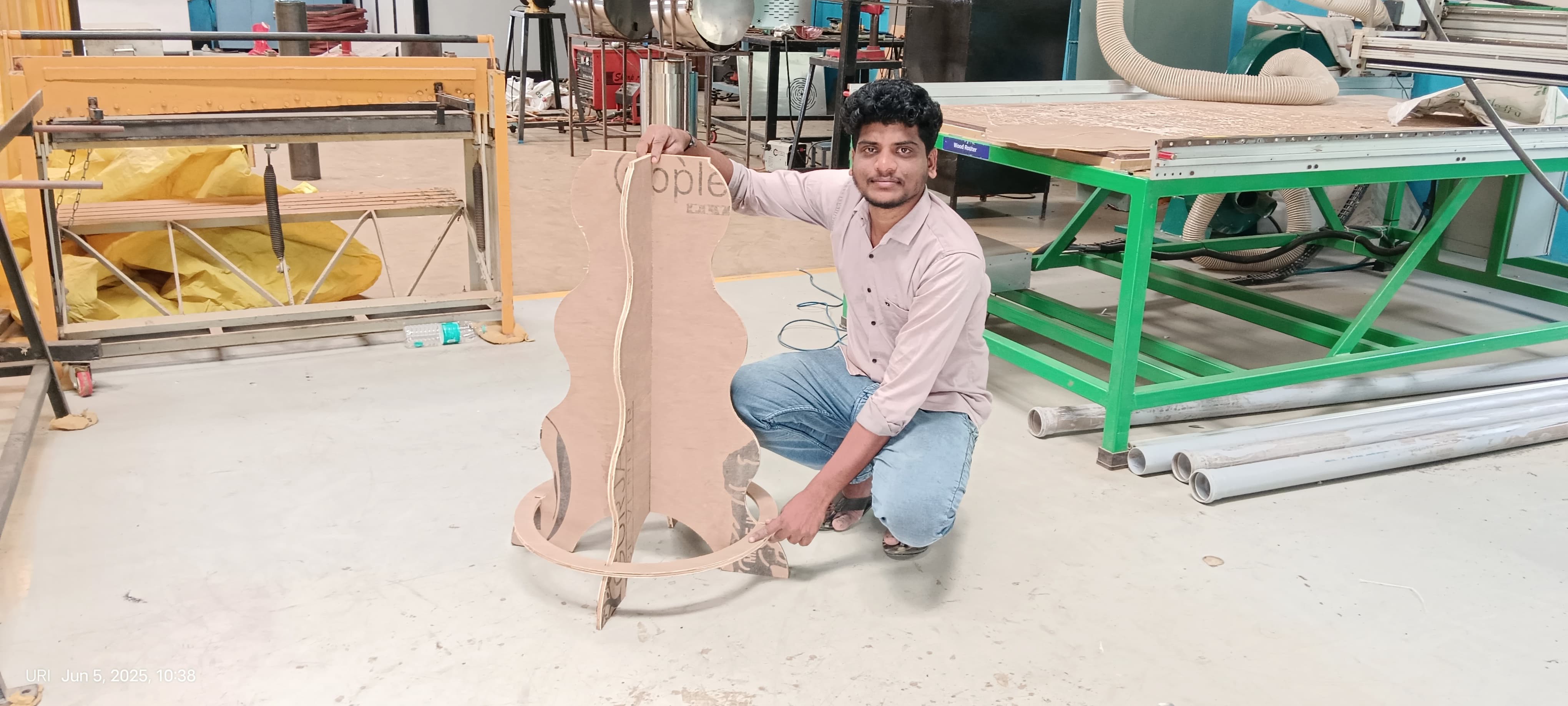
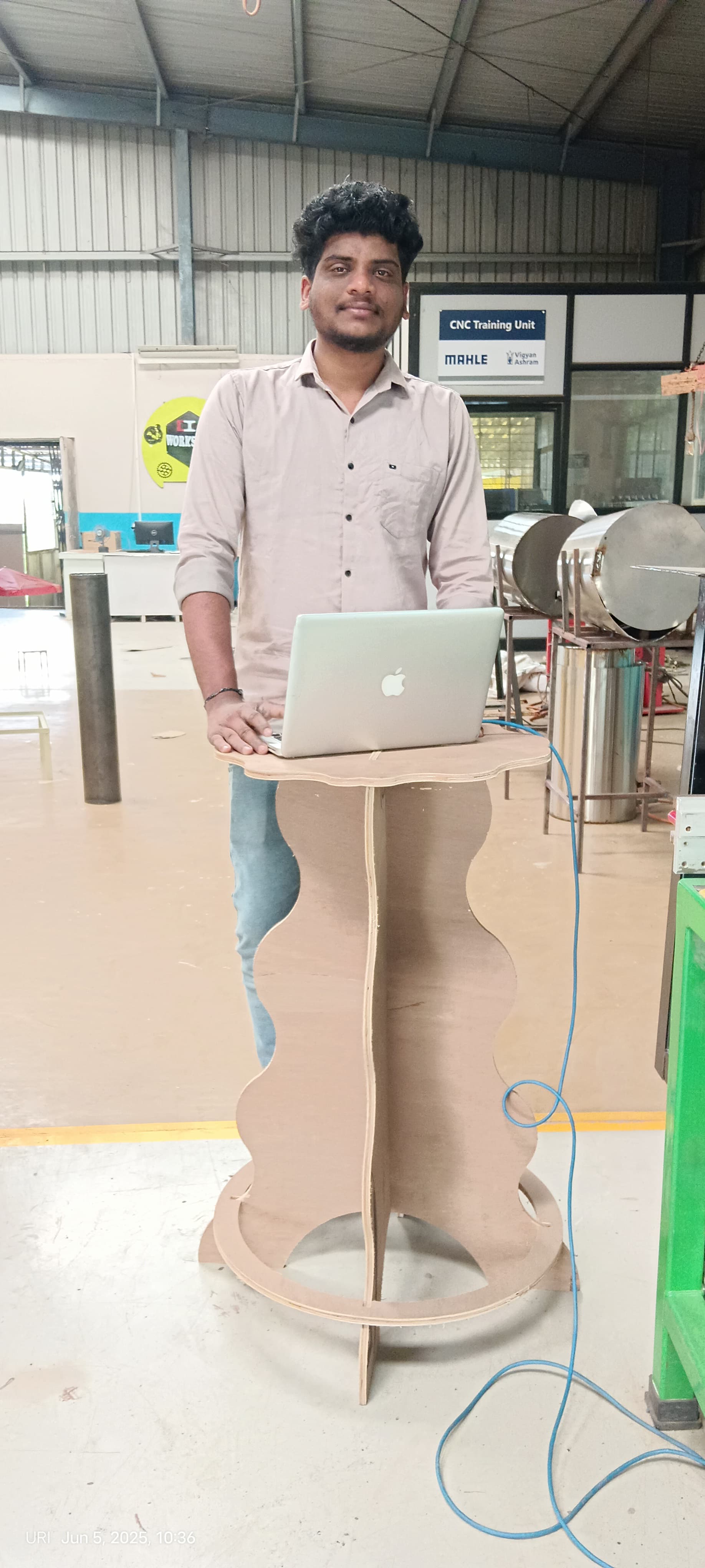
Finally, I successfully assembled my table. I ensured all parts fit correctly and secured them properly. The final structure was stable and ready for use.
Positive Outcomes:
This week, I gained valuable knowledge on operating a CNC router and designing for CNC machining using SolidWorks. I learned how to convert designs into G-code and set up the machine for precise cutting.
While designing the table, I started thinking differently to create a functional and stable structure. This process helped me improve my design thinking skills and approach problem-solving more effectively.
Overall, it was a great learning experience in both CNC operation and design workflow.
Challenges Encountered:
This week, I faced challenges in designing a new and attractive table while ensuring it was suitable for a 12mm sheet.
I had to carefully plan the dimensions and structure to maintain both stability and aesthetics.
Throughout the design process, I made several modifications to improve the overall look and functionality.
Finding the right balance between strength and design was a key challenge.
After multiple iterations, I achieved a design that met all requirements.