Assignment 16: Wildcard Week
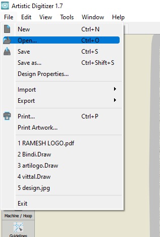
During the wildcard week, I explored and learned several fabrication processes, focusing on sheet metal design, plasma cutting, and logo engraving. I began by designing a sheet metal part, where I learned how to create accurate 2D profiles considering material thickness and bend allowances to prepare the design for cutting. After completing the design, I used a plasma cutting machine to cut the sheet metal. This involved setting up the machine, adjusting parameters like speed and power, and operating it safely to produce precise cuts based on my design. To add a personal touch, I used Artistic Digitizer v1.7 software to digitize and prepare the logo for my YouTube channel. Through this software, I learned how to import and trace images, then generate engraving paths suitable for the engraving machine. Overall, this week gave me valuable hands-on experience with digital design, CNC fabrication, and engraving techniques.
Highlight Moments of the Week
Individual Assignment
Objectives of Individual Assignment:
- Design and produce something with a digital fabrication process (incorporating computer-aided design and manufacturing) not covered in another assignment, documenting the requirements that your assignment meets, and including everything necessary to reproduce it.
Basics of Plasma cutting
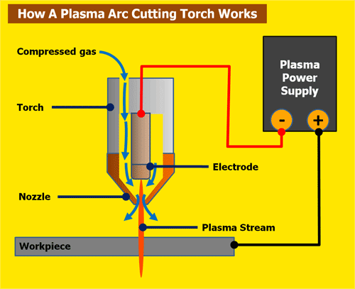
Plasma cutting is a process that cuts through electrically conductive materials by means of an accelerated jet of hot plasma. Typical materials cut with a plasma torch include steel, stainless steel, aluminum, brass and copper, although other conductive metals may be cut as well. Plasma cutting is often used in fabrication shops, automotive repair and restoration, industrial construction, and salvage and scrapping operations. Due to the high speed and precision cuts combined with low cost, plasma cutting sees widespread use from large-scale industrial computer numerical control (CNC) applications down to small hobbyist shops. Click here to read more.
What is Plasma :
Plasma is a high-temperature, electrically conductive gas made by ionizing air or gas using an electric arc. In plasma cutting machines, this ionized gas forms a plasma jet that melts metal at the cut point. The machine forces this jet through a small nozzle to precisely cut through electrically conductive materials like steel or aluminum. The high speed and temperature of the plasma arc enable clean and quick cuts. Plasma cutting is widely used in fabrication, automotive, and metalworking industries for its efficiency and accuracy. Click here to read more.
References: Reference
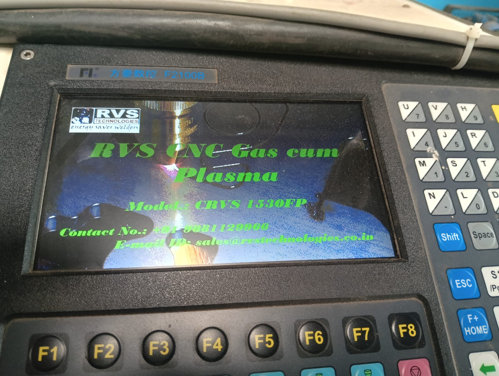
CNC Plasma Cutting Machine:
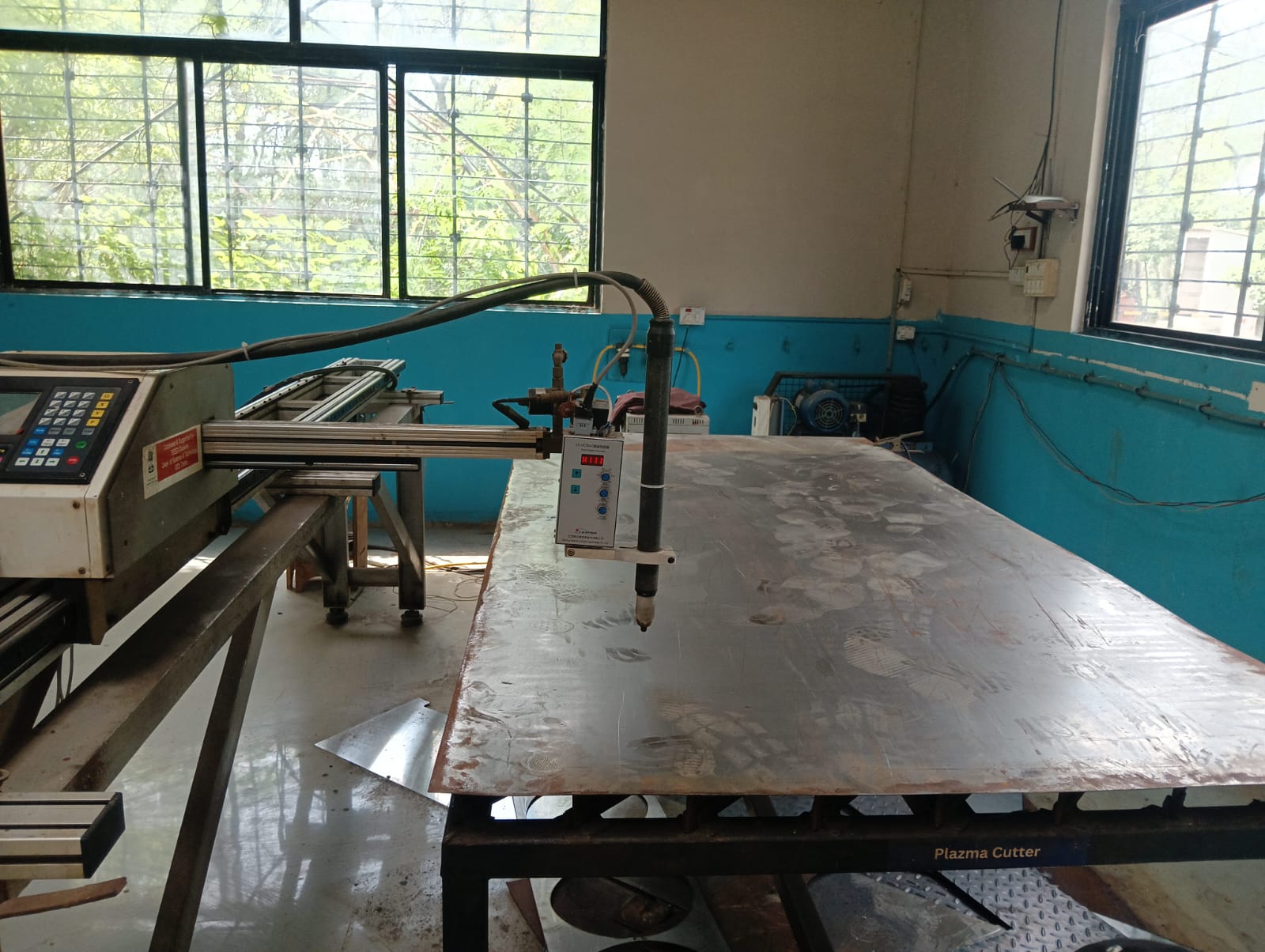
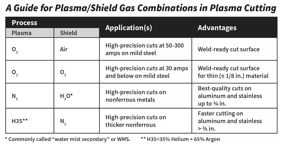
plasma cutting machine parameters :
References: Reference
CAD design in SolidWorks for sheet metal :
This week, I used SolidWorks to complete my assignment. For the design, I utilized the Sheet Metal tool. Below, I am presenting the step-by-step process I followed.
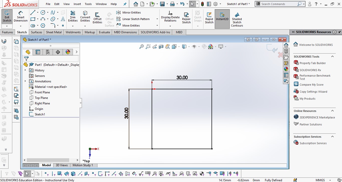
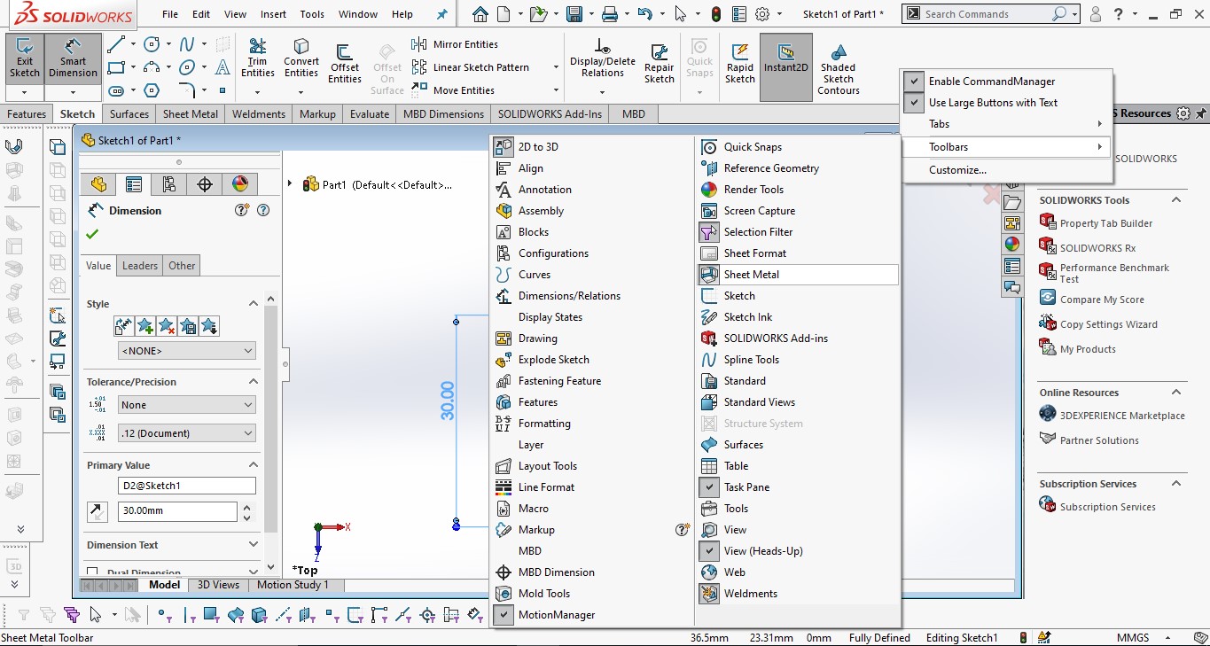
I created a 30x30 mm square, and then used the Base Flange feature to convert it into a sheet metal body. After that, I applied the Edge Flange tool to create the bends. The image below shows the process.
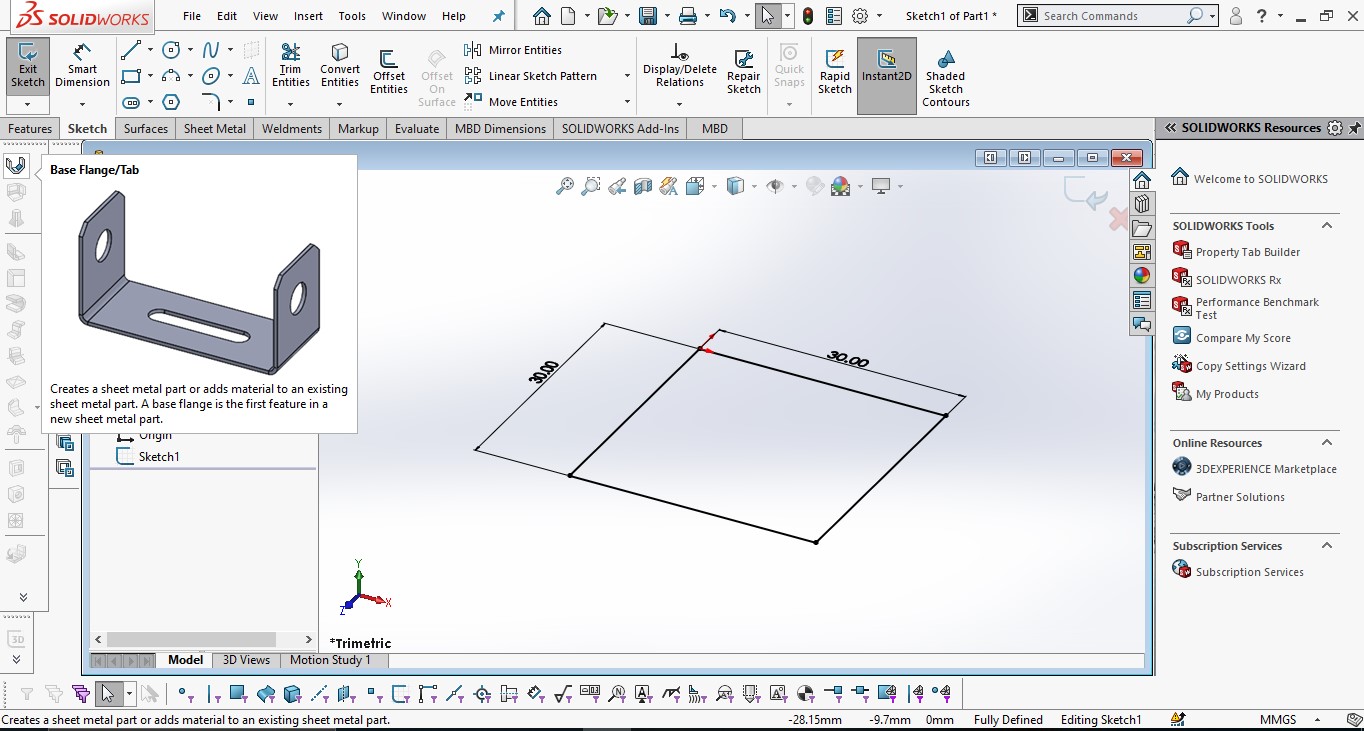

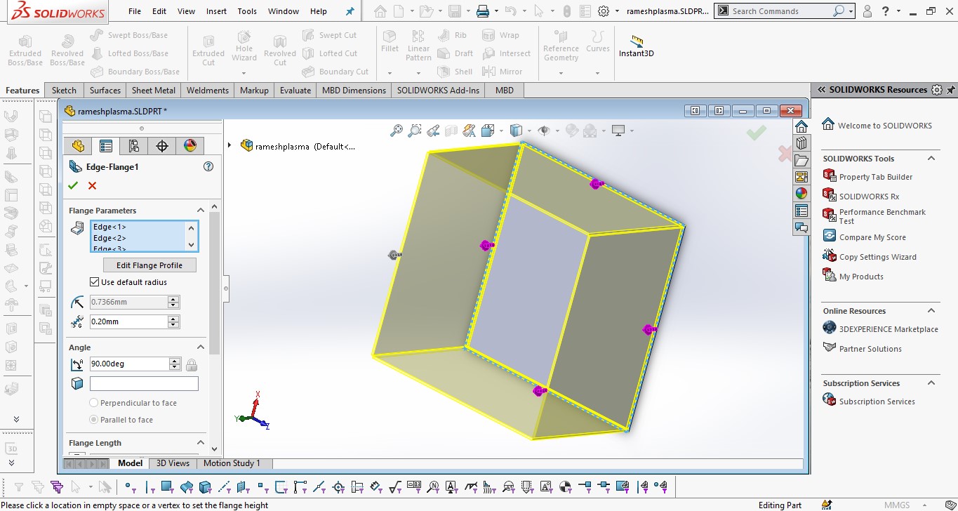
After completing all the edge flanges, the final 3D sheet metal model was ready.
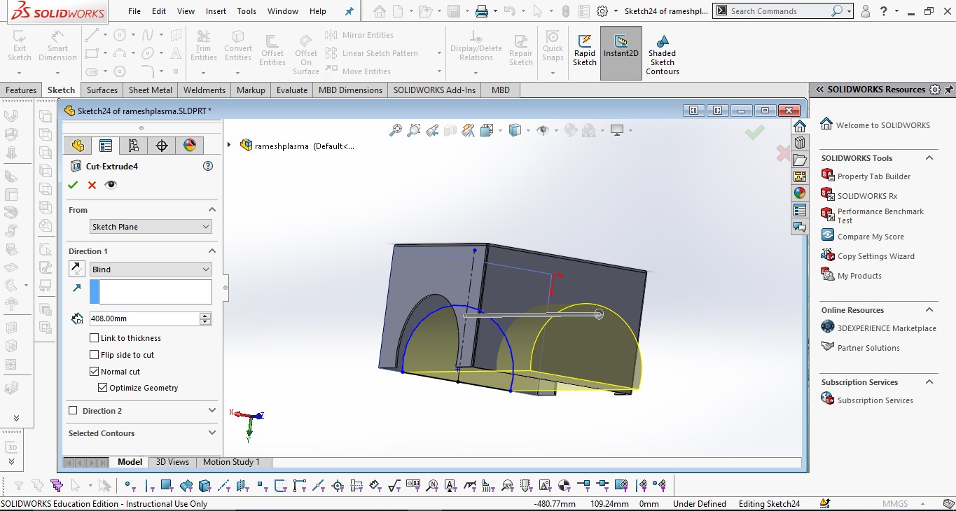
I cut some extruded parts to prepare the legs of the stool.
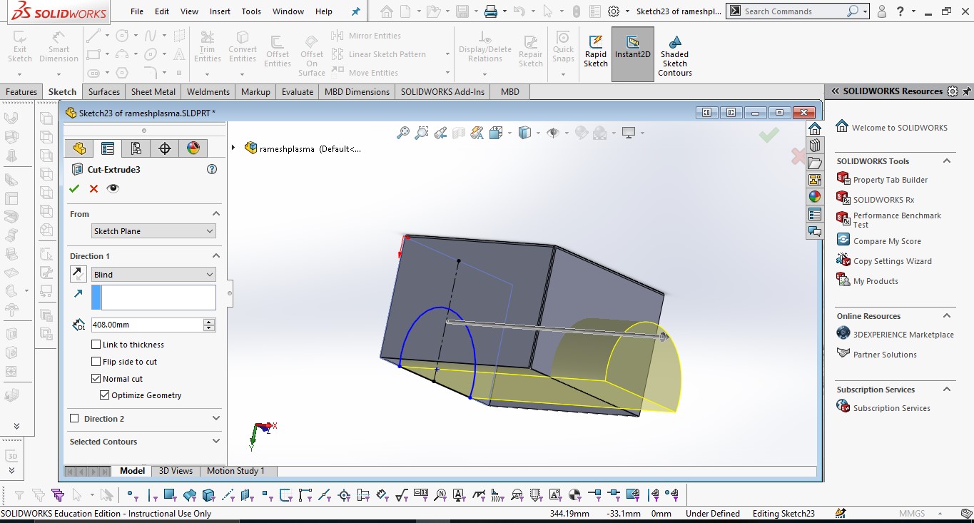
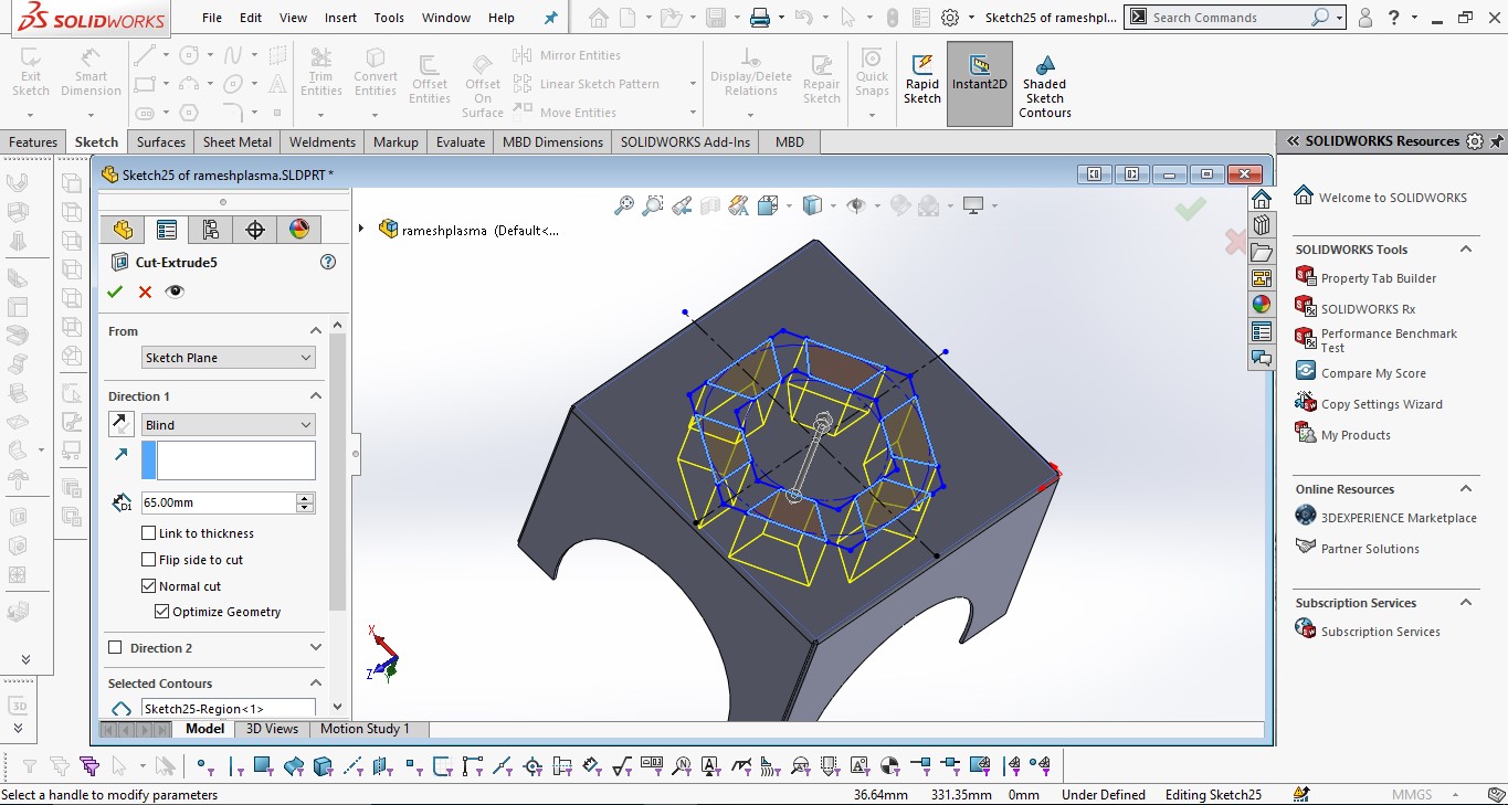
I created some design features on the top surface to enhance the appearance and provide a locking
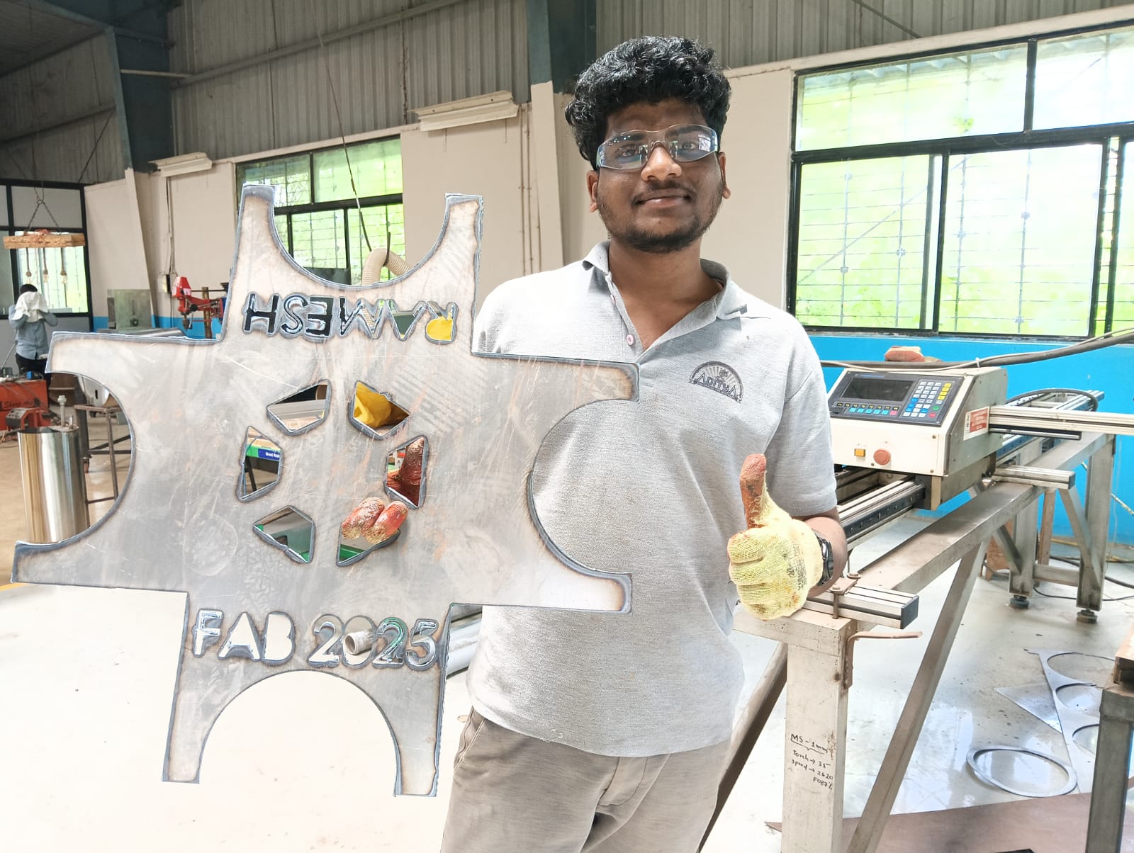
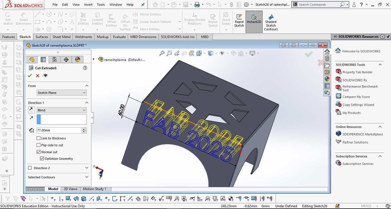
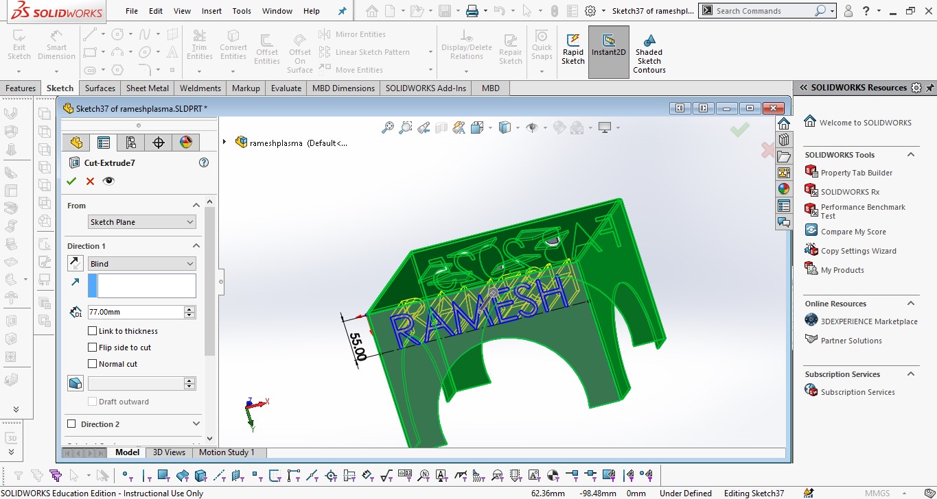
I engraved my name and "Fab 2025" on the sheet metal as a personal touch and for my happiness.
I used the Unfold option to unfold the sheet metal. Below, I am showing the image of the unfolded view.
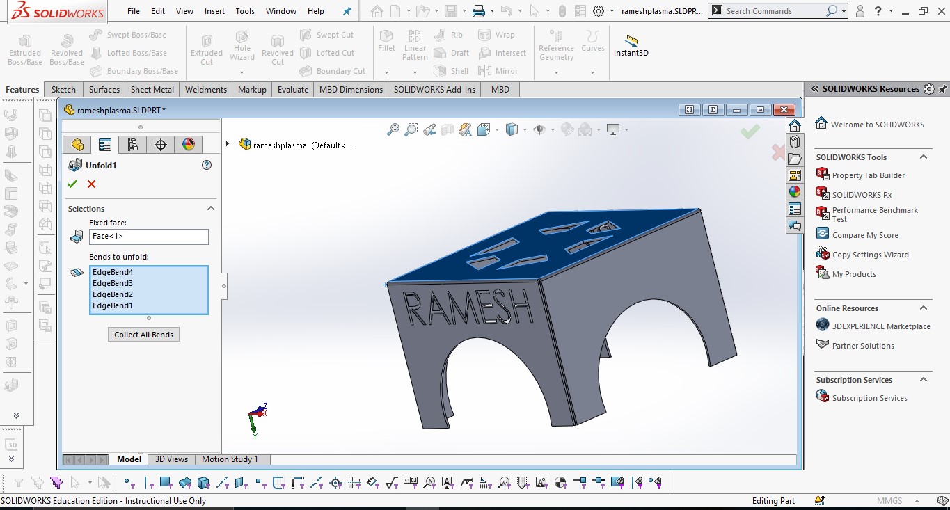
After unfolding the design, I am showing the image below.
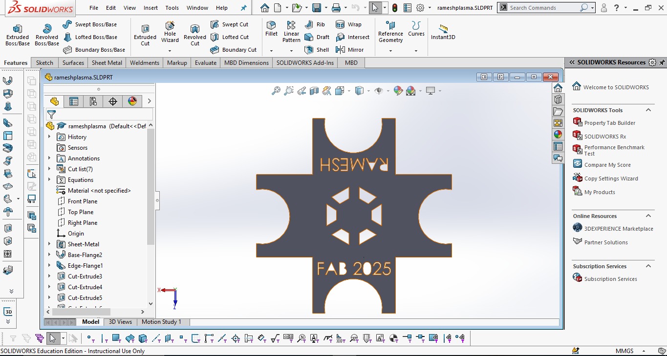
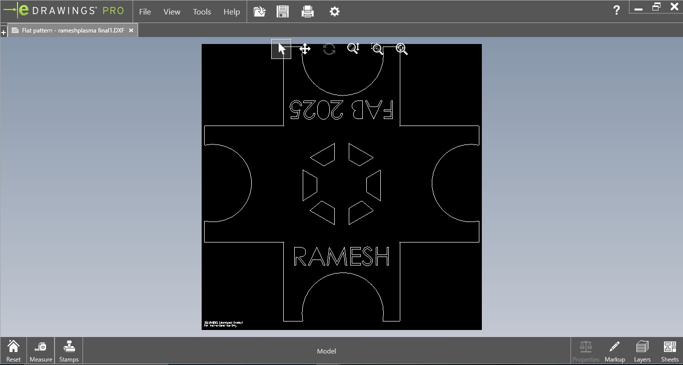
I saved the unfolded sheet metal design in DXF format.
Generating Tool Path with FastCAM
First, I imported the DXF file into FastCAM using the following process:
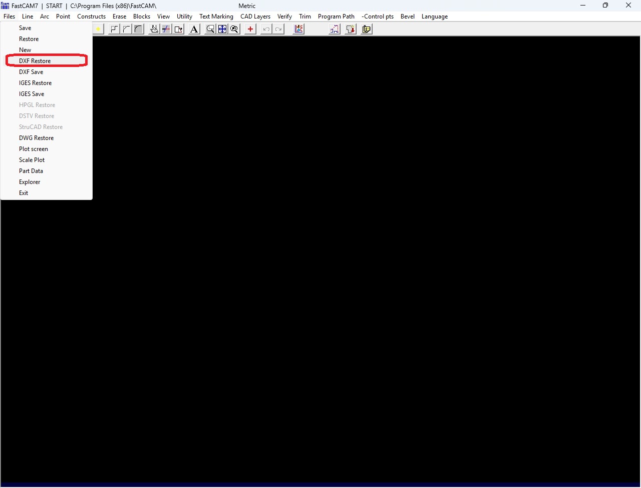
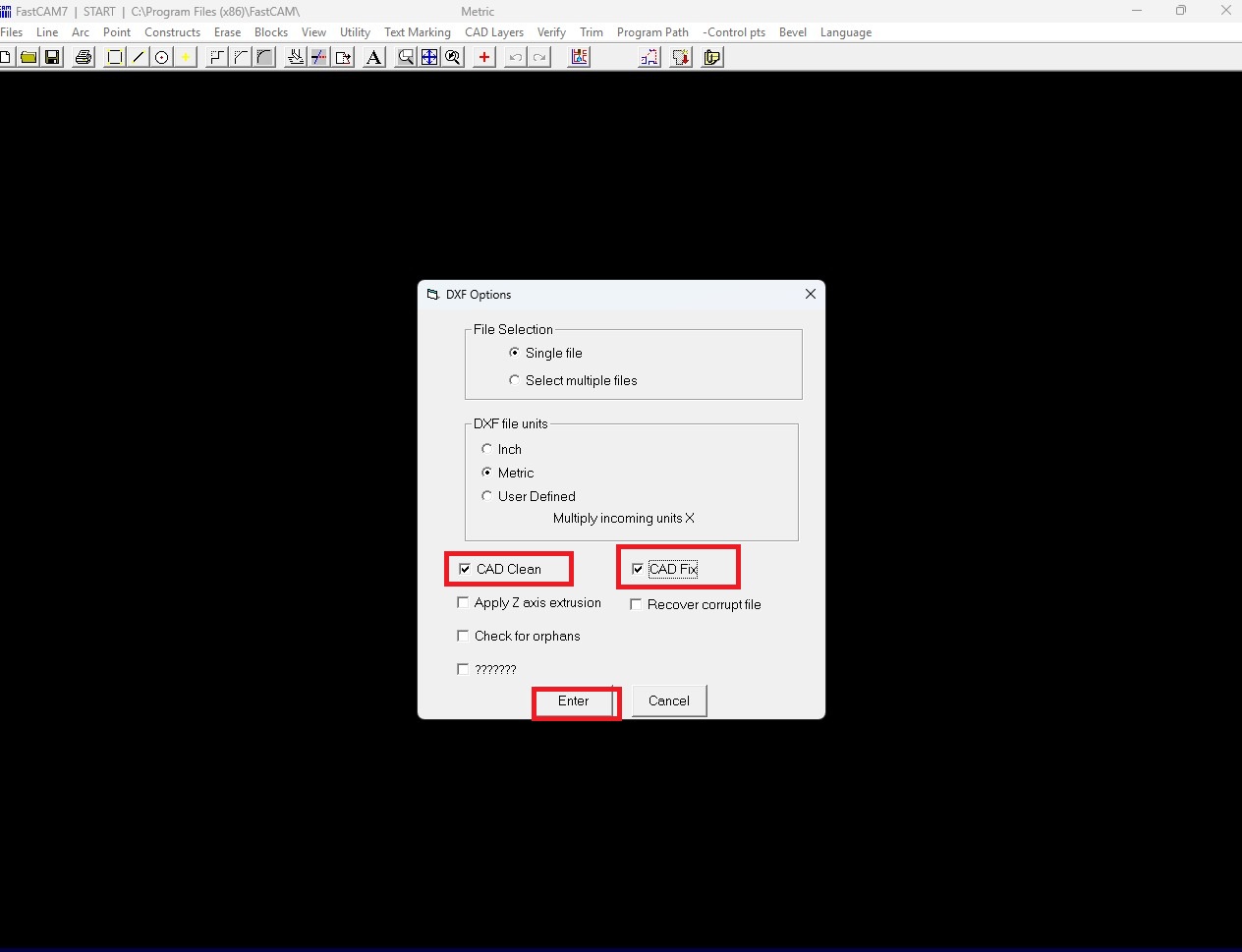
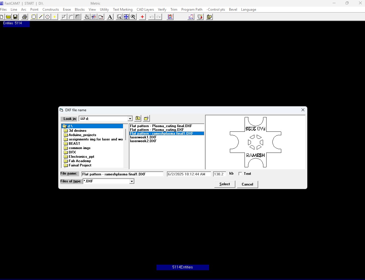
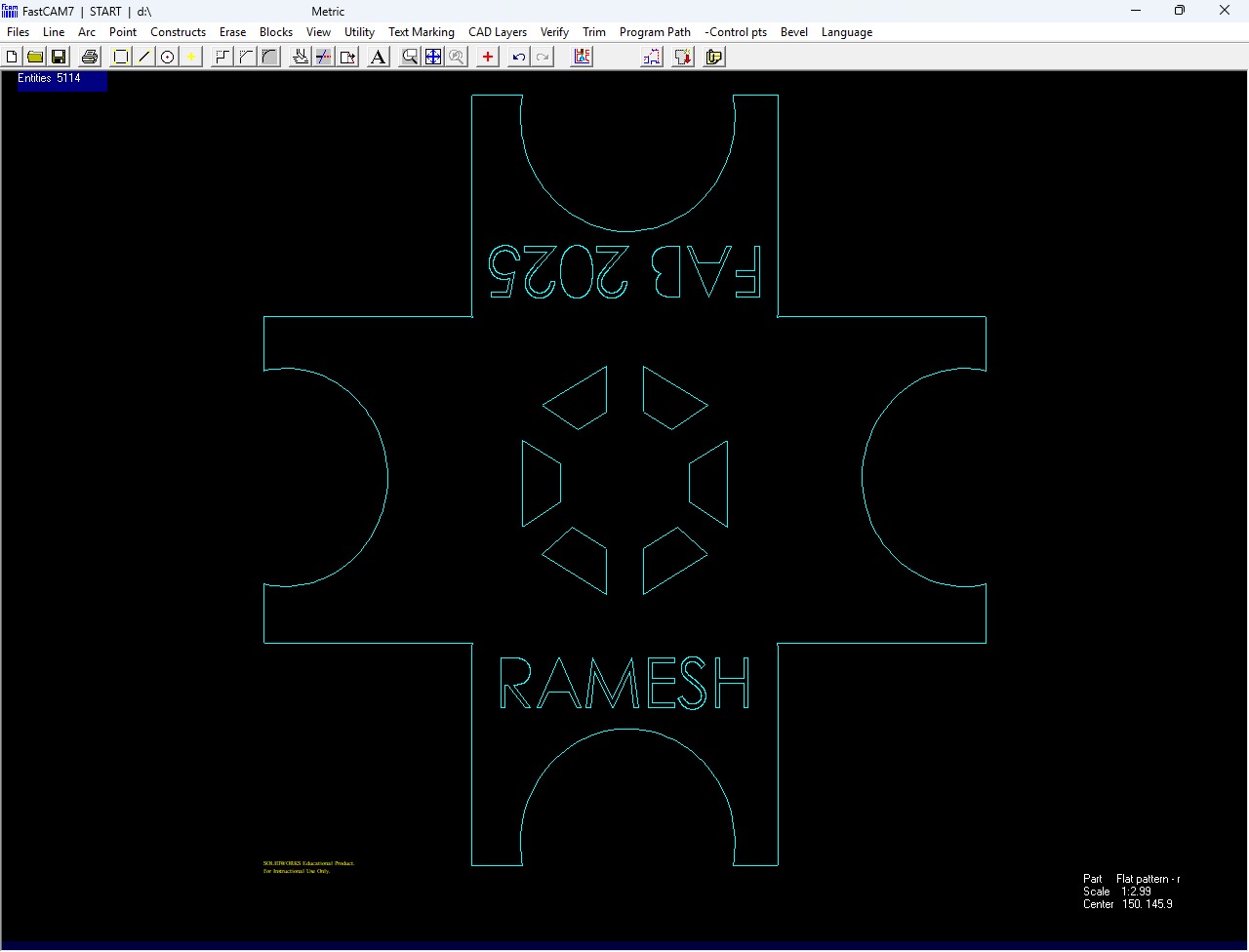
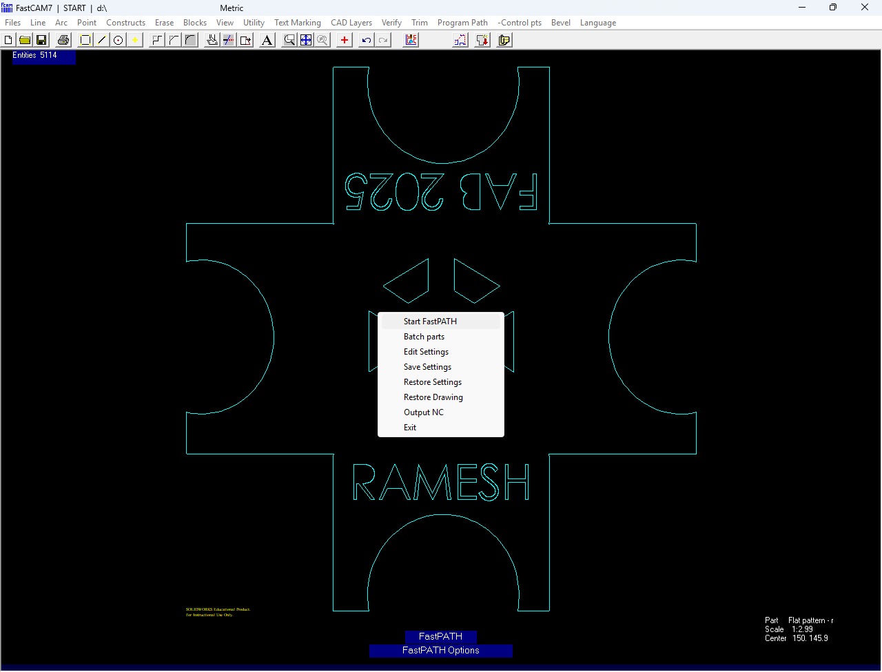
After that, I selected my DXF file from its location and clicked the "OK" button to import it. Below, I am showing how my design looks in FastCAM.
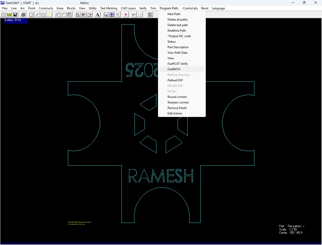
To generate the cutting path, I selected the Programming Path option and then chose FastPath. After that, I clicked on Start FastPath. Below, I am showing how I created the cutting path.
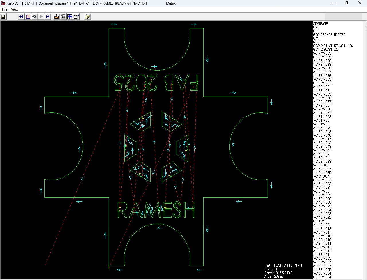
After creating the path, the G-code was displayed. Below, I am showing the image of the generated G-code.
Sheet Metal Cutting Using Plasma Cutting Machine :
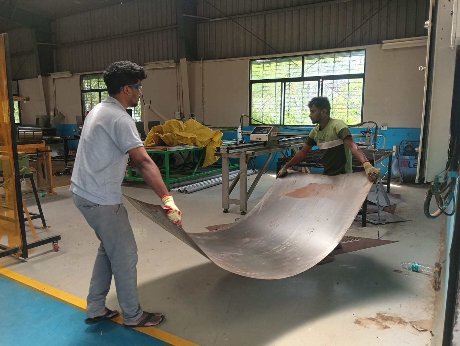
First, I placed the sheet metal on the machine with the help of my friend Chadwik. We ensured that the sheet was properly aligned and securely positioned before starting the cutting process.

After placing the sheet metal on the machine, we checked whether it was properly fitted or not.
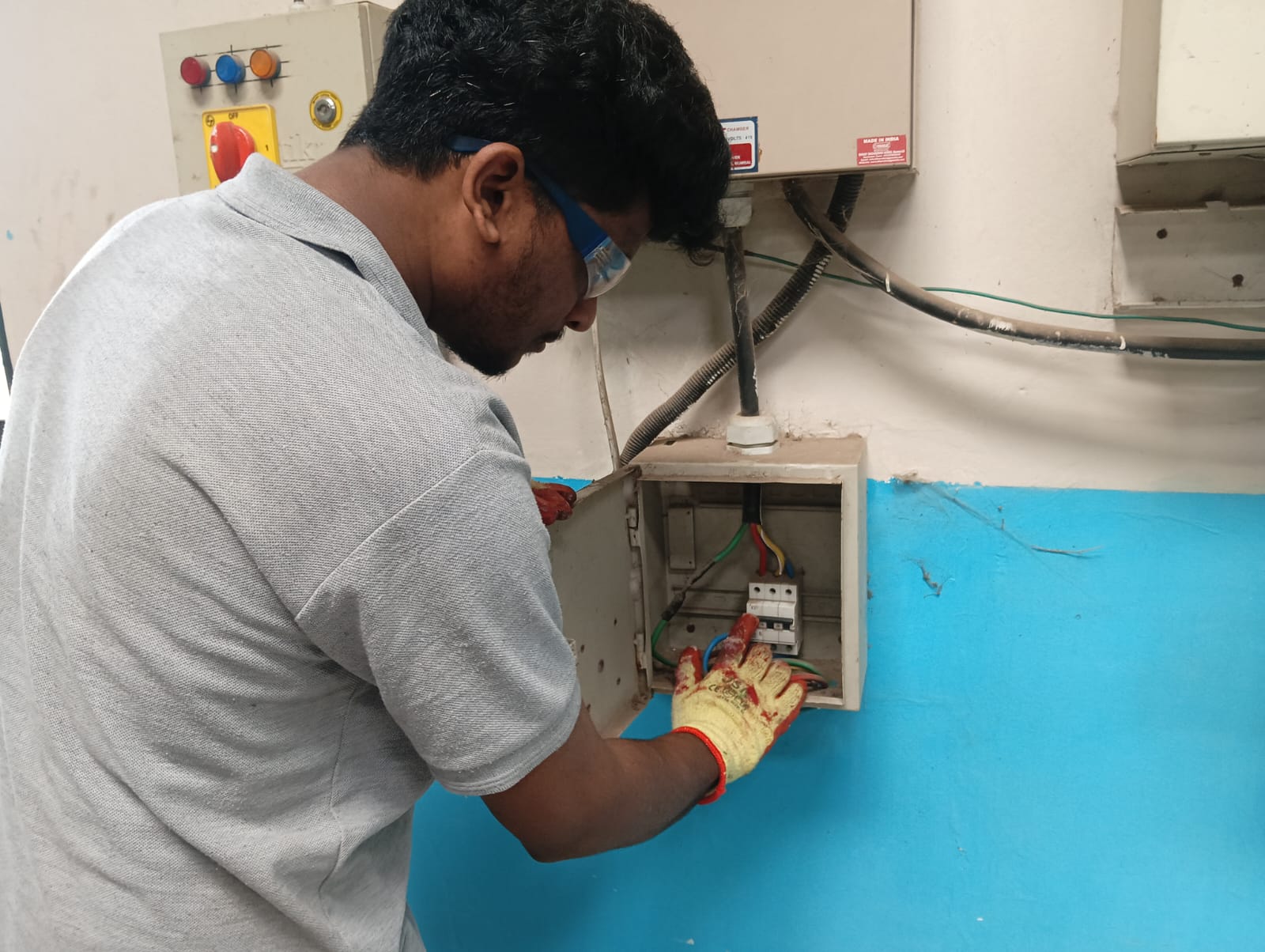
After that, I turned on all the switches and the air compressor. Before switching them on, I checked the air pipe to ensure there were no leaks. After confirming everything was in proper condition, I continued with the cutting process.
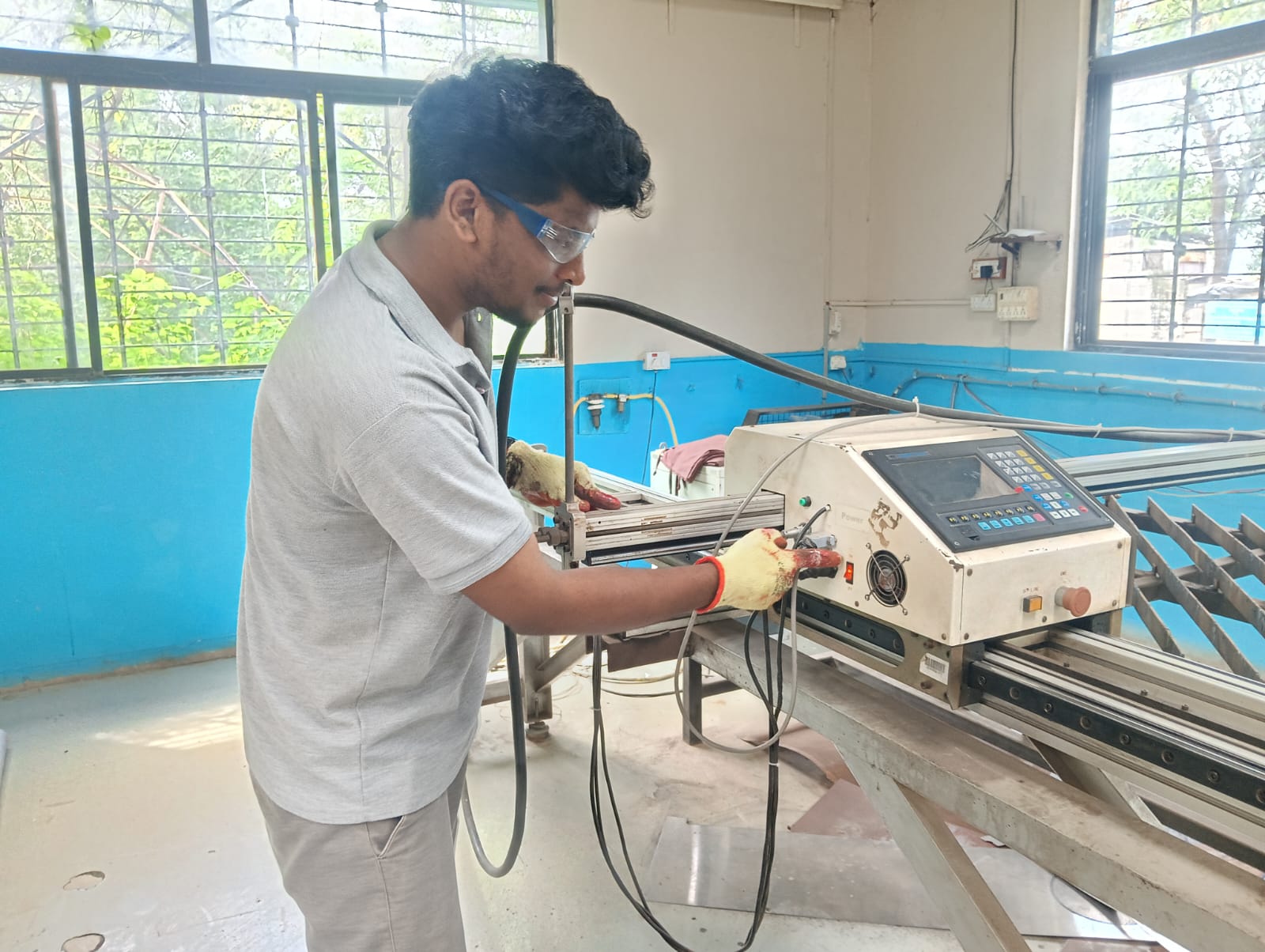
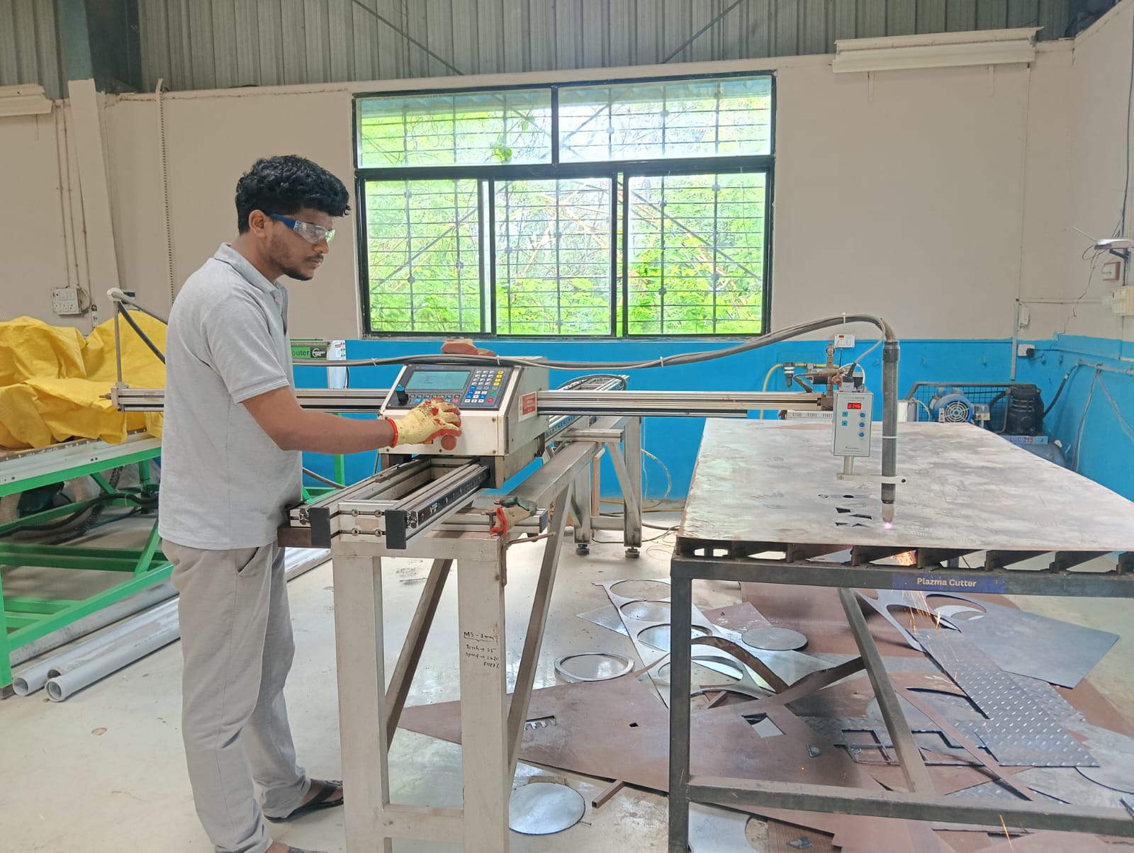
After successfully powering on the machine, I inserted the USB drive into the system. Then, I selected my G-code file and started the cutting process.

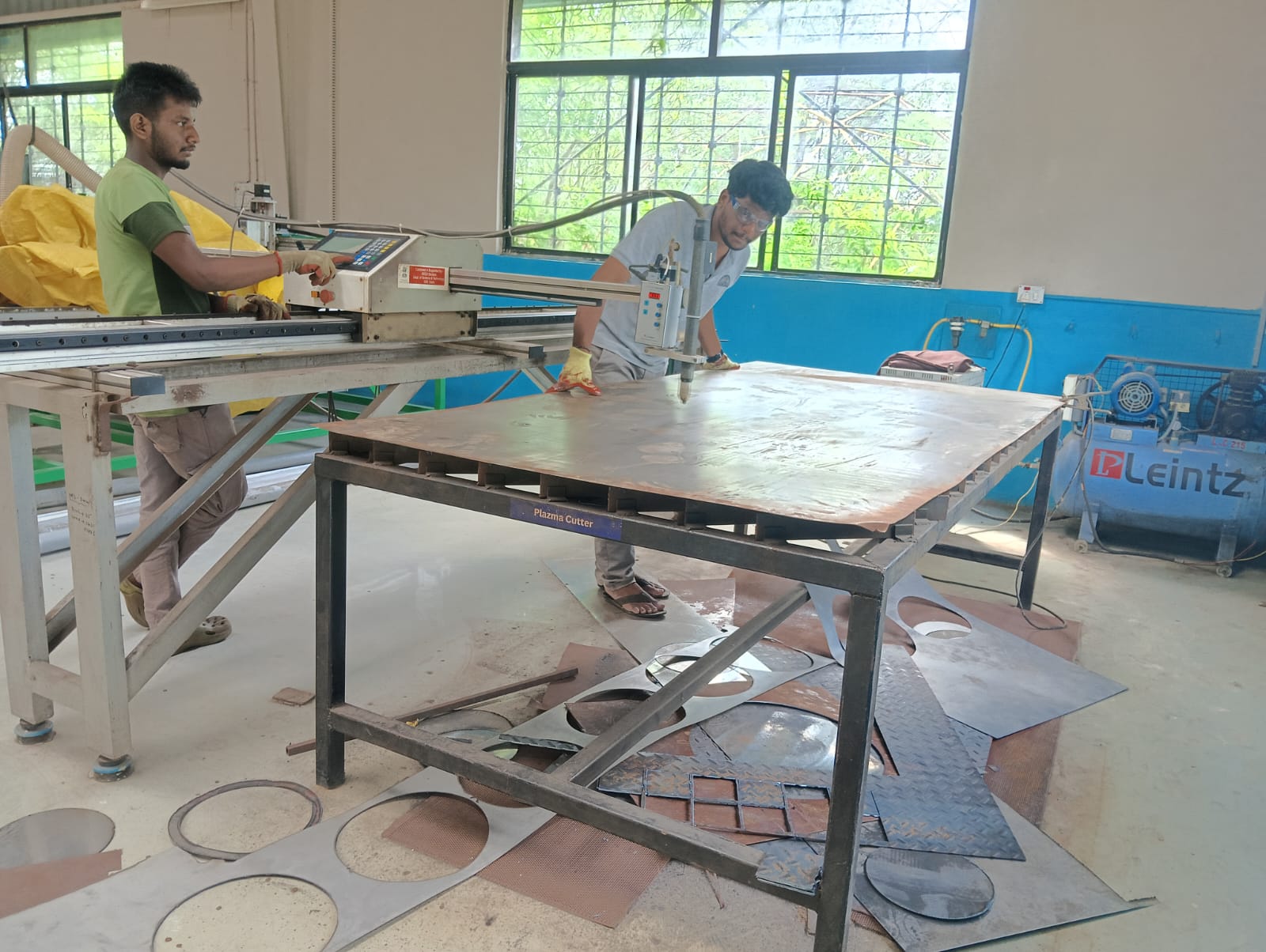
Before starting the cutting, I set the zero position of the nozzle. After that, I continued with the cutting process.
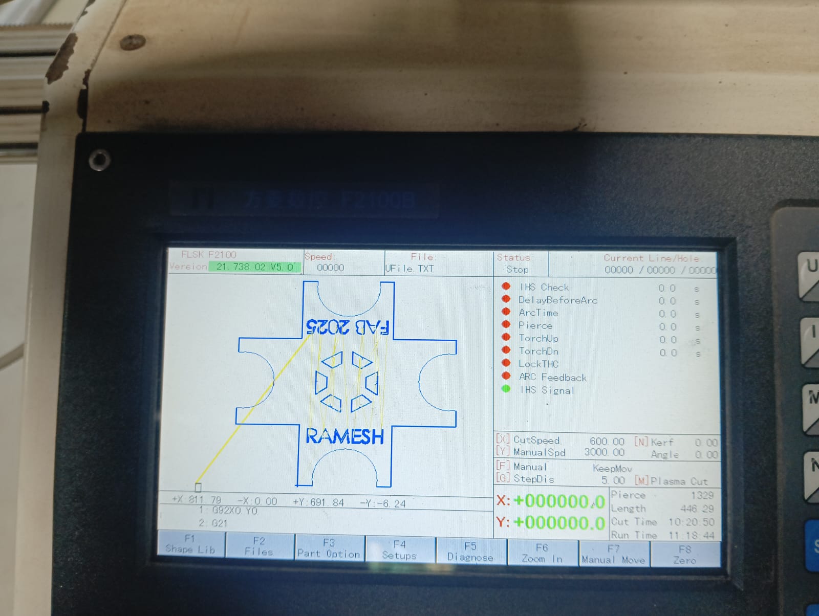

Below, I am showing how my cutting is progressing.
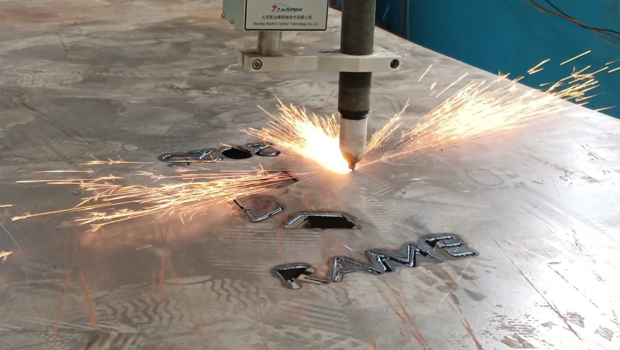
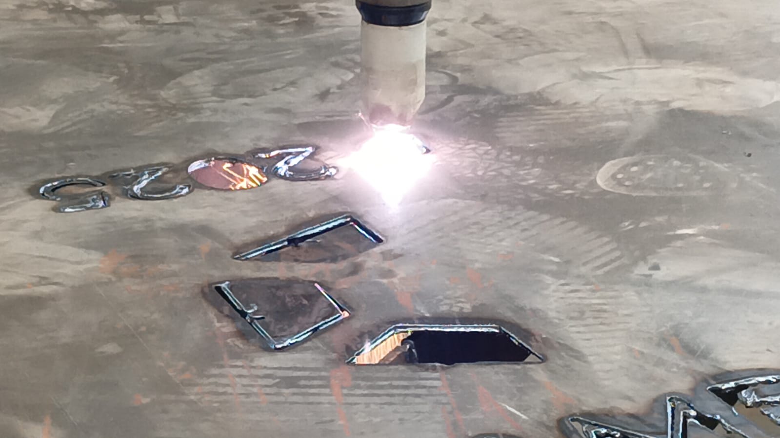
While the cutting was in progress, I adjusted the Z-axis because my sheet metal was uneven. If I didn’t adjust the Z-axis, the cutting nozzle could have damaged the sheet or caused blockages. I carefully monitored the process to ensure the cutting was proceeding properly.
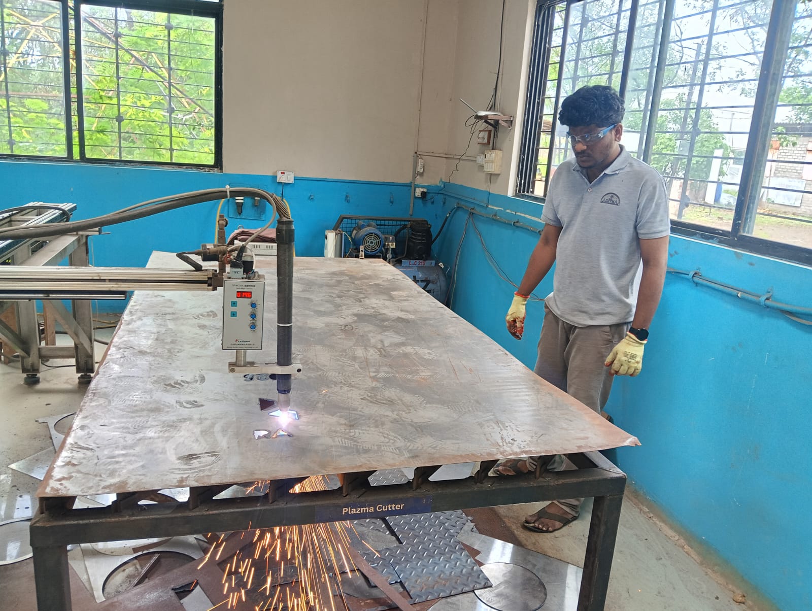
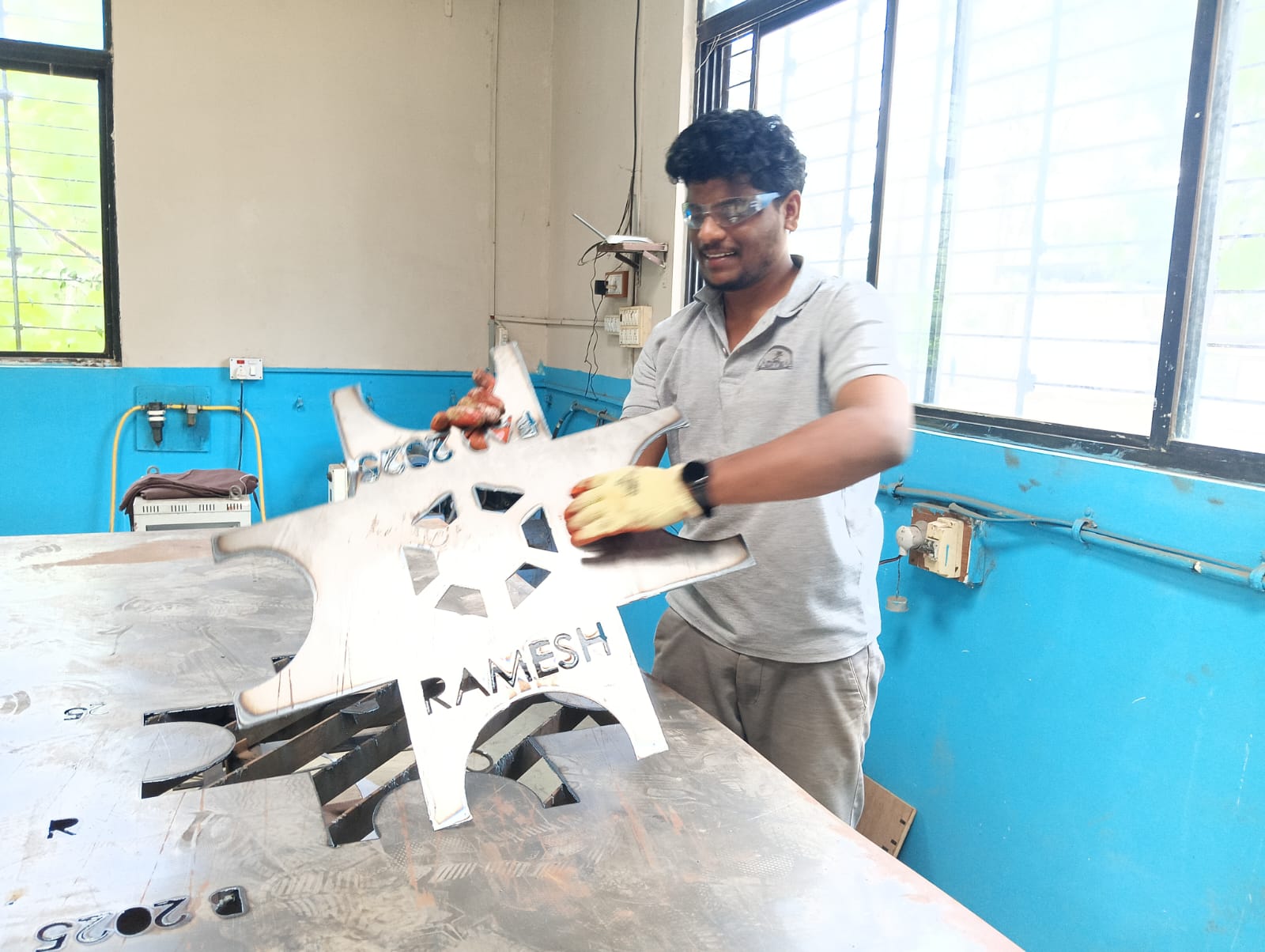
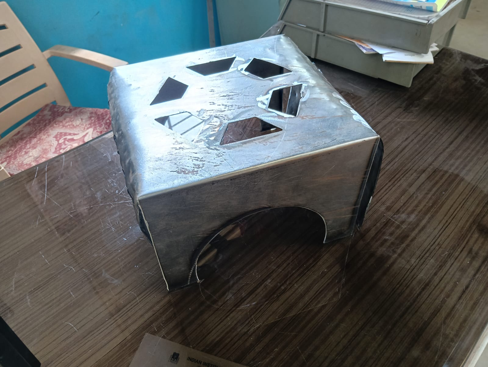
I successfully completed the cutting process. Below, I am showing the results and sharing my happiness. I am very satisfied with how the final cut turned out

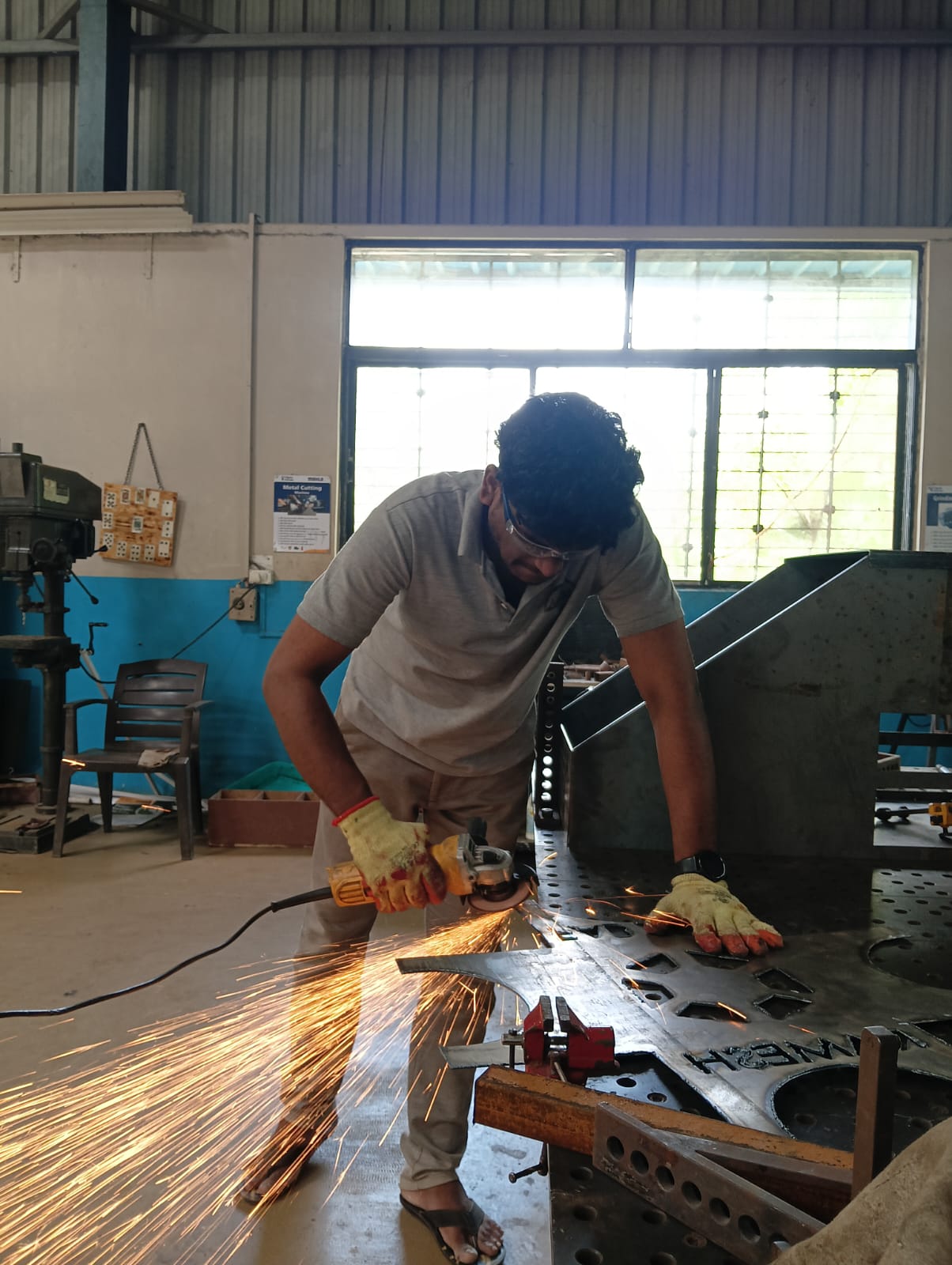
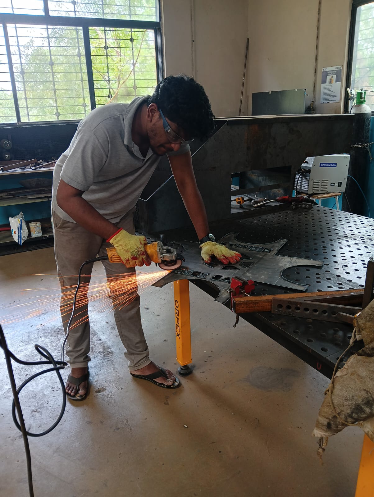
After completing the cutting, some leftover metal scraps remained on the sheet metal. I ground those areas to achieve a smooth and clean finish.
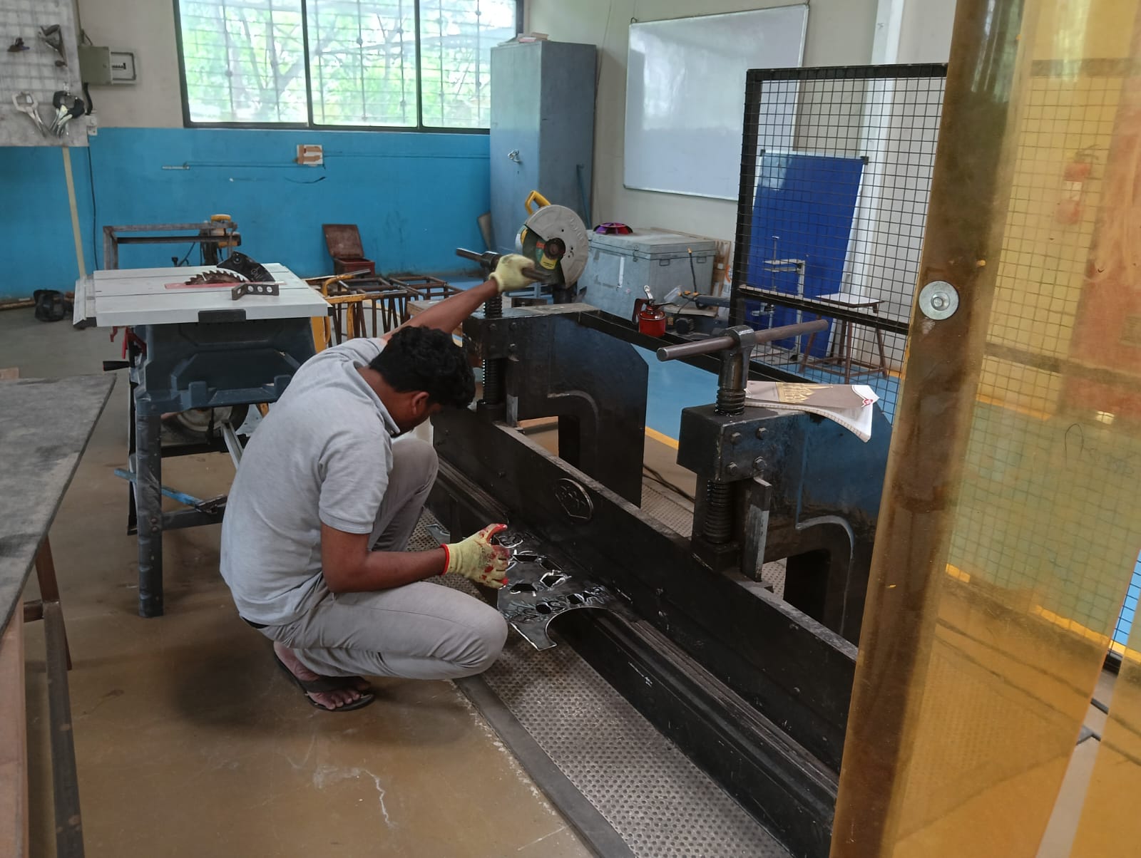
After completing the grinding process, I bent the sheet metal using a bending machine. Below, I am showing how I used the machine and bent the sheet.
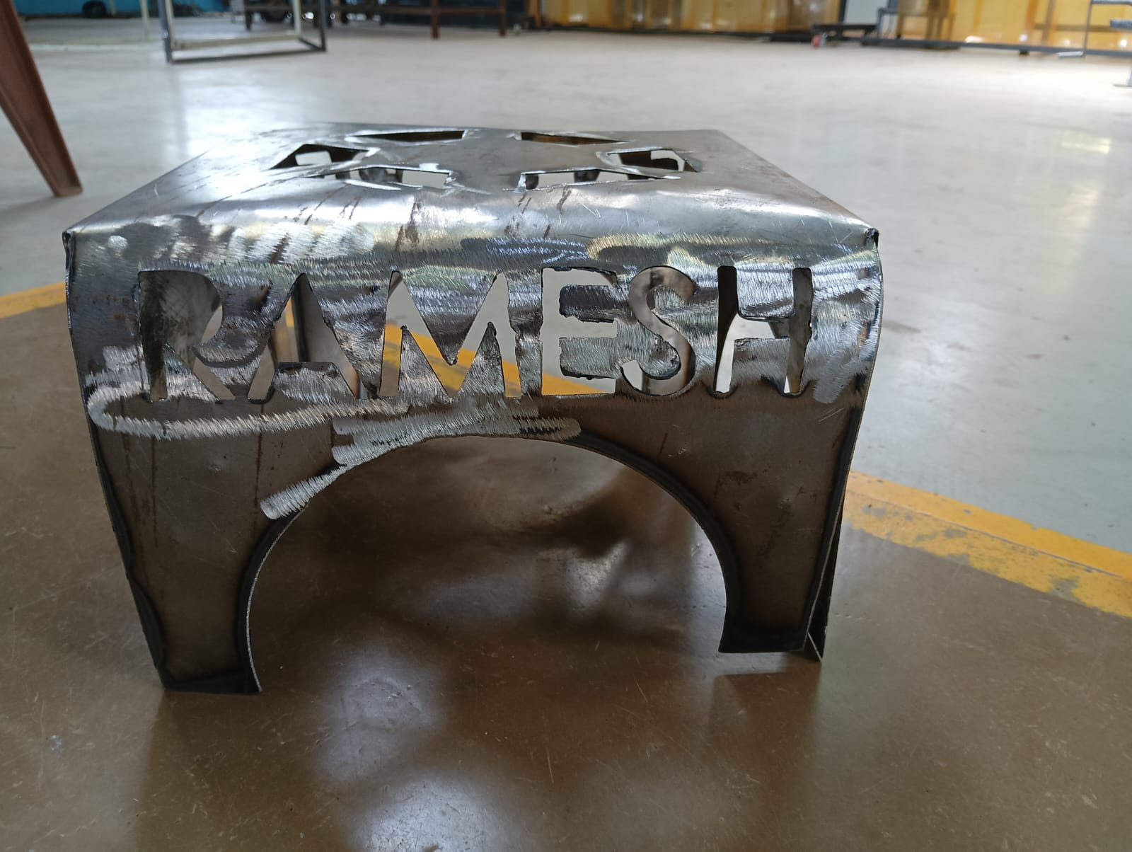
After bending, I am showing the final results below.
The final product matches the design and meets the desired dimensions.
Logo Creation Using Embroidery Machine :
Embroidery Sewing Machine
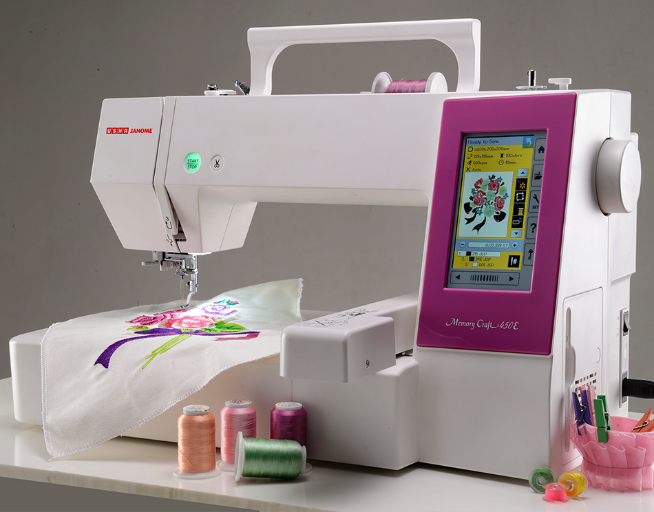
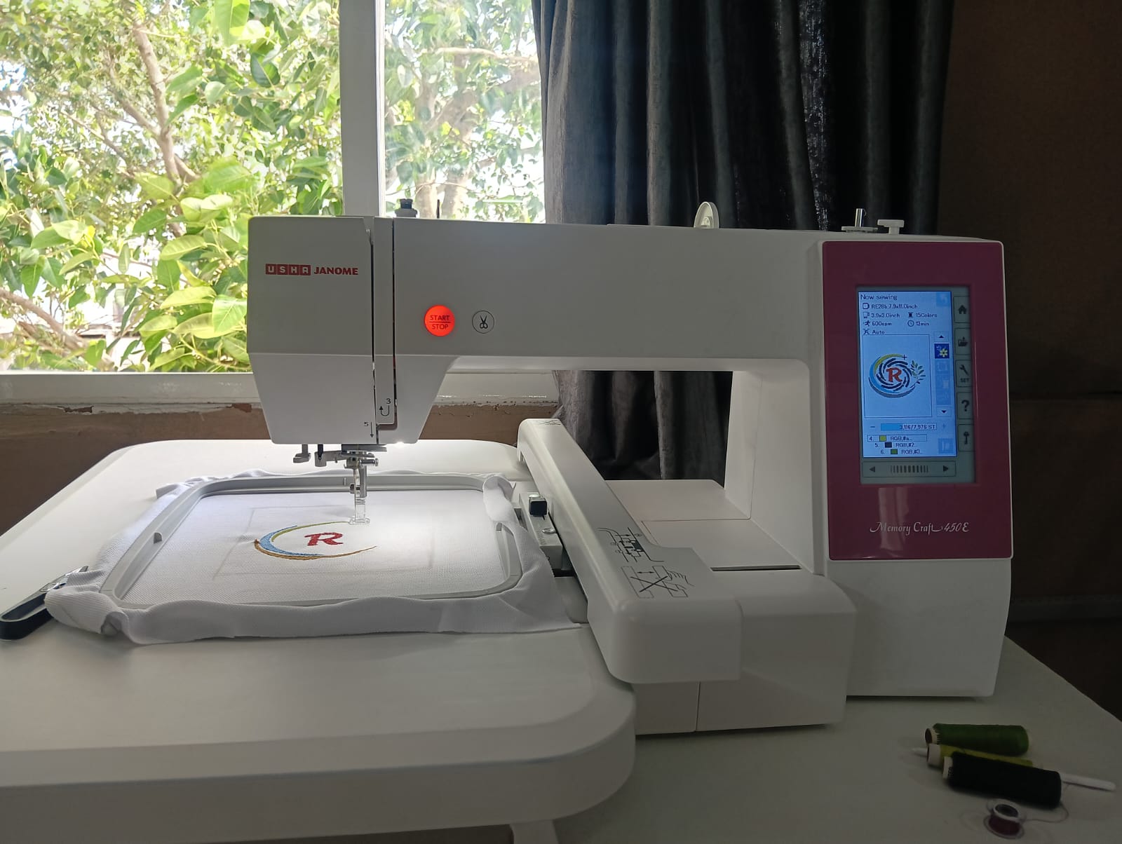
Machine Used: Memory Craft 450E (Usha Janome)
An efficient embroidery machine, the Memory Craft 450 E offers a speed of 860 spm (stitches per minute) and is enabled to embroider designs of up to 200 X 280 mm making it great for boutiques. It has two hoops – RE28b: 200 mm X 280 mm and SQ20b: 200 mm X 200 mm, which are adjustable even after embroidery has begun. Its extra wide table supports large projects and its free Digitizer Jr V5 software allows editing of existing designs and creation of customised designs.
Click here to read more.
Referenc: Reference,
Logo Design Using CorelDRAW :
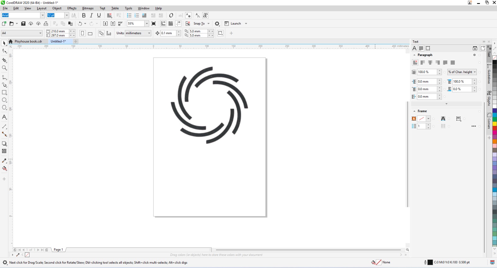
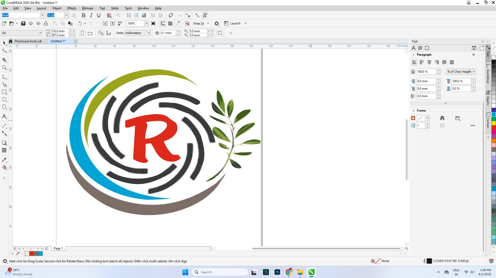
First, I started designing using CorelDRAW. Initially, I didn’t have a clear idea of what kind of logo to create, so I began experimenting with some simple shapes and elements. Below, I am showing the initial steps of my design process.
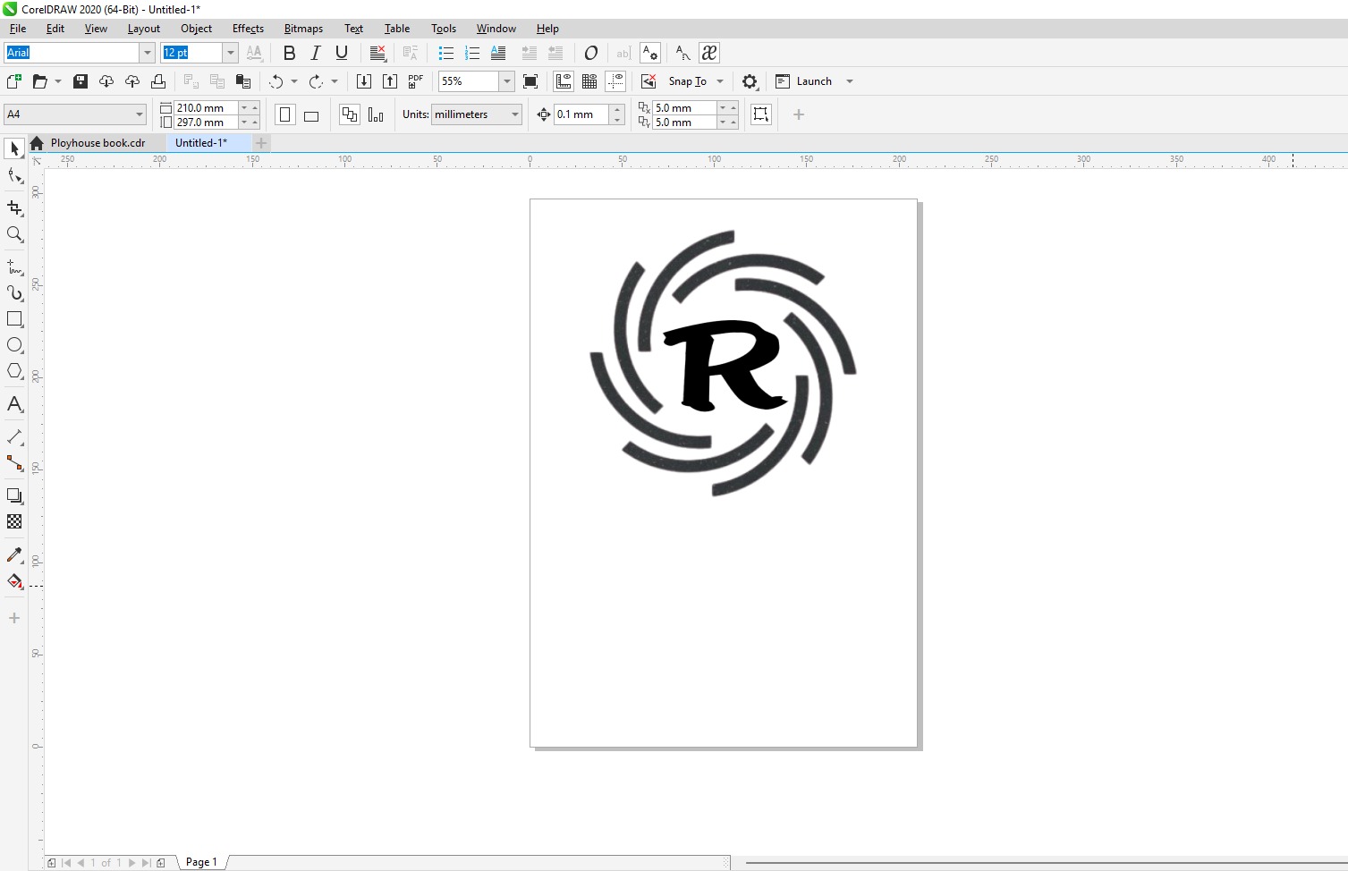
After that, I added my initials in the middle of the logo to make it more personalized and creative.
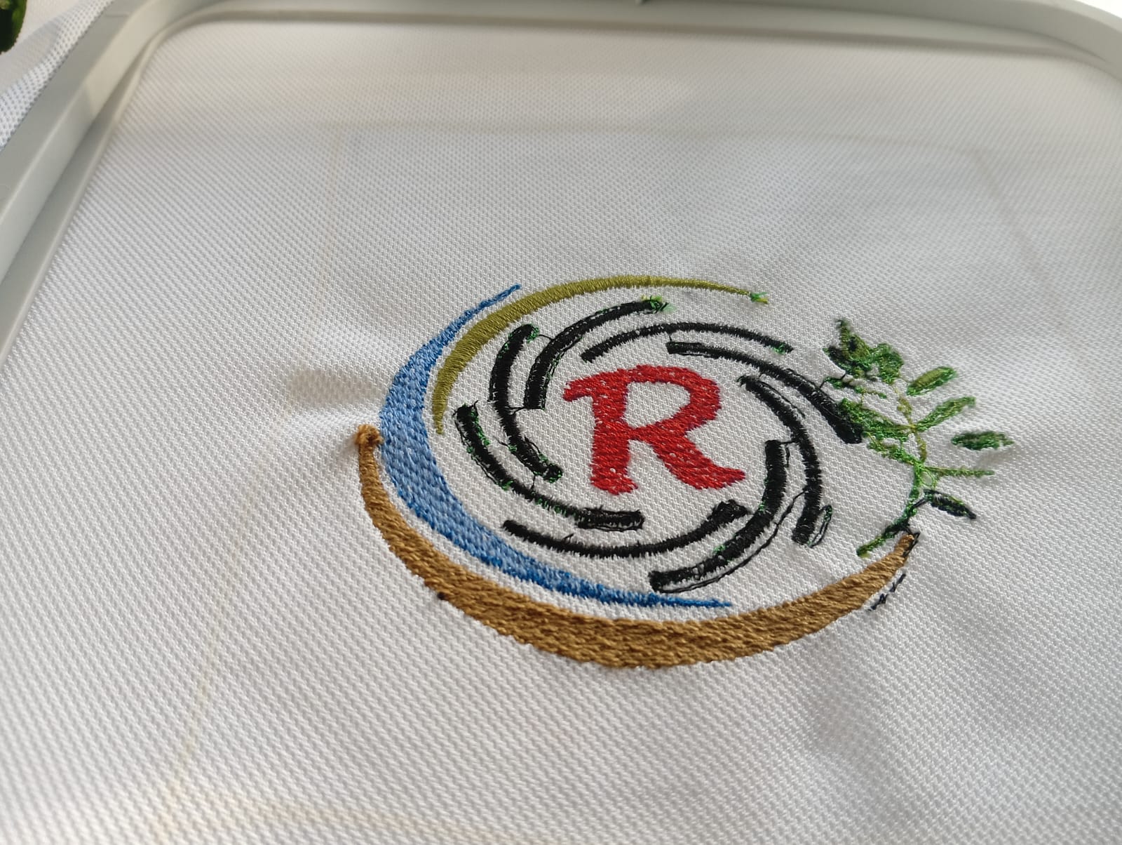
I added extra leaves and some outline designs to enhance the creativity. After making these additions, the logo looked much better. Below, I am showing the final design of my logo.
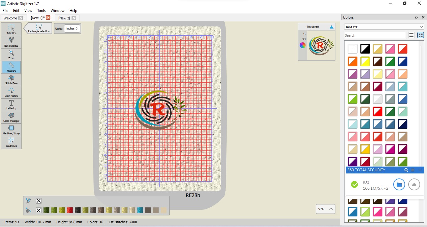
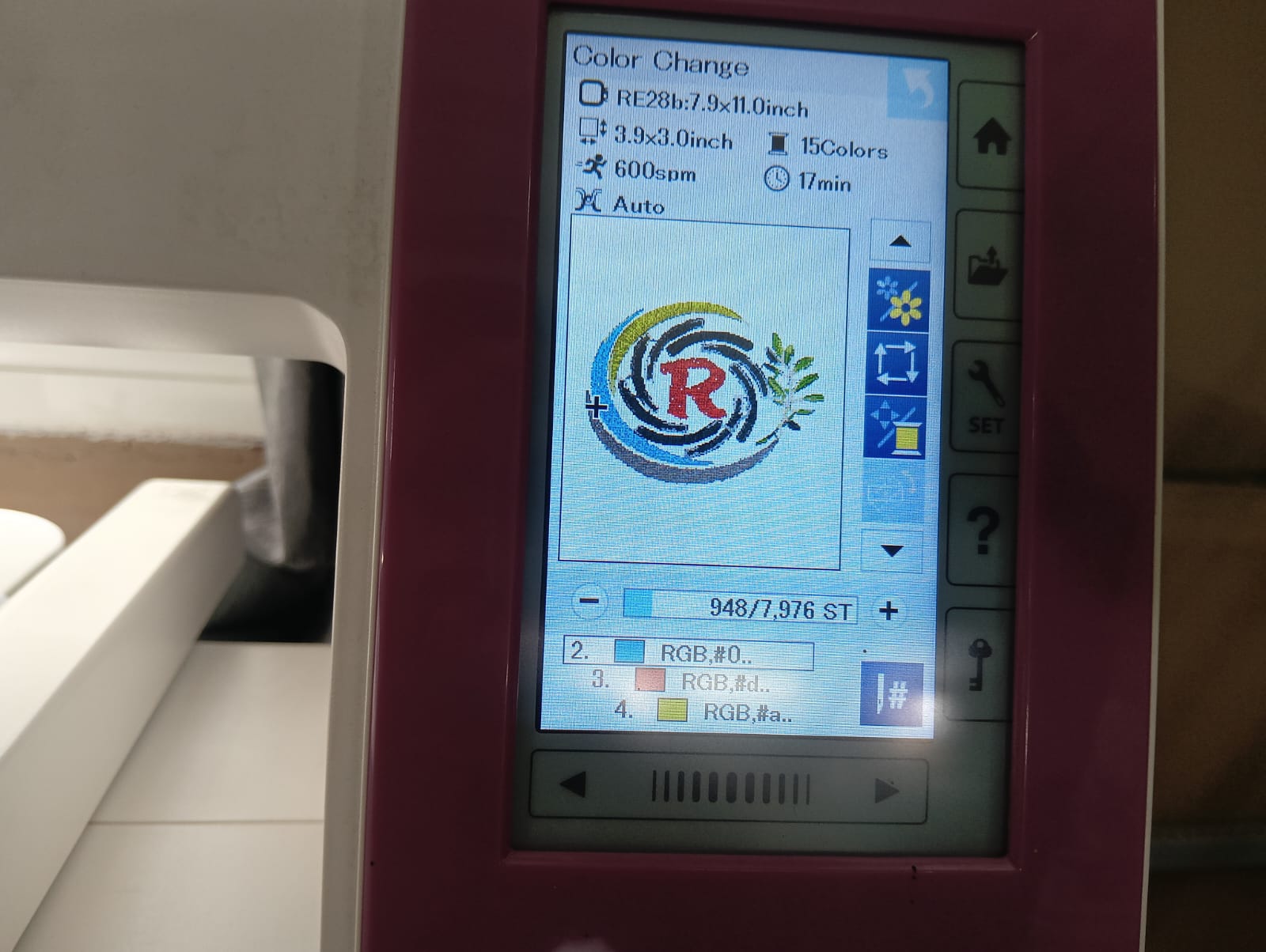
After that, I adjusted the height and width of the logo, and I also changed some of the colors based on the thread colors available in the lab.
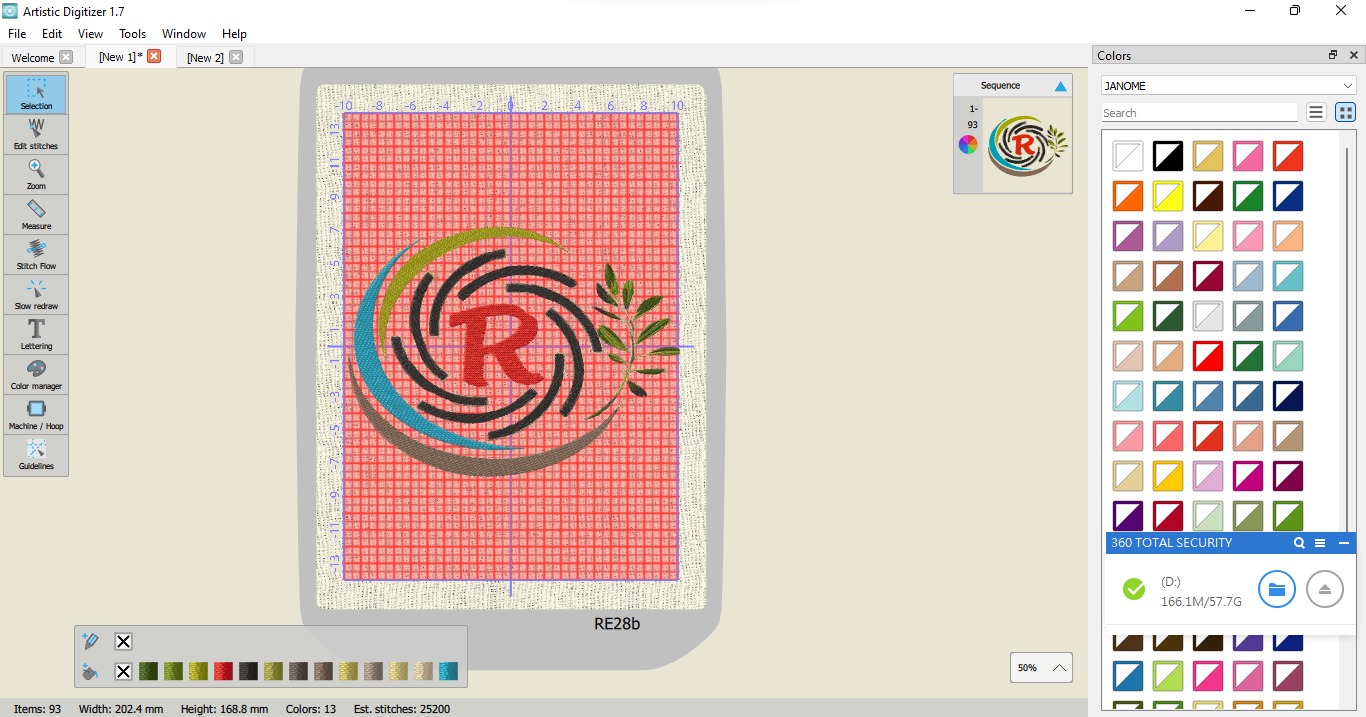
After that, I saved the updated embroidery code to the external drive and started stitching the logo using the Memory Craft 450E machine.
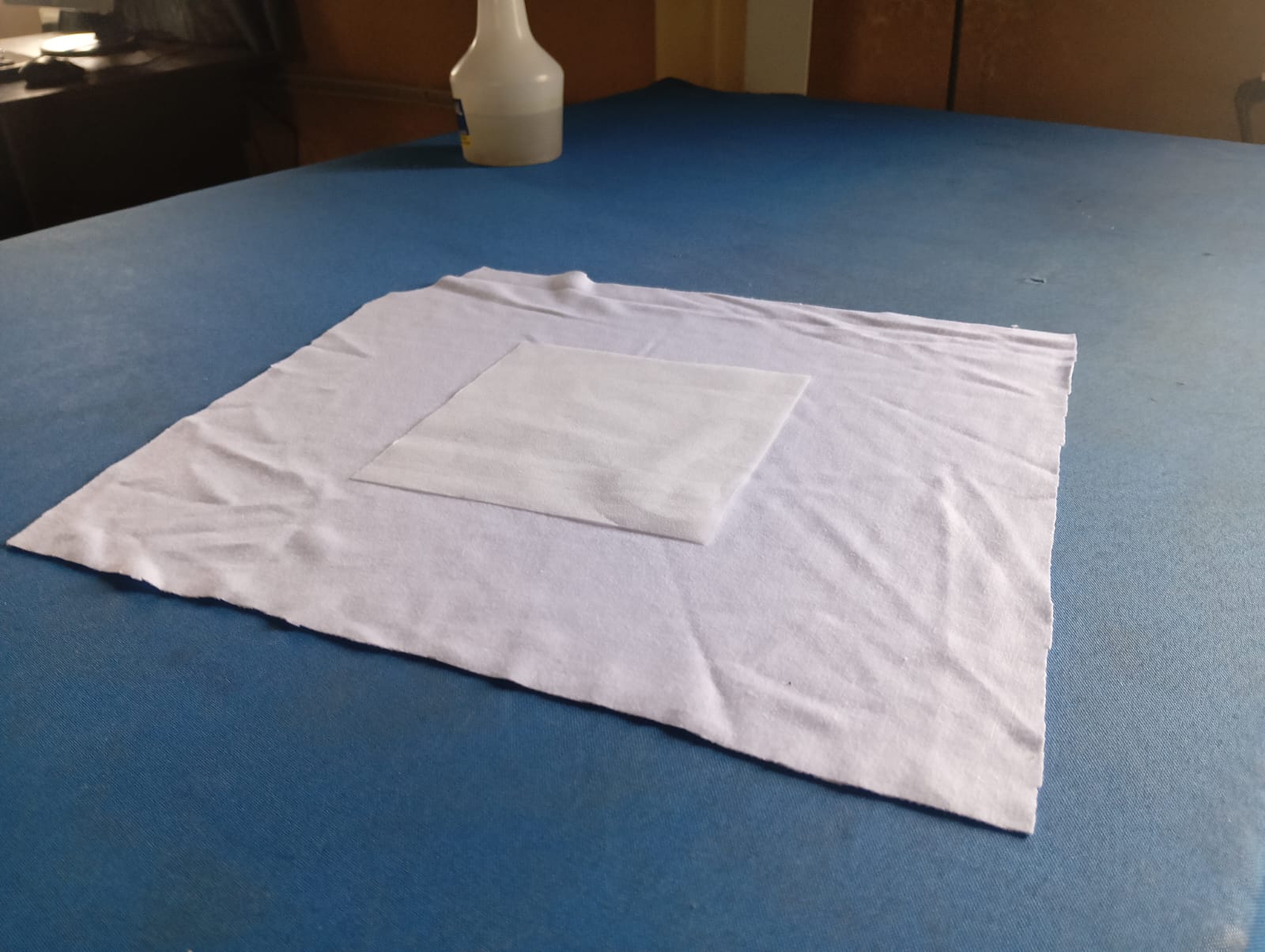
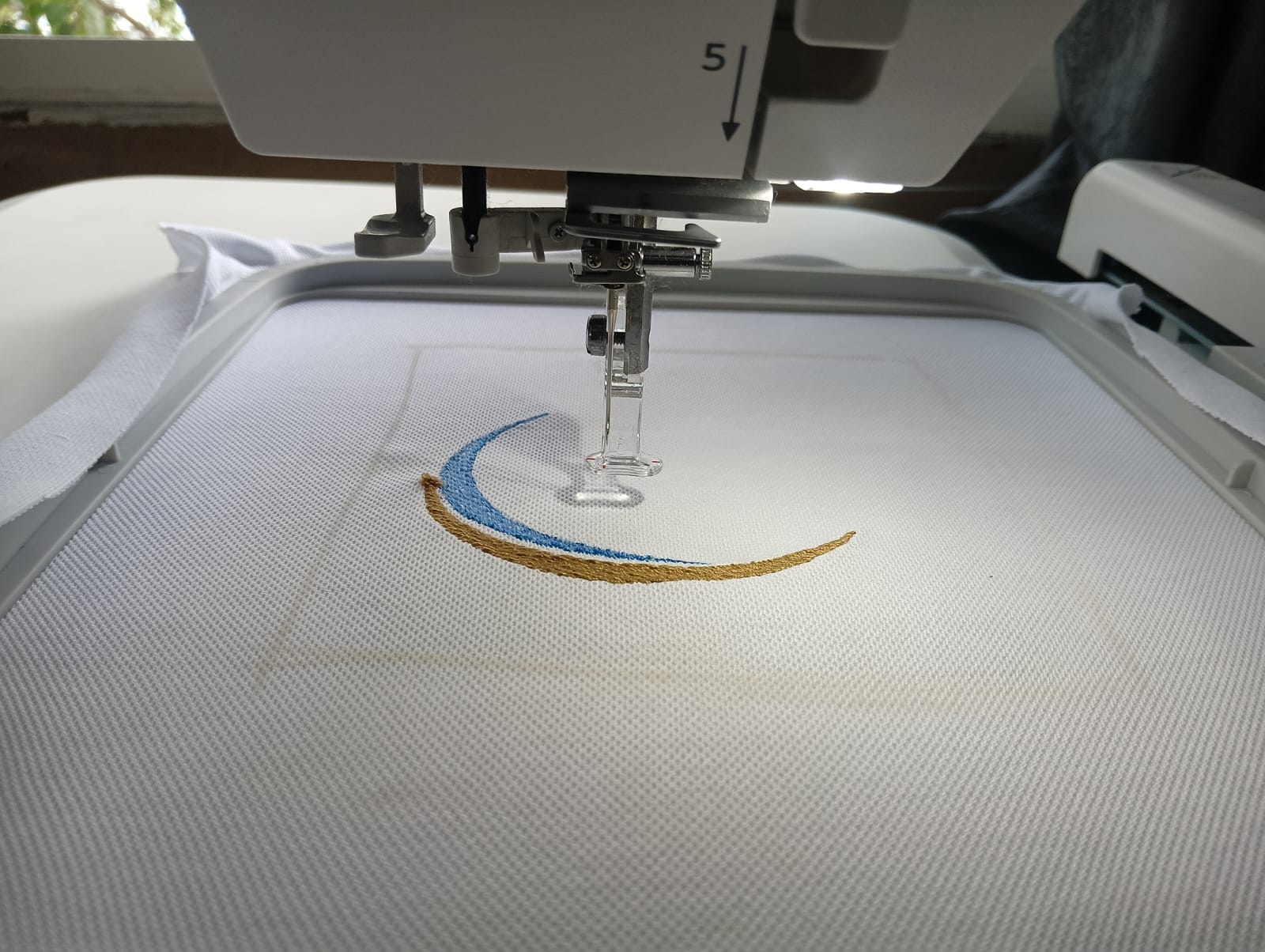
Before using the machine, I selected the fabric and attached a stabilizer sheet underneath it because the fabric was not suitable for direct embroidery. After that, I turned on the machine, selected my design, and started the embroidery process. Below, I am showing the results.
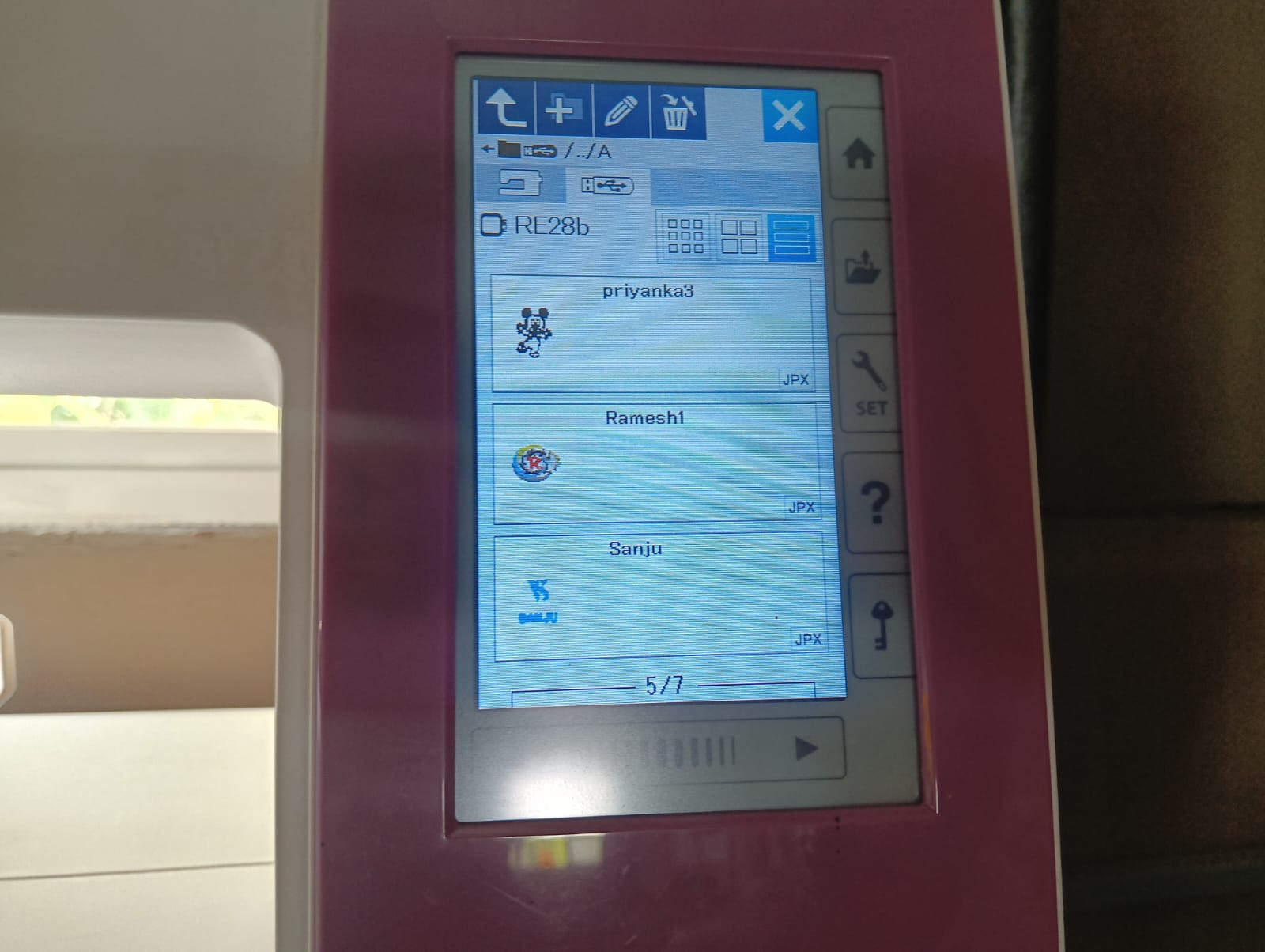
After that, I fixed the fabric to the machine. On the display, the machine showed which thread color to use. I followed the instructions provided by the machine step by step. The process is shown below.
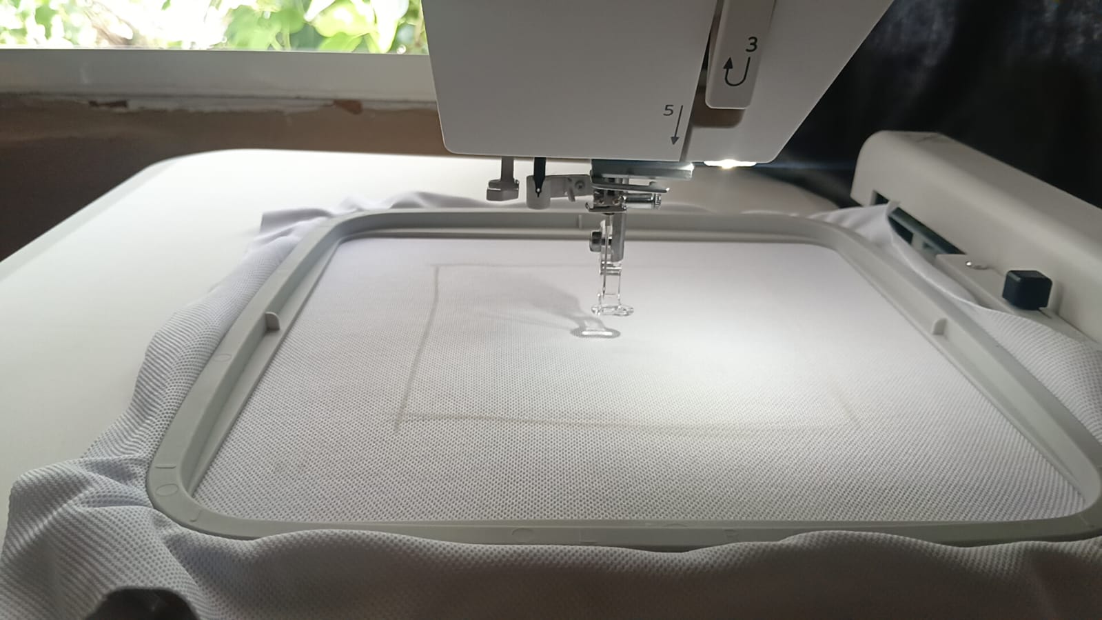
Below, I am showing how the machine is completing the logo stitching process.
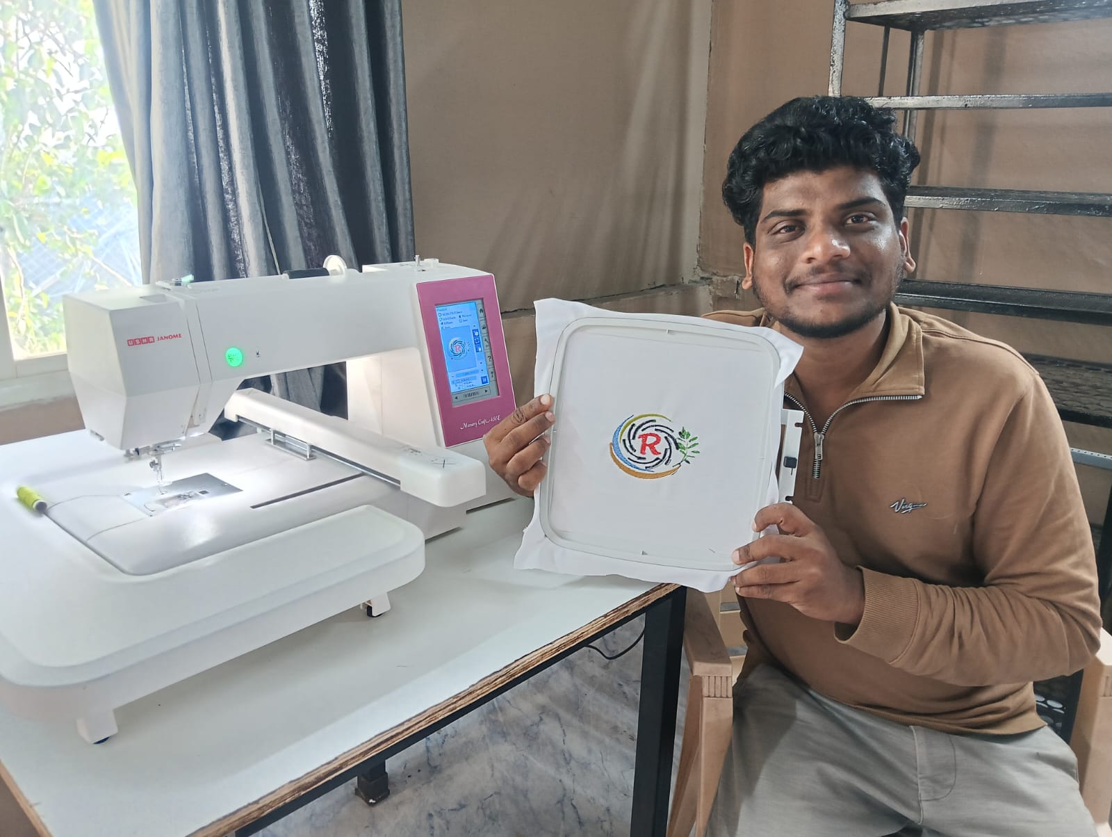
I am showing the final results below.
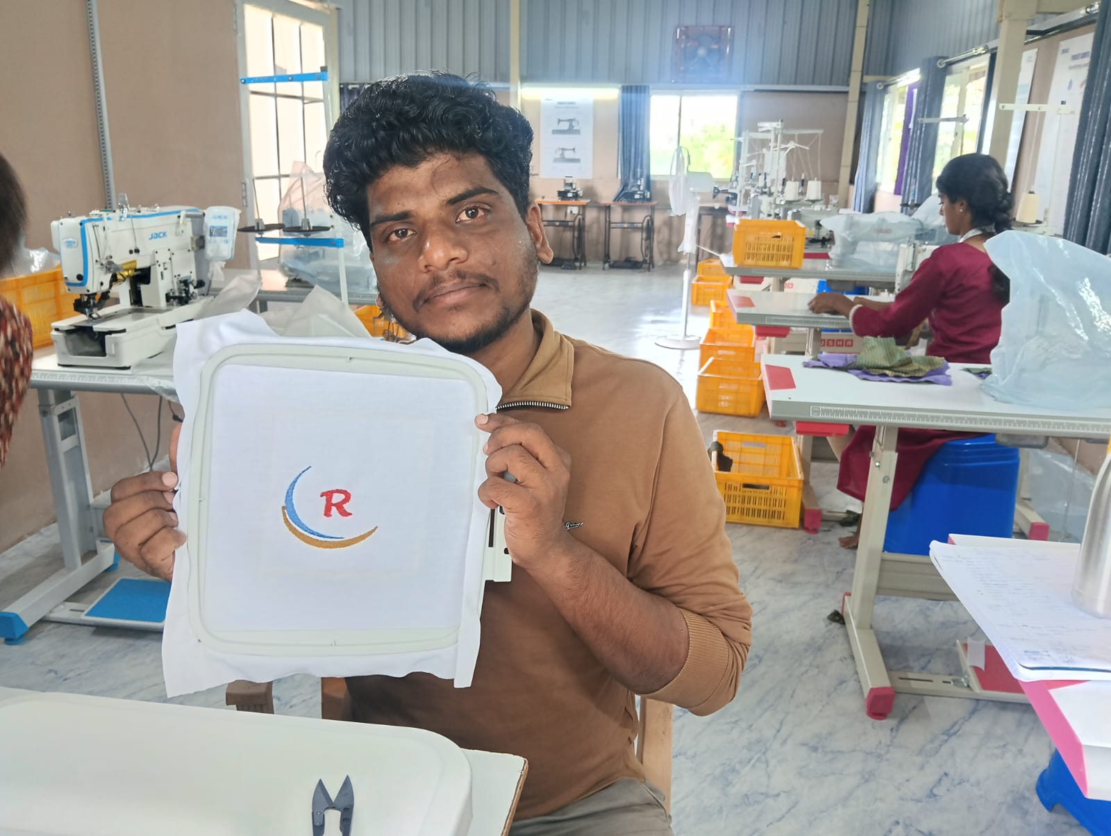
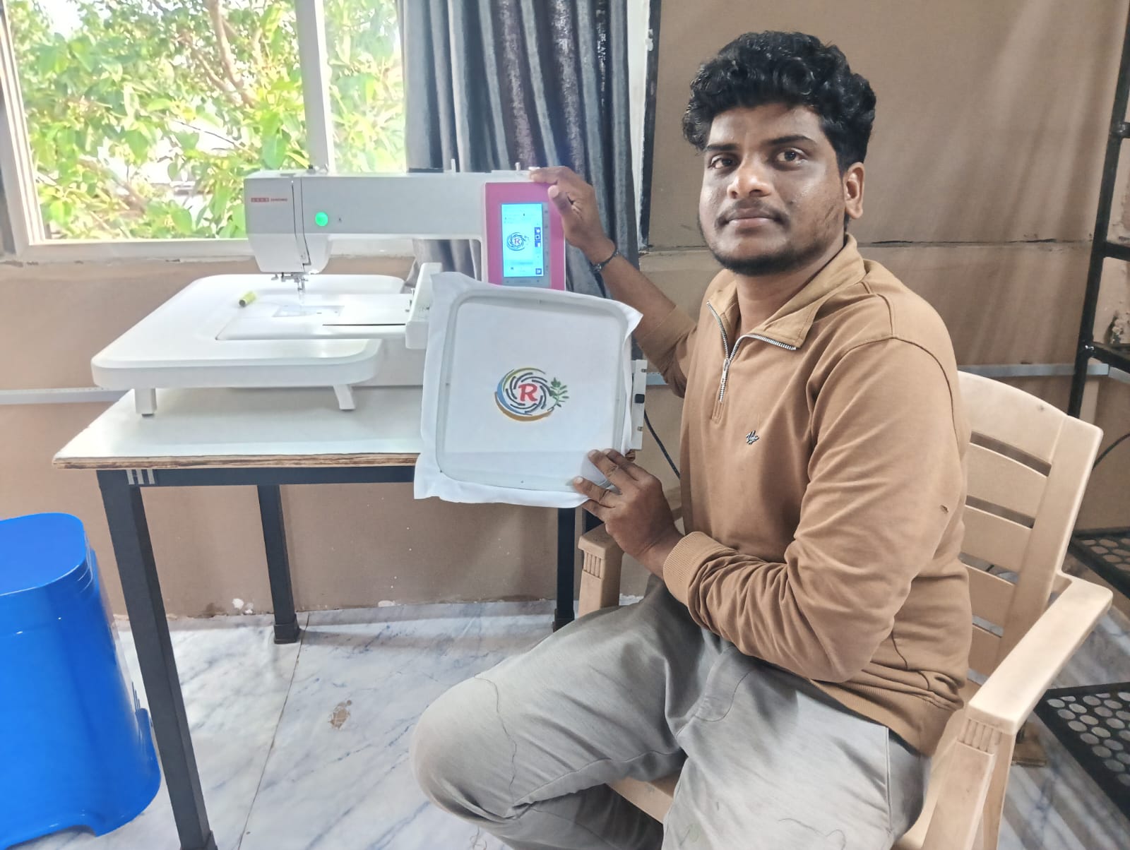
After completing all the steps, the logo was ready. It turned out very well, and I was happy with the final result.


Positive Outcomes:
In this assignment, I really enjoyed the process because I learned many new things. I explored sheet metal design in SolidWorks — something I had never done before. I not only designed the sheet metal part but also cut it using the plasma cutter. Even though I had no prior experience with the plasma cutting machine, I learned how to use it step by step from the basics.
Additionally, I had never operated an Embroidery Sewing Machine before, but through this assignment, I learned how to design logos using CorelDRAW and then stitch them using the sewing machine. I felt very happy seeing my logo come to life.
This assignment was completely new to me, but it was a great learning experience and I thoroughly enjoyed it.
Challenges Encountered:
This assignment was completely new to me, and I had never used a plasma cutter or embroidery sewing machine before. I faced several challenges during the process.
The first major challenge was related to design dimensions. Initially, I created my design in inches, but when I tried to generate the G-code in FastCAM, the design appeared very small. I later realized that FastCAM reads dimensions only in millimeters. Because of this, I had to redesign everything on another system using millimeters, which caused some delays.
Another challenge I faced was during the cutting process. While the plasma cutter was working, there was a sudden power cutoff. Unfortunately, the machine had no resume option, so I had to reposition the sheet and start the cutting again in a different area.
These were some of the main challenges I encountered, but I learned a lot by overcoming them.