Assignment 2: Computer-aided design
This week’s assignment focuses on documenting my learning in 2D and 3D computer-aided design, as well as exploring tools for image and video editing. I’ve been working on capturing my experience with raster and vector-based 2D design, 3D modeling, and the practical skills I’ve gained in resizing images and editing videos. Additionally, I’m reflecting on what went well, where I faced challenges, and how I can improve in future assignments.
2D design involves creating digital graphics and layouts, which can be categorized into two primary types: raster (pixel-based) and vector (geometry-based). Often, both approaches are combined to achieve a more polished result. Key components of 2D design include lines, shapes, colors, textures, and values. On the other hand, 3D design uses specialized software to create models that exist within three-dimensional space, defined by three coordinates that determine their position.
But why is 3D design so significant for designers: provides a powerful tool for tackling unique challenges and enhances visual communication. By incorporating 3D elements, designers can add depth, variety, and a sense of realism to their work. This is especially valuable in user experience (UX) design, where bridging the gap between digital and physical interactions is crucial for creating intuitive and relatable designs.
In addition to design tools, I’ve also recognized the importance of managing media efficiently for documentation. Throughout my Fab Academy journey, I’ll be generating a substantial number of images and videos. These files can quickly consume storage space, so resizing and editing them becomes essential. Moreover, learning video editing skills will enable me to present my work in a concise and impactful way, ensuring that my documentation is both effective and professional.
Overall, this assignment has allowed me to not only document my learning but also enhance my understanding of essential tools and techniques for design and documentation. The experience of working with different tools has inspired me to experiment more creatively and approach each assignment with a stronger focus on efficiency and presentation.
Highlight Moments of the Week
Raster 2D Design
2D design forms the foundation of many creative digital projects, involving the creation of visual content through elements like lines, shapes, colors, textures, and values. It can be categorized into two main types: **raster graphics** and **vector graphics**.
Raster graphics are composed of pixels, making them resolution-dependent. These images are ideal for detailed and complex visuals, such as photographs or intricate designs. However, because they are pixel-based, resizing raster images can result in a loss of quality, causing the visuals to appear blurry or pixelated. Common file formats for raster images include JPEG, PNG, and BMP.
While working with raster graphics, I’ve learned how to edit and manipulate images using software tools like Photoshop or GIMP. These tools allow adjustments to image properties, such as brightness, contrast, and sharpness, and enable creative edits like layering and masking. Resizing raster images is a key skill I’ve focused on, as it ensures that my work remains efficient in terms of storage and optimized for documentation.
GIMP and MyPaint are open-source programs, whereas Adobe Photoshop is a commercial software used for raster 2D design. For my practice, I specifically used Adobe Photoshop 2023.
Photoshop: 2D Raster Design Software
Adobe Photoshop is a powerful 2D raster design software widely used for photo editing, graphic design, and digital artwork. It allows for detailed manipulation of pixel-based images, offering tools for retouching, color correction, and creating intricate designs. With features like layers, masks, and filters, Photoshop is an essential tool for professionals in the design industry.I used photoshop to perform various operations to edit images.
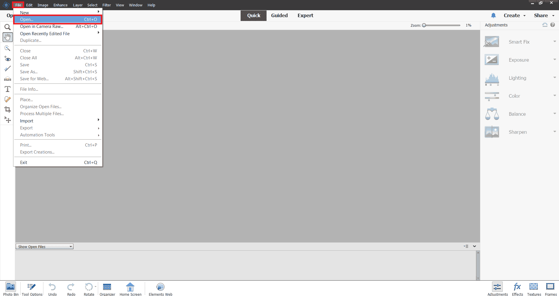
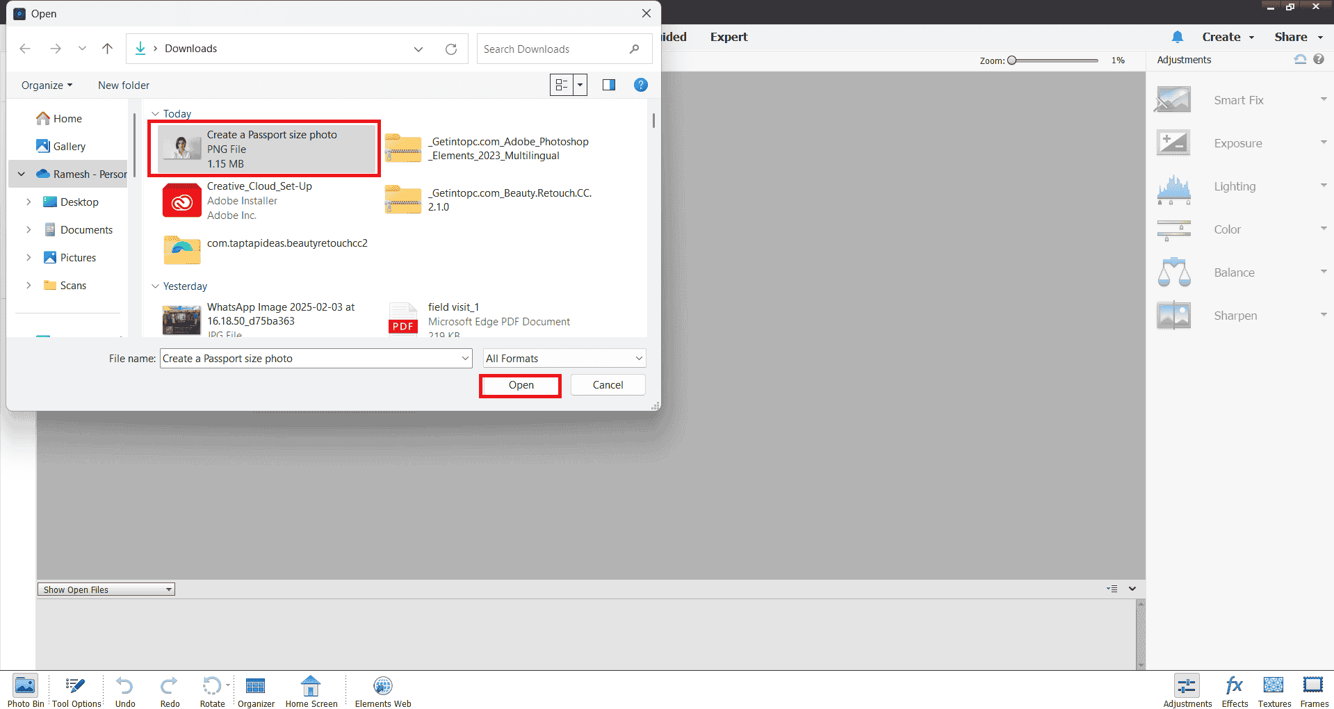
Step 1: I downloaded the image from Google and then imported it into Photoshop using the Open File option.
Step 2: My image was larger than the standard passport photo size, so I used the Crop Tool to adjust it. I set the width, height, and resolution to match passport photo requirements. Then, I dragged my mouse over the image to select the desired area.
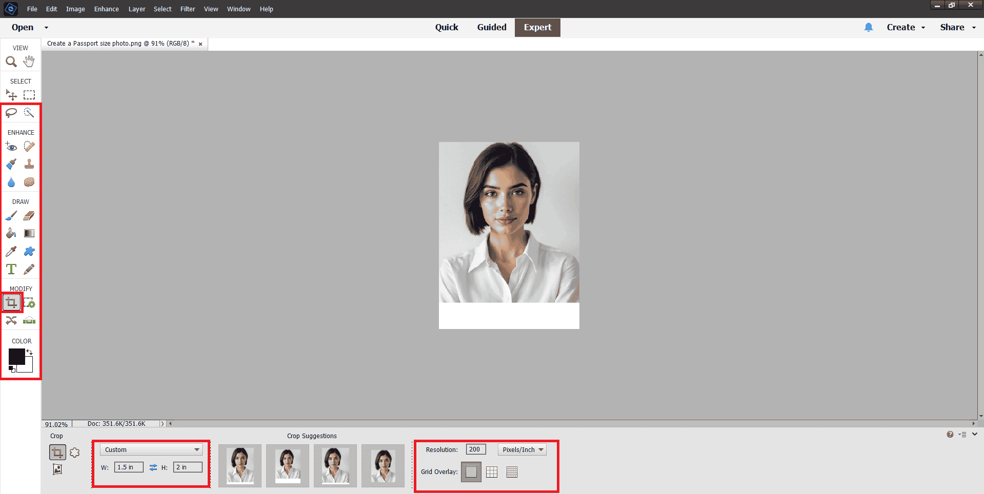
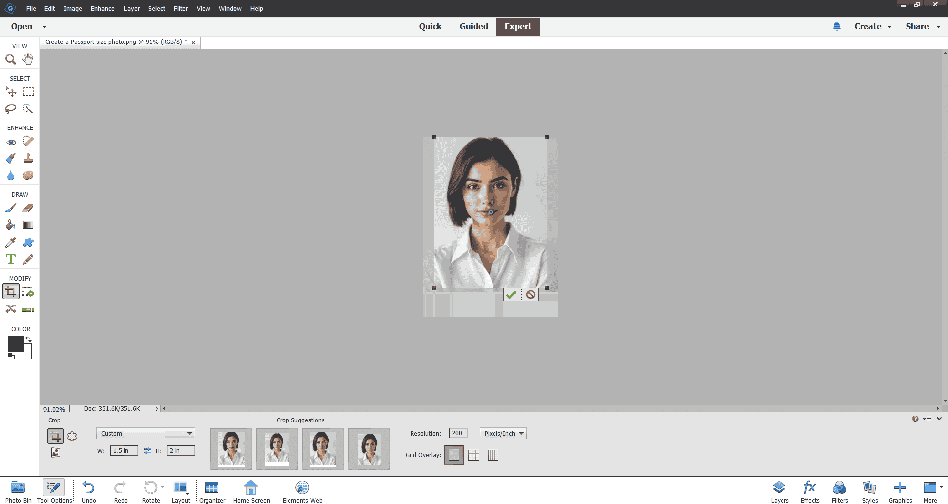
Step 3: I needed to add a border to my photo, so I selected the image using the shortcut key Ctrl + T. I adjusted the photo to fit the border requirements. Then, I went to the Edit menu, selected the Stroke option, set the border color, and chose a width of 5 pixels
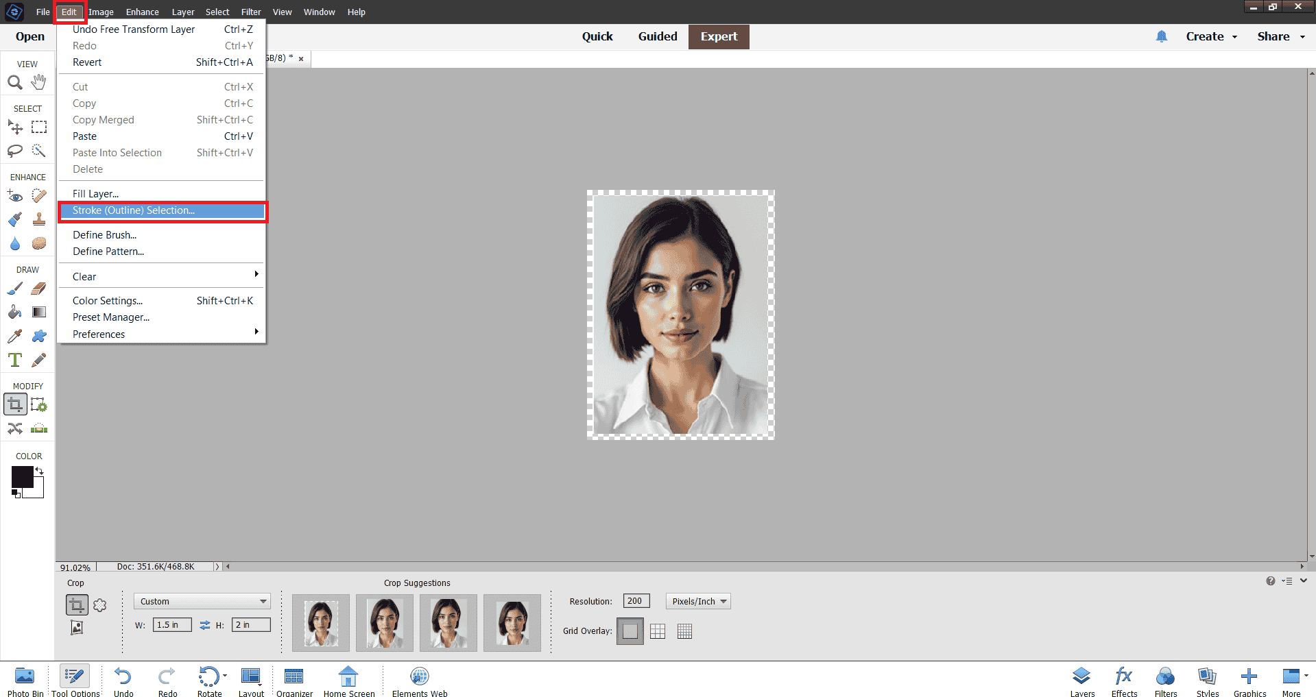
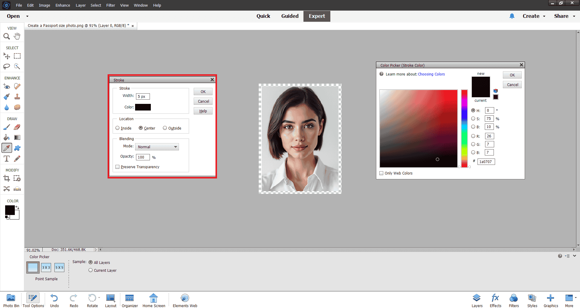
Step 4: I needed to add a border to my photo, so I selected the image using the shortcut key Ctrl + T. I adjusted the photo to fit the border requirements. Then, I went to the Edit menu, selected the Stroke option, set the border color, and chose a width of 5 pixels
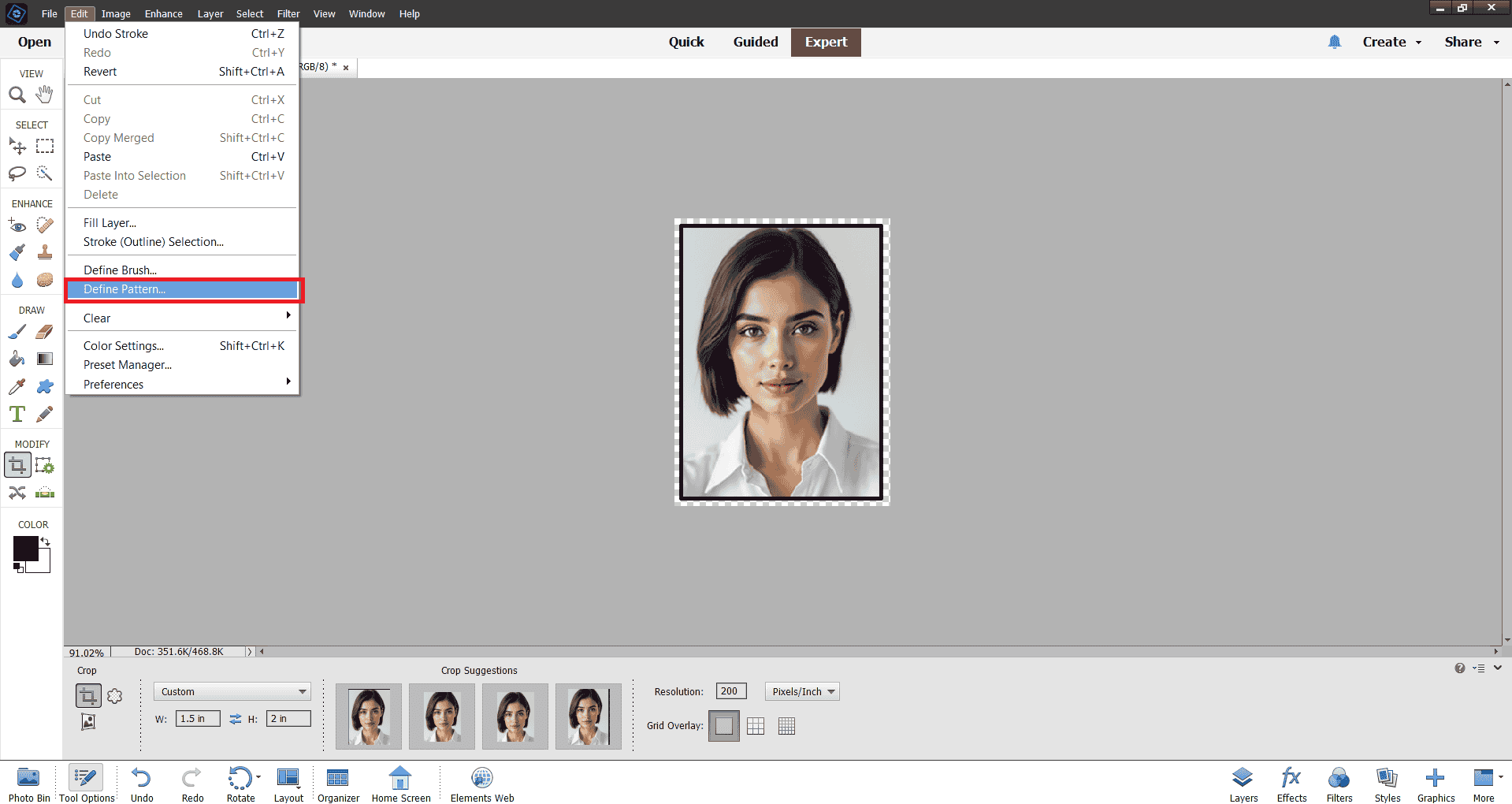
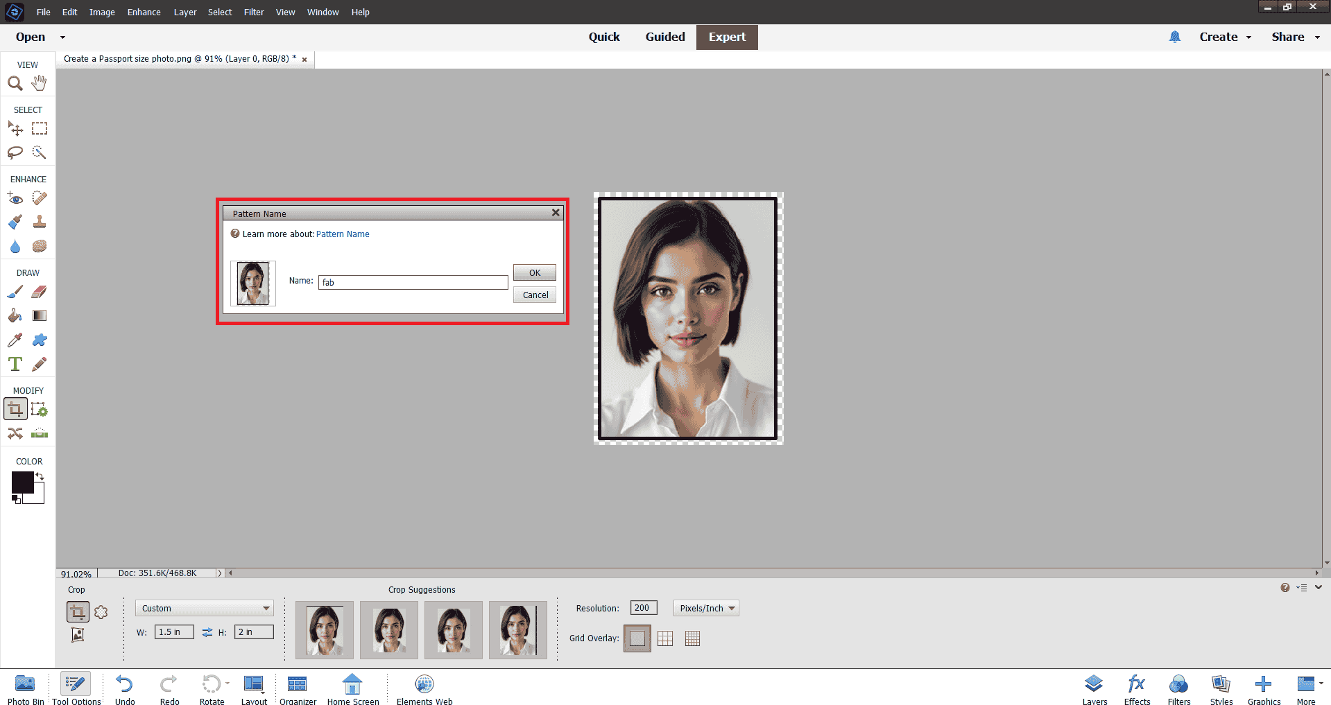
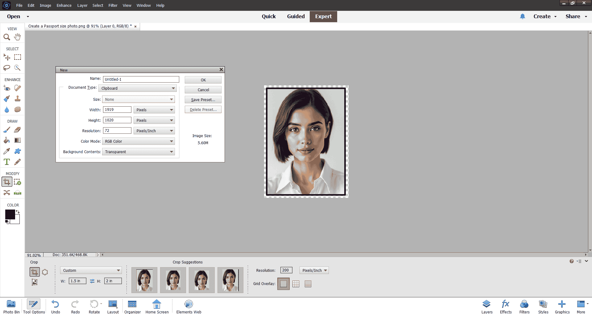
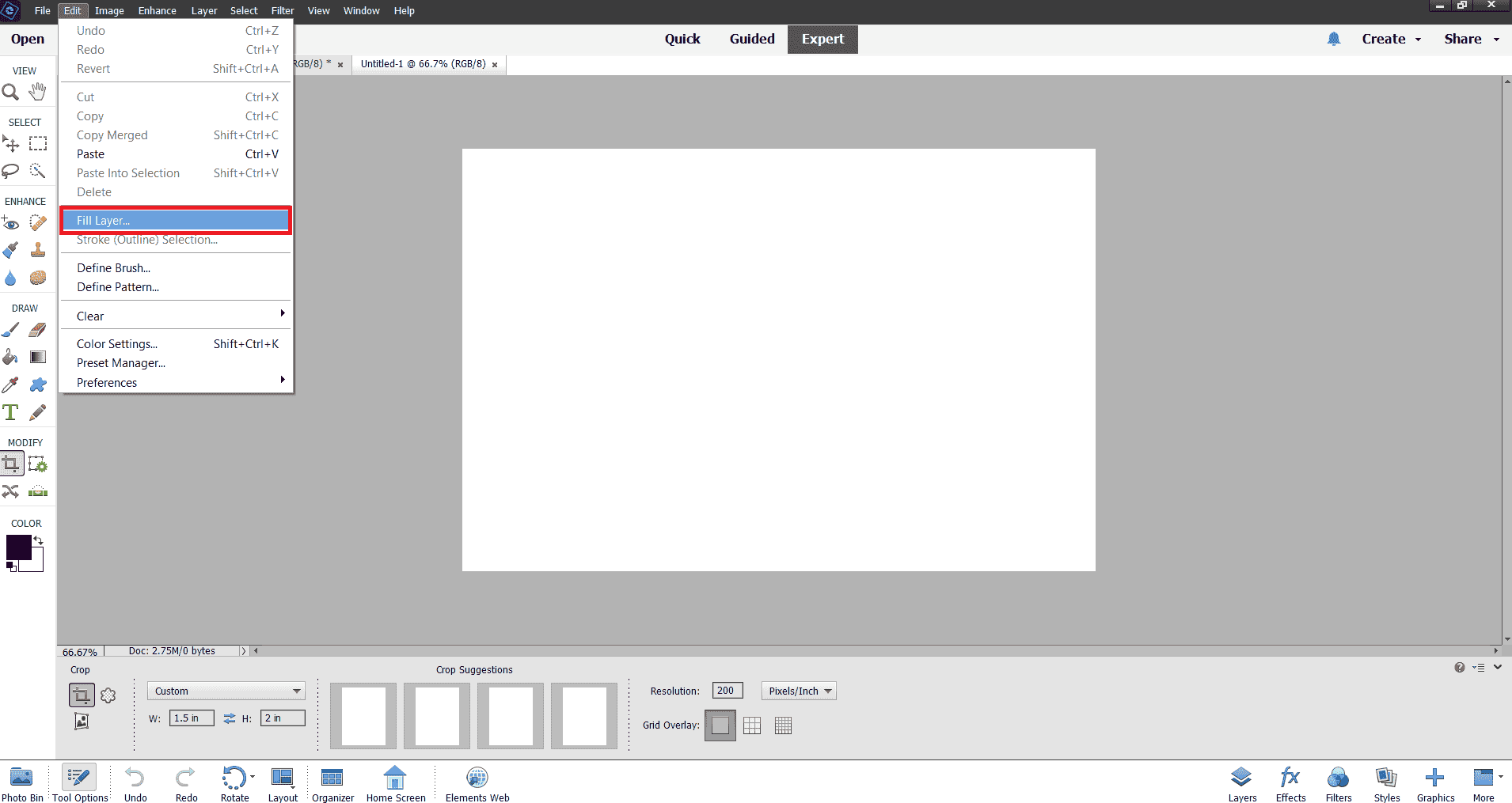
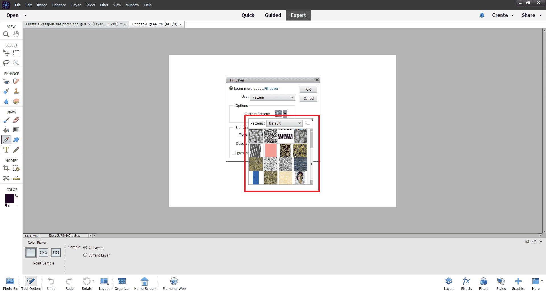
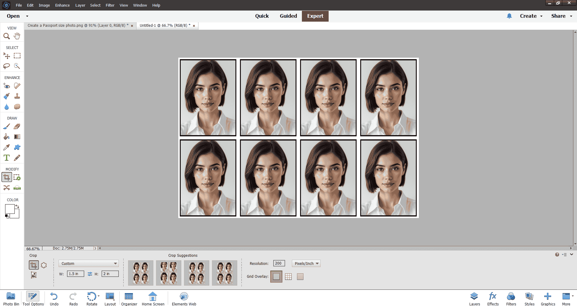
Step 5: After that, I created a new document for my 8 passport photos. I adjusted the width, height, resolution, and background color. Then, I went to the Edit menu, selected the Fill option, and chose my saved pattern to apply it.
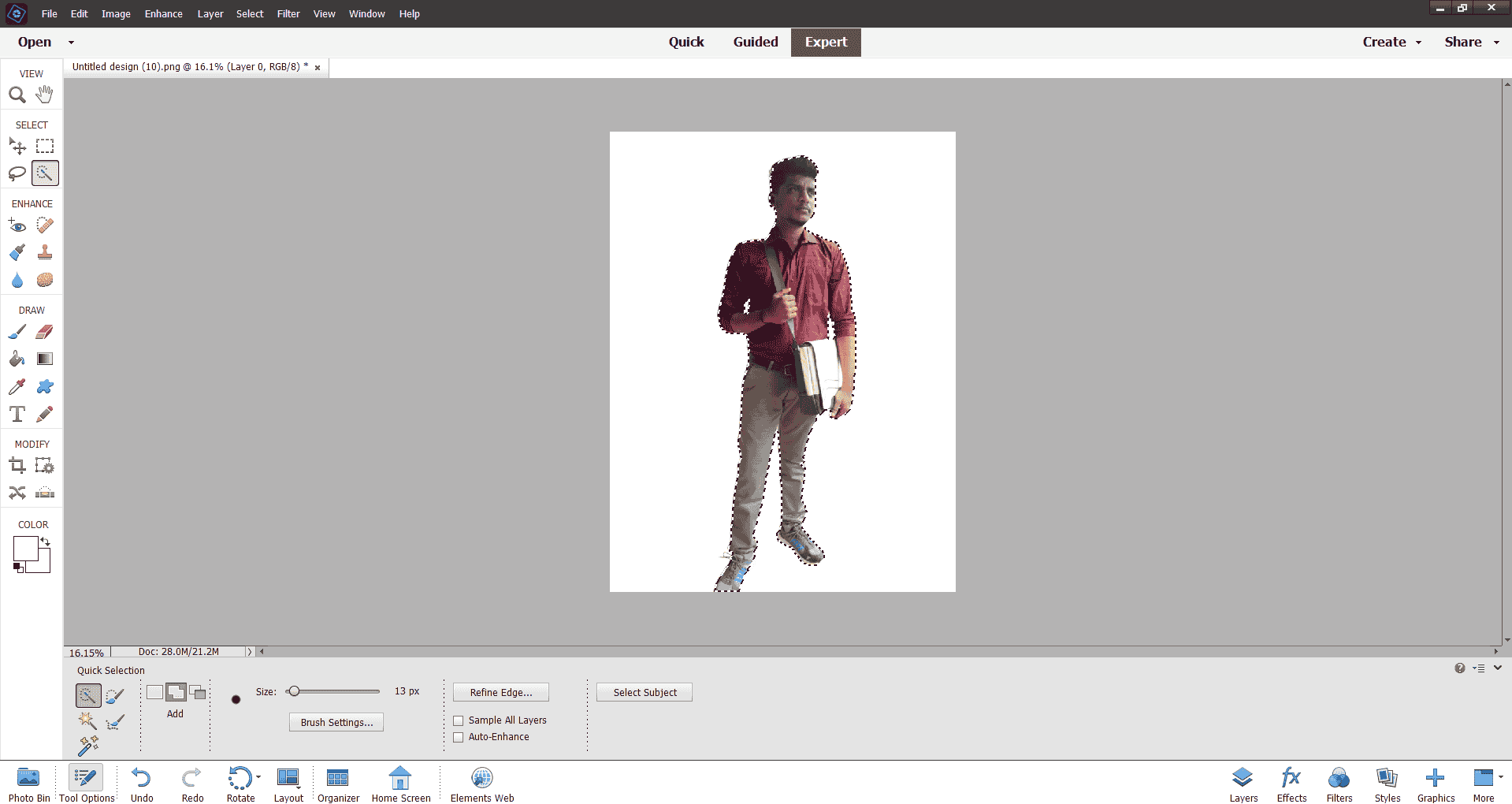
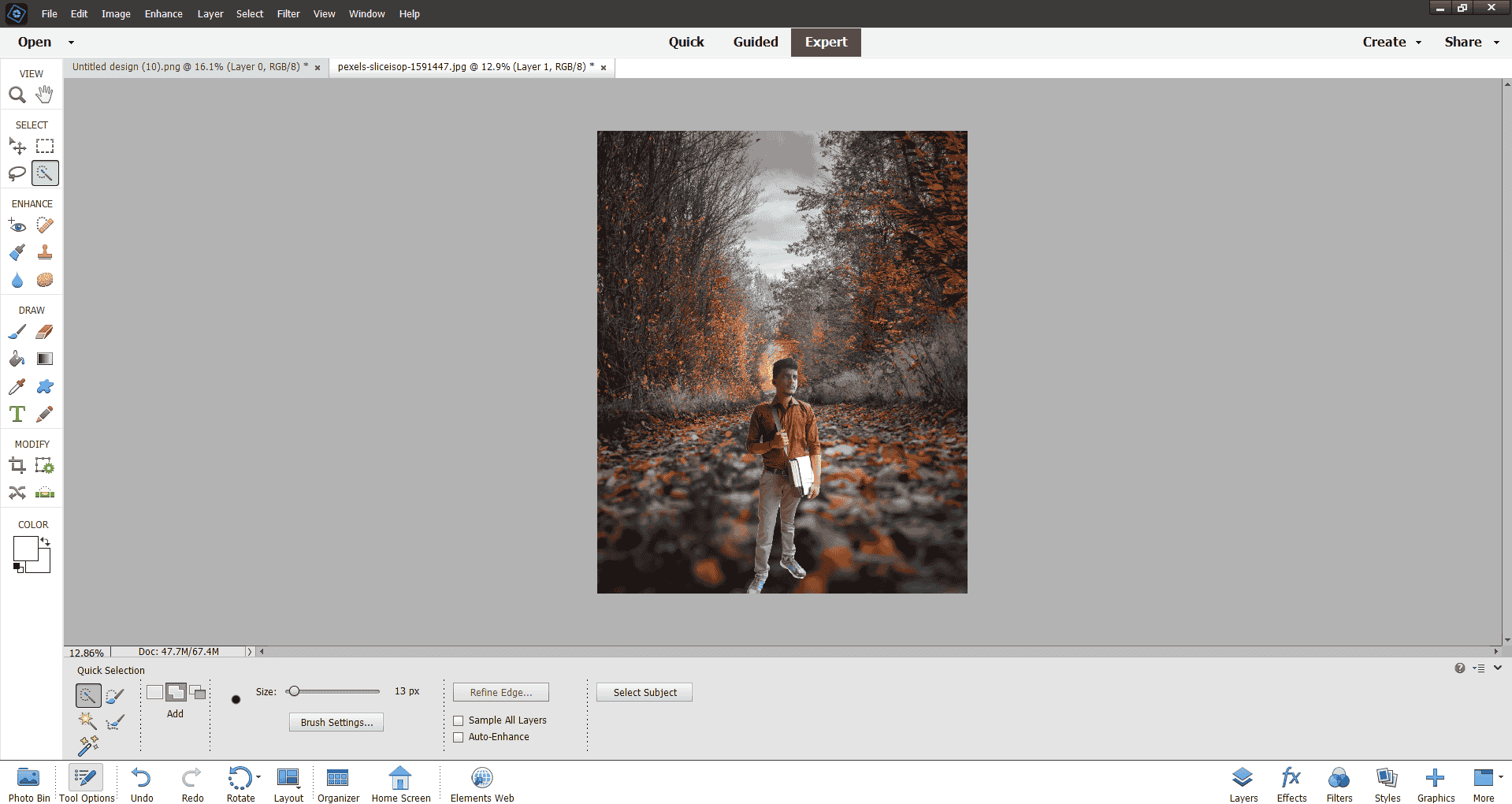
I also learned how to add a background image to my photo. I imported the background image into Photoshop, placed it behind my passport photo layer, and adjusted its size and position to fit properly.
Vector 2D Design
Vector 2D design involves creating digital graphics using mathematical equations to define shapes, lines, and curves. Unlike raster graphics, vector designs are resolution-independent, meaning they can be scaled to any size without losing quality. This makes them ideal for logos, illustrations, and designs that need to be resized frequently, such as billboards or business cards.
Vector graphics are typically created using software like Adobe Illustrator, Inkscape, and CorelDRAW. Key features of vector design include the use of paths, anchor points, and control handles to create precise shapes and smooth curves. These designs often rely on elements like fills, strokes, and gradients to add color and depth.
One major advantage of vector design is its small file size compared to high-resolution raster images, as it only stores data about shapes and their properties. However, vector graphics are not suitable for creating detailed images like photographs, as they lack the pixel-level detail found in raster images.
Overall, vector 2D design is essential for projects requiring high scalability and precision, making it a preferred choice for graphic designers and illustrators.
Inkscape and Sketchpad are examples of open-source software, while Illustrator and CorelDRAW are commercial tools commonly used for vector 2D design. For my practice, I used Inkscape to explore and create scalable vector graphics.
INKSCAPE: 2D Vector Design Software:
Inkscape is a versatile open-source 2D vector design software widely used for creating scalable graphics such as logos, illustrations, and diagrams. It offers powerful tools for drawing, editing paths, adding gradients, and applying transformations, making it a great alternative to commercial vector tools. Inkscape supports SVG (Scalable Vector Graphics) as its native file format, ensuring compatibility with other design tools. Its user-friendly interface and extensive features make it an excellent choice for both beginners and professionals working on vector-based projects.
From this interface in **Inkscape** , I can observe and learn various tools essential for vector design. The **Toolbar** on the left introduces us to tools for drawing shapes, creating paths, and adding text, while the **Menu Bar** at the top provides access to features like layers, filters, and object transformations. The **Trace Bitmap** panel on the right is particularly useful for learning how to convert raster images into vectors by adjusting settings like threshold, smooth corners, and speckles. Additionally, the **Color Palette** at the bottom helps in quickly applying fills and strokes, and the central **Canvas** is where we practice creating and editing vector designs. Exploring these tools allows us to understand the fundamentals of vector graphics and optimize workflows effectively.
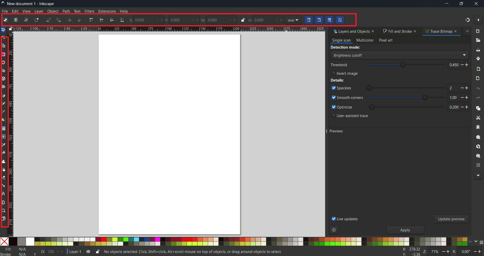
Next create this design, I started by importing a low-resolution image into Inkscape. I then navigated to the Path > Trace Bitmap tool to convert the raster image into a vector graphic. By carefully adjusting the threshold value and fine-tuning parameters such as speckles, smooth corners, and optimization, I achieved the desired level of detail and sharpness. Finally, the image was successfully converted into a clean and scalable vector design, demonstrating the power of vectorization for enhancing low-resolution graphics.
3D Design
3D Design is the process of creating three-dimensional objects or models using computer-aided design (CAD) software. Unlike 2D design, which focuses solely on flat images, 3D design incorporates three axes—X (width), Y (height), and Z (depth)—to create objects with realistic dimensions and spatial depth. This allows designs to be visualized and manipulated from multiple angles, making them ideal for a wide range of industries such as architecture, product design, animation, and engineering.The primary advantage of 3D design lies in its ability to bring concepts to life before physical production. Designers can create prototypes, simulate real-world performance, and test ideas virtually, saving time and resources. These designs can be rendered into photorealistic images, animated for dynamic visualization, or 3D printed for prototyping and manufacturing. The versatility of 3D design makes it a powerful tool for tackling complex design challenges and improving the overall efficiency of the creative process.
There are several popular tools available for 3D design, catering to various levels of expertise and applications. For beginners, software like Tinkercad provides an easy-to-use interface, while more advanced tools like Blender, Fusion 360, and SolidWorks offer robust features for professional-grade modeling and rendering. Each software is tailored to specific needs, from designing consumer products to creating detailed mechanical parts or stunning visual effects.
Mastering 3D design opens up endless possibilities for innovation and creativity. It allows designers to produce detailed, interactive models, solve complex design problems, and present projects in an engaging and immersive way. With its broad range of applications and impact, 3D design is an indispensable skill in modern design and manufacturing workflows.
Tinkercad and Onshape are web-based 3D modeling applications that offer free access for educational purposes. Similarly, SketchUp provides a free web-based 3D modeling platform accessible to everyone, alongside its paid desktop version. For desktop applications, FreeCAD and OpenSCAD are open-source options, while SolidWorks, Autodesk Fusion 360, CATIA, and Creo Parametric are commercial software solutions used for 3D design. In my practice, I utilized thinercad,FreeCAD and SolidWorks to develop my 3D modeling skills.

TINKERCAD:3D Design Software
Tinkercad is a free, web-based 3D modeling application developed by Autodesk, designed to make 3D design accessible to users of all levels. Its intuitive interface allows users to create complex models by combining simple geometric shapes, making it particularly suitable for beginners and educational purposes. Beyond 3D modeling, Tinkercad offers features for electronics and coding projects, providing a comprehensive platform for STEM learning. Users can design circuits, simulate Arduino microcontrollers, and even export models for 3D printing or integration into games like Minecraft. As a browser-based tool, Tinkercad requires no installation, enabling easy access across various devices. Its blend of simplicity and functionality has made it a popular choice among educators, students, and hobbyists exploring the realms of 3D design and electronics.At the beginning of my career, I embarked on my journey into 3D design using Tinkercad, a user-friendly, web-based application developed by Autodesk. Its intuitive interface allowed me to grasp the fundamentals of 3D modeling with ease. I engaged in numerous projects, ranging from simple geometric designs to more complex structures, which helped me build a solid foundation in 3D design principles. Tinkercad's accessibility and comprehensive tutorials enabled me to experiment freely and refine my skills, laying the groundwork for more advanced modeling endeavors in the future.
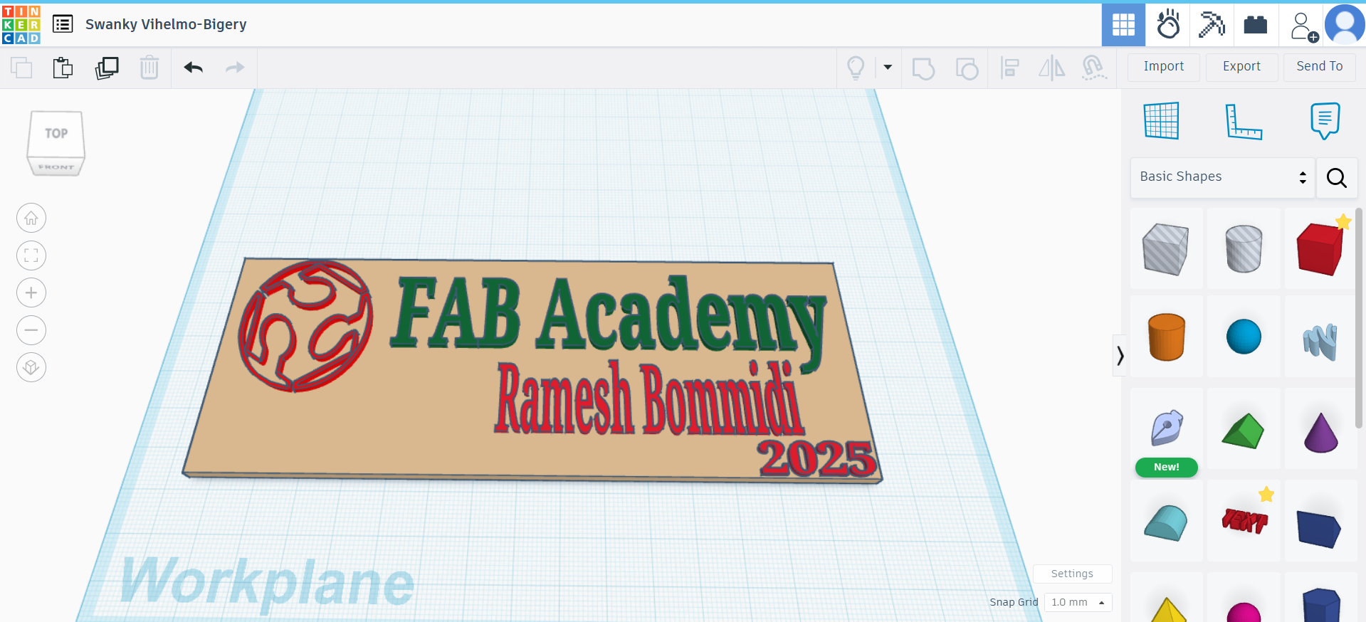
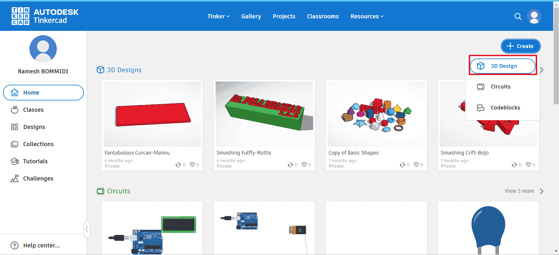
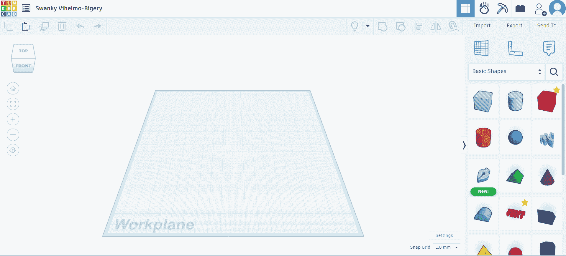
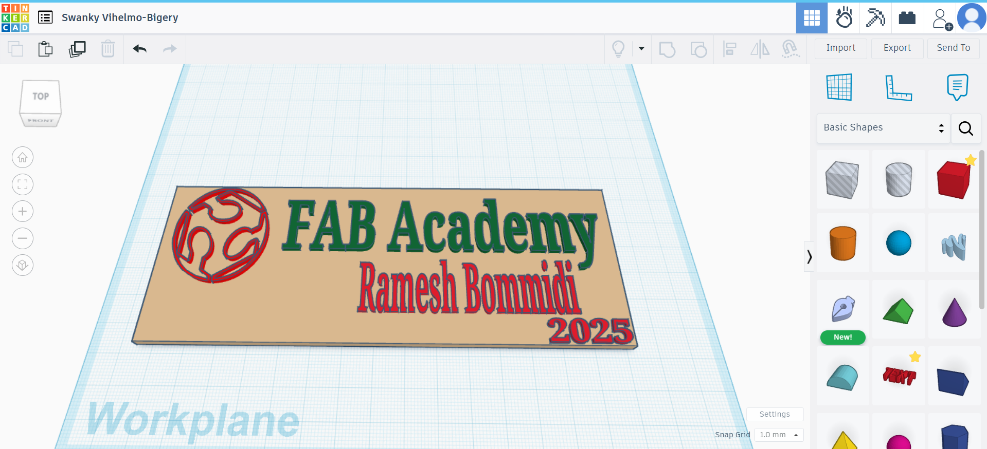
first, my 3D design in thinkarcad, I launched my web browser and navigated to Tinkercad's website. After creating an account, I initiated a new project by clicking on the "Create new design" button. This action opened up a fresh workspace, featuring a light blue 3D grid known as the Workplane, where I could start crafting my designs.
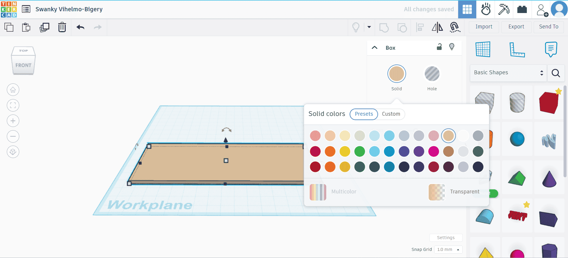
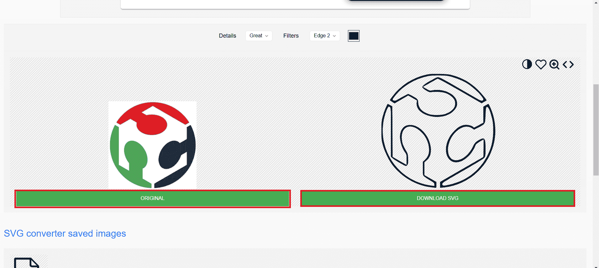
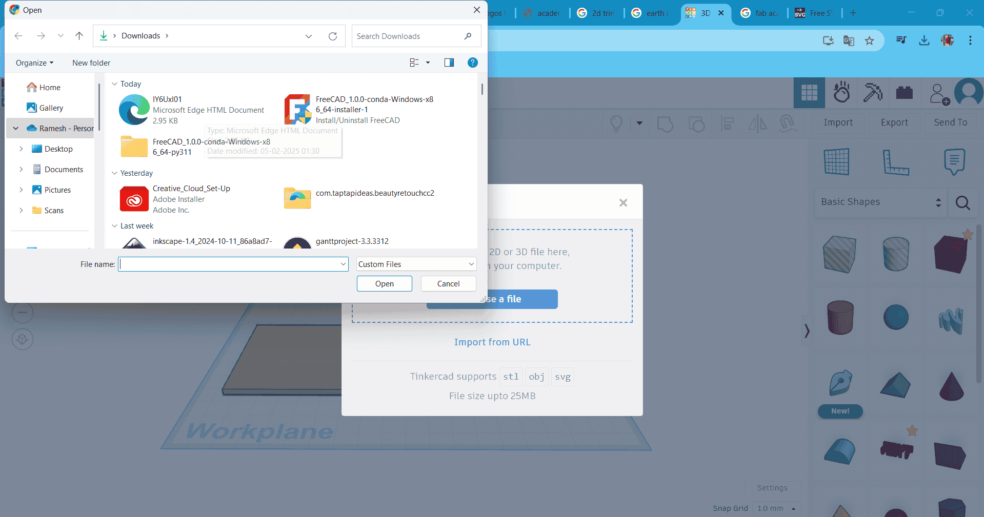
Next, I proceeded to create a base plate for my name board. I selected a cube from Tinkercad's geometric shapes library and adjusted its dimensions to meet my specific requirements, ensuring it would serve as a sturdy foundation. To personalize the design further, I decided to incorporate the Fab Academy logo. I downloaded the logo from the internet and converted it from a PNG to an SVG format using an online converter, as Tinkercad supports SVG files for importing custom graphics. After obtaining the SVG file, I imported it into my Tinkercad workspace, ready to integrate it into my base plate design.
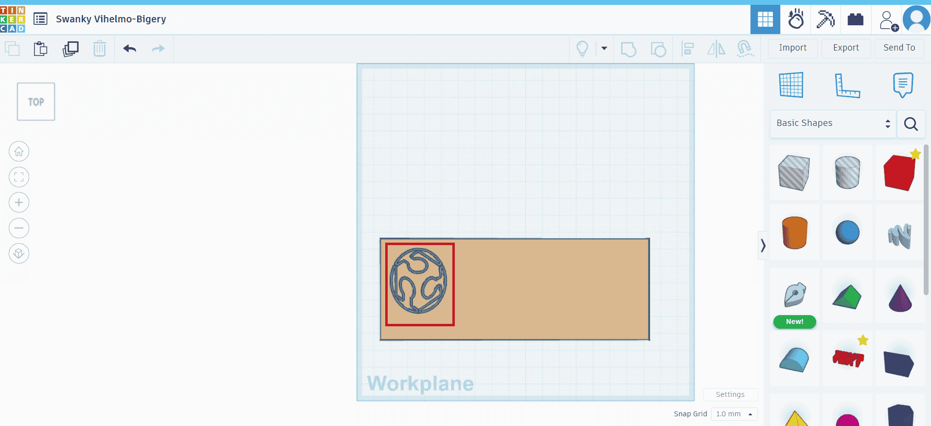
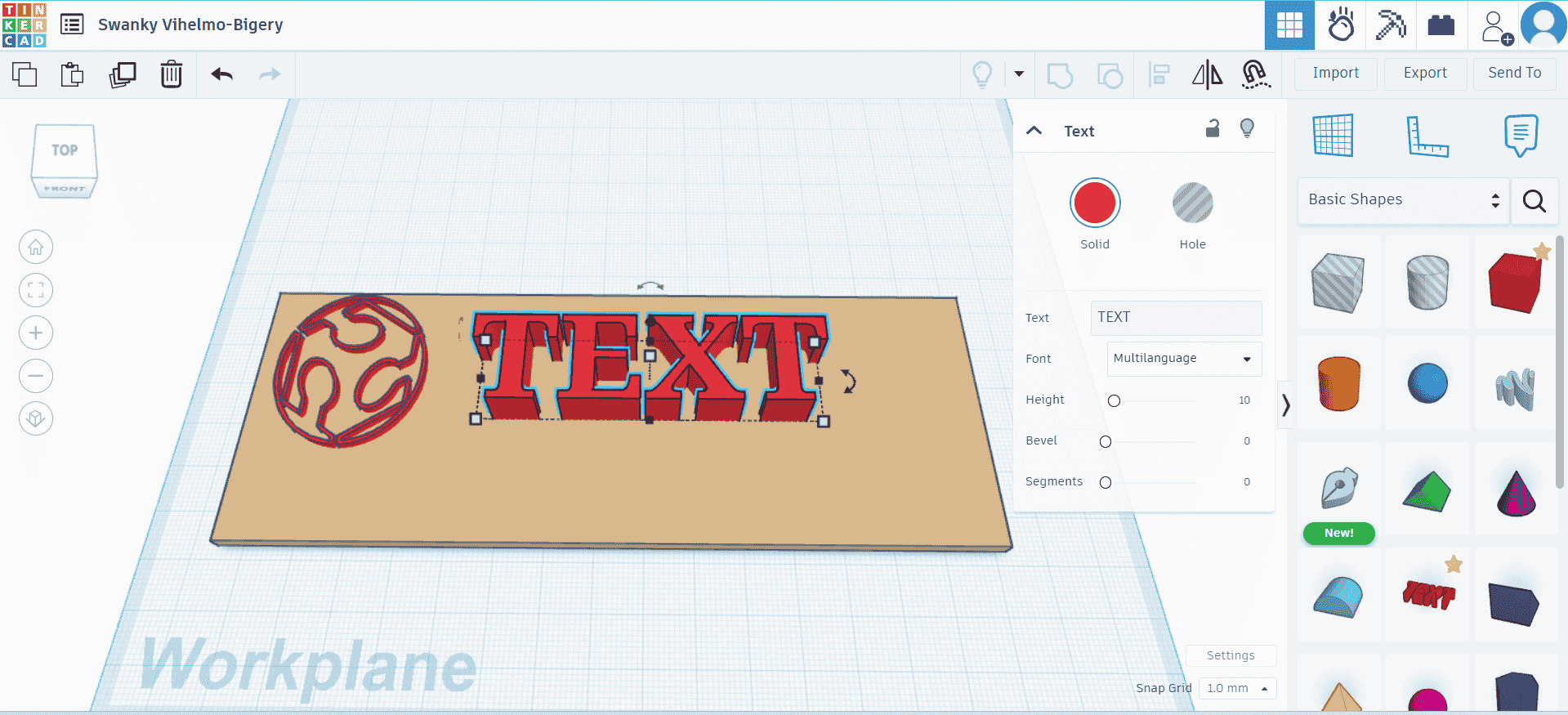
After, entering text using the text box option, I ensure it meets the given requirements. Finally, I download the STL file to print my nameplate.
FreeCAD: 3D Design Software:
FreeCAD is a powerful open-source 3D design software used for parametric modeling, allowing users to create and modify 3D objects by defining constraints and dimensions. It is widely used in engineering, product design, architecture, and even hobbyist projects like 3D printing. One of its key strengths is its modular architecture, which provides specialized workbenches for tasks such as part design, drafting, assembly, and simulation. FreeCAD supports various file formats, including STL, STEP, IGES, and DXF, making it compatible with other CAD software and 3D printing workflows. Additionally, it features a robust Python API, enabling automation, scripting, and customization to enhance functionality. As a free and open-source alternative to commercial CAD software, FreeCAD is continuously improved by a dedicated community, making it an excellent choice for both beginners and professionals looking for a flexible and accessible 3D modeling tool.
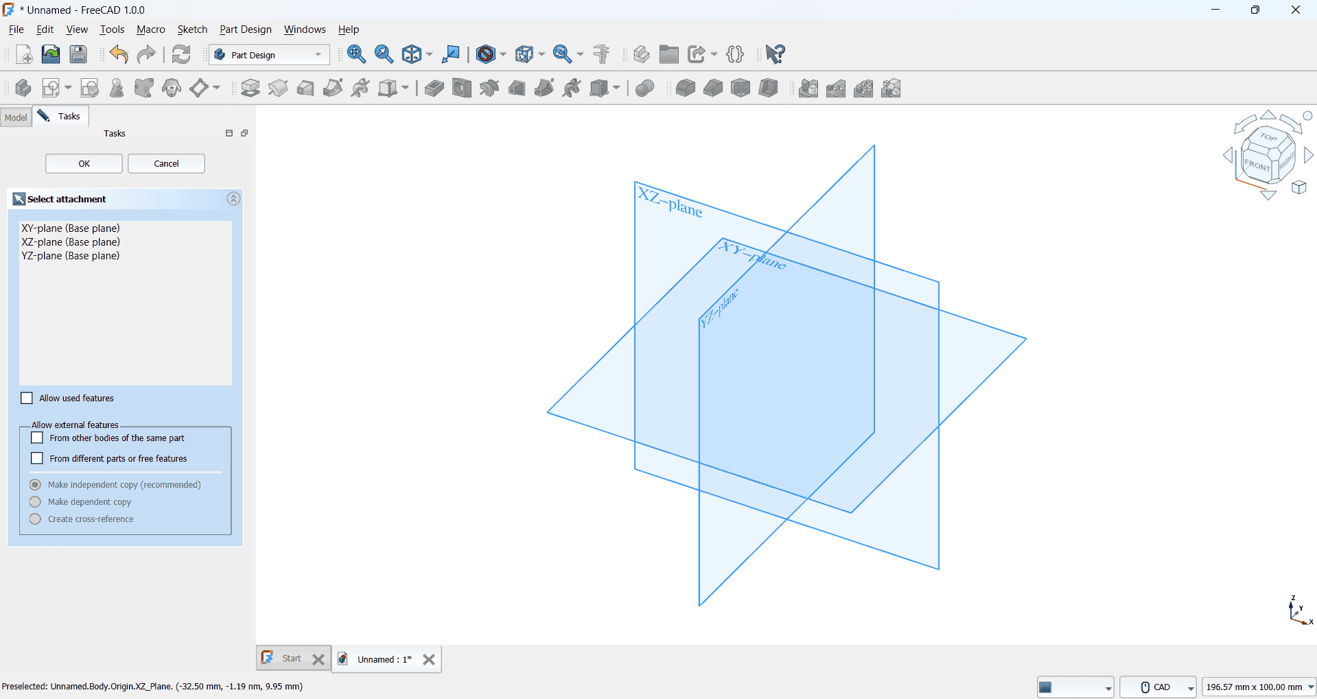
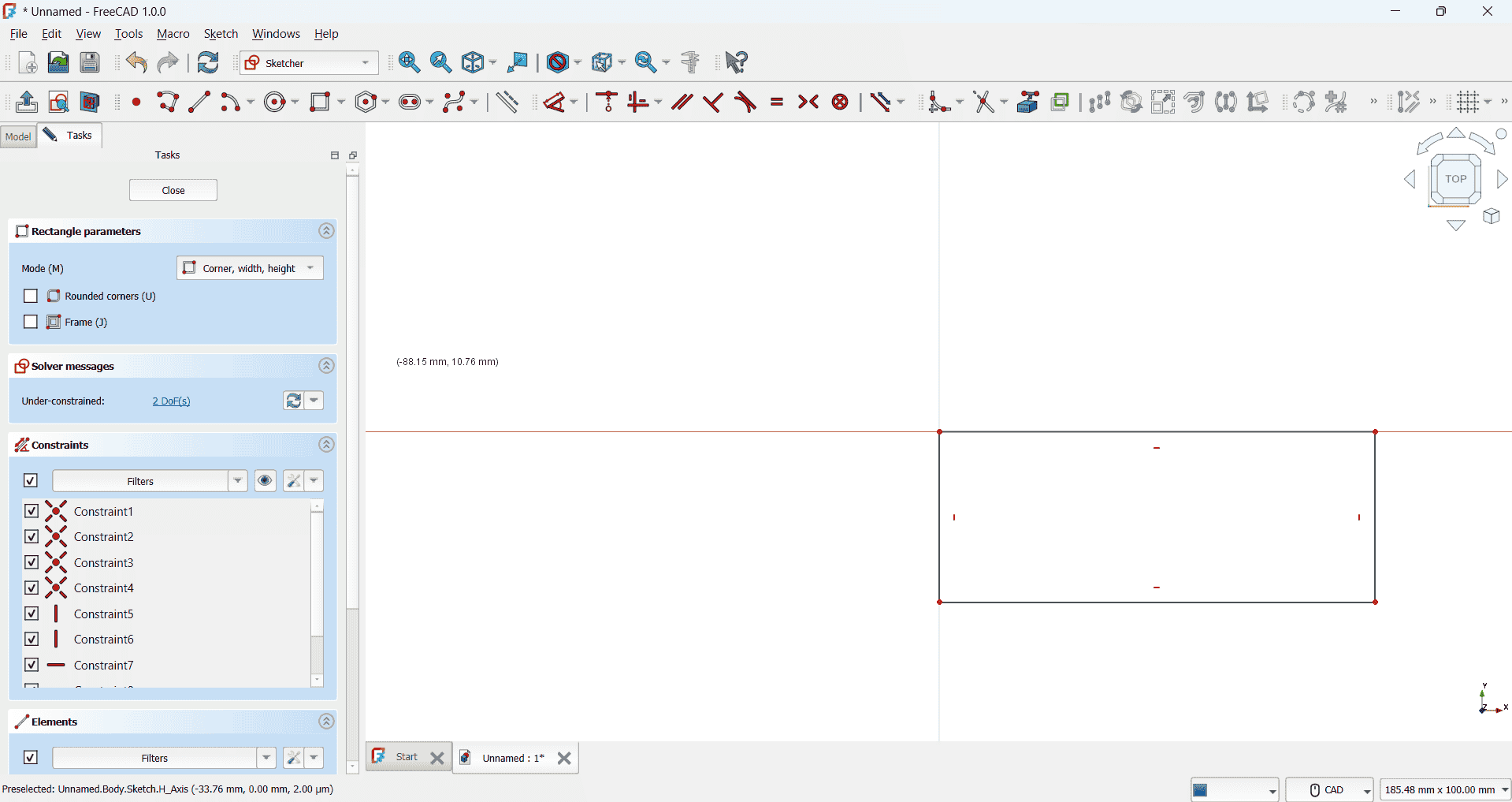
First, I launch the FreeCAD software and navigate to the Sketcher workbench. I then select the XY plane as the base plane for my sketch and confirm my selection by clicking 'OK.' Next, I choose the rectangle tool from the available sketching options and carefully draw a rectangle on the selected plane, ensuring it is positioned accurately as shown in the reference figure. This forms the foundation for my design, which I will further refine by adding dimensions and constraints.
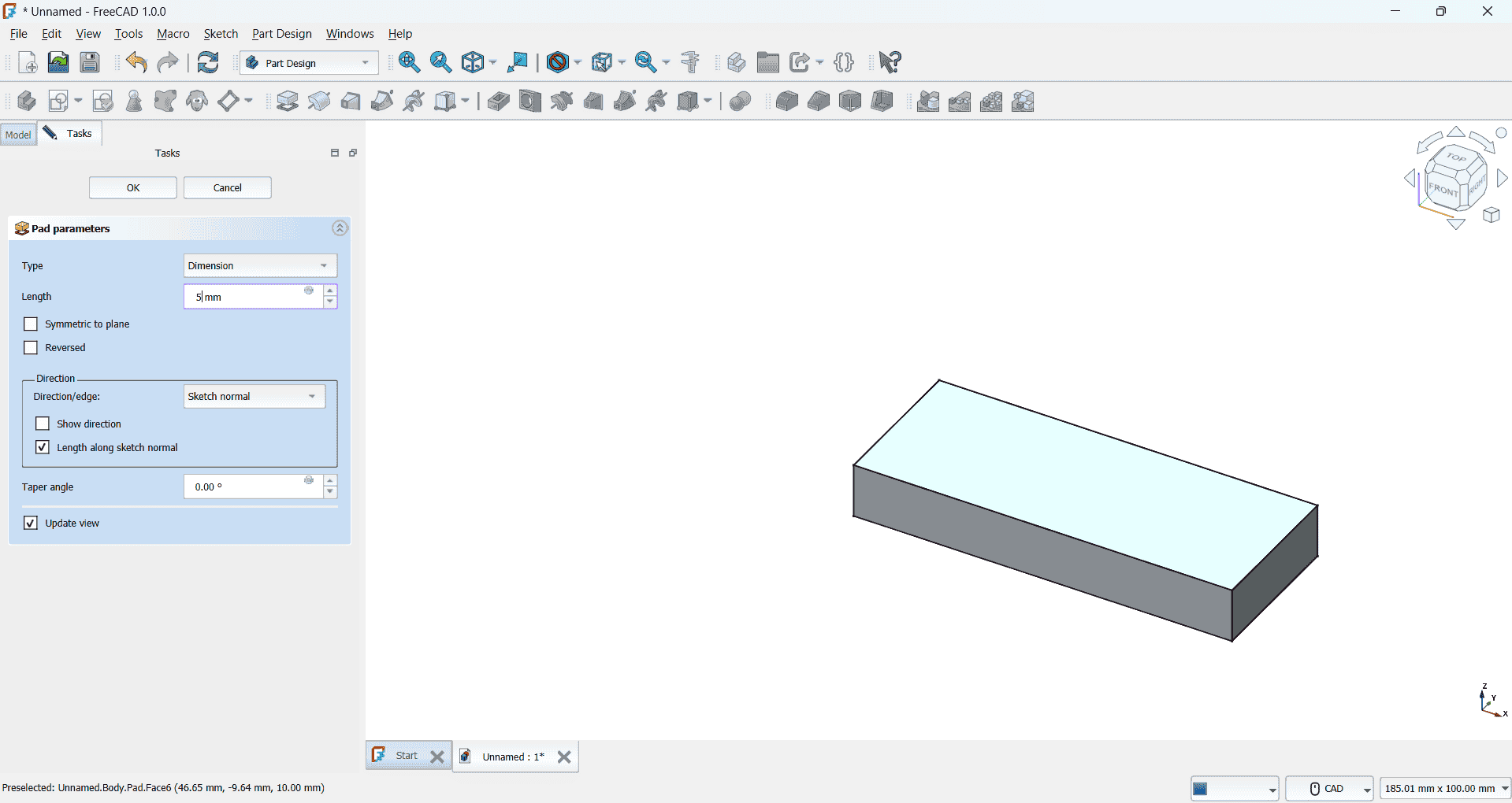
After, completing the rectangle sketch, I proceed to the 'Pad' feature to give it a 3D shape. In the pad parameters, I set the length to 5mm, ensuring the extrusion creates a solid base. Once the pad operation is applied, I create a new sketch on the same XY plane for additional features. Within this sketch, I carefully draw circles at the desired positions, ensuring proper alignment and dimensions. After finalizing the sketch, I use the 'Pocket' tool to perform an extrusion cut, effectively removing material from the solid body to create the required holes or indentations.
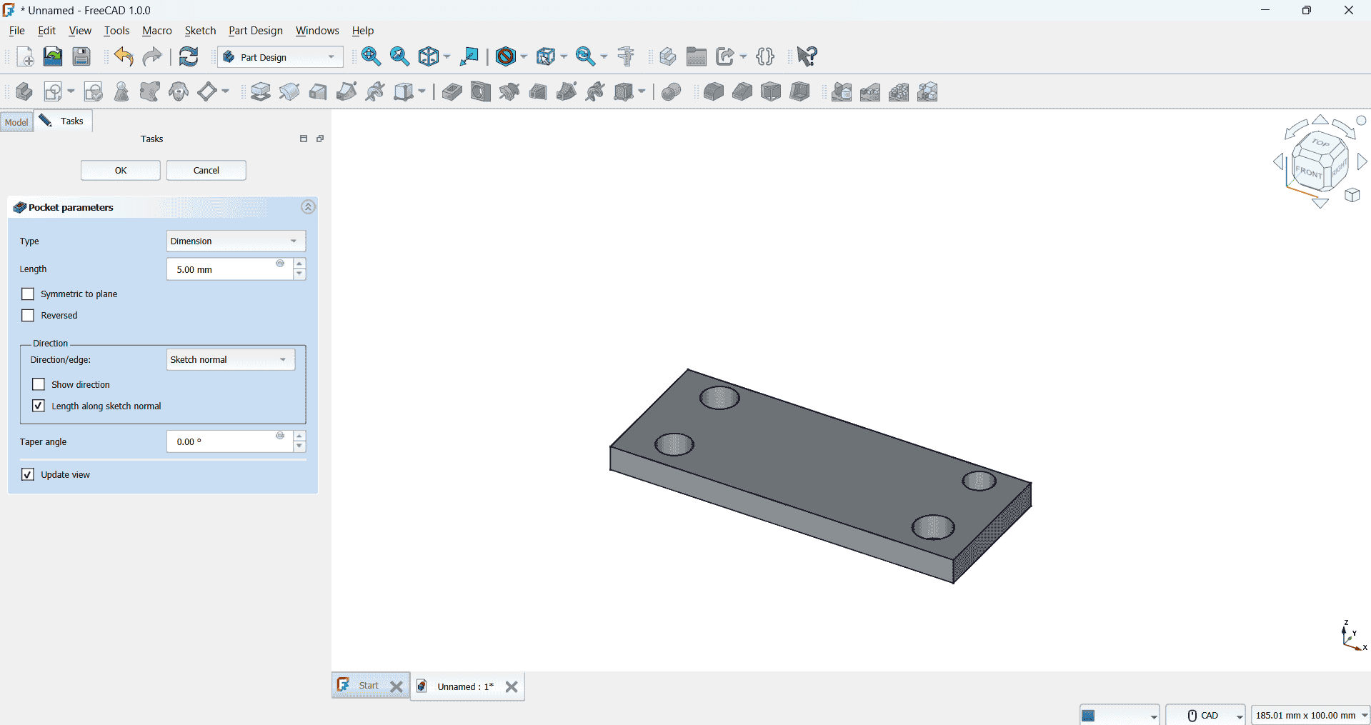
Next, I once again select the XY plane as the base and create a new sketch. In this sketch, I carefully draw a hexagonal shape, ensuring precise alignment and dimensions. After finalizing the sketch, I apply the 'Pocket' tool to cut through the solid body, removing the material as needed. This step helps in shaping the design further. Once the pocket operation is complete, I refine the model by applying the 'Fillet' tool to smooth out sharp edges, enhancing both the aesthetics and functionality of the final design.
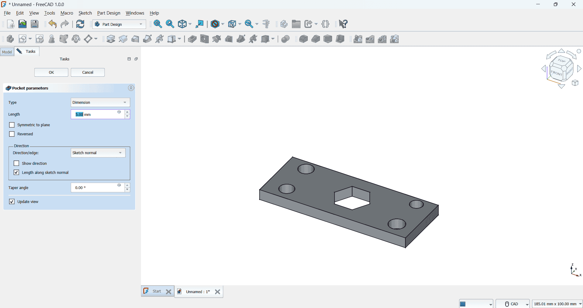
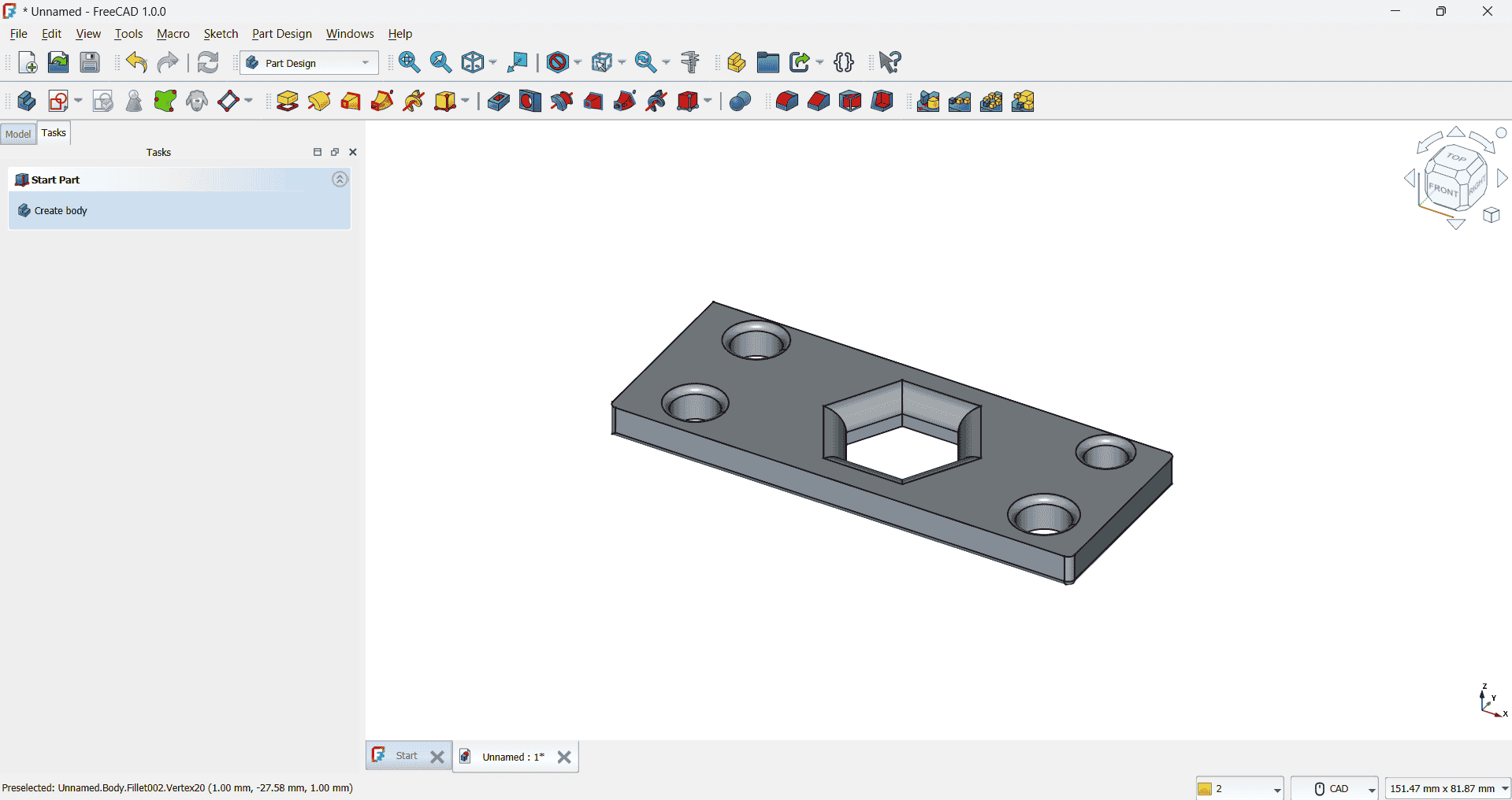
This is my first time using FreeCAD software for this assignment, and it has been a valuable learning experience. Through this process, I have gained an understanding of how to create sketches, work with various tools, and navigate the software efficiently. I learned how to build and apply the 'Pad' parameters to give a 2D sketch a 3D form, as well as how to use the 'Pocket' tool to create cutouts and remove material. This experience has introduced me to essential CAD modeling techniques, enhancing my skills and deepening my understanding of 3D design.
Solidworks: 3D Design Software
SolidWorks is an industry-leading 3D CAD (Computer-Aided Design) software used for creating highly detailed 3D models, parts, assemblies, and 2D drawings. It is renowned for its ease of use, parametric design capabilities, and wide range of features that make it a go-to tool for engineers, designers, and manufacturers. With SolidWorks, users can design mechanical components, perform simulations for stress, thermal, and motion analysis, and create highly accurate representations of their designs.
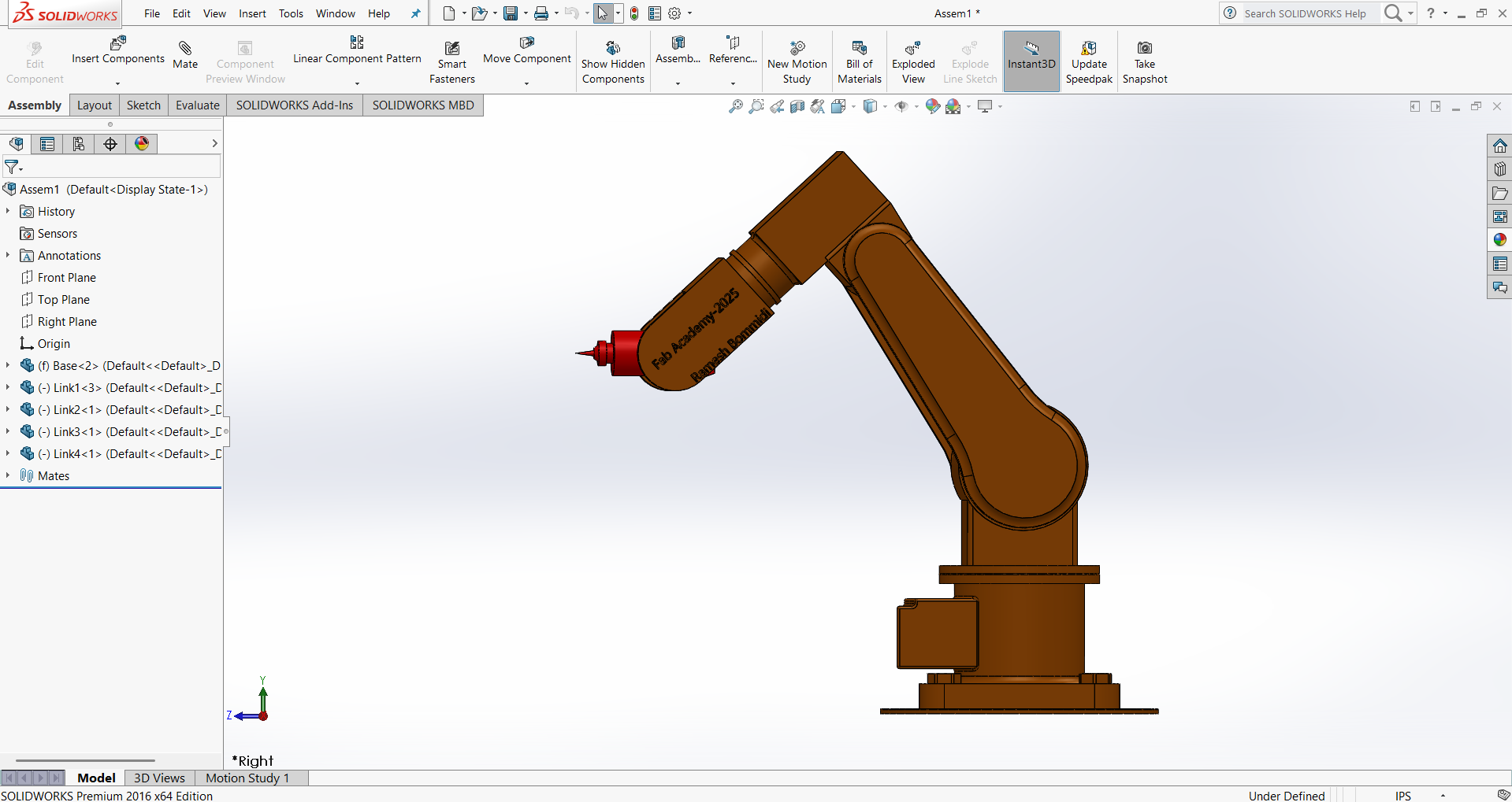
The 2016 version of SolidWorks introduced various updates and improvements to enhance the user experience. Notable enhancements included better performance for large assemblies, improved sketching tools, and new features for part design, sheet metal, and 3D rendering. Additionally, the software provides integration with other tools such as CAM (Computer-Aided Manufacturing) for machining and CNC (Computer Numerical Control) operations, making it an all-encompassing tool for the entire product design process.
SolidWorks also includes capabilities for creating complex geometries, simulating real-world conditions, and generating technical drawings for manufacturing. The software supports a vast array of file formats, allowing for seamless collaboration across different design and engineering teams.
However, it’s essential to note that using cracked or pirated versions of software like SolidWorks is illegal and comes with significant risks. Cracked versions often lack essential updates, security patches, and support, and can expose your work to potential data corruption or loss. Using a legitimate, licensed version not only ensures you get the full range of features and updates but also supports the software developers who work hard to improve and maintain the program.
For this assignment, I have decided to design a DOF (Degrees of Freedom) robotic arm. The DOF in robotics refers to the number of independent movements or axes the arm can make, allowing it to perform a range of tasks with precision and flexibility. I aim to create a design that includes multiple joints and actuators, which can be controlled to move the arm in a three-dimensional space.
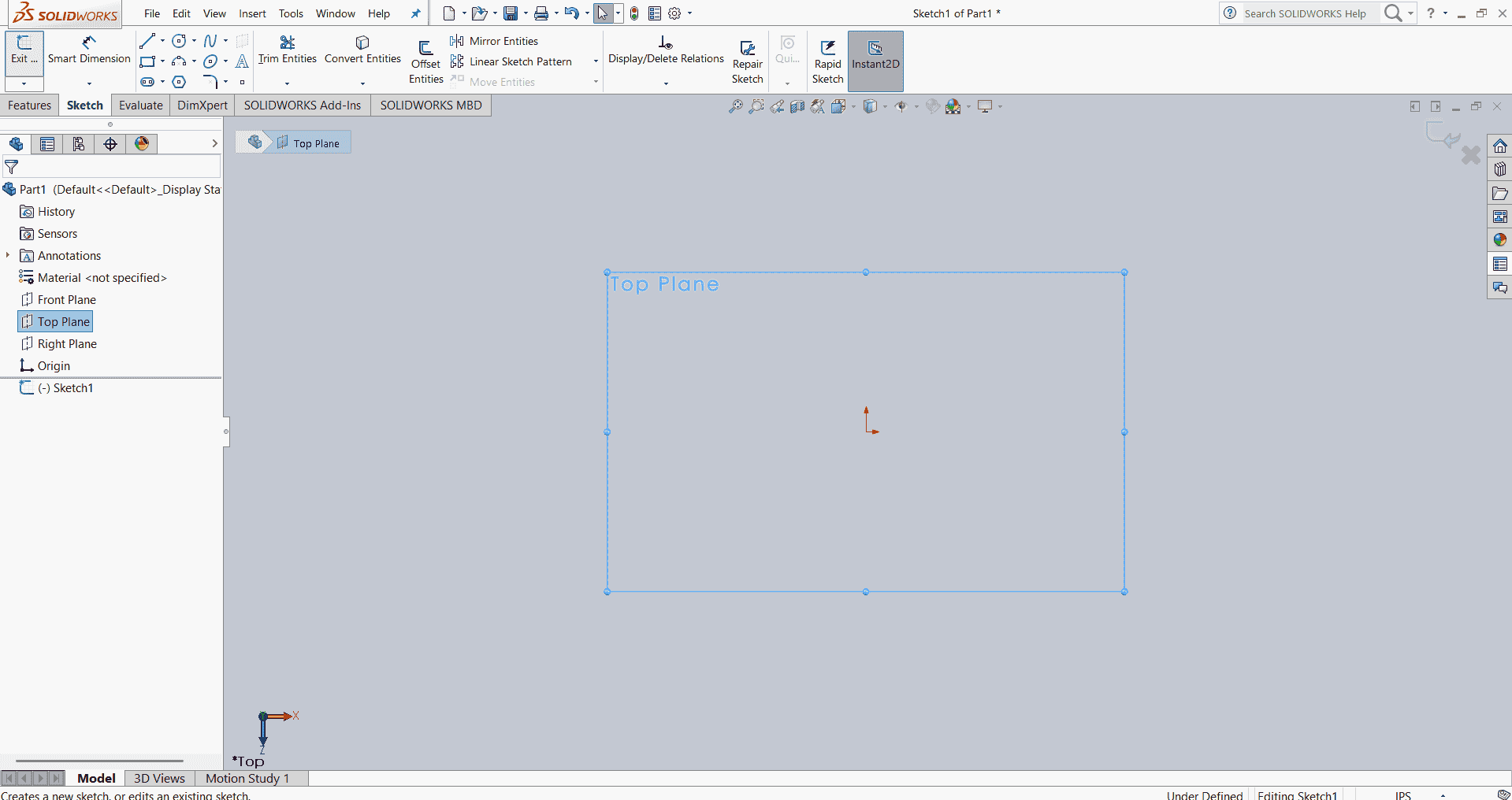
First begin creating a sketch, I first open the 'Sketch' option from the toolbar at the top, as shown in the image. Once the 'Sketch' option is selected, I choose one of the three available planes—XY, XZ, or YZ—on which to draw. After selecting the top plane (XY plane) for my sketch, I can utilize the drawing toolbar to access various drawing tools such as line, rectangle, circle, and curves, among others, to create the desired shapes for my design.
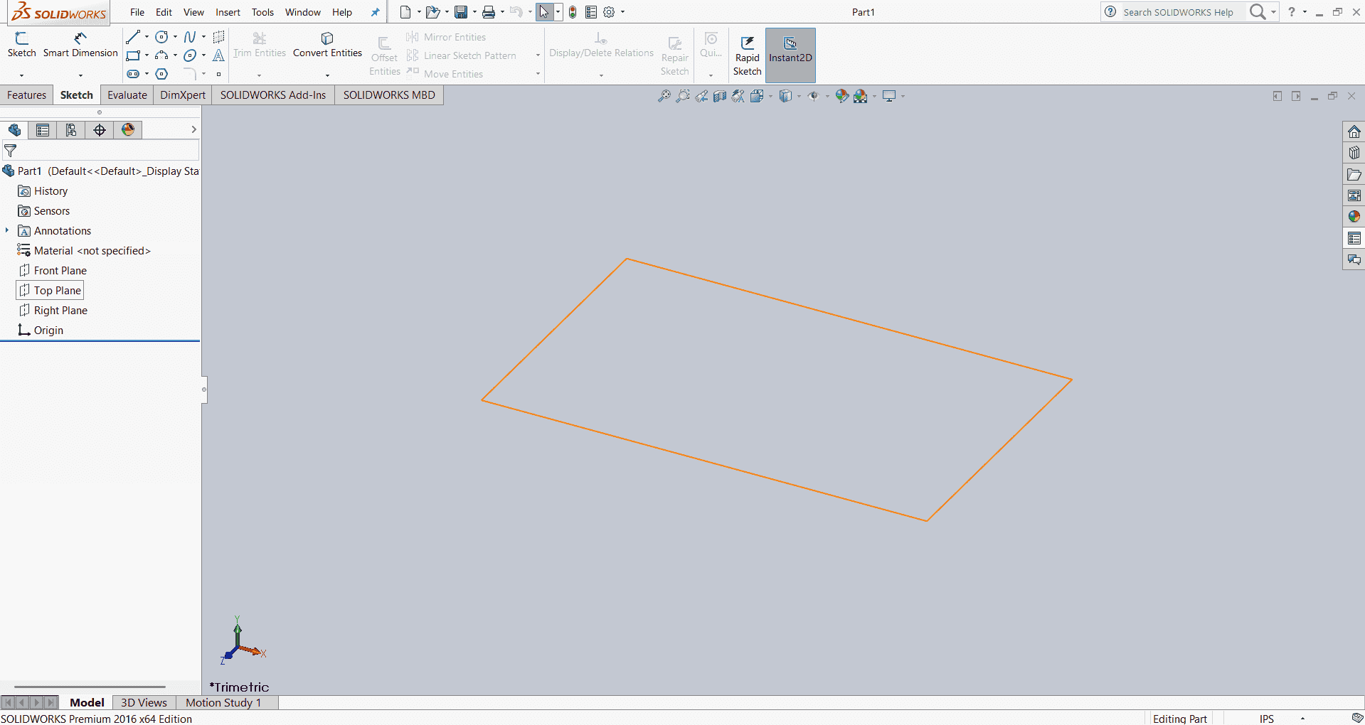
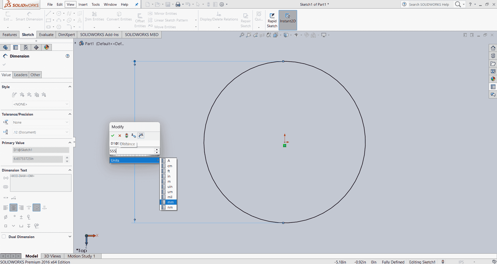
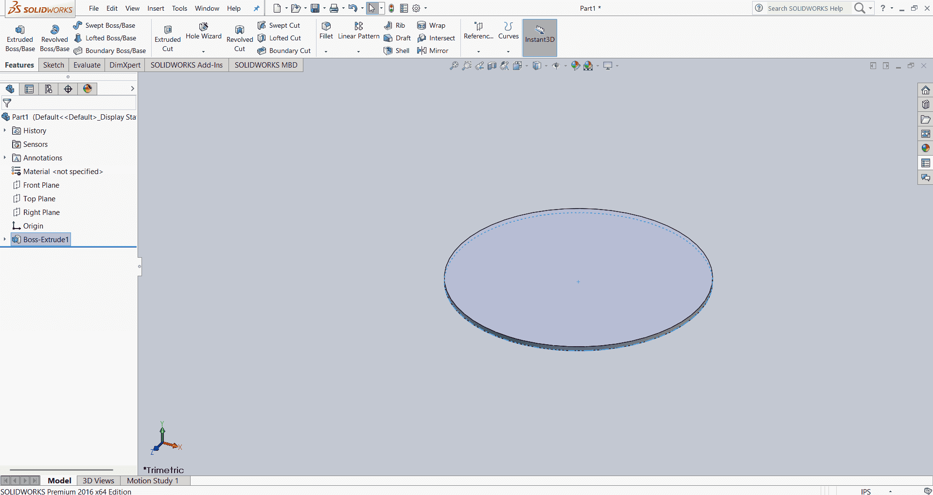
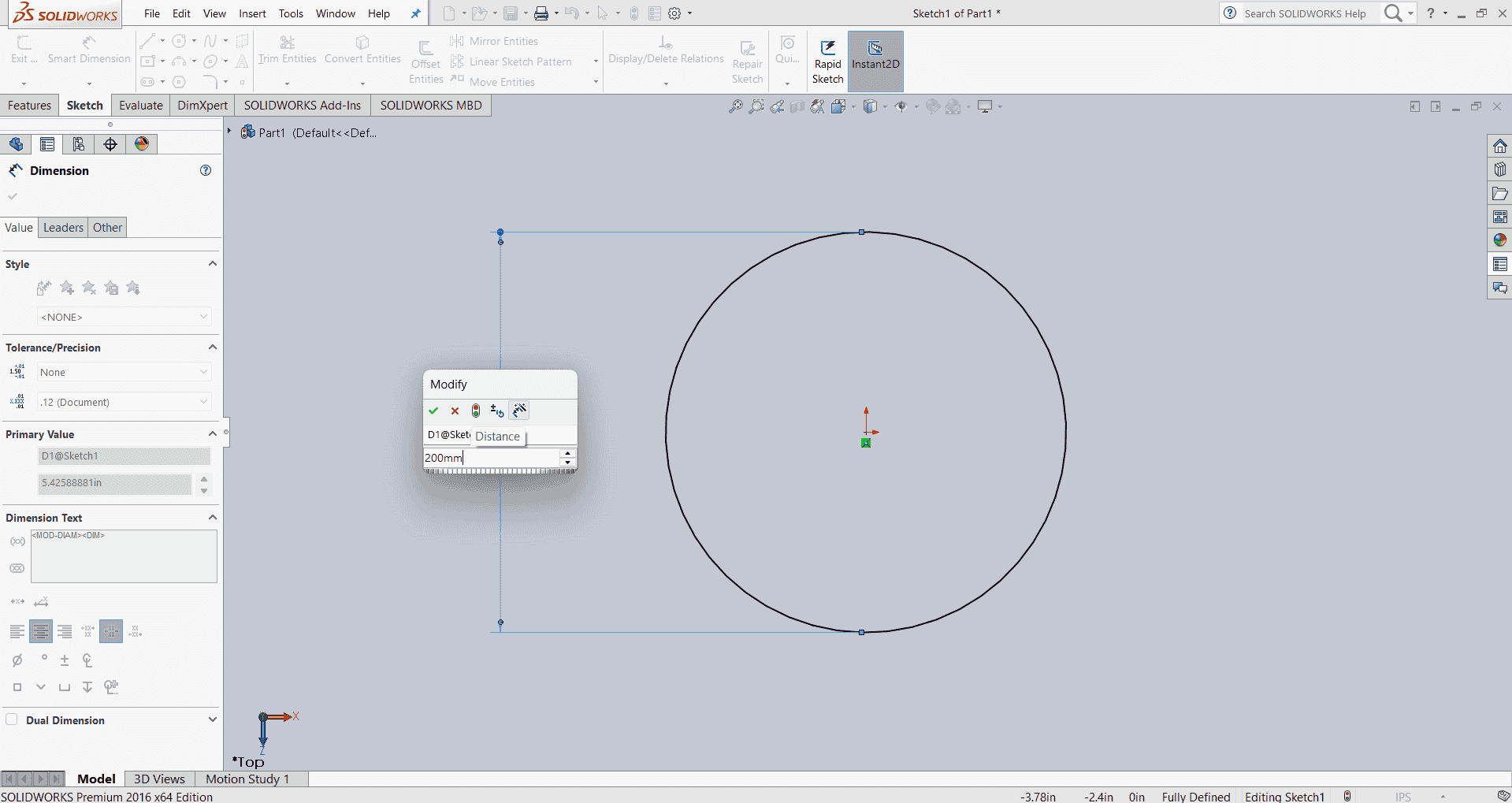
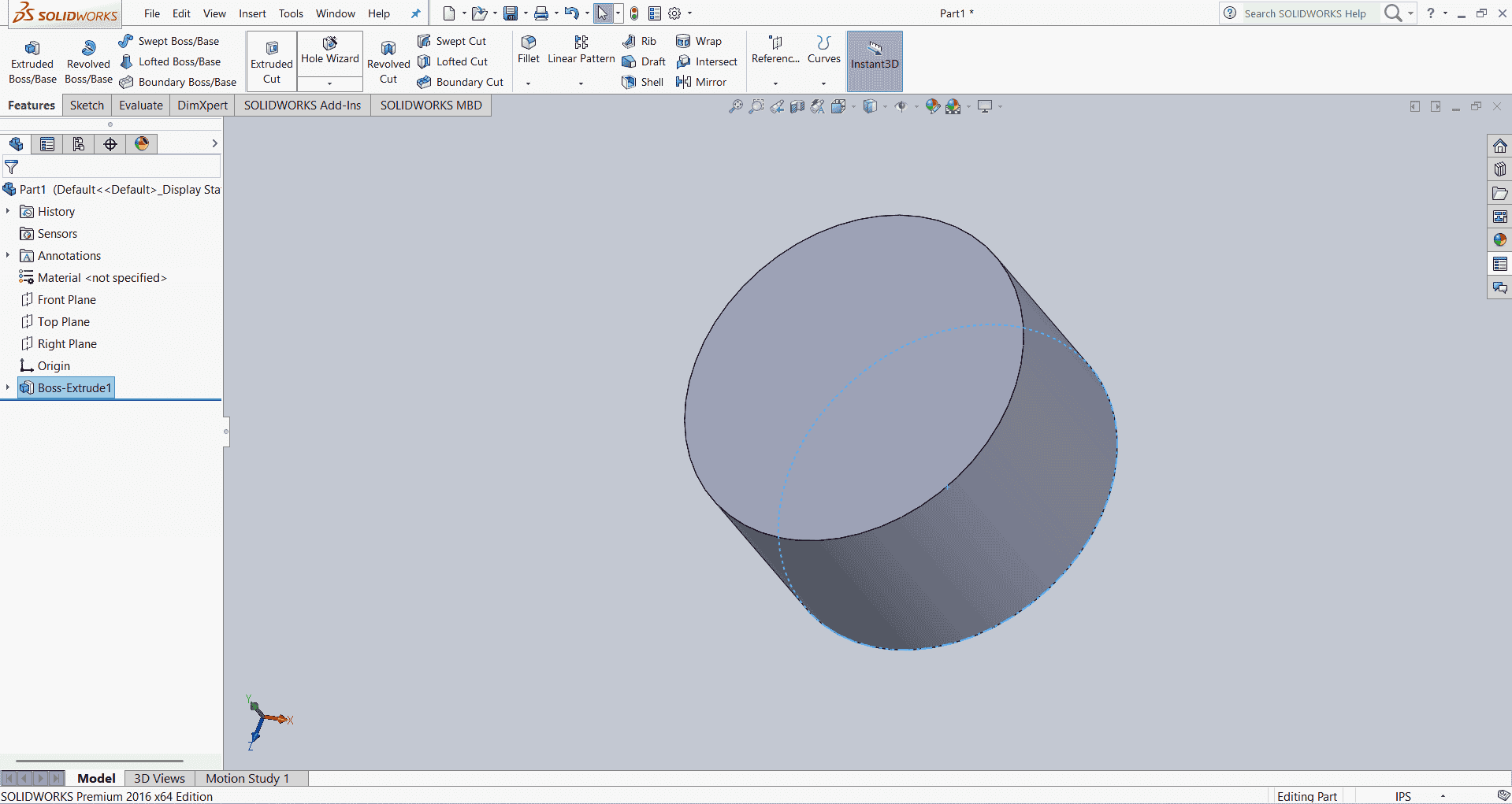
After, deciding to design the base for the DOF robot, I created a circle and extruded it. Then, I sketched a rectangle on top of the circle and extruded that as well.
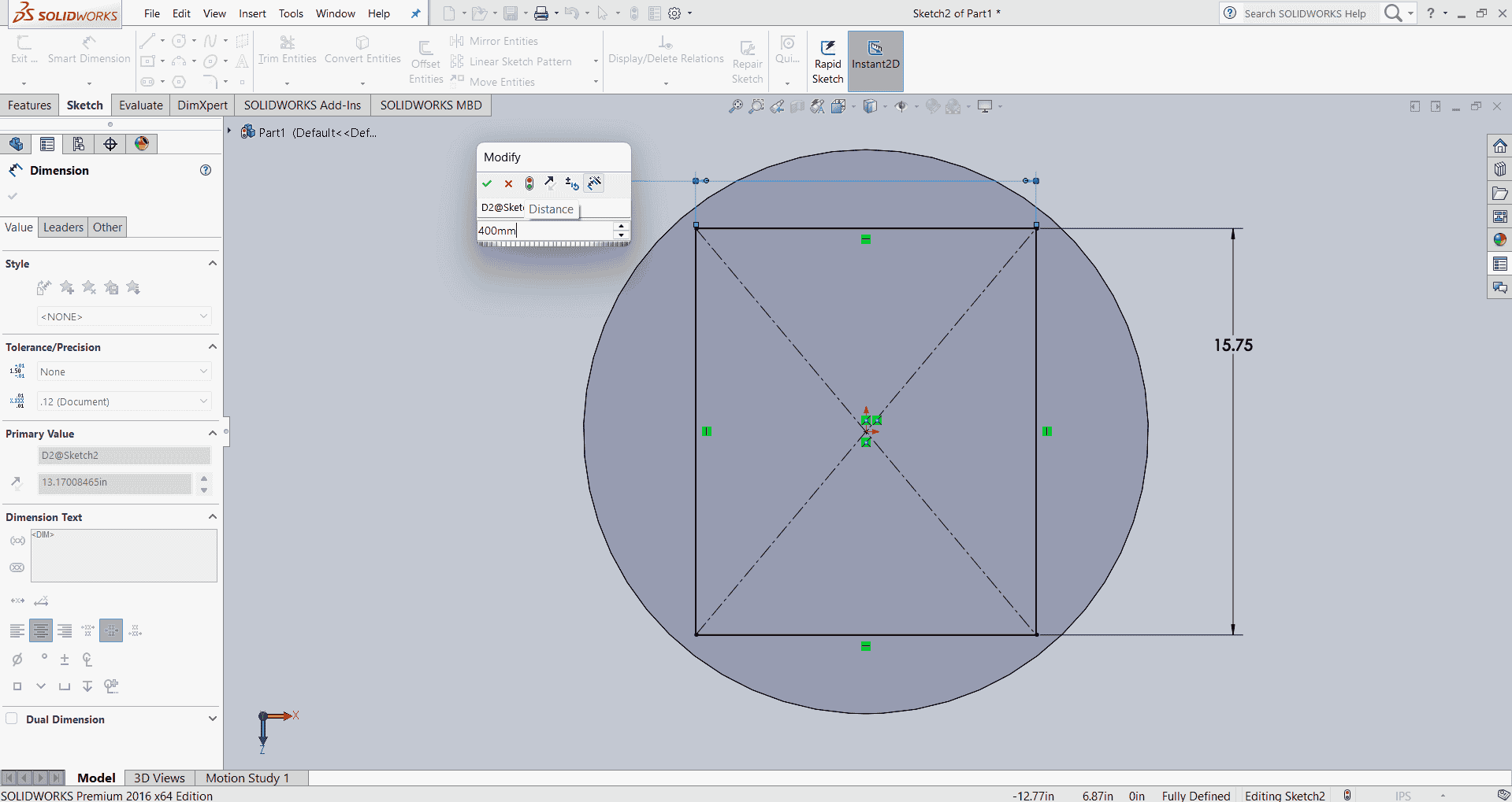
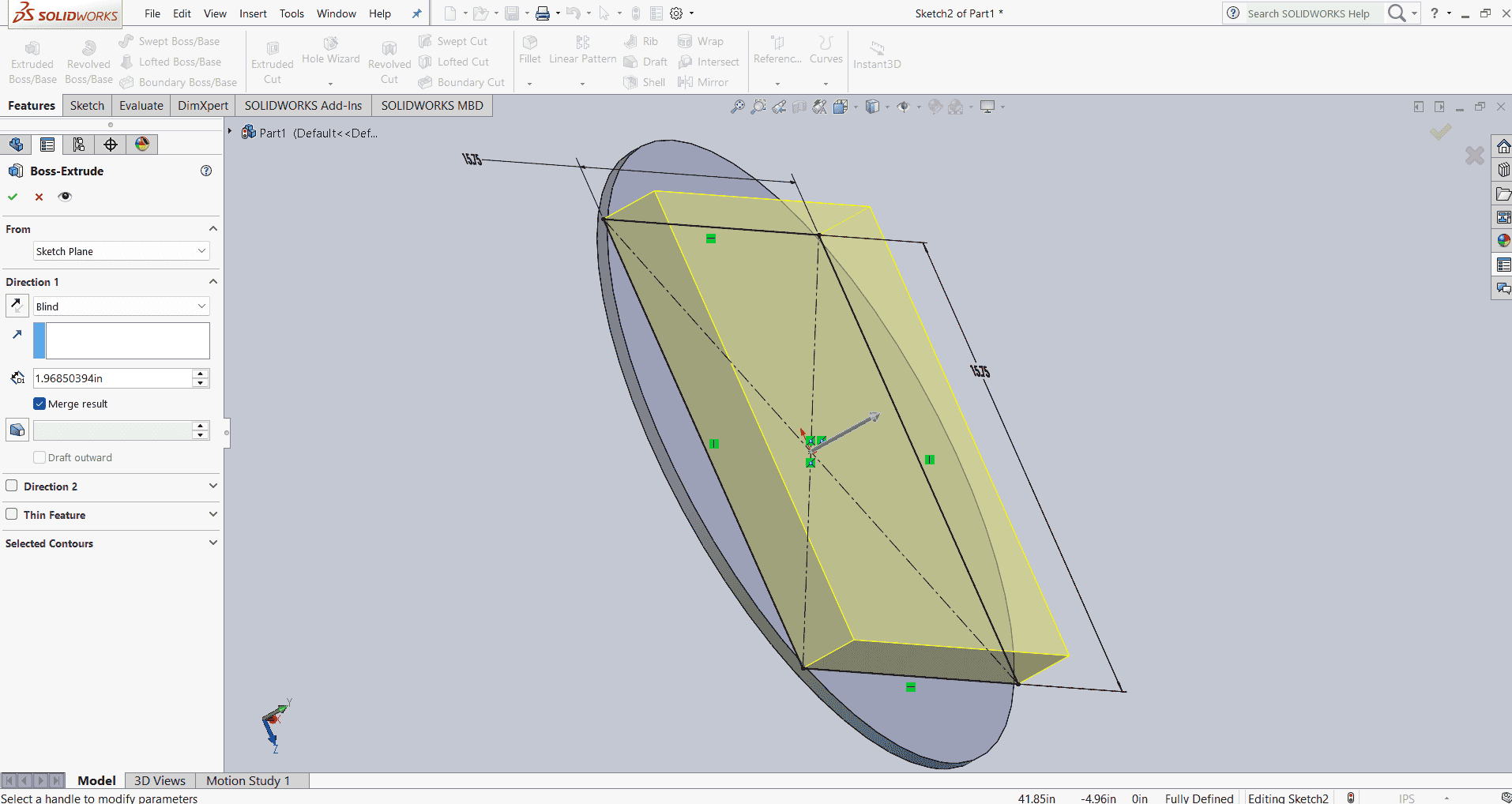
After applying a fillet to my model, I created a new sketch, drew a circle, and extruded it.
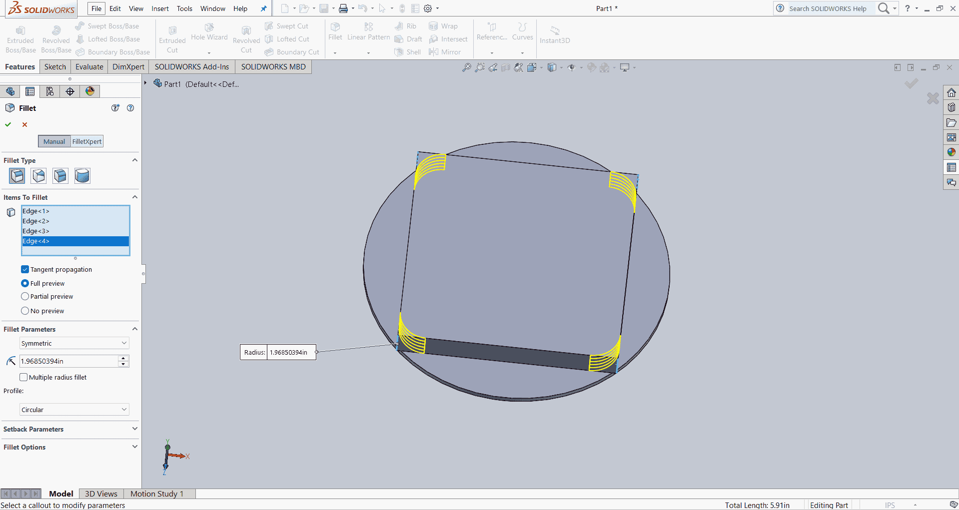
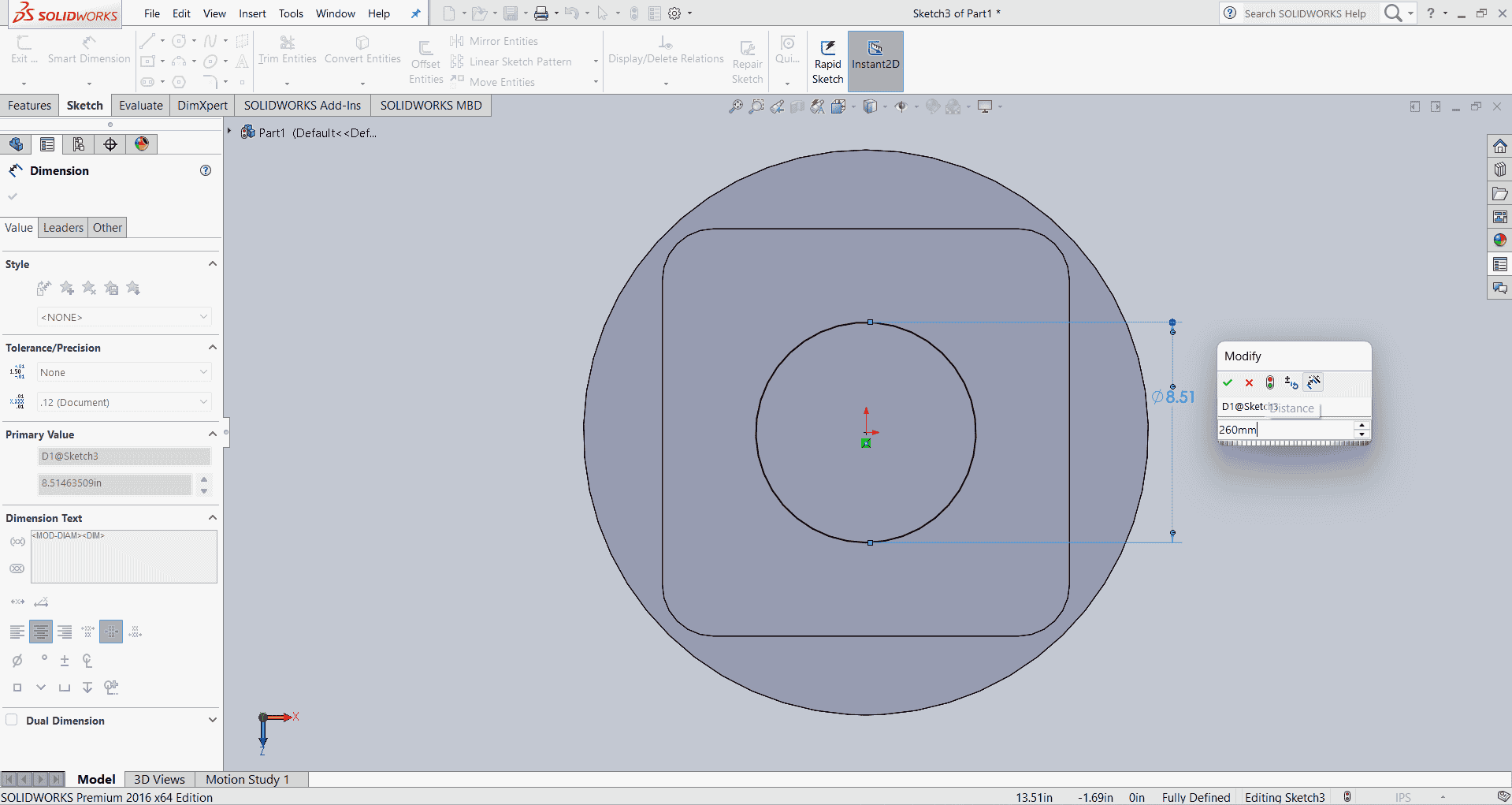
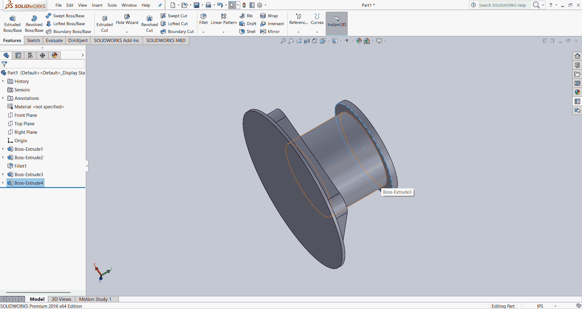
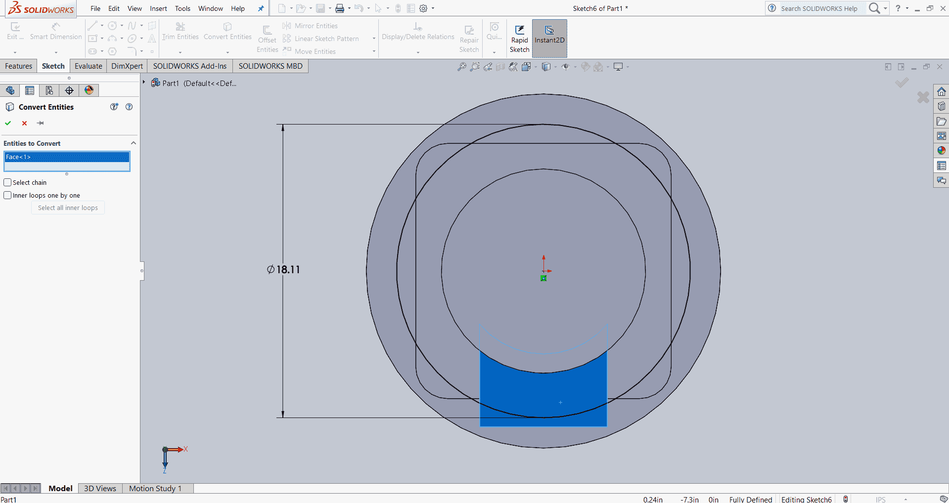
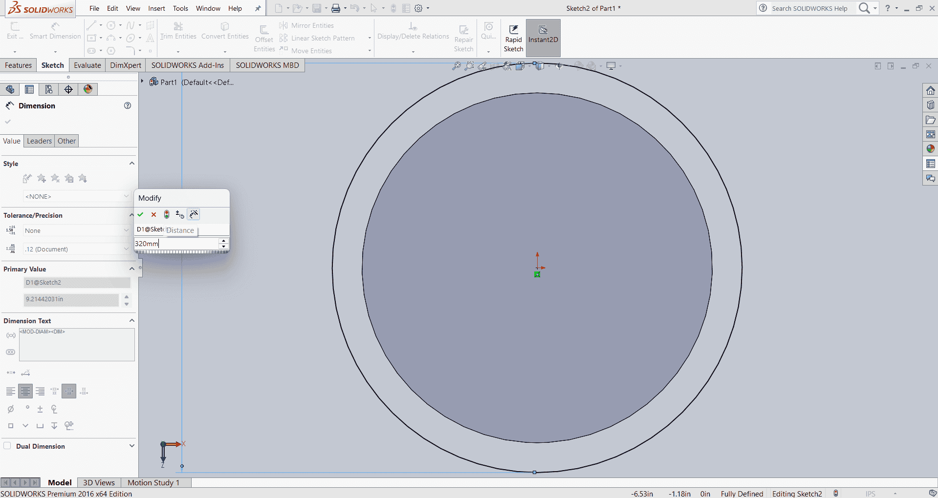
After finalizing the design of the robotic arm's base, I applied fillets to smooth the edges, enhancing both aesthetics and structural integrity. Subsequently, I created a new sketch on the top face of the base, drew a circle, and extruded it to form a cylindrical feature. This addition serves as a mounting point for the arm's components, ensuring stability and proper alignment.
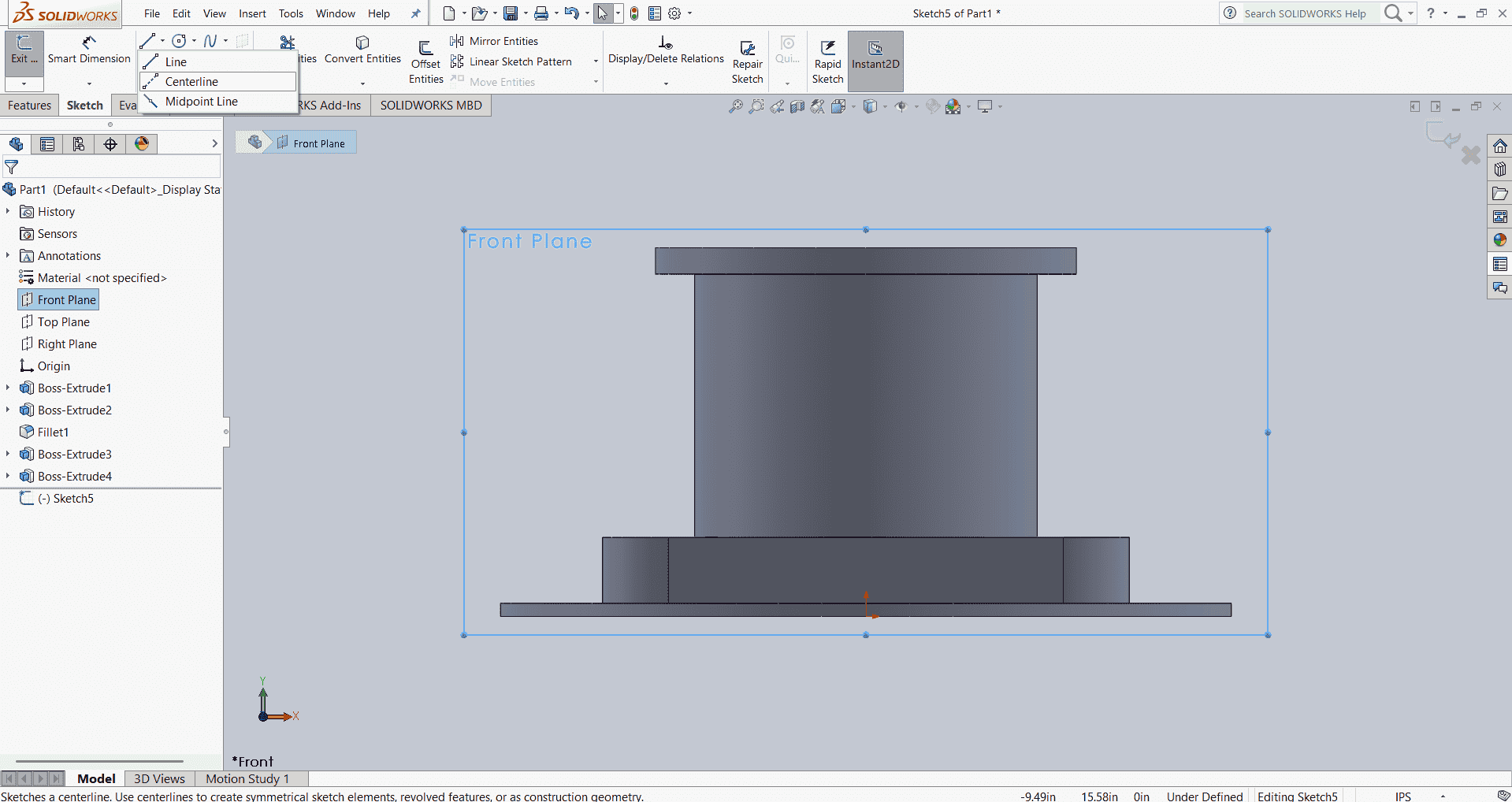
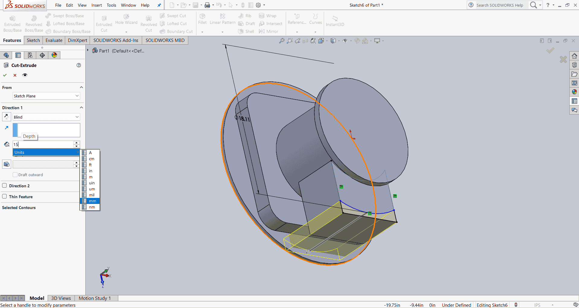
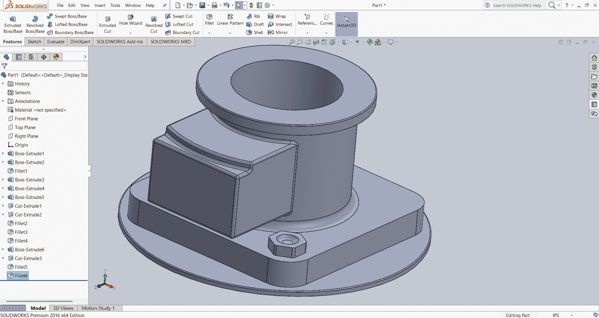
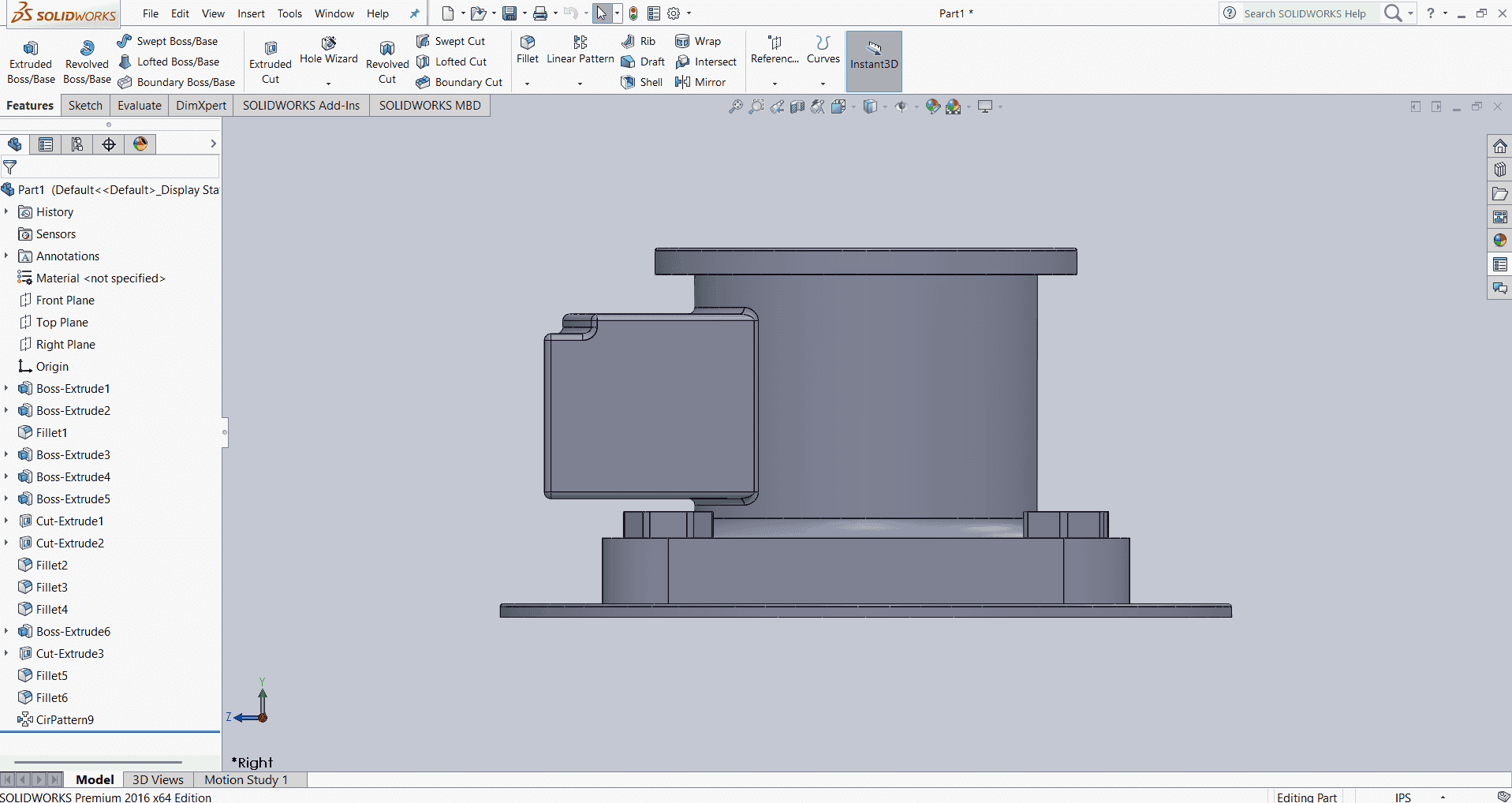
After finalizing the base design of the robotic arm, I proceeded to design Link 1. I began by creating a new sketch, drawing a circle, and extruding it to form the initial cylindrical shape. Subsequently, I developed additional sketches to match the specific requirements depicted in the reference figure. To achieve the desired geometry, I utilized the "Extruded Cut" feature to remove material where necessary and applied fillets to smooth certain edges, enhancing both the functionality and aesthetics of Link 1.
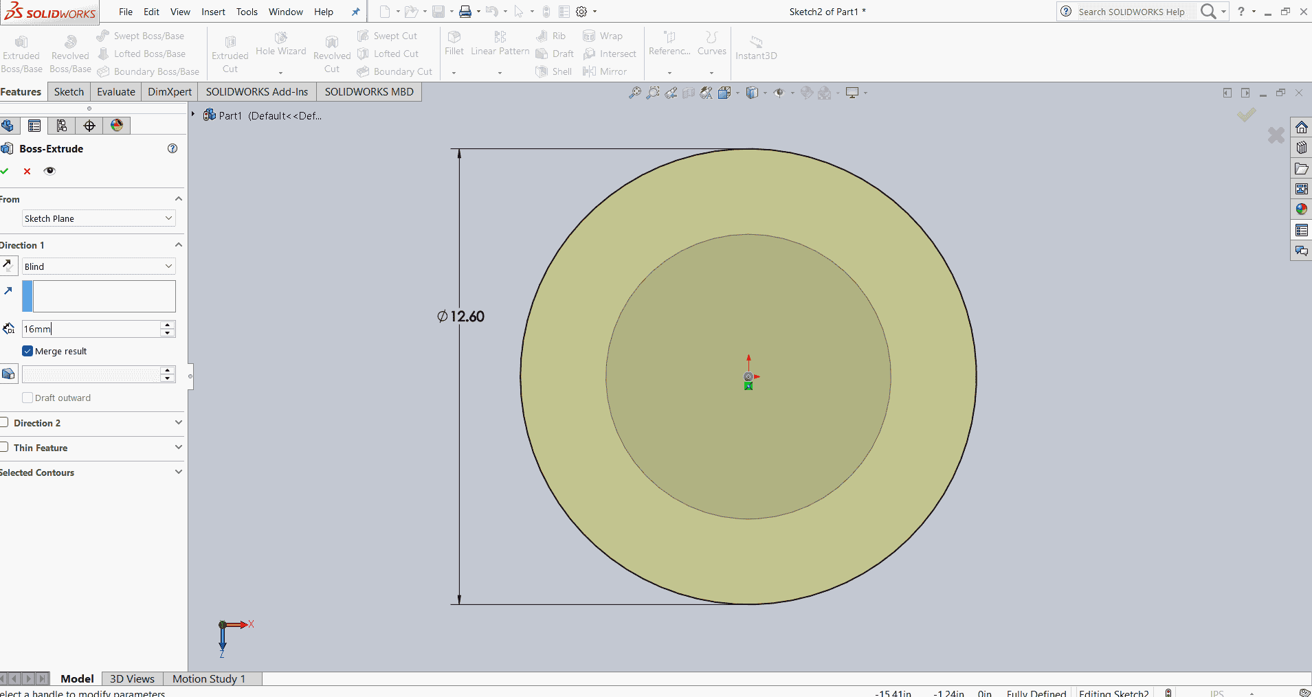
After finalizing the design of Link 1, I proceeded to create a new sketch to incorporate the fillet design as depicted in the reference figure. To achieve this, I utilized the "Sketch Fillet" tool in SOLIDWORKS.
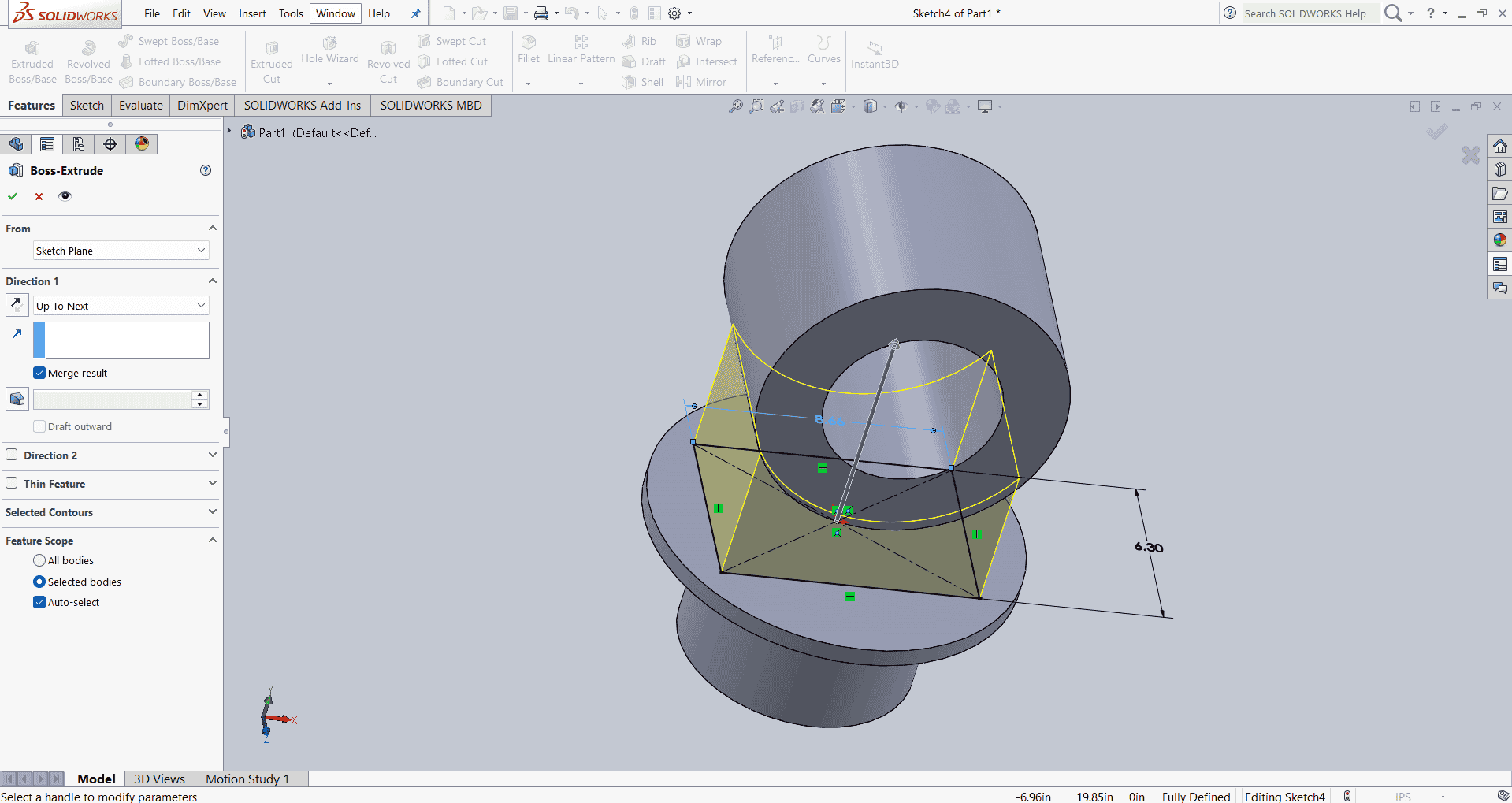
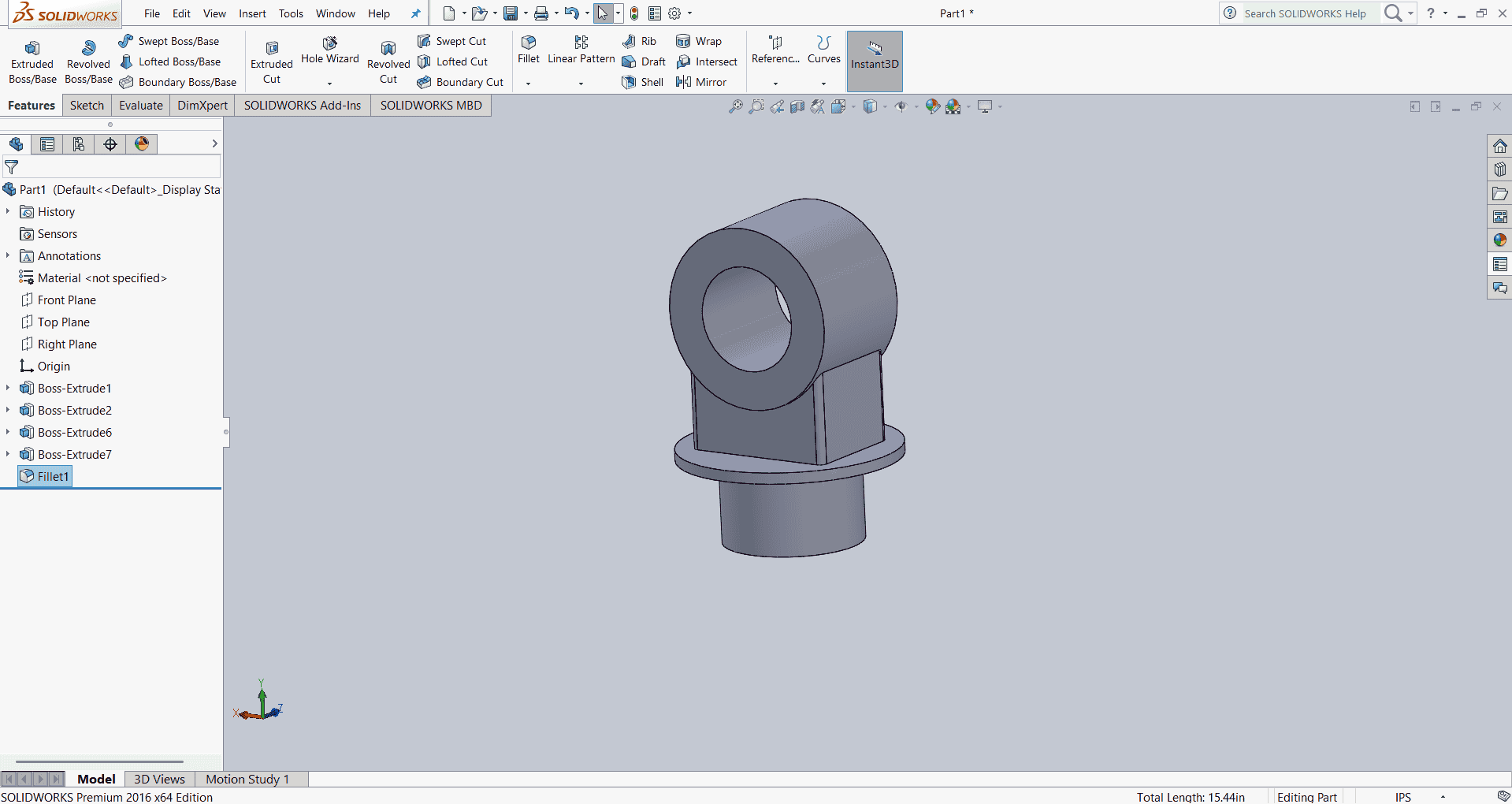
After completing the design of Link 2, I proceeded to design Link 2. I began by creating a new sketch, drawing two circles, and connecting them using the line tool. Next, I trimmed the necessary lines using the trim option. I then proceeded to extrude the sketch and applied the mirror tool to complete the design of Link 2 as shown in the figure.
To ensure the design met the required specifications, I referred to the reference figure, which provided detailed dimensions and features for Link 2. This guided me in accurately positioning and sizing the circles and lines within the sketch.
After trimming the unnecessary lines, I used the "Extrude Boss/Base" feature to give Link 2 its three-dimensional form. This step added depth to the sketch, transforming it into a solid body.
To enhance the design and ensure symmetry, I applied the "Mirror" feature. This tool allowed me to duplicate the geometry across a selected plane, ensuring that both sides of Link 2 were identical.
Throughout the design process, I utilized SOLIDWORKS' parametric modeling capabilities, which enabled me to make adjustments to dimensions and features efficiently. This flexibility is crucial in mechanical design, as it allows for quick modifications and optimizations.
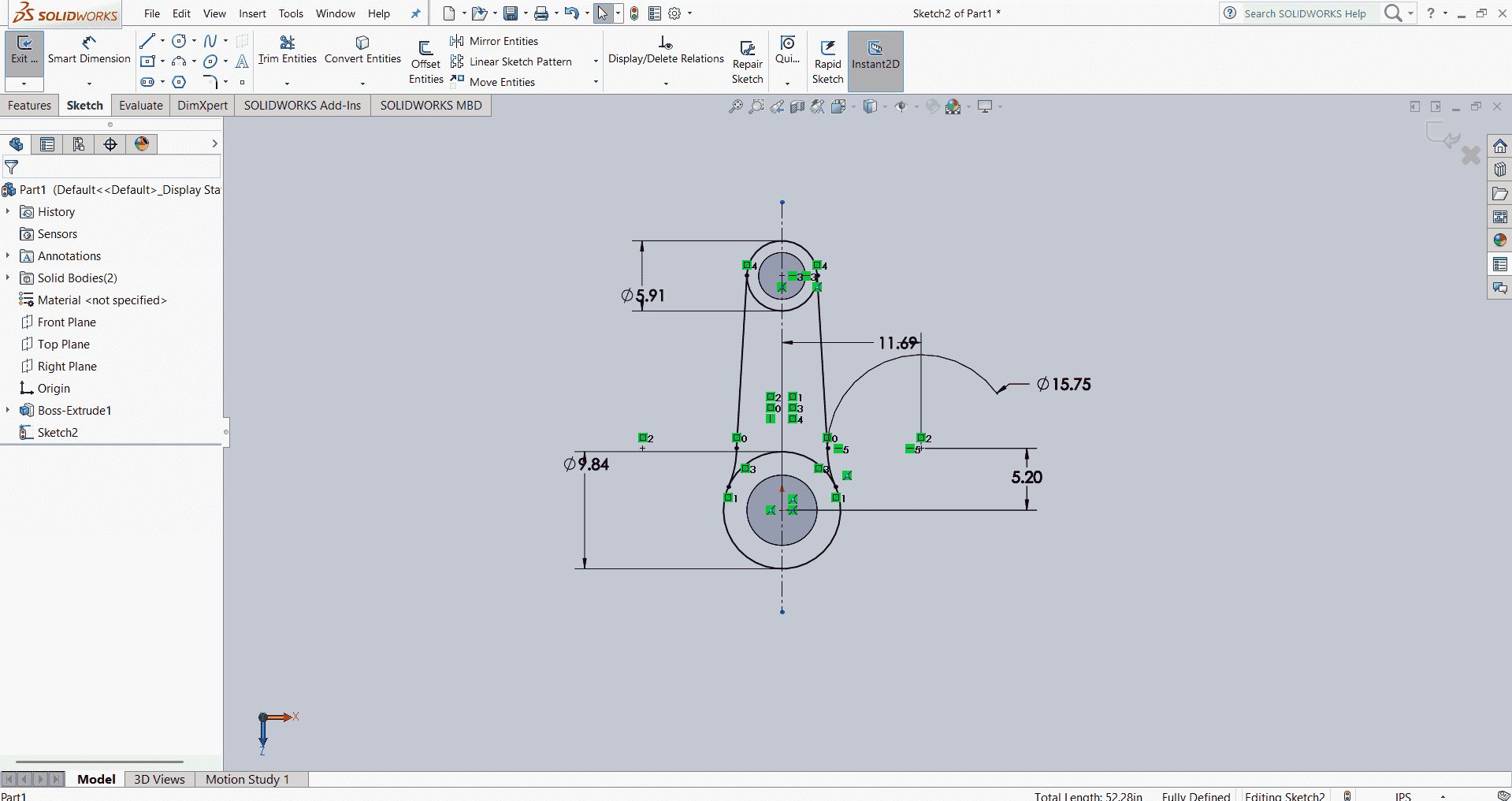
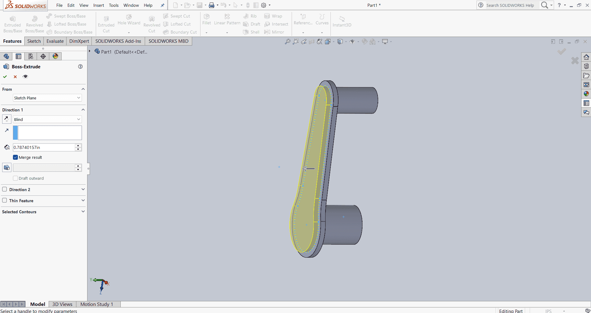
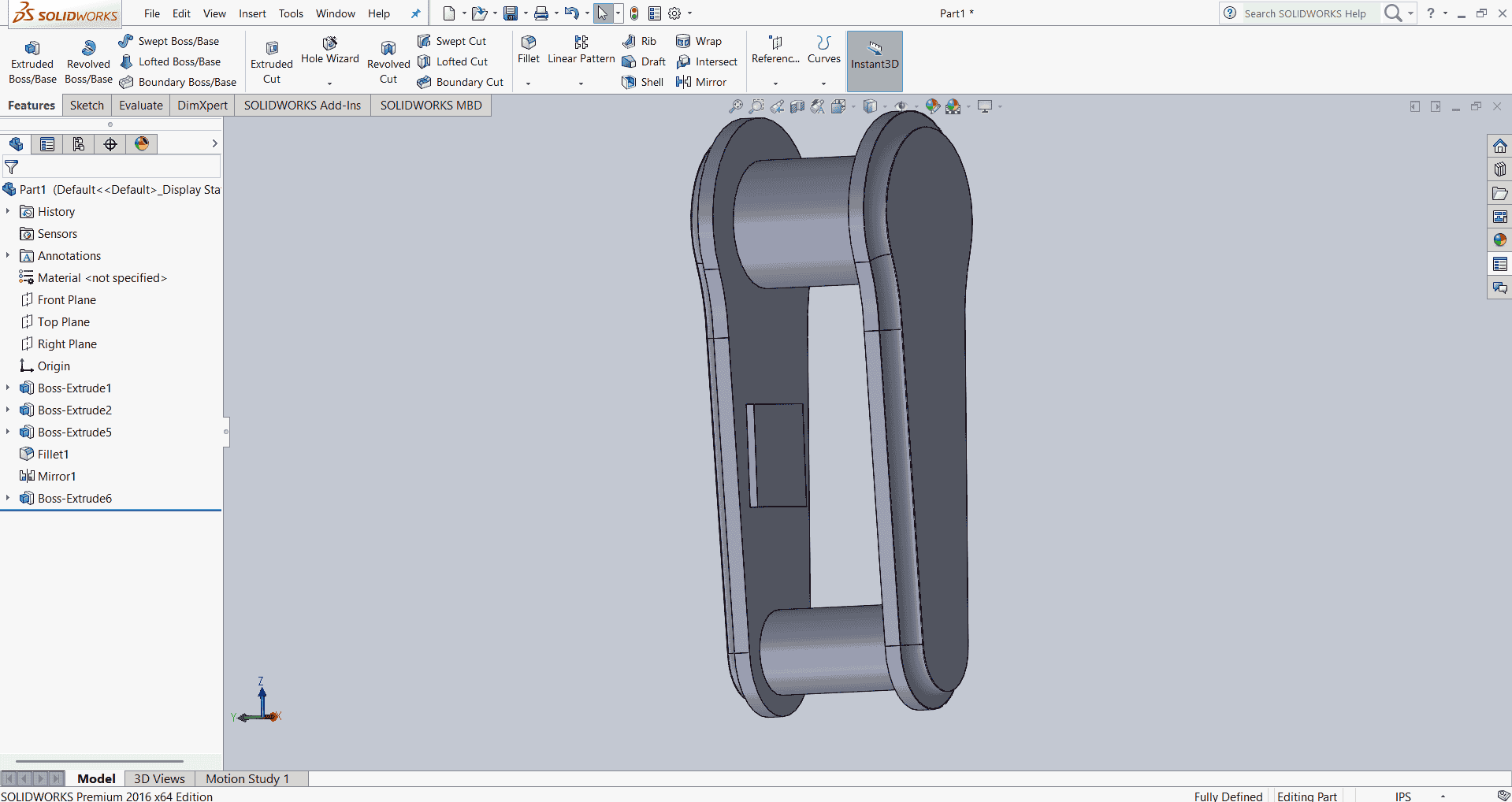
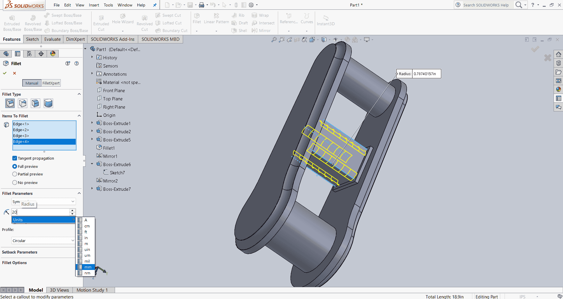
After completing the design of Link 2, I proceeded to design Link 3. I began by creating a new sketch on the desired plane, drawing two circles to represent the cross-sectional profiles of Link 3. Using the "Line" tool, I connected the circles to form the basic outline of the link.
Next, I utilized the "Trim Entities" tool to remove any unnecessary lines, ensuring the sketch was clean and accurate. This step is crucial for eliminating unwanted parts and achieving the desired shape
With the finalized sketch, I applied the "Extrude Boss/Base" feature to give Link 3 its three-dimensional form. This step added depth to the sketch, transforming it into a solid body.
To enhance the design and ensure symmetry, I applied the "Mirror" feature. This tool allowed me to duplicate the geometry across a selected plane, ensuring that both sides of Link 3 were identical.
Throughout the design process, I utilized SOLIDWORKS' parametric modeling capabilities, which enabled me to make adjustments to dimensions and features efficiently. This flexibility is crucial in mechanical design, as it allows for quick modifications and optimizations.
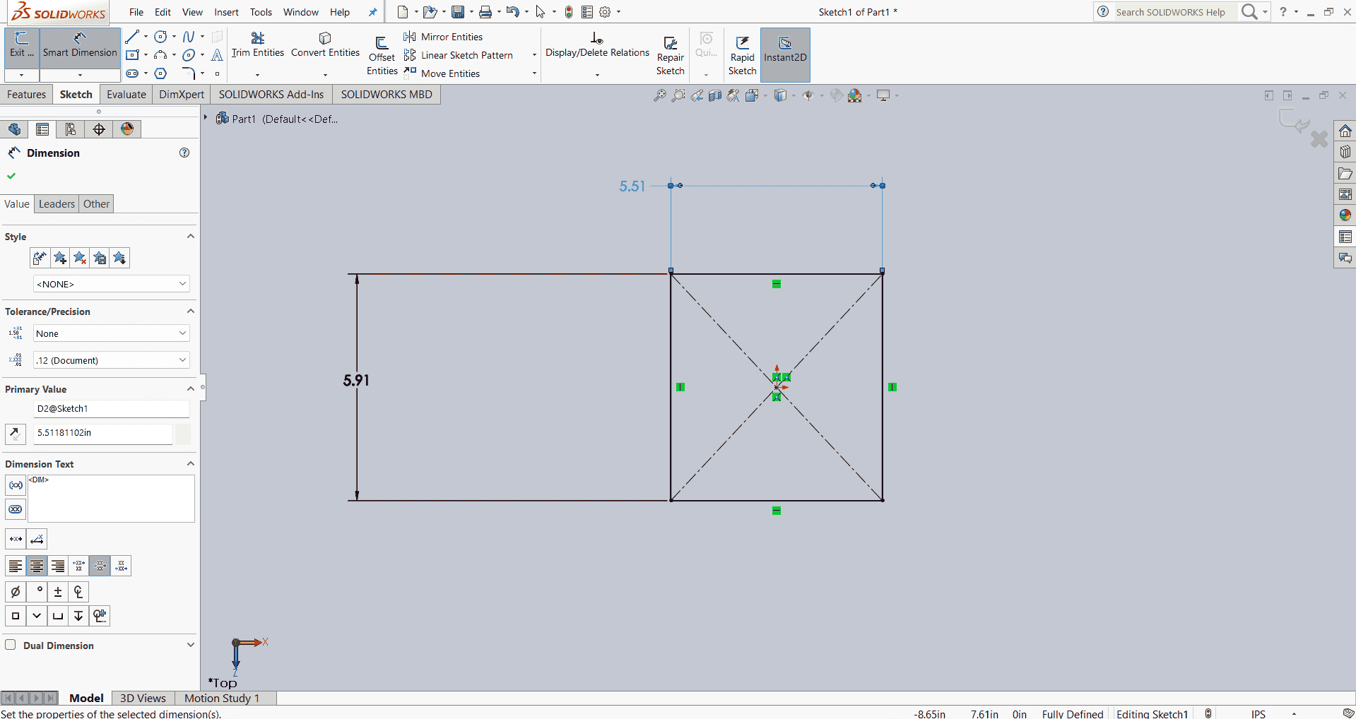
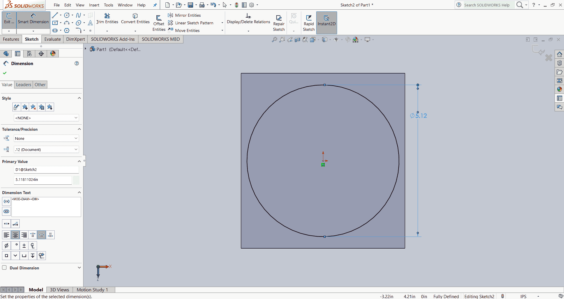
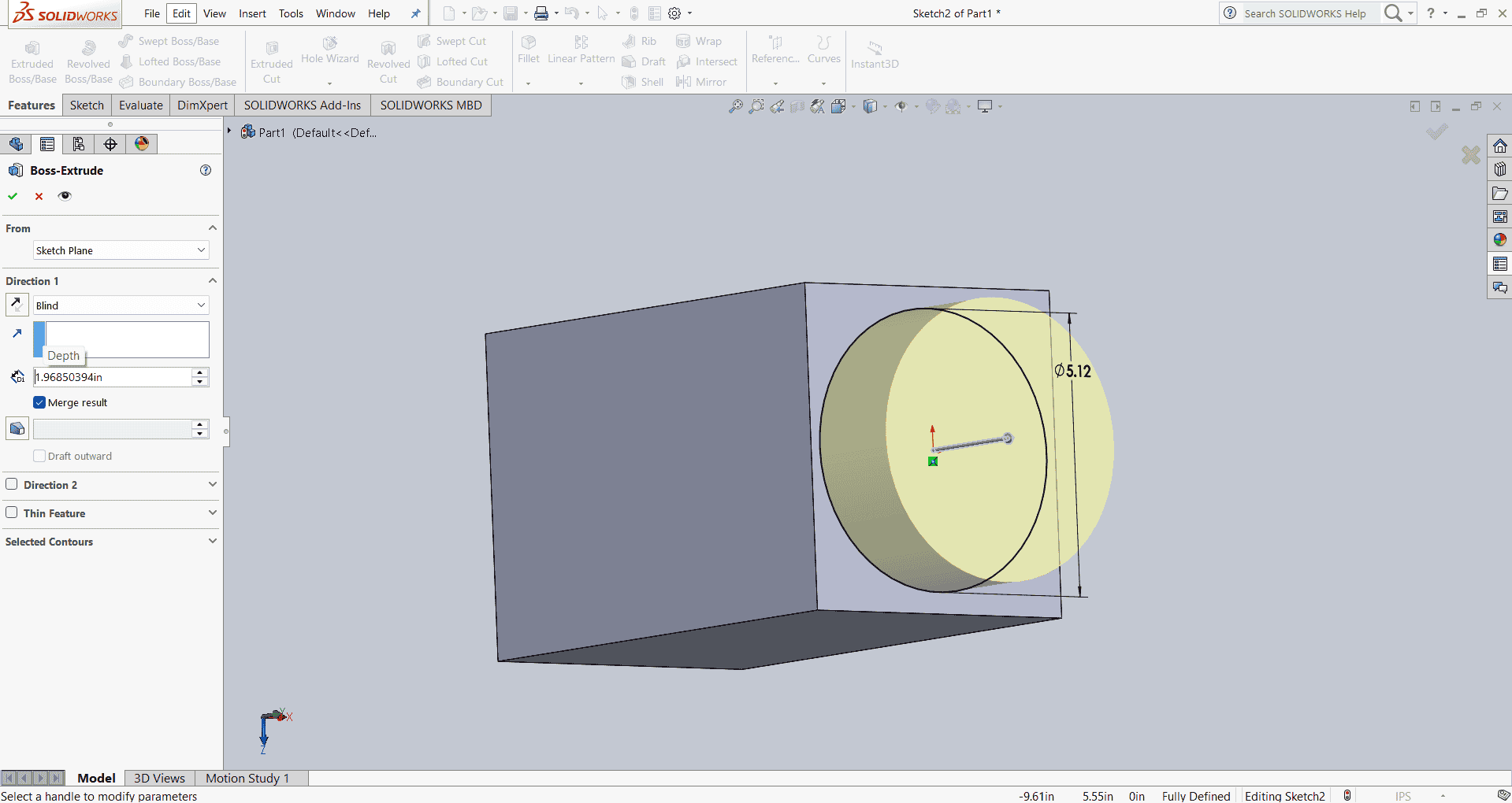
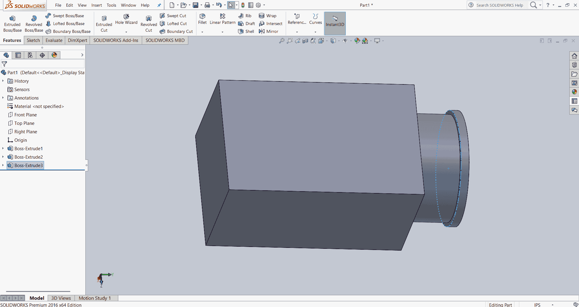
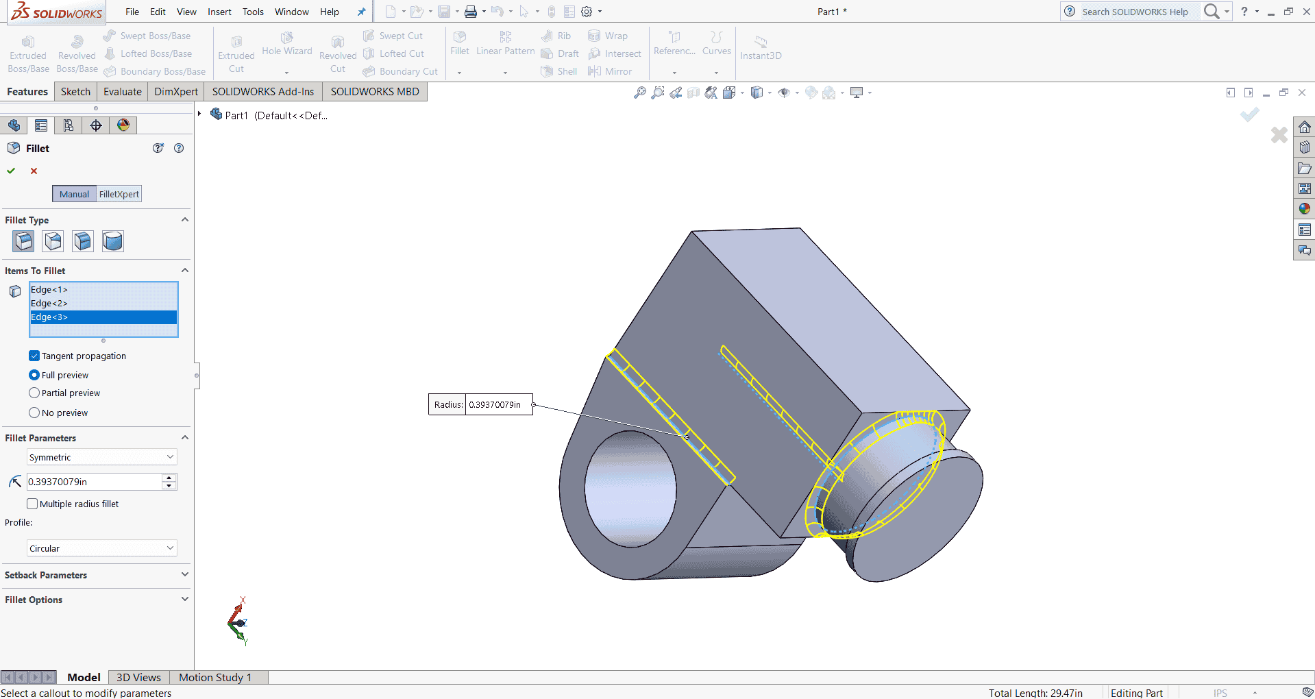
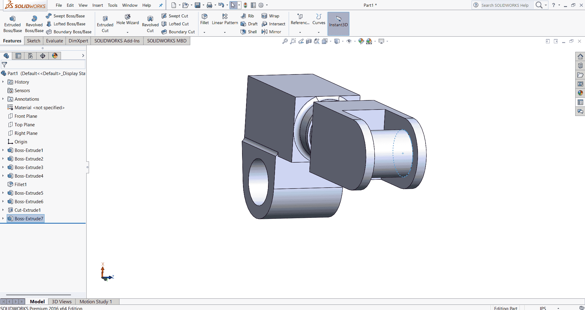
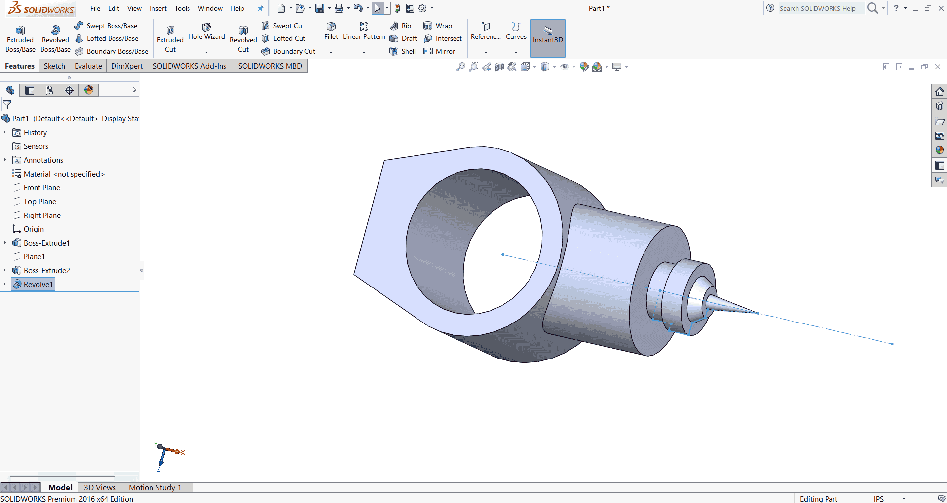
After completing the designs of Links 1 through 3, I proceeded to design the final component of the robotic arm: the end effector. The end effector is the part of the robotic arm that interacts directly with the environment, performing tasks such as gripping, welding, or painting.
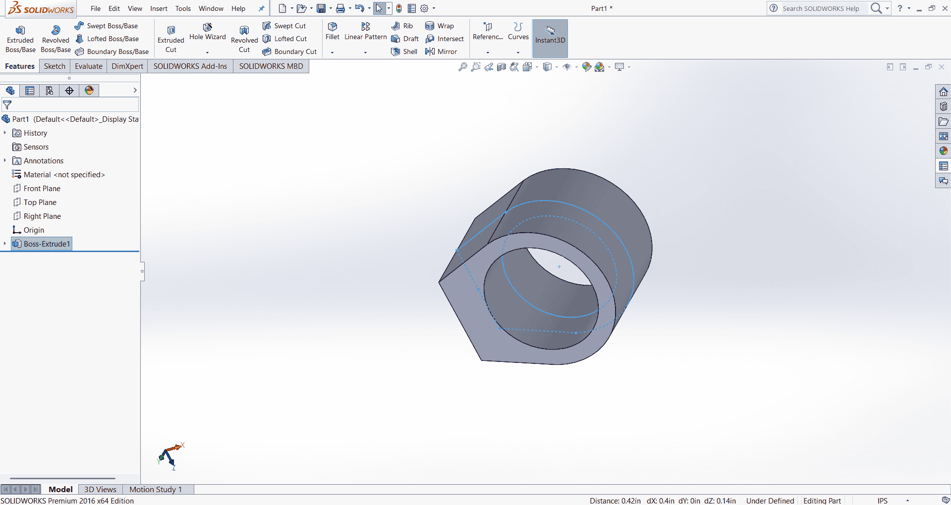
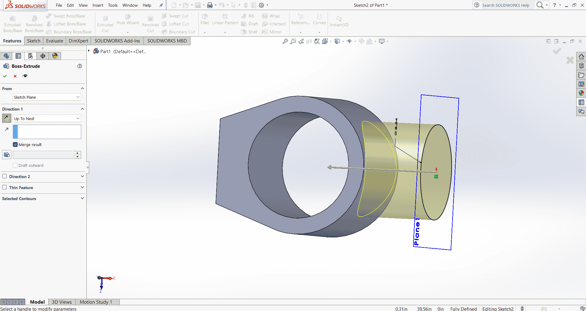
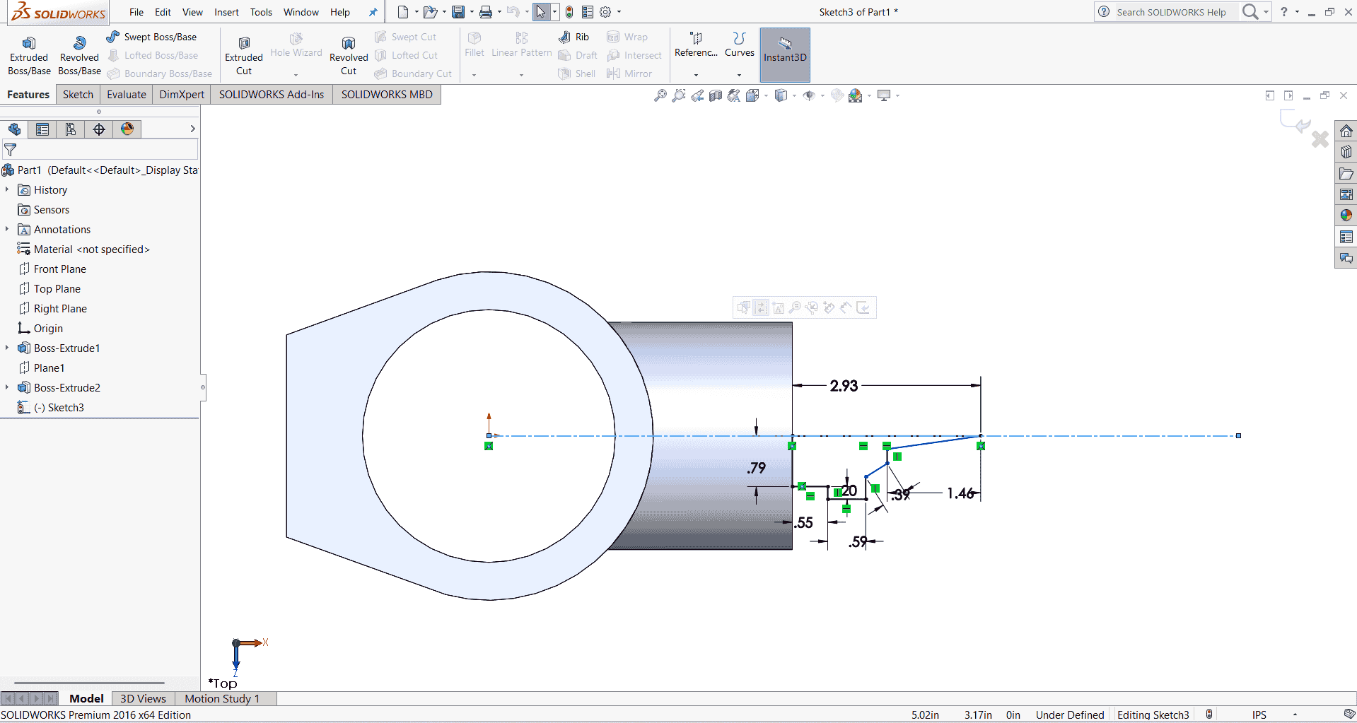
Assembling a robotic arm
After completing the designs of Links 1 through 4 and the end effector, I proceeded to assemble the robotic arm. This involved integrating all the individual components—base, links, and end effector—using appropriate mates to ensure proper alignment and movement. I also incorporated necessary actuators and sensors to enable the arm's functionality.Watch the Robotic Arm Assembly Video

Positive Outcomes:
In 2D Design: I explored various tools and applications, including open-source software, which offered a range of features. By effectively planning my schedule, I was able to practice and utilize different tools within the allocated time.
In 3D Design: I began with FreeCAD, referring to tutorial videos to create sketches and 3D objects. Transitioning to SolidWorks, I found its user interface more intuitive and efficient for my design needs.
In Image and Video Editing: I learned to use various applications, including shell commands and open-source cloud-based tools, enhancing my editing skills.
Challenges Encountered:
In 2D Design: I encountered installation issues with CorelDRAW on my computer, which required time to resolve. Subsequently, I switched to Inkscape to continue my work.
In 3D Design: I initially made several mistakes while assembling parts. However, I learned how to assemble parts in SolidWorks, which was easier. I need to learn complex motion study. Also, I could not spend more time on Fusion 360 and animation.
In Image and Video Editing: I made several attempts to reduce the file size of PNG images without compromising quality. Using the TinyPNG platform, I achieved satisfactory results.