Assignment 6: Electronics Design
For my Fab Academy 2025 Week 6 assignment on Electronics Design, I explored the basics of electronics, components, circuits, and test equipment. I learned how to use KiCad for PCB design and simulation. I designed my own PCB, starting with a simple schematic and component placement. I added an LED with a resistor to understand current-limiting and circuit behavior. Additionally, I included a push button as an input device to interact with the circuit. After designing the schematic, I routed the PCB traces efficiently. I then generated Gerber files for fabrication. This assignment helped me understand the workflow of PCB design, testing, and troubleshooting.
Highlight Moments of the Week
Basics of Electronics
Electronics is a branch of engineering and physics that focuses on designing and working with electrical circuits and components. It plays a key role in controlling and processing electrical signals to operate various devices efficiently. The flow of electric current through components like resistors, capacitors, transistors, and integrated circuits enables different functions in electronic systems. These systems are mainly classified into analog and digital, each used for different applications. Electronics is widely applied in communication, automation, computing, healthcare, and industrial sectors. Modern advancements, such as microcontrollers and embedded systems, have further improved electronic technology. Today, electronic devices power everything from smartphones and computers to medical equipment and aerospace technology. As technology continues to evolve, electronics remain a fundamental part of innovation, driving progress across multiple industries.
1. Fundamental Concepts
1.1 Electricity Basics
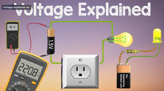
Voltage(V)
Voltage, also known as electric potential difference, is the force that pushes electric charge through a circuit. It is measured in volts (V) and represents the energy per unit charge. Higher voltage means a greater ability to move electrons, enabling electrical components to function properly. Voltage is supplied by sources like batteries, generators, and power outlets. It can be categorized into direct voltage (DC), where current flows in one direction, and alternating voltage (AC), where current changes direction periodically. In circuits, voltage differences between two points determine how much current flows. Proper voltage levels are essential to ensure the safe and efficient operation of electrical and electronic devices.
References: Reference#1
References: Reference#2
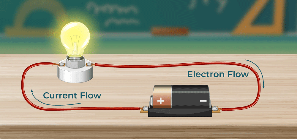
Current (I)
Electric current is the flow of electric charge through a conductor, such as a wire. It is measured in amperes (A) and represents the rate at which charge moves through a circuit. Current is driven by voltage, similar to how water flows through a pipe due to pressure. There are two main types of current: Direct Current (DC), where electrons flow in one direction, and Alternating Current (AC), where the direction of flow changes periodically. The amount of current in a circuit depends on the voltage and resistance, as described by Ohm’s Law (I = V/R). Managing current properly is crucial in electrical and electronic systems to ensure efficient operation and prevent damage to components.
References: Reference#1
References: Reference#2
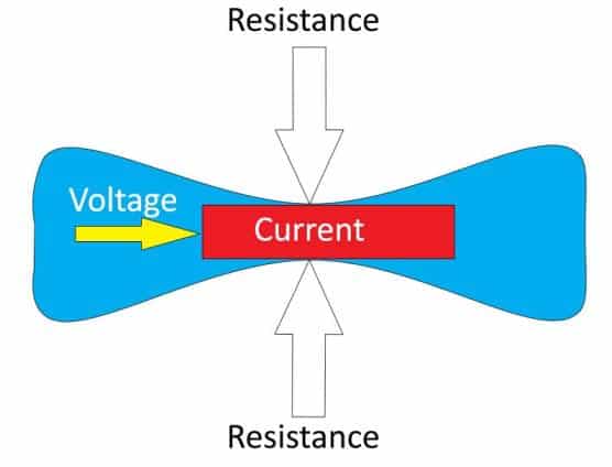
Resistance (R)
Resistance is the property of a material that opposes the flow of electric current in a circuit. It is measured in ohms (Ω) and determines how much current will flow for a given voltage. Materials like copper and silver have low resistance, allowing electricity to pass easily, while materials like rubber and plastic have high resistance, blocking the flow. Resistance depends on factors such as the material type, length, cross-sectional area, and temperature. Ohm’s Law explains the relationship between resistance, voltage, and current using the formula R = V/I, where R is resistance, V is voltage, and I is current. Resistors, which are electronic components designed to control current, are widely used in circuits to regulate voltage, protect components, and manage power distribution. Proper resistance selection is crucial for efficient and safe circuit operation.
References: Reference
Power (P) in Electrical Circuits
Electrical power is the rate at which energy is used or transferred in a circuit. It is measured in watts (W) and is calculated using the formula P = V × I, where V is voltage and I is current. Power determines how much work an electrical device can perform in a given time. In DC circuits, power remains constant, while in AC circuits, it can vary due to changing voltage and current. Power can be classified as active power (useful energy), reactive power (unused energy), and apparent power (total power supplied). Efficient power management helps reduce energy loss and ensures devices work safely. Understanding power is essential in designing electrical systems and selecting components for different applications.
P=V×I
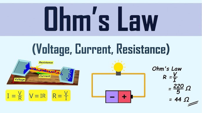
1.2 Ohm’s Law
Ohm’s Law explains the relationship between voltage, current, and resistance in an electrical circuit. It is given by the formula: V = I × R, where V is voltage (volts), I is current (amperes), and R is resistance (ohms). This means that voltage increases when current or resistance increases. Similarly, if resistance increases while voltage remains the same, the current decreases. Ohm’s Law helps in designing electrical circuits by determining the required voltage, current, or resistance. It is widely used in troubleshooting circuits and selecting components like resistors and fuses. Engineers use this law to prevent overloading and ensure safe electrical operation. Understanding Ohm’s Law is essential for working with electrical and electronic devices.
References: Reference
Kirchhoff’s Voltage Law (KVL)
Kirchhoff’s Circuit Laws help in analyzing electrical circuits with multiple connections. Kirchhoff’s Current Law (KCL) states that the total current entering a junction is equal to the total current leaving it. Kirchhoff’s Voltage Law (KVL) states that the sum of all voltages in a closed loop is always zero. These laws are based on the principles of charge and energy conservation. They are used to solve complex circuits by determining unknown currents and voltages. Engineers and electricians apply these laws in circuit design and troubleshooting.
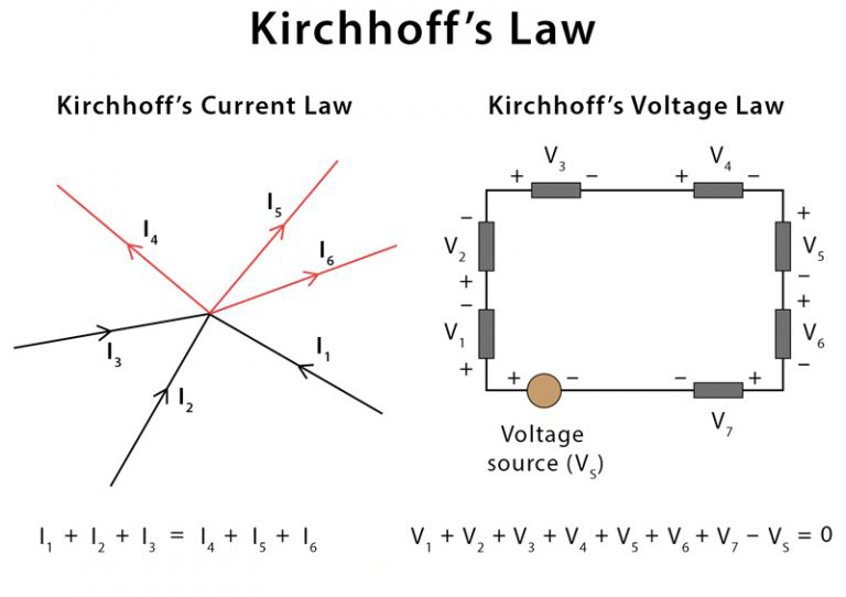
Kirchhoff’s Current Law (KCL) states that the total current entering a junction in an electrical circuit is equal to the total current leaving it. This follows the principle of charge conservation, meaning no charge is lost at the junction. It helps in analyzing circuits by ensuring current balance at connection points. KCL is widely used in designing and troubleshooting electrical and electronic circuits. This law is essential for solving complex circuits with multiple branches.
Kirchhoff’s Voltage Law (KVL) states that the sum of all voltages in a closed loop of an electrical circuit is always zero. This means that the total voltage gained in a loop is equal to the total voltage dropped. It follows the principle of energy conservation, ensuring that no energy is lost in an ideal circuit. KVL helps in calculating unknown voltages and analyzing complex circuits. Engineers use this law to design and troubleshoot electrical and electronic systems.
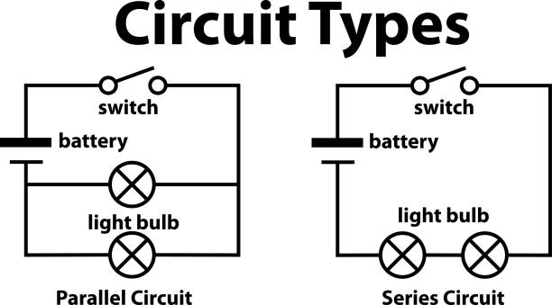
1.3 Types of Circuits
Series Circuit
A series circuit is a type of electrical circuit where all components are connected in a single continuous path. In this circuit, the same current flows through all components, but the voltage is divided among them.
The total resistance in a series circuit increases as more components are added, calculated as:
Rtotal = R1 + R2 + R3 + ...
The total voltage in the circuit is the sum of the voltages across each component:
Vtotal = V1 + V2 + V3 + ...
If one component fails, the entire circuit stops working. Series circuits are commonly used in devices like flashlights and decorative string lights.
Parallel Circuit Explanation
A parallel circuit is a type of electrical circuit where components are connected across the same voltage source, creating multiple paths for current to flow.
In a parallel circuit, each component receives the same voltage, but the current is divided among the branches. The total current is calculated as:
Itotal = I1 + I2 + I3 + ...
The total resistance in a parallel circuit decreases as more branches are added. It is calculated using:
1/Rtotal = 1/R1 + 1/R2 + 1/R3 + ...
If one component fails, the rest of the circuit continues to work. This makes parallel circuits ideal for home wiring and appliances, ensuring independent operation.
2. Electronic Components
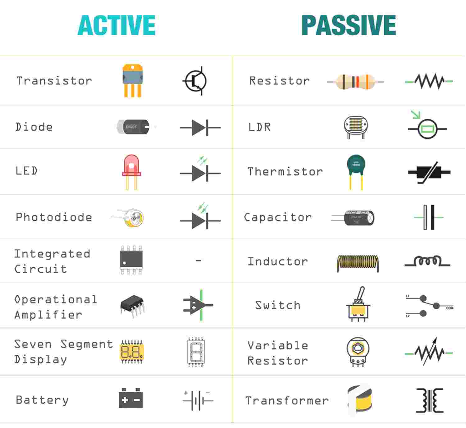
An electronic component is a physical part of an electronic system designed to influence the flow of electrical signals based on the system’s purpose. These components are typically connected within a circuit, often by soldering them onto a printed circuit board (PCB), to perform specific functions such as amplification, signal processing, or power regulation. Some components are standalone, while others are combined into complex integrated circuits (ICs)>. Common electronic components include resistors, capacitors, inductors, diodes, and transistors, each playing a vital role in circuit operation. Electronic components are generally classified into two types: active components like transistors and thyristors, which can control signal flow, and passive components like resistors, capacitors, and inductors, which do not require an external power source to function.
Difference Between Active and Passive Components
References: Reference
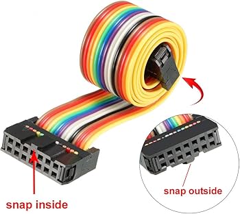
1. Ribbon Cable
ARibbon Cable is a flat, flexible cable with multiple parallel wires, commonly used in computers, printers, and electronic devices. Its organized structure allows for easy connections between circuit boards, drives, and display modules. The flexibility of ribbon cables helps them fit into compact spaces without tangling. Read More

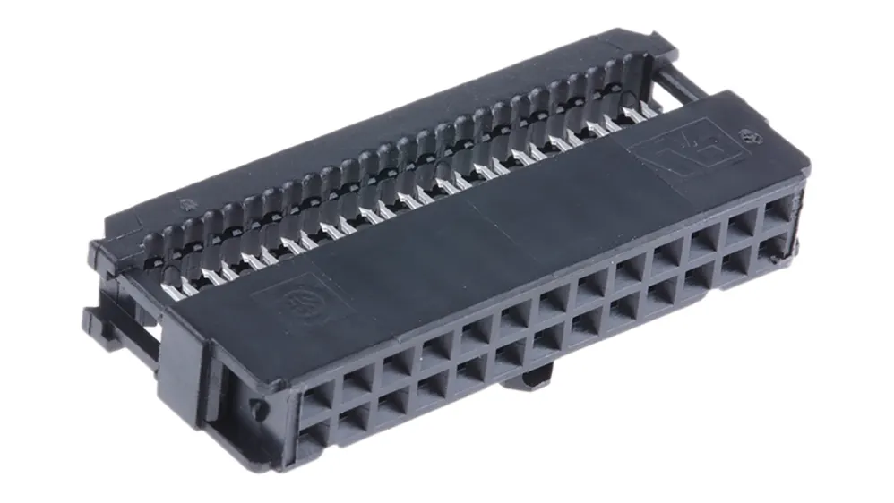
2. IDC Connector
An IDC (Insulation Displacement Connector) is a connector used to attach ribbon cables without stripping the wires. It has sharp metal contacts that pierce the insulation to create a secure electrical connection. IDC connectors are widely used in computers, telecommunications, and industrial equipment. Their quick and reliable design makes them ideal for multi-wire connections in compact spaces. These connectors help in reducing assembly time while ensuring strong and stable connections. Read More
|
|
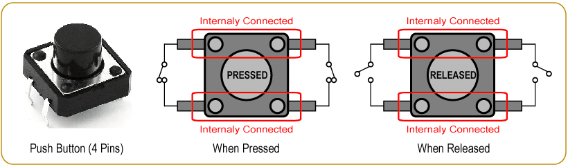
3. Push Buttons
A Push Button is a switch used to control electrical circuits by pressing and releasing it. It is commonly used in electronic devices, appliances, and industrial machines for turning functions on or off. Read More
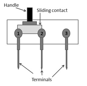
4. Switches
A Switch is an electrical device used to control the flow of current in a circuit by turning it on or off. It comes in various types, such as toggle, push-button, rocker, and rotary switches, depending on the application. Switches are widely used in home appliances, industrial machines, and electronic devices. They play a crucial role in controlling power and ensuring safety in electrical systems. Read More
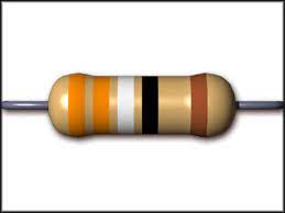
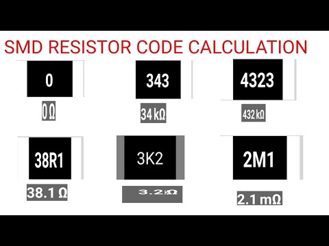
5. Resistors
A Resistor is an electronic component that limits or controls the flow of electric current in a circuit. It is used to reduce voltage, divide current, and protect components from excessive power. Resistors come in different types, such as fixed, variable, and thermal resistors, depending on their function. They are commonly found in electronic devices, power supplies, and circuit boards. Resistors play a vital role in stabilizing and regulating electrical signals within a system. Read More
|
|
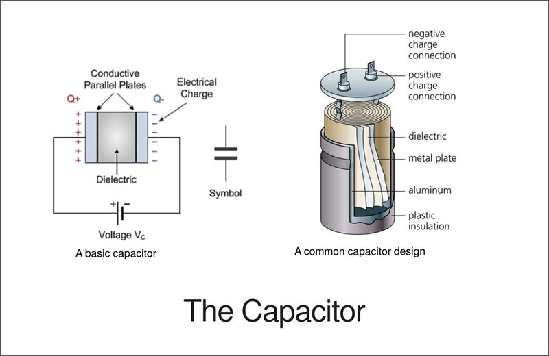
6. Capacitors
A Capacitor is an electronic component that stores and releases electrical energy in a circuit. It consists of two conductive plates separated by an insulating material (dielectric). Capacitors are used for filtering, energy storage, and signal processing in electronic devices. They come in various types, such as ceramic, electrolytic, and film capacitors, each suited for different applications. Capacitors help in smoothing voltage fluctuations and improving circuit performance. Read More

|
|
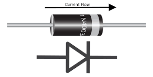
7. Diodes
A Diode is an electronic component that allows current to flow in only one direction while blocking it in the opposite direction. It is commonly used for rectification, signal processing, and voltage regulation in electronic circuits. Diodes come in different types, such as rectifier diodes, Zener diodes, and LEDs (Light Emitting Diodes), each serving specific functions. They play a crucial role in converting AC to DC, protecting circuits, and controlling signals. Diodes are widely used in power supplies, communication systems, and lighting applications. Read More
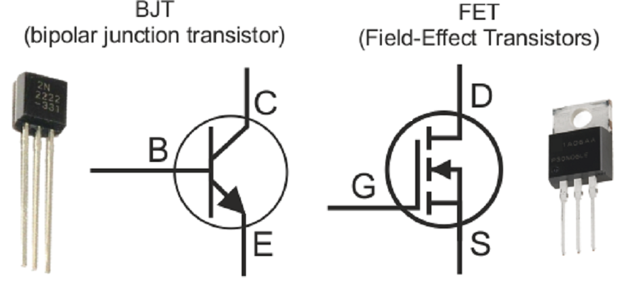
8. Transistors
A Transistor is a semiconductor device used to amplify or switch electronic signals in a circuit. It has three terminals—Emitter, Base, and Collector—that control the flow of current. Transistors are classified into Bipolar Junction Transistors (BJT) and Field Effect Transistors (FET) based on their working principle. They are essential in computers, communication devices, and power control systems. Transistors revolutionized electronics by enabling miniaturization and efficient circuit design.
9. Battery
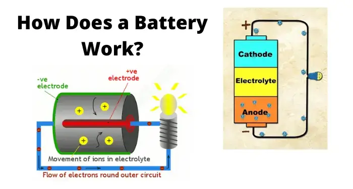
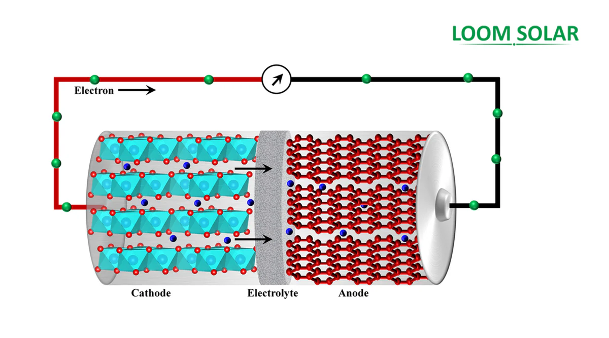
A battery is a device that generates electrical energy through one or more electrochemical cells. It has external terminals that connect to circuits, providing power to electronic devices. In simple terms, a battery stores and supplies electricity when needed.
When a battery is in use, the positive terminal (cathode) and the negative terminal (anode) create a flow of electrons through an external circuit. The negative terminal releases electrons, which travel through the connected device and return to the positive terminal. This movement of electrons is driven by a redox (reduction-oxidation) reaction, where chemical energy is transformed into electrical energy. Originally, the term "battery" referred to a group of multiple cells working together, but today, even a single-cell power source is commonly called a battery.
|
|
References: Reference#1, Reference#2, Reference#3
10. DC Voltage Regulators
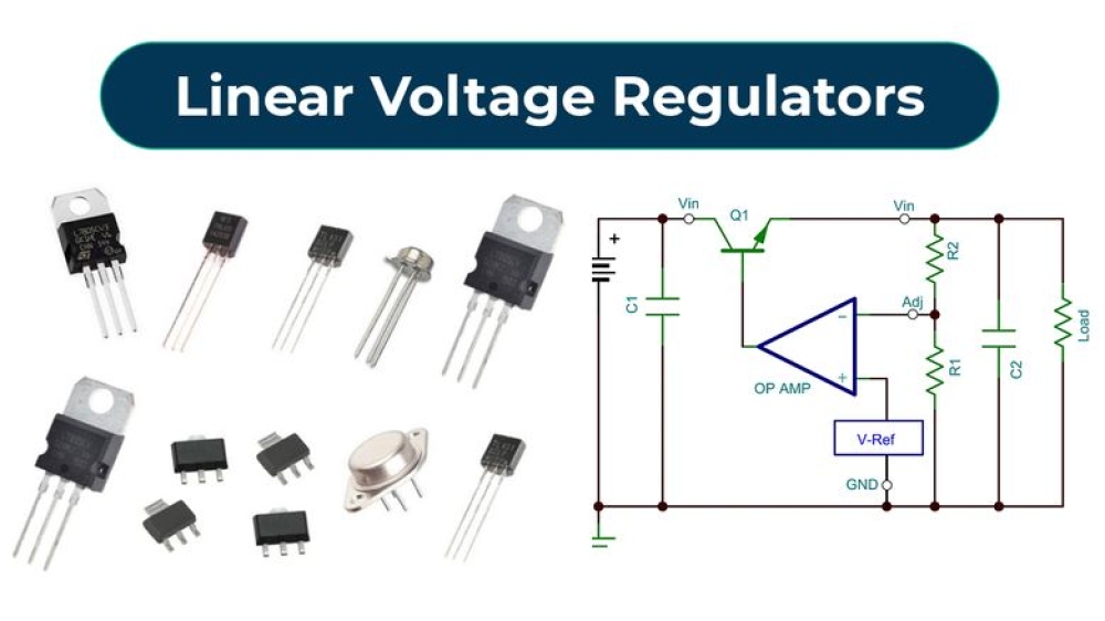
A DC voltage regulator is an electronic component that maintains a stable DC output voltage regardless of input fluctuations or load variations. It ensures that circuits receive a consistent voltage, preventing damage to sensitive components.
There are two main types: linear regulators, which dissipate excess energy as heat, and switching regulators, which convert power efficiently using high-frequency switching. Common regulators include LM7805 (5V), LM317 (adjustable), and buck-boost converters for variable voltage needs. These regulators are essential in microcontroller circuits, motor controllers, and power supply systems to ensure reliable operation.
References: Reference, More Information
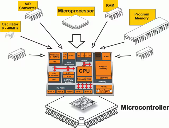
11. Microcontroller
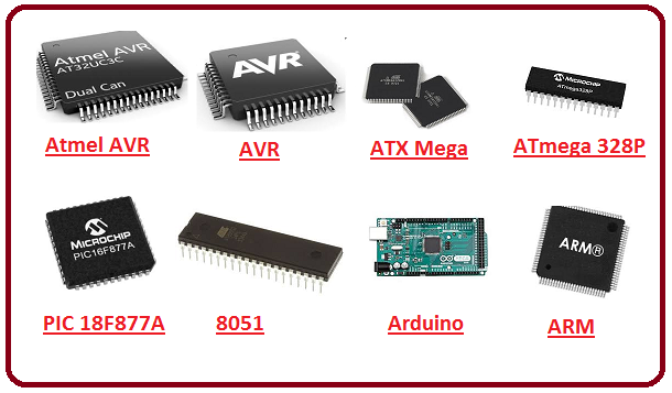
A microcontroller is a compact integrated circuit that functions as a small computer, designed to control electronic devices. It consists of a processor (CPU), memory (RAM, ROM), and input/output (I/O) ports on a single chip.
Microcontrollers execute pre-programmed instructions to automate tasks in embedded systems. They are widely used in robotics, home automation, industrial control, and IoT devices. Popular microcontrollers include Arduino (ATmega328), ESP32, and STM32, each suited for different applications.
|
|
References: Reference#1, Reference#2
Different between microcontroller microprosser

References: Reference
12. sensor
A sensor is a device that detects and measures physical changes in the environment, such as temperature, light, motion, or pressure. It converts these changes into electrical signals, which are processed by a microcontroller for automation and control.
13. Actuators
An actuator is a device that converts electrical signals into physical movement, enabling automation in mechanical systems. It can control motion using motors, solenoids, or pneumatic and hydraulic systems.
I took the help of ChatGPT to understand the above expansion for my own learning and further exploration.ChatGPT
Group Assignment
Objective of the Group Assignment:
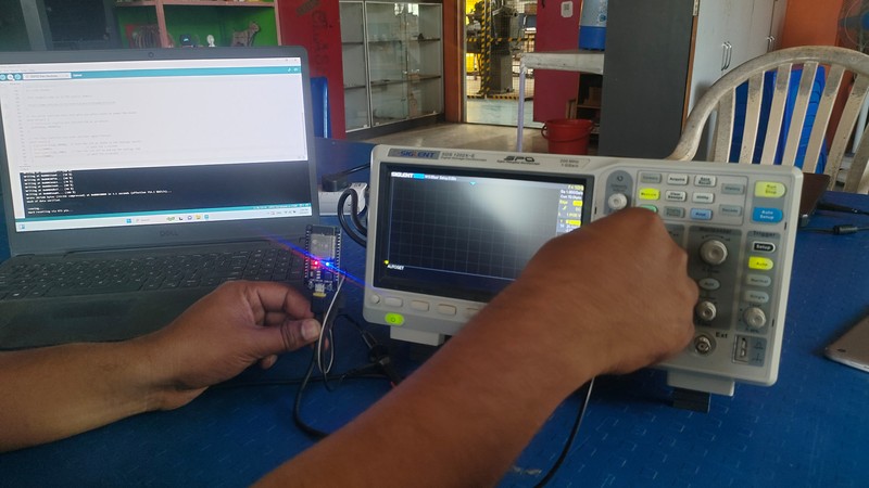
- Use the test equipment in your lab to observe the operation of a microcontroller circuit board,
- Demonstrate the use of a multimeter and oscilloscope
- Document your work on the group work page and reflect on your individual page
Test Equipments
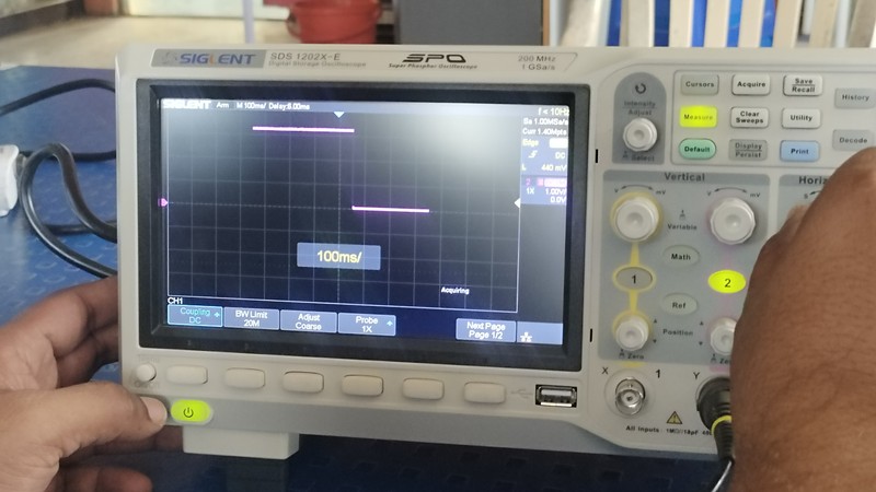
oscilloscope - Oscilloscope displays electrical signals as waveforms, showing how voltage changes over time.It allows you to visualize and analyze the shape, amplitude, frequency, and other characteristics of these signals.
Work -
- Debugging electronic circuits.
- Analyzing signal integrity.
- Measuring signal frequency and amplitude.
- Troubleshooting power supply ripple and noise.
- Viewing digital and analog signals.
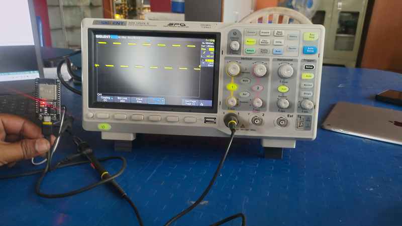
Oscilloscope
Multimeter -
Multimeter measures various electrical properties, primarily voltage, current, and resistance. It's a versatile tool for basic electrical measurements.
Work -
- Measuring voltage (AC and DC).
- Measuring current (AC and DC).
- Measuring resistance.
- Checking continuity (whether a circuit is complete).
- Troubleshooting basic electrical problems.
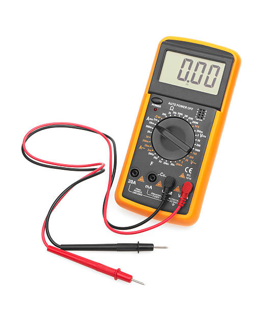
Multimeter
Power Supply -
Power supply provides a stable and controlled source of electrical power. It typically converts AC power from a wall outlet to DC power needed by electronic devices.
Work -
- Providing power to electronic circuits during testing and development.
- Powering electronic devices.
- Testing device functionality under varying voltage and current conditions.
- There are many different types of power supplies, with varying levels of complexity, and control. Power supplies are what provide the electricity for the circuits that you are working on.
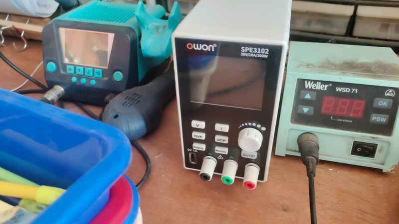
Power Supply
Testing equipments in the Lab
Oscilloscope

|

|

|
|
|
Individual Assignment
Objective of the Individual Assignment:
-Use an EDA tool to design a development board
-Ensure the design uses parts from the inventory to interact and communicate with an embedded microcontroller
Free and Open-Source PCB Design Software:
KiCad -is a powerful open-source PCB design software that includes schematic capture, PCB layout, and 3D visualization tools. It is widely used by hobbyists and professionals for designing complex circuit boards with full customization.
EasyEDA - is a web-based PCB design tool that offers schematic capture, circuit simulation, and PCB layout in a single platform. It is user-friendly and integrates seamlessly with PCB manufacturing services, making it ideal for both beginners and professionals.
Fritzing - is an open-source PCB design and prototyping tool aimed at beginners and educators. It provides an intuitive interface for creating circuits, breadboard layouts, and PCB designs, making it easier to transition from prototyping to manufacturing.
LibrePCB - is a free and open-source PCB design software focused on simplicity and ease of use. It offers an intuitive workflow for schematic capture and PCB layout, making it accessible to both beginners and experienced designers.
My PCB Design Journey Using KiCad for This Assignment :
My PCB Design Journey Started with KiCad Because of Its Flexibility and
Open-Source & Powerful – KiCad is a free, open-source PCB design suite with professional-grade features.
Schematic & PCB Layout – It provides schematic capture, PCB layout, routing, and design rule checking (DRC).
3D Visualization – Allows users to preview PCBs in 3D before manufacturing.
Custom Libraries & Gerber Export – Supports custom footprints, symbols, and easy Gerber file generation for fabrication.
Downloading KiCad
First, I started by downloading KiCad If you want to download it, please click click here., here.After opening the official KiCad website, go to the download page and select the version for your operating system. In my case, I chose the Windows version.

|

|
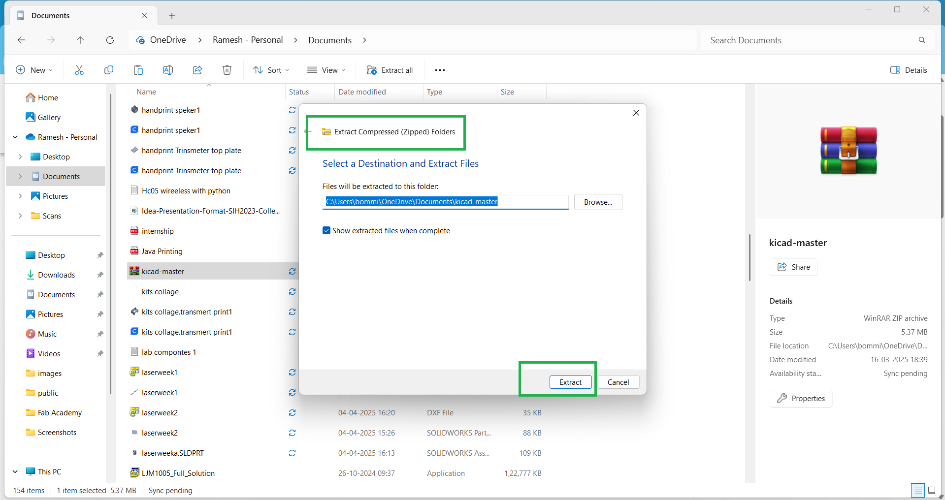
After selecting the version, click on GitHub as shown in the image below. Once clicked, the download will start immediately. After the download is complete, go to the file location, extract the file, and install it.

|
|
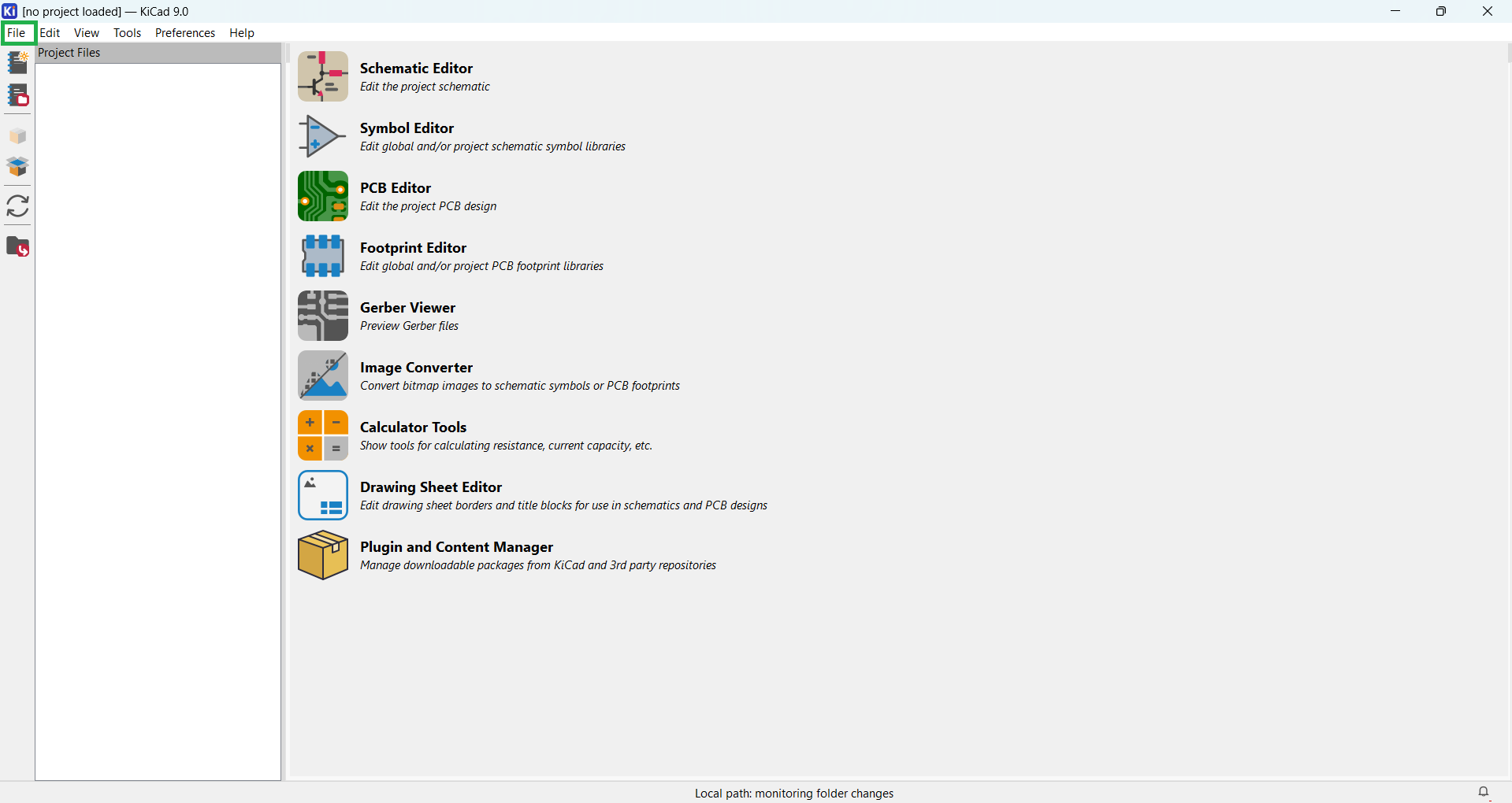
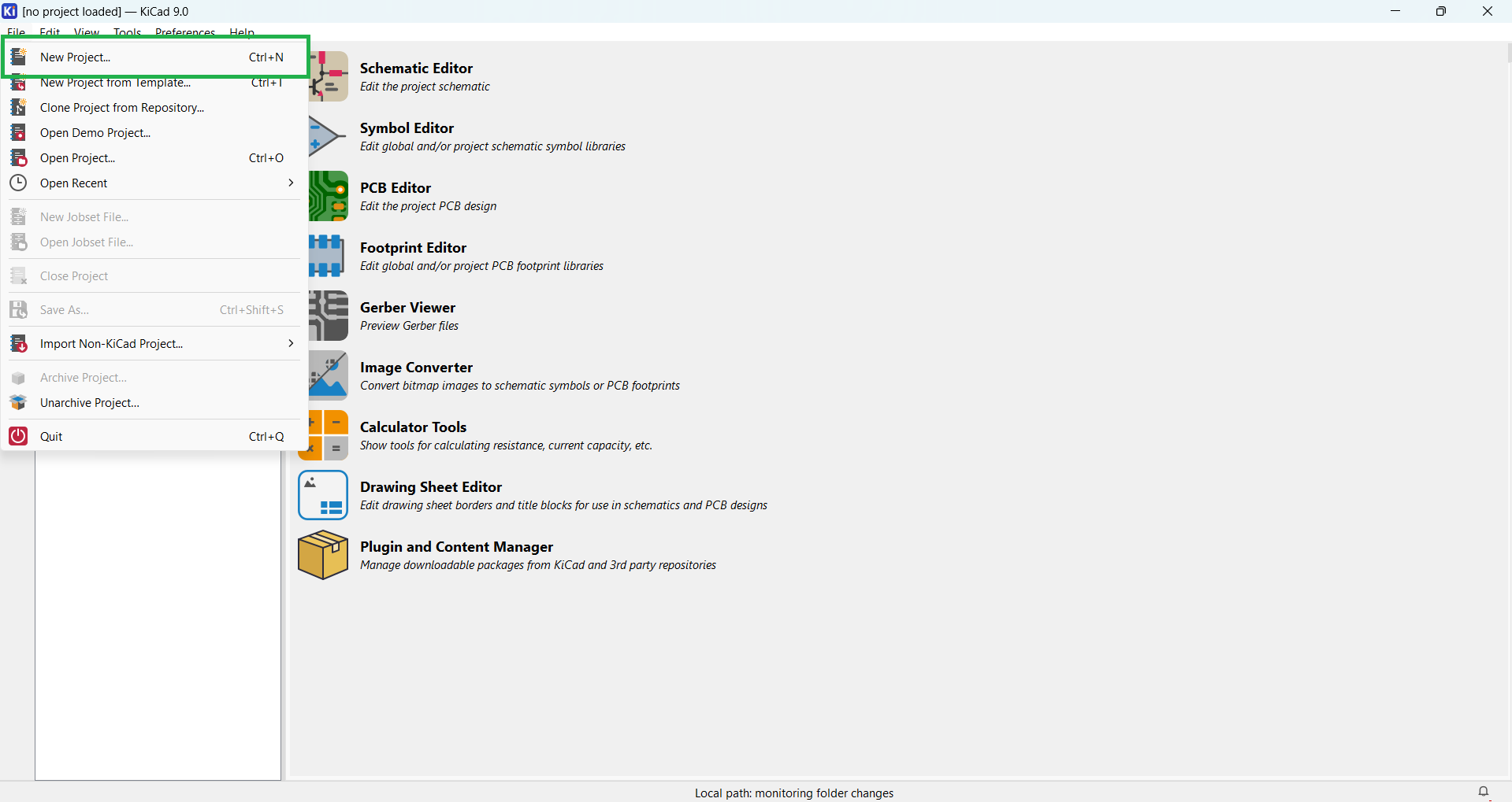
After completing the installation, open KiCad, go to the File menu, and select "New Project" to create a new project.
|
|
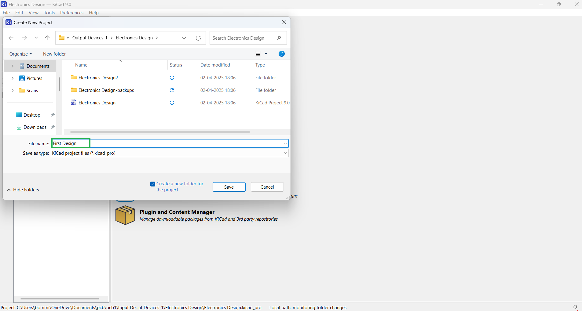
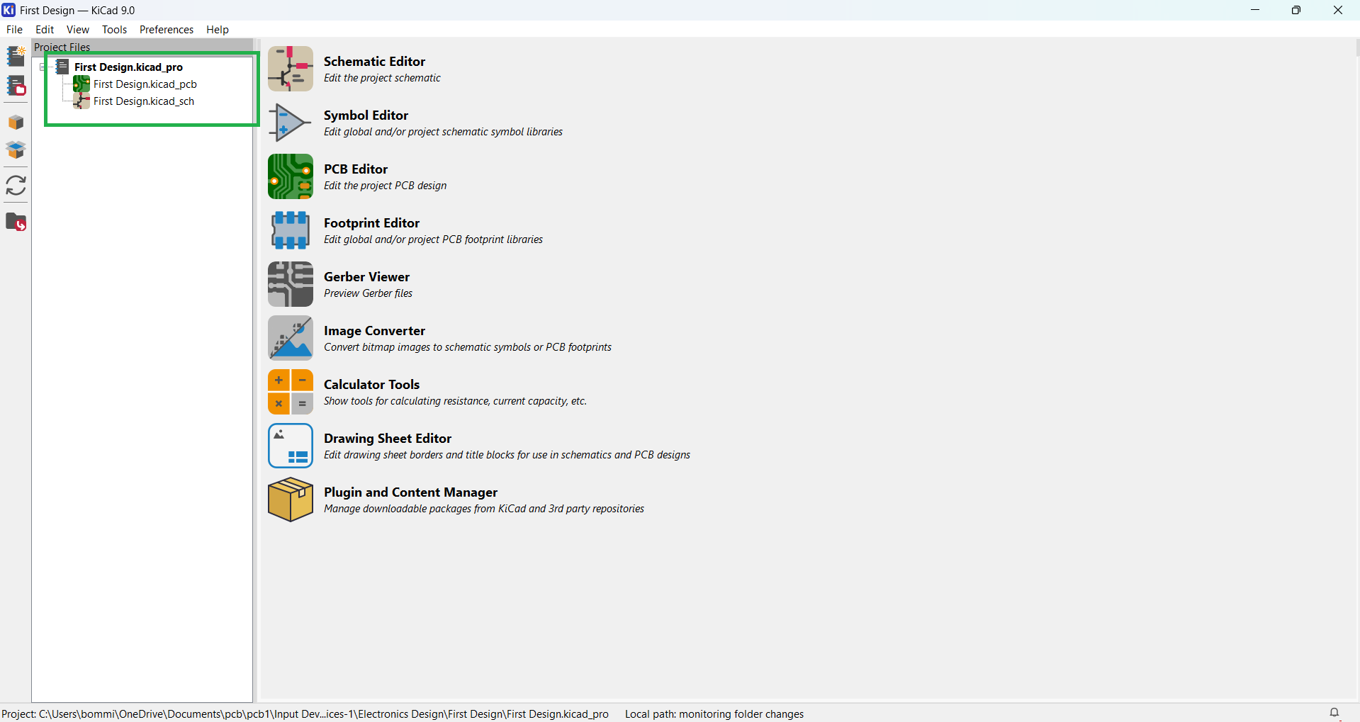
Give a name to your project and choose the file location where it will be saved. Then, click on "Create File." After clicking, you will see two files: one is the schematic file, and the other is the PCB file.
|
|
Then, open the schematic file to start designing your circuit.
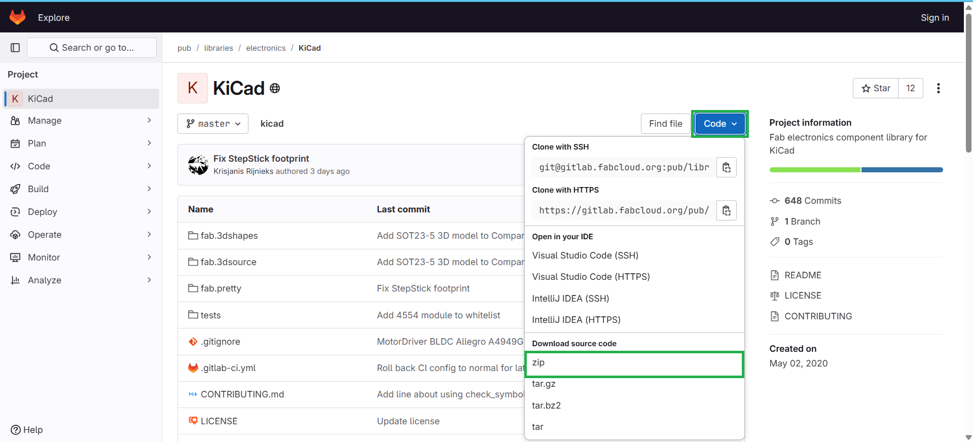
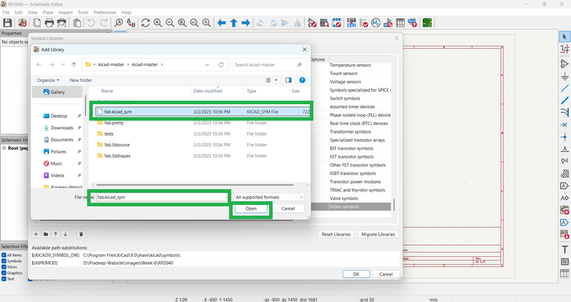
Before beginning the design, you need to add the Fab libraries in your KiCad software.
click here.,
to download the libraries and follow the steps below to install them..
|
|
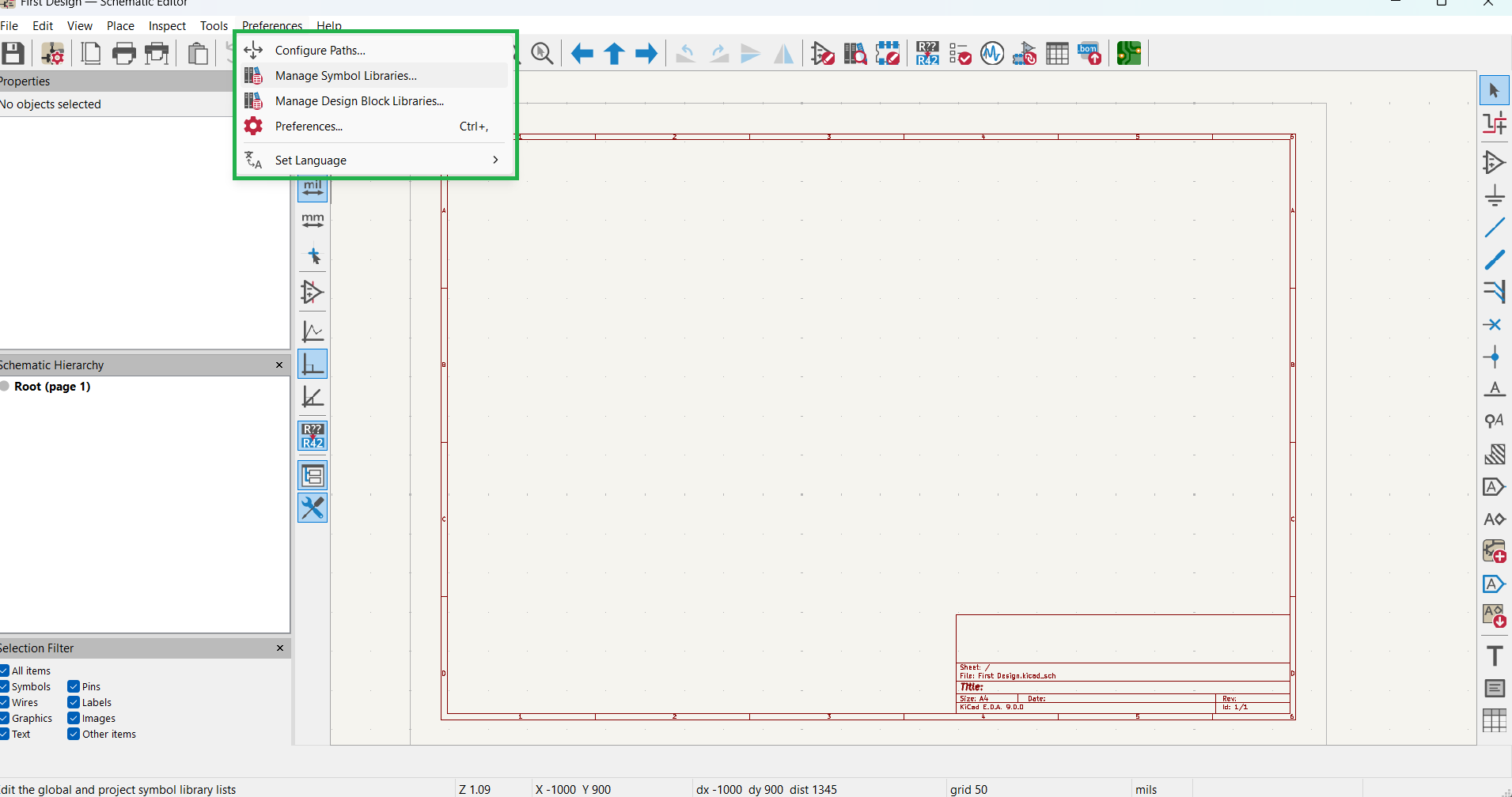
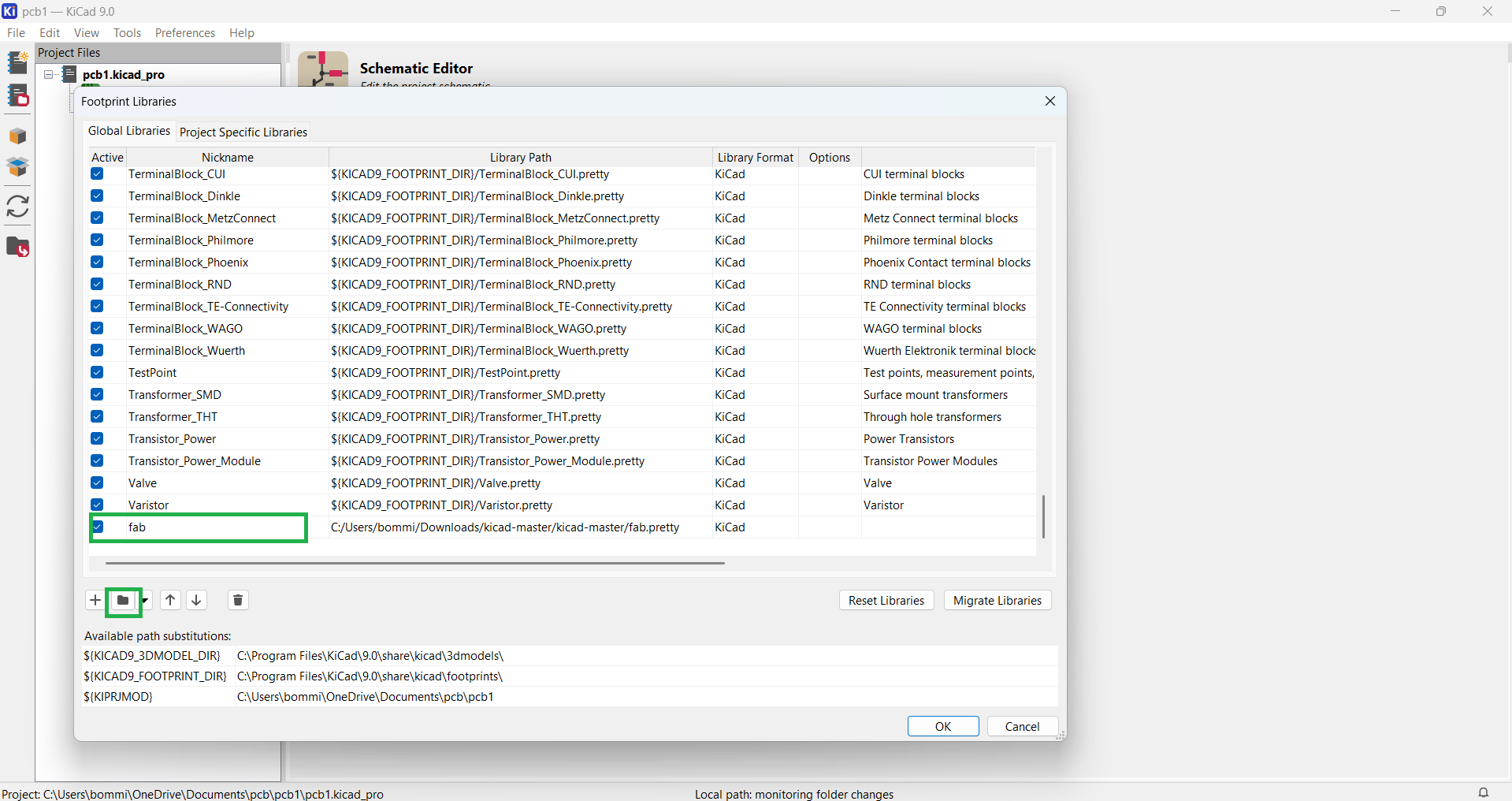
AFTER Complitig of dowloding libries open kicad software go to preferancess ther you find the mange symble libryres and mangedesign block librayes first clike on symble librys and add it than after adding agen repit the process for adding desig block libreres write in correct way
|
|
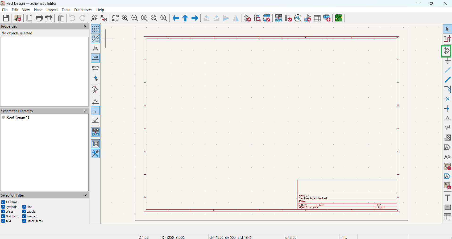
Now that the library addition process is complete, I have started designing my PCB.
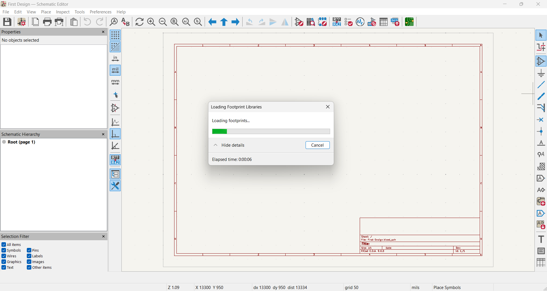
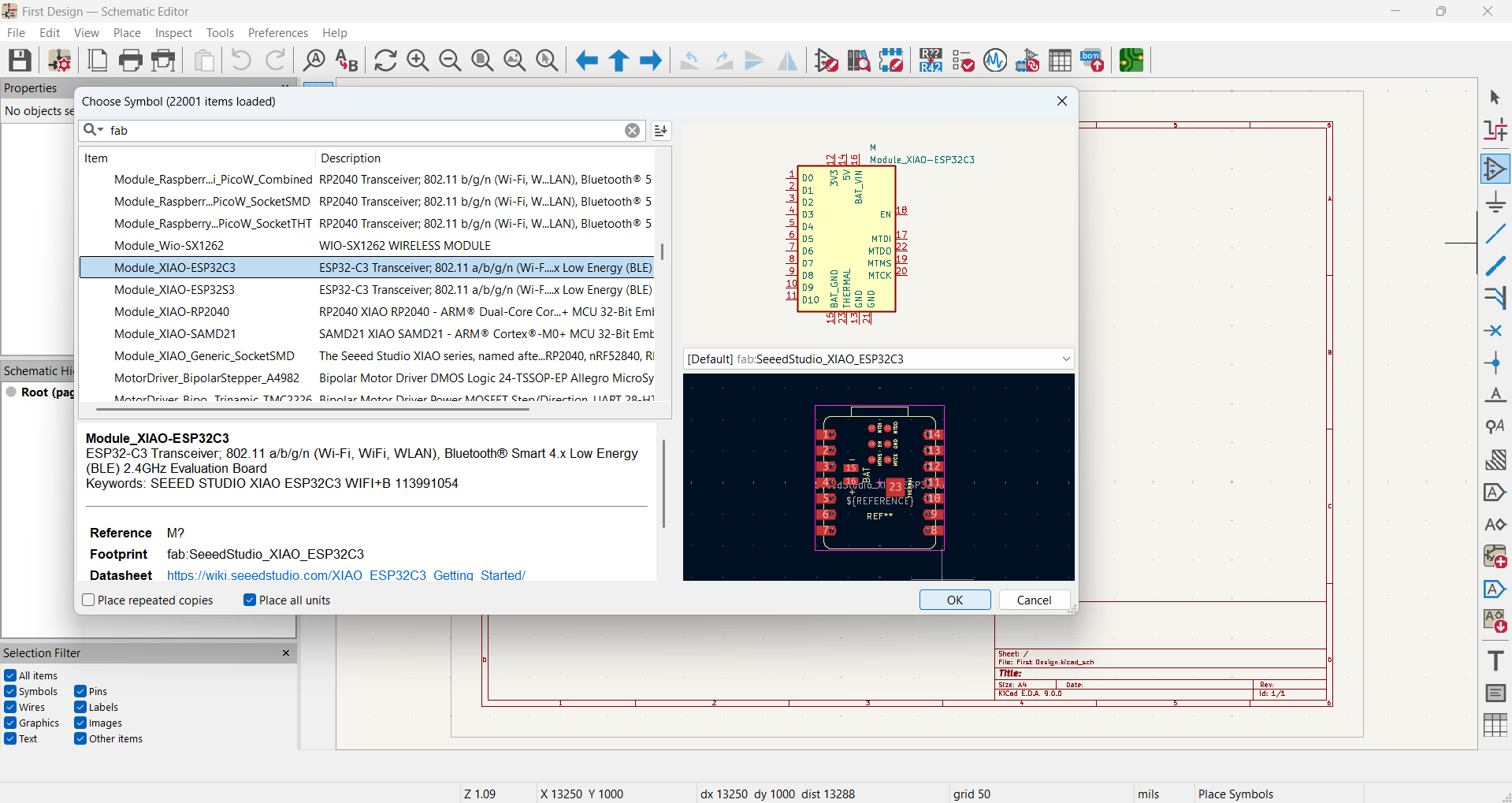
To do this, I go to Symbols, select the required components, and add them to the schematic sketch. In the image below, you can see the footprints loading.
|
|
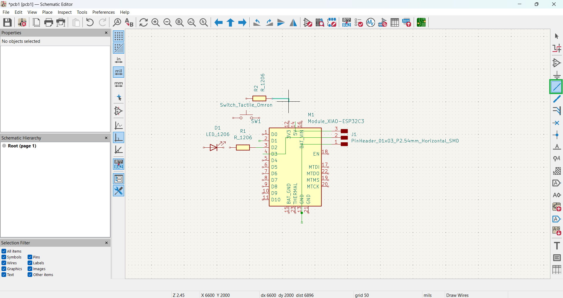
For my Electronics Design week, I am using an ESP32-C3 microcontroller. Along with it, I have added one push button, one LED, and a 4-pin header for additional requirements. The 4-pin header is connected to VCC, GND, and SDA SCL of my microcontroller.
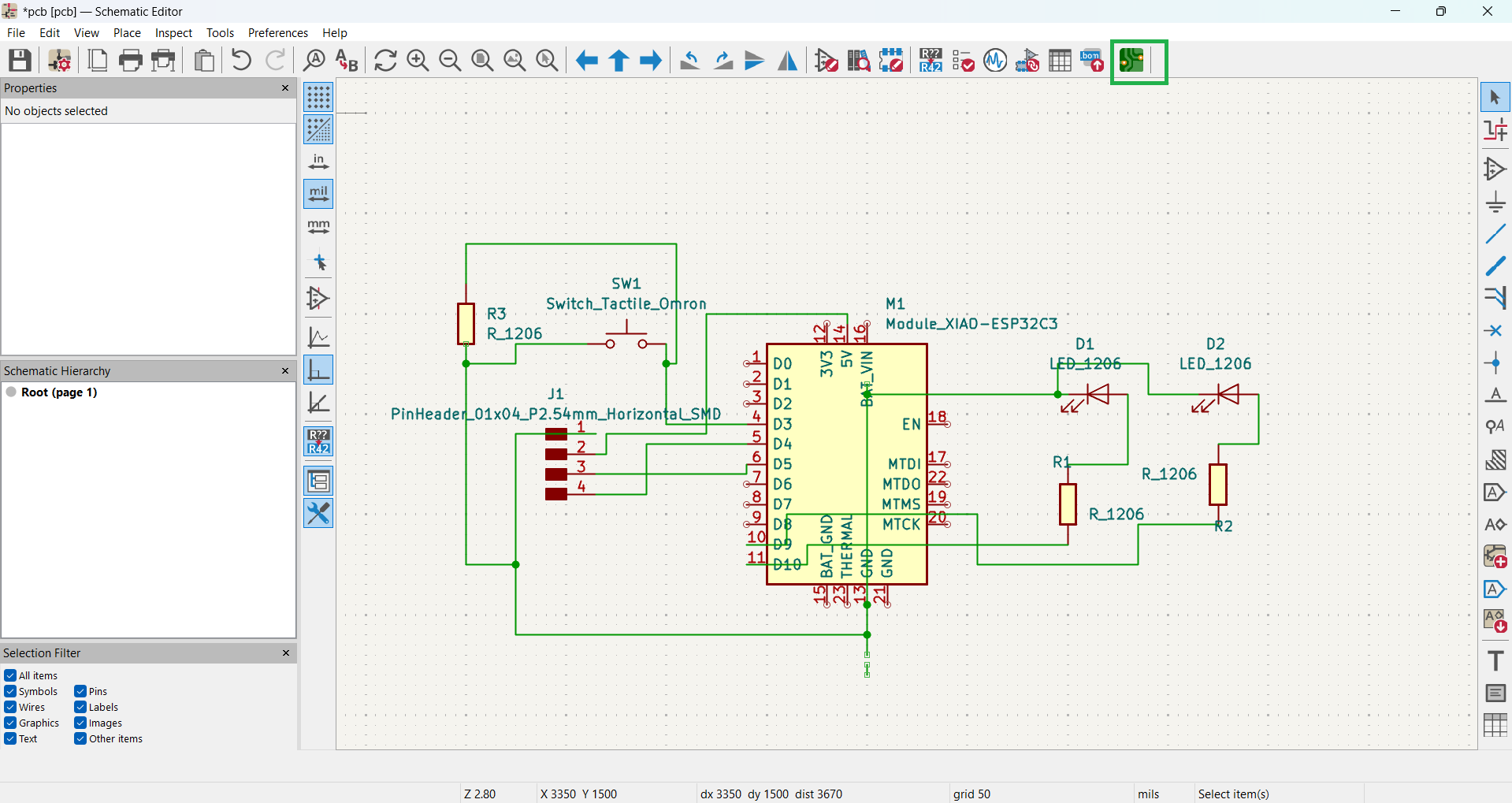
To connect the circuit, I used the Wire Tool for proper connections. In the image below, you can see the wiring setup.
|
|
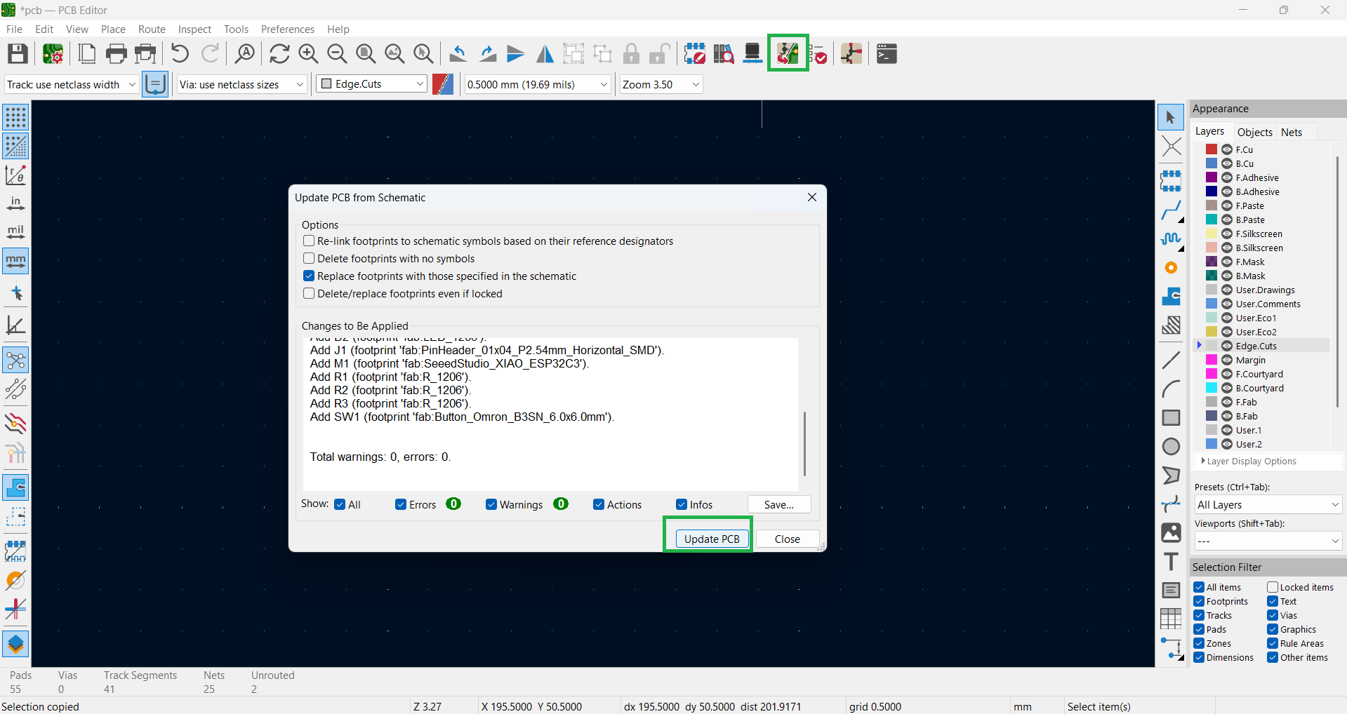
I have completed all the connections as per my requirements. After that, I clicked on "Switch to PCB Editor", and then I clicked the "Update PCB from Schematic" button, as shown in the figure, to update the PCB layout.
|
|
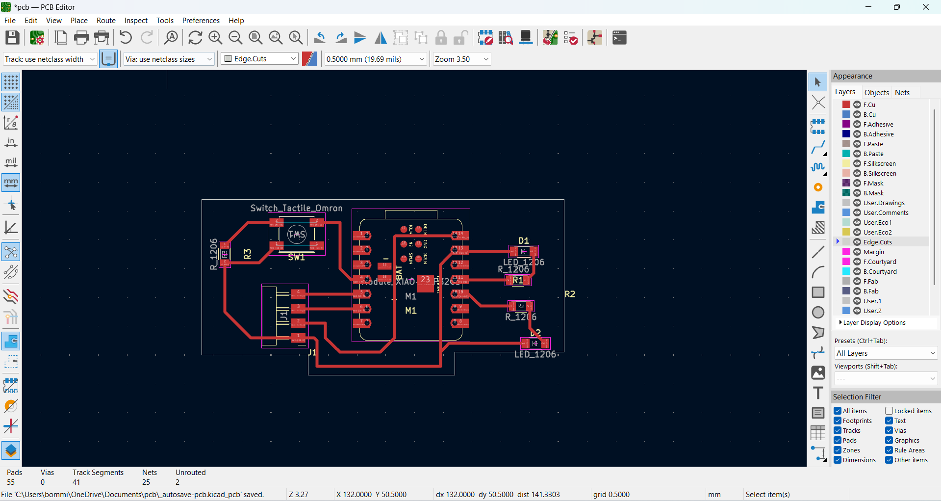
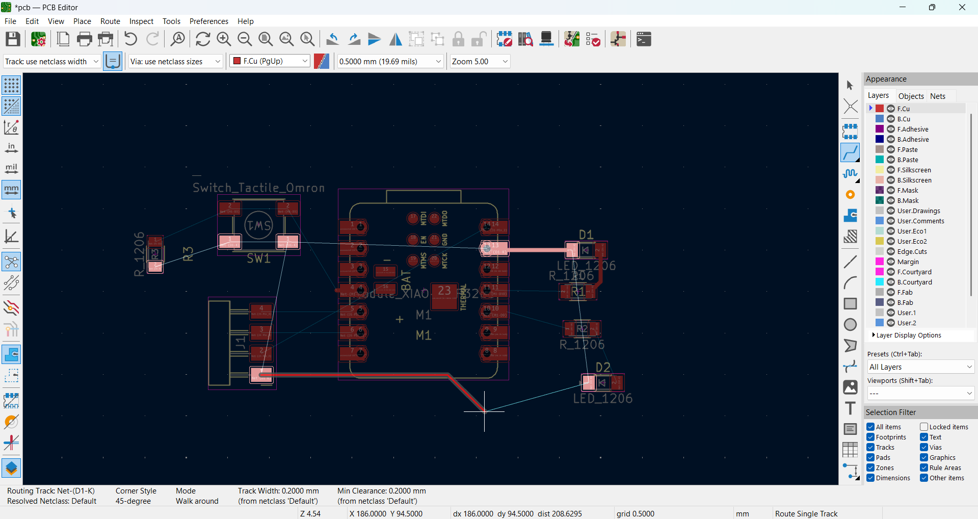
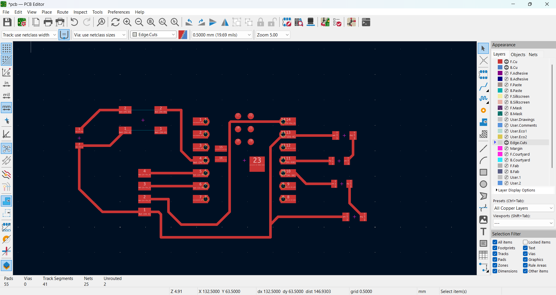
After completing the PCB update, I arranged the components according to my requirements. Then, I started drawing the route tracks, as shown in the image.
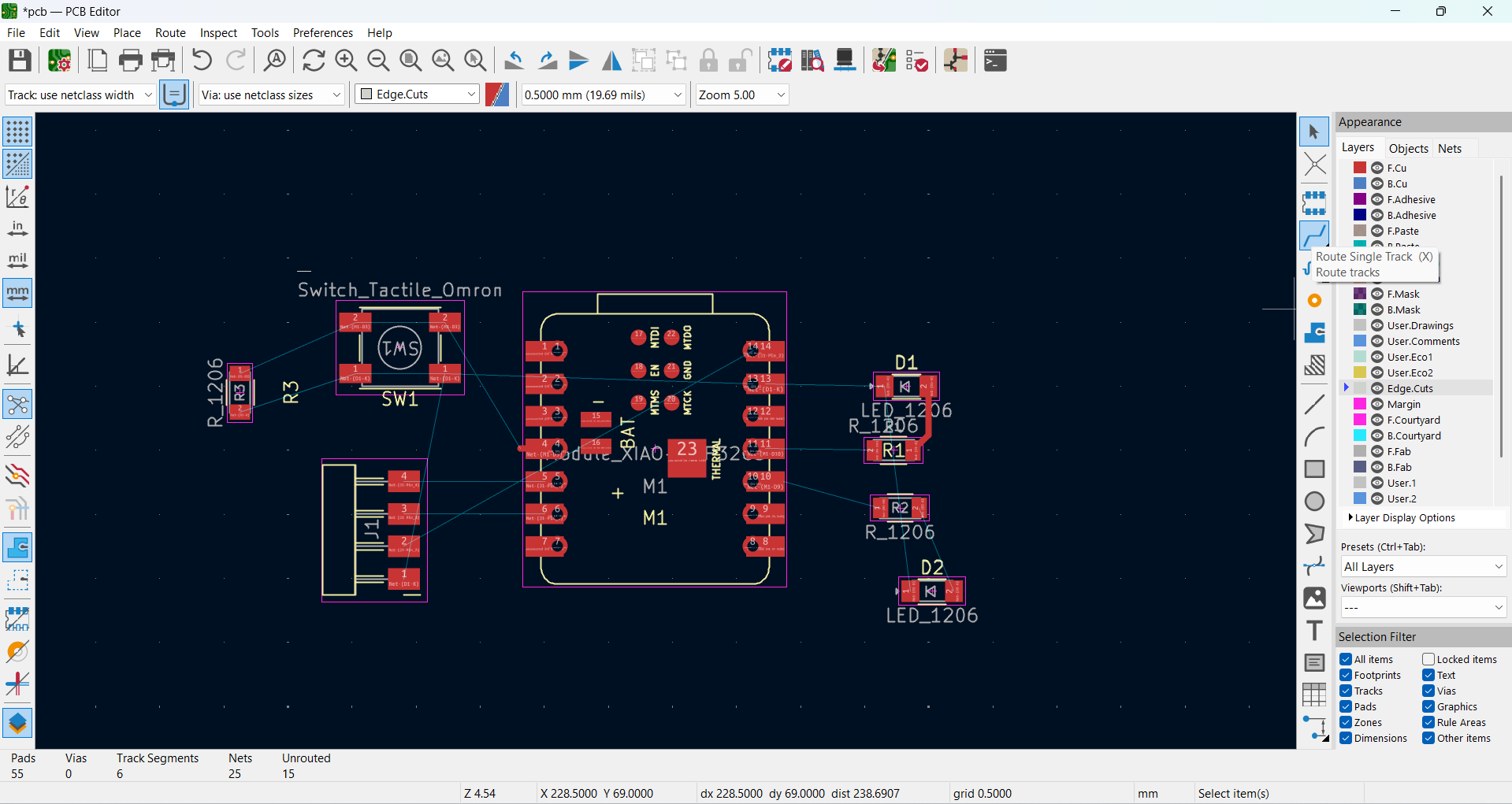
|
|
After completing all the route tracks, I selected the Edge Cut to define the PCB boundary, as shown in the image.
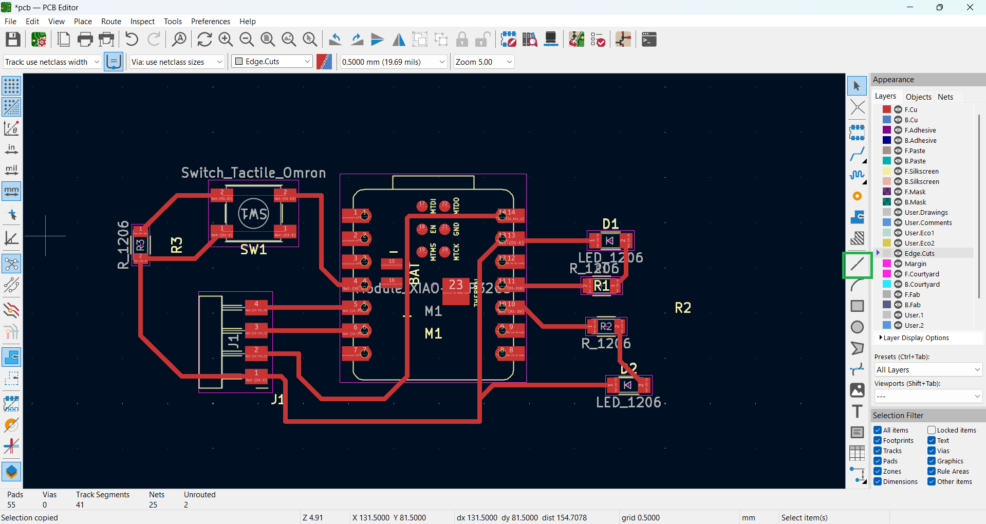
|
|
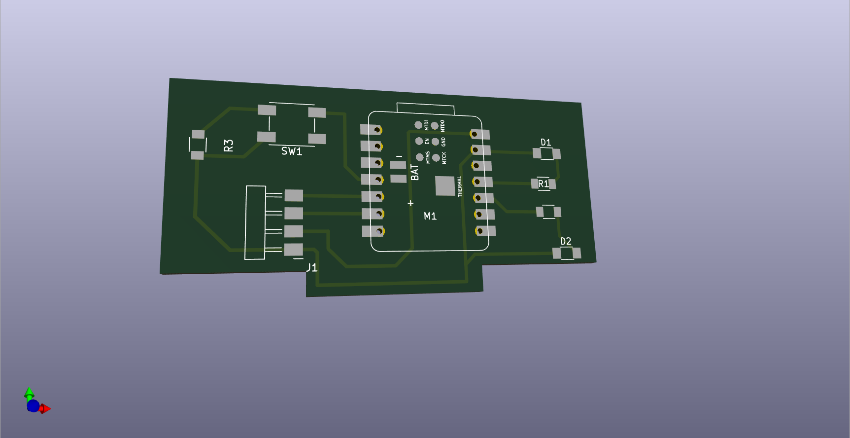
After completing the Edge Cut, below, I am showing all the copper layers of my PCB along with the 3D view of my PCB.
|
|
Positive Outcomes:
This week, I learned the basics of electronics and the difference between a microcontroller and a microprocessor. I also explored various PCB design software tools and understood their applications.
I gained hands-on experience in designing a PCB using KiCad and experimented with different footprints. While working on my design, I learned how to properly use schematic symbols, routing, and PCB layout techniques.
Additionally, I explored how to add libraries in KiCad and effectively manage components. Through trial and error, I improved my understanding of PCB design rules and best practices.
This experience helped me build confidence in creating and modifying circuit designs. Overall, I enjoyed the learning process and felt excited to explore more about electronics and PCB design.
I am very happy this week as I discovered and practiced new skills in PCB design! 😊
Challenges Encountered:
This week, I faced issues with designing the PCB because it was my first experience with KiCad. After updating the PCB, I felt confused about how to arrange all the components properly on my board.