Assignment 10: Output Devices
This assignment focuses on documenting my learning about output devices, including their types, working principles, and how to interface them with various microcontroller boards, including the one I designed for this week. I have detailed the design process of my board, ensuring compatibility with specific output devices I intended to use. Additionally, this assignment marked the beginning of designing a dedicated board for the output week. My goal is to utilize this board to connect and test the output devices required for my final project.
I successfully designed, fabricated, and programmed one board to control output devices. Moreover, I have reflected on the successes, challenges encountered, areas for improvement in future assignments, and key lessons learned from this experience.
Highlight Moments of the Week
|
|
|

|
Basics of Output Devices
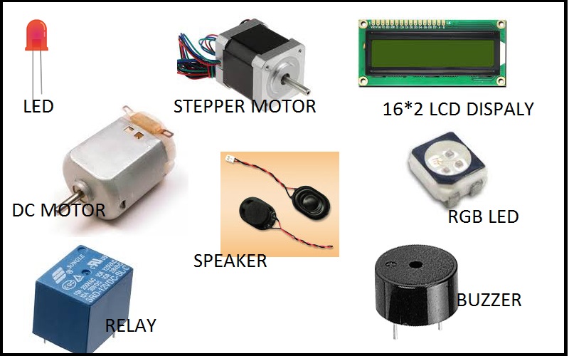
An output device is a hardware component that receives signals from a microcontroller and converts them into a perceivable form like light, sound, motion, or heat. Common examples include LEDs, LCDs, OLEDs, and TFT displays for visual output, while buzzers and speakers generate sound. DC motors, servo motors, and stepper motors enable movement, whereas heating elements and Peltier modules regulate temperature. Relays act as electronic switches for high-power control, and haptic actuators provide vibration feedback. These devices operate using digital signals, PWM, or analog control, with some requiring I2C, SPI, or UART for communication. Output devices can function independently or work with sensors to respond to external inputs. They are essential in embedded systems, enabling machines to interact with the physical world.
References: Reference
Before documenting my work for this week's output devices assignment, I will first provide an overview of some common output devices. These include LEDs, LCDs, OLEDs, and TFT displays for visual output, buzzers and speakers for sound, and motors, relays, and heating elements for motion and temperature control.
Types of Output Devices
Output devices can be classified into different types based on the type of output they generate:
1. Visual Output Devices
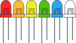
1.1 LEDs (Light Emitting Diodes):
LEDs (Light Emitting Diodes) are small semiconductor devices that emit light when an electric current passes through them. They are energy-efficient, long-lasting, and come in various colors and sizes. LEDs are commonly used for indicators, displays, and lighting applications in electronics. They operate on low voltage and can be controlled using microcontrollers with simple digital or PWM signals. Due to their reliability and versatility, LEDs are widely used in everything from household lighting to advanced display systems. for More information
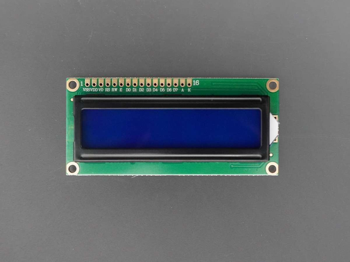
1.2 LCD (Liquid Crystal Display):
LCD (Liquid Crystal Display) is a flat-panel display technology that uses liquid crystals to control light and produce images. It works by blocking or allowing light to pass through different segments when an electric current is applied. LCDs are commonly used in devices like watches, calculators, monitors, and display screens. They consume less power compared to older display technologies like CRTs, making them ideal for battery-powered devices. LCDs come in various types, including monochrome, alphanumeric, and full-color displays used in televisions and smartphones. for More information
References: Reference
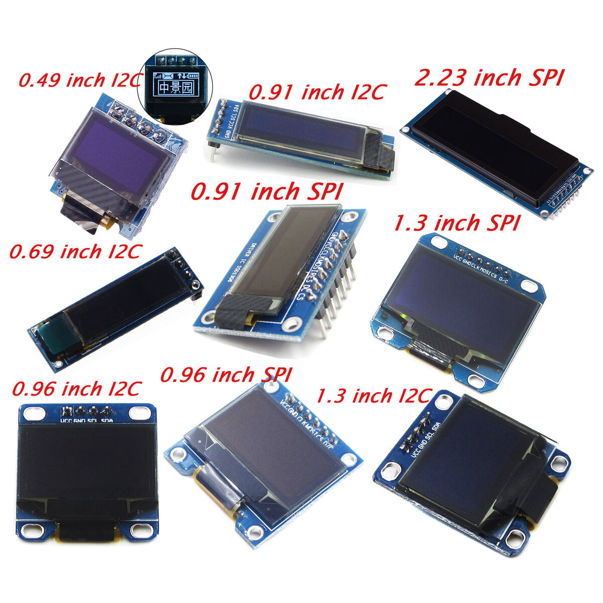
1.3 OLED (Organic Light Emitting Diode):
OLED (Organic Light Emitting Diode) displays are self-emissive screens that produce light without needing a backlight, making them more power-efficient and providing better contrast than LCDs. When used with an Arduino, OLEDs can display text, graphics, and sensor data, making them ideal for small interactive projects. They communicate with the Arduino using I2C or SPI protocols, requiring only a few connections for operation. OLEDs offer sharp visuals and wide viewing angles, making them perfect for wearable devices and embedded systems. Libraries like Adafruit SSD1306 make it easy to program and control OLED displays with Arduino. for More information
1.4 TFT Displays:
TFT (Thin Film Transistor) Displays are high-resolution screens that use a grid of transistors to control individual pixels, providing bright colors and sharp images. When used with Arduino, they can display text, graphics, and even animations, making them ideal for interactive projects. TFT displays communicate using SPI or parallel interfaces, requiring more pins than OLEDs or LCDs but offering faster refresh rates. Libraries like Adafruit GFX and TFT_eSPI help in easily programming and controlling them. They are commonly used in touchscreen applications, smart gadgets, and advanced embedded systems. for More information
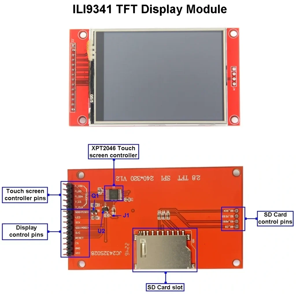
References: Reference
2. Audible Output Devices
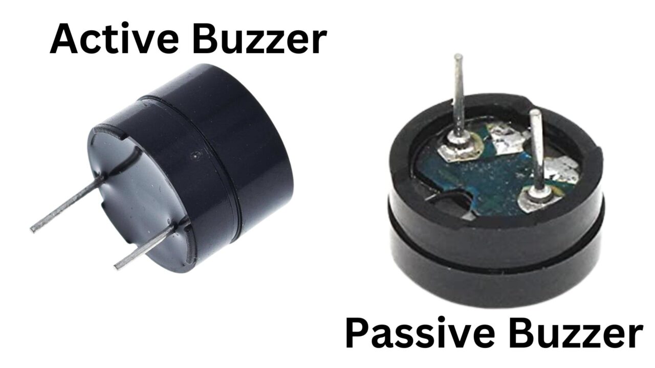
2.1 Buzzers:
Buzzers are simple sound-producing components that generate tones or alarms when powered. With Arduino, they can be controlled using digital signals to produce beeps, melodies, or alerts in projects. There are two types: active buzzers, which produce a fixed sound when powered, and passive buzzers, which require a PWM signal to generate different tones. The tone() function in Arduino helps control passive buzzers to play custom sounds. Buzzers are commonly used in alarms, timers, and notification systems. for More information
2.2 Piezoelectric Transducers:
Piezoelectric transducers convert electrical energy into mechanical vibrations, producing sound or detecting pressure changes. They work based on the piezoelectric effect, where certain materials generate voltage when stressed or vibrate when an electric signal is applied. In Arduino projects, they are used as buzzers to create beeps or as sensors to detect knocks and vibrations. A PWM signal can control the sound frequency, allowing different tones and effects. They are widely used in alarms, musical devices, and motion detection systems. for More information
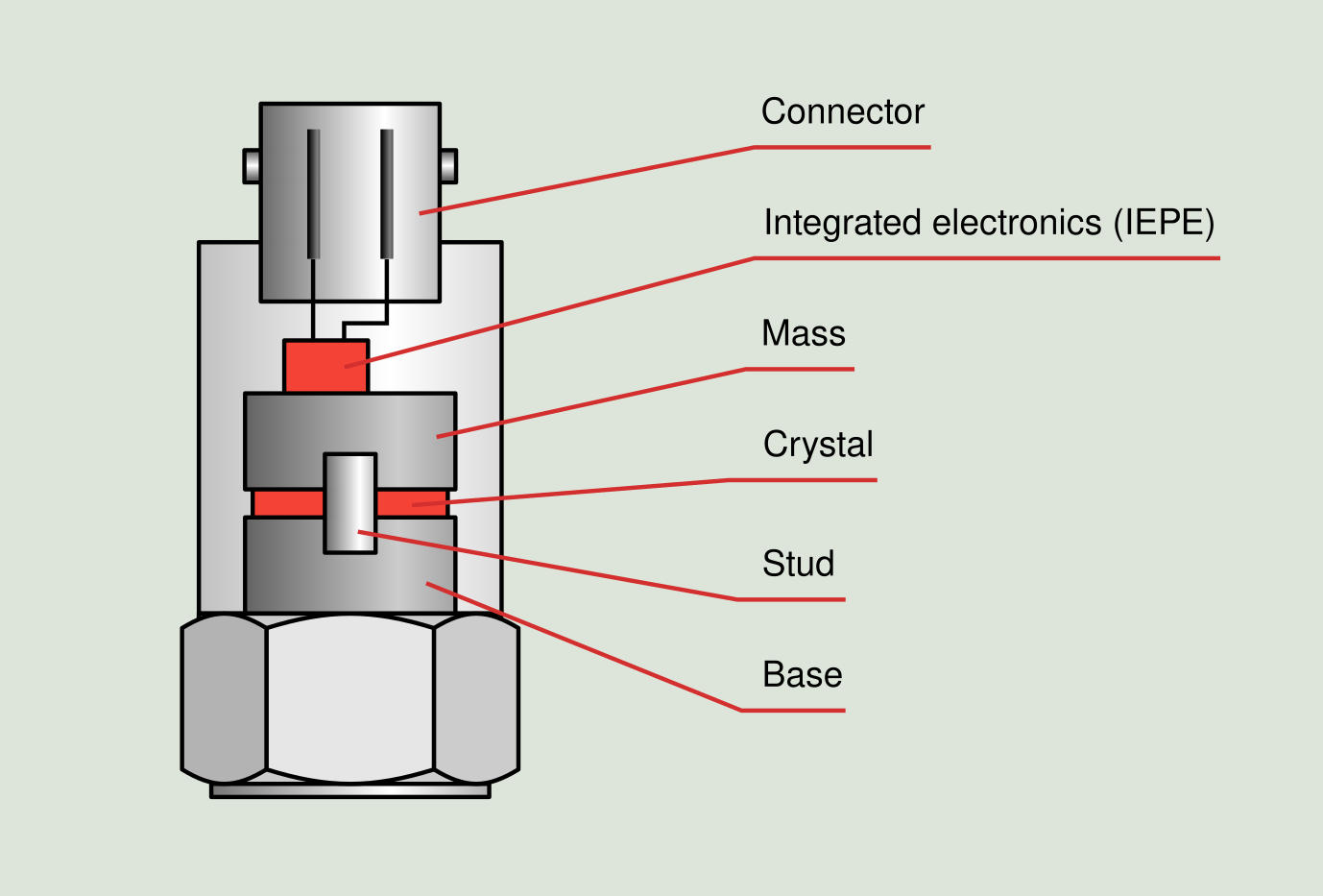
References: Reference
3. Motion Output Devices
3.1 DC Motors:
DC motors convert electrical energy into mechanical motion using electromagnetic principles. When connected to an Arduino, they require a motor driver like L298N or L293D to control speed and direction. PWM signals adjust the motor speed, while H-bridge circuits help switch the rotation direction. They are commonly used in robots, RC cars, and automation systems for movement. DC motors are simple, efficient, and widely used in various electronics and mechanical applications. for More information
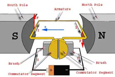
References: Reference
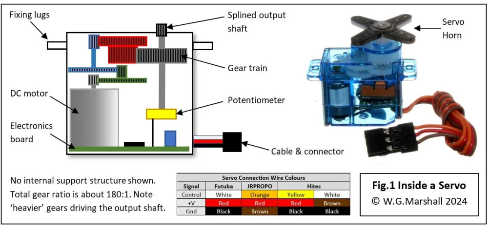
3.2 Servo Motors:
Servo motors are precise motors that rotate to a specific angle based on control signals. In Arduino projects, they are controlled using PWM signals, typically with the Servo library for easy positioning. They have three wires: power (VCC), ground (GND), and signal (PWM input) for communication. Servos are widely used in robotics, automation, and RC vehicles where precise movement is required. Unlike DC motors, they don’t spin continuously but move to a commanded position. for More information
References: Reference
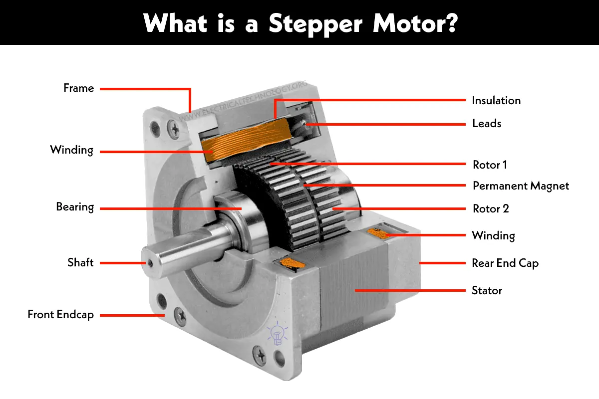
3.3 Stepper motors:
Stepper motors are precise motors that rotate in small steps rather than continuous motion, making them ideal for accurate positioning. They require a driver module like A4988 or ULN2003 to control the step sequence from an Arduino. By sending pulses to the driver, the motor moves step by step, allowing precise control over speed and direction. Stepper motors are commonly used in 3D printers, CNC machines, and robotics for controlled movement. Unlike DC motors, they do not require feedback sensors for position control. for More information
References: Reference
3.4 Solenoids:
Solenoids are electromagnetic devices that create linear motion when powered. In Arduino projects, they are controlled using a transistor or relay, as they require higher current than the Arduino can supply directly. When activated, the coil inside generates a magnetic field, pulling or pushing a metal rod. Solenoids are commonly used in door locks, valves, and mechanical automation systems. They provide quick and strong movement, making them useful for switching and actuation tasks. for More information
4. Other Specialized Output Devices
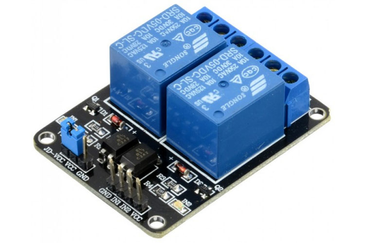
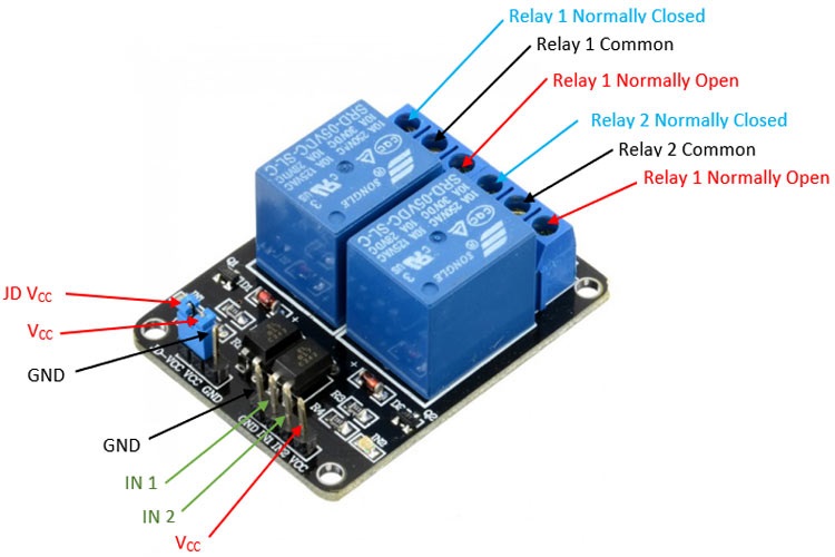
4.1 Relays:
Relaysare electrically operated switches that allow a low-power signal, like from an Arduino, to control high-power devices. They work by energizing an internal electromagnet, which moves a switch to connect or disconnect a circuit. Transistors are often used to drive relays since they require more current than an Arduino can directly provide. Relays are commonly used in home automation, motor control, and industrial applications. They help safely control high-voltage devices like lights, fans, and appliances with a low-voltage microcontroller. for More information
|
|
How Output Devices Work
Output devices receive signals from a microcontroller or processor, typically in the form of digital or analog signals:
1. Digital Output: The microcontroller sends a HIGH (1) or LOW (0) signal to control the device. Example: Turning an LED ON/OFF.
2. Analog Output (PWM - Pulse Width Modulation): A method of simulating an analog signal using a digital pin by varying the pulse duration. Example: Controlling motor speed or LED brightness.
Some devices, like displays and stepper motors, require communication protocols such as:
I2C (Inter-Integrated Circuit): Used for sensors and displays.
SPI (Serial Peripheral Interface): Used for high-speed data transfer (e.g., TFT displays).
UART (Universal Asynchronous Receiver-Transmitter): Used for serial communication with external modules.
Group Assignment
Objective of the Group Assignment
- Measure the power consumption of an output device
The output devices for which we measured the power consumption are:
- DC motor
- OLE Display
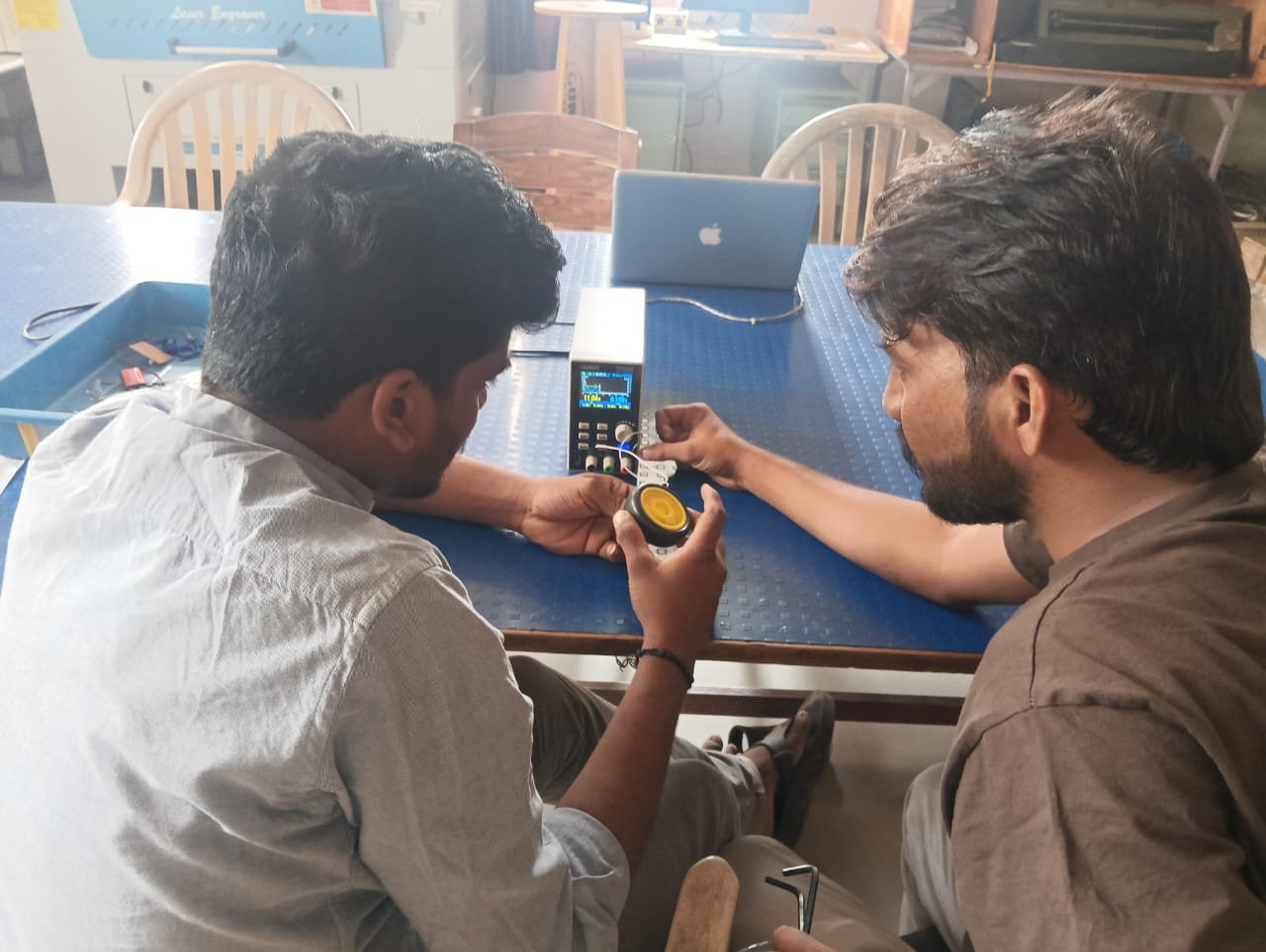
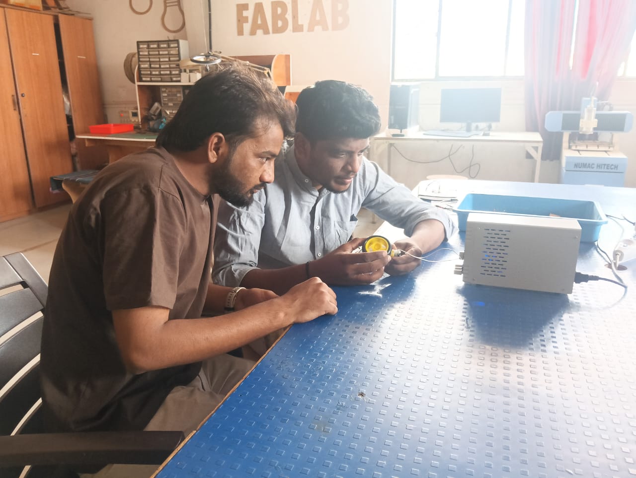
1. We connected the DC motor to the owon power supply and first tested it with 5V and 1A current. The results are shown below.
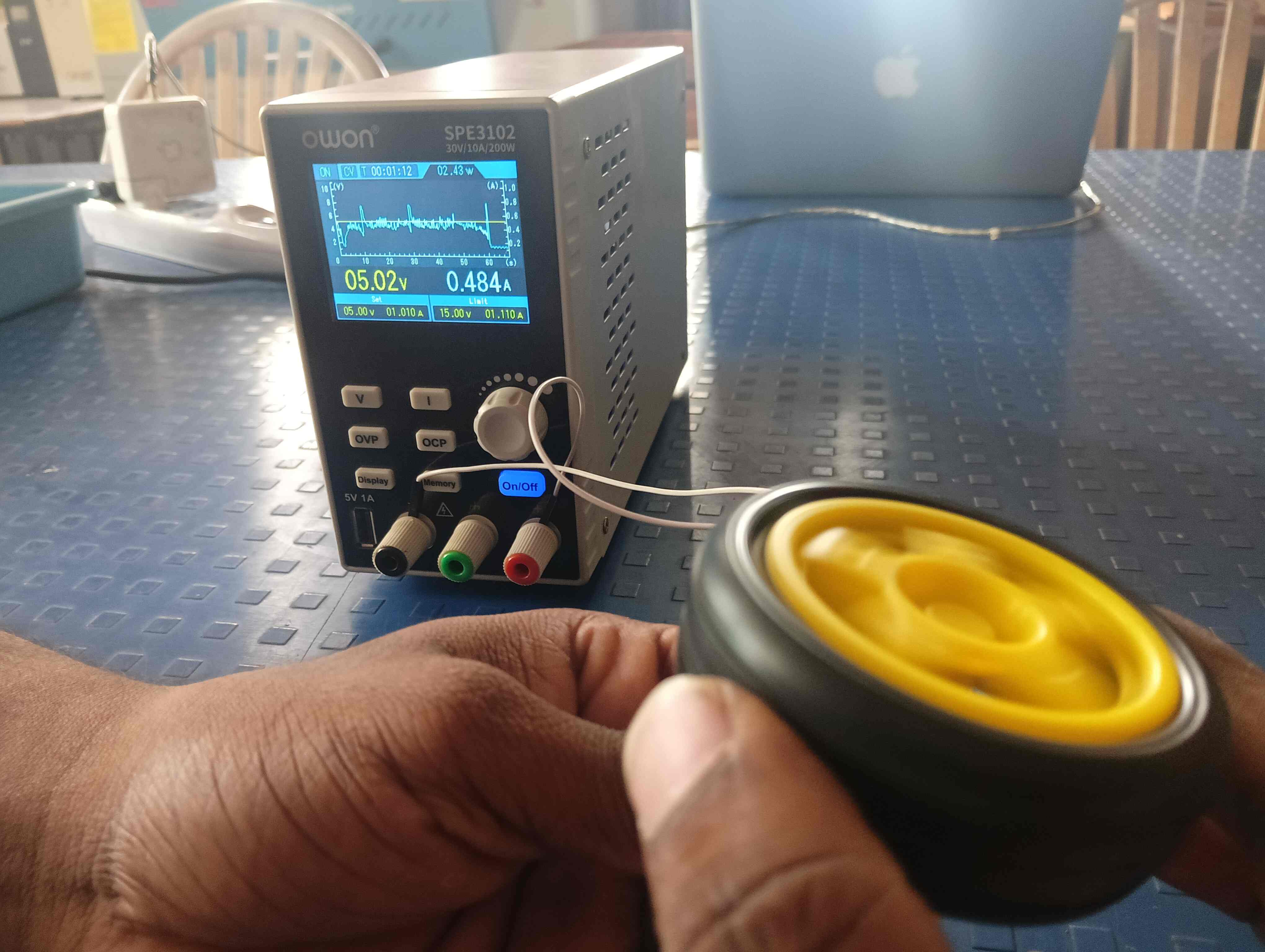
Collaborating with the team to measure power consumption efficiently. Analyzing data to optimize energy usage and improve performance.
|
|
We applied a load to the DC motor, and it drew a current of 0.5A. This shows how the motor's current consumption changes under load. The results indicate the motor's efficiency and power usage when operating with load.
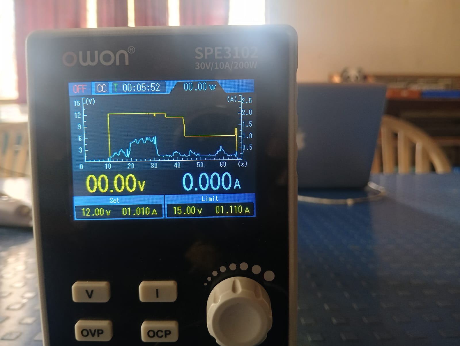
After completing the previous test, we increased the voltage to 12V. The current drawn by the DC motor was measured, and the results are shown below. This test helps observe how the motor behaves with higher voltage input.
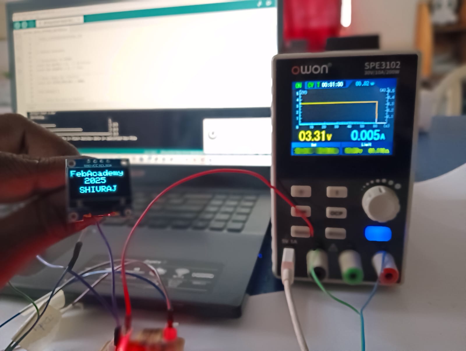
2. After completing the DC motor test, we tested the OLED display to measure its power consumption. We applied 3.3V and 0.5A to the display. The results showed how much power the OLED display consumes under these conditions.

|
|
Discussing how much power the OLED display consumes.
Individual Assignment
Objective of the Individual Assignment:
-Connect an output device to the custom microcontroller board you designed.
- Write and upload a program to control the output device and perform a specific task.
1. Designing a board for output devices
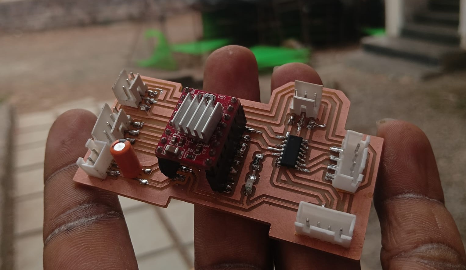
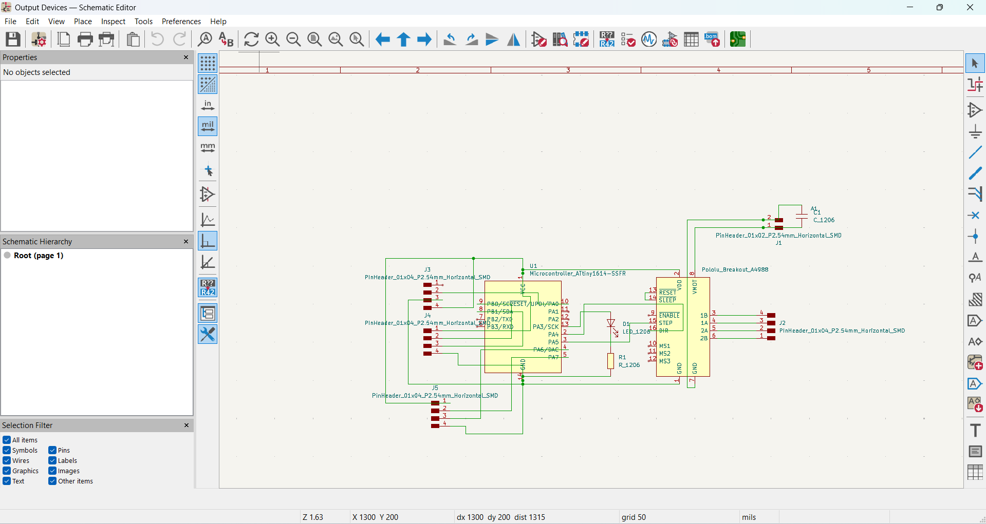
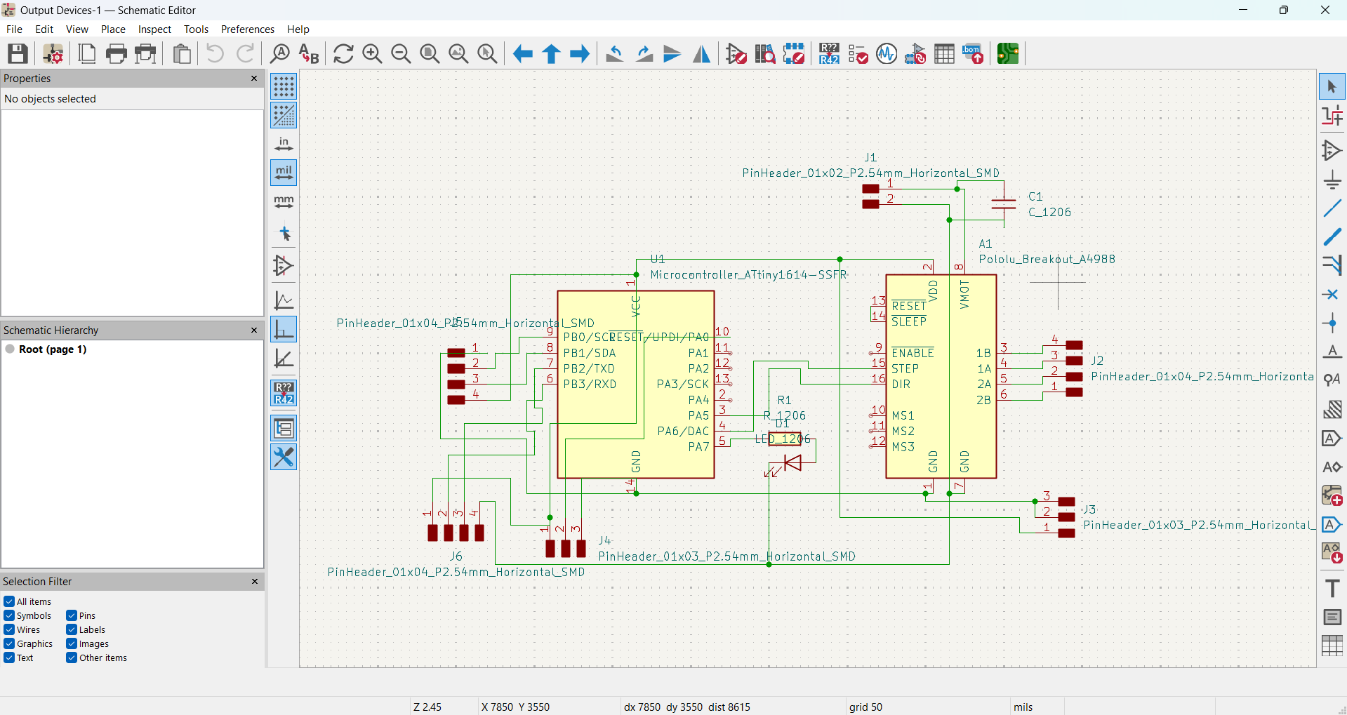
For this week’s assignment, I designed a PCB for output devices, following a similar approach to previous weeks. I carefully planned the circuit to ensure it supported the specific output components I intended to use. After finalizing the design, I proceeded with milling, soldering, and testing the board to verify its functionality.
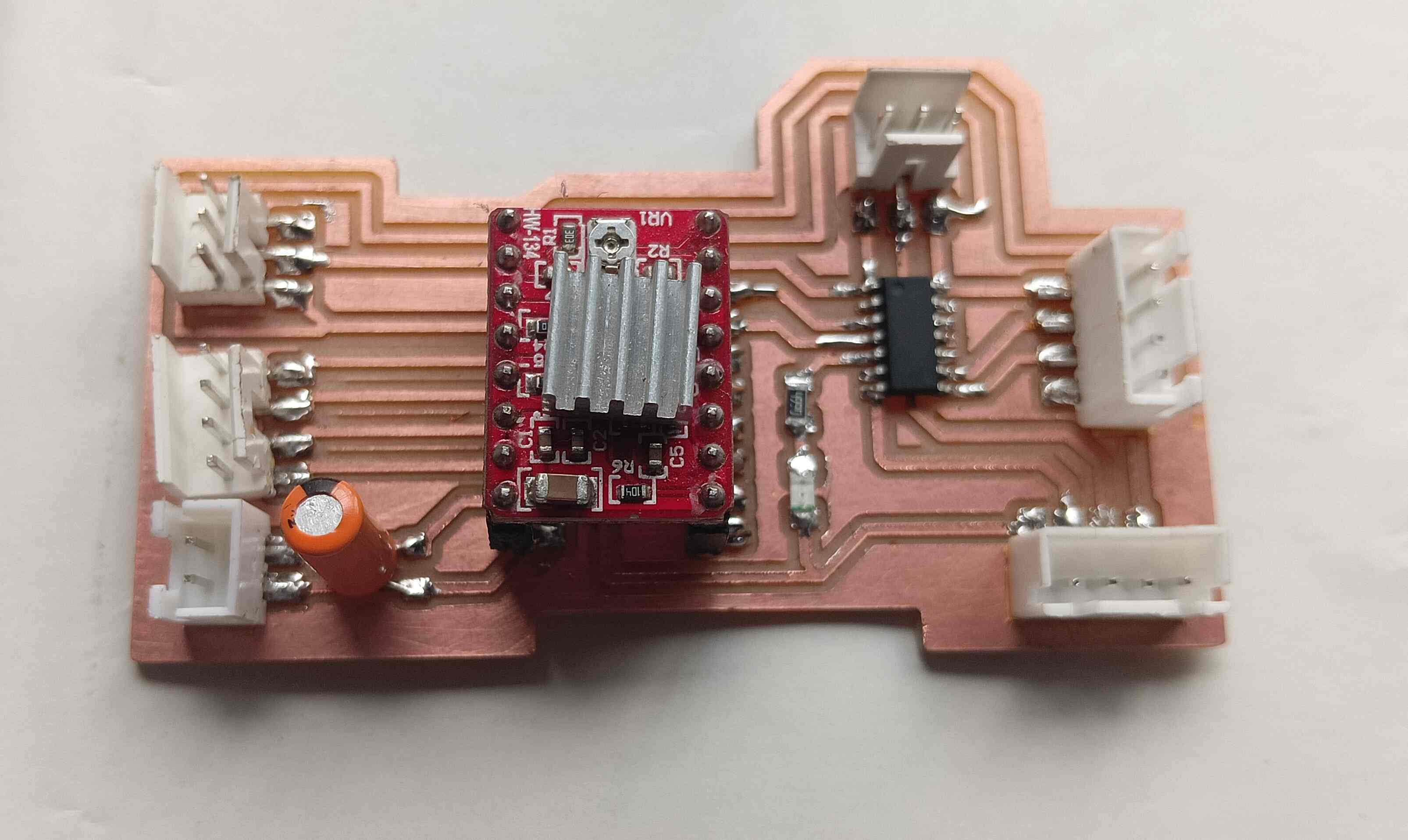
In this assignment, I worked with a stepper motor, relay, and DC motor. The stepper motor was used for precise movement control, requiring a driver module like A4988 to receive step signals from the microcontroller. The relay acted as a switch, allowing the microcontroller to control high-power devices, and I integrated a transistor circuit to operate it safely. For the DC motor, I used a motor driver such as L298N to control its speed and direction, utilizing PWM signals for smooth adjustments. Each of these components was integrated into my PCB, and I programmed the board to test and ensure their proper operation.
For this week’s assignment, I started designing a PCB for output devices, just like in previous weeks. I planned the circuit to support the specific output components I wanted to use. After designing, I proceeded with milling, soldering, and testing the board.
|
|
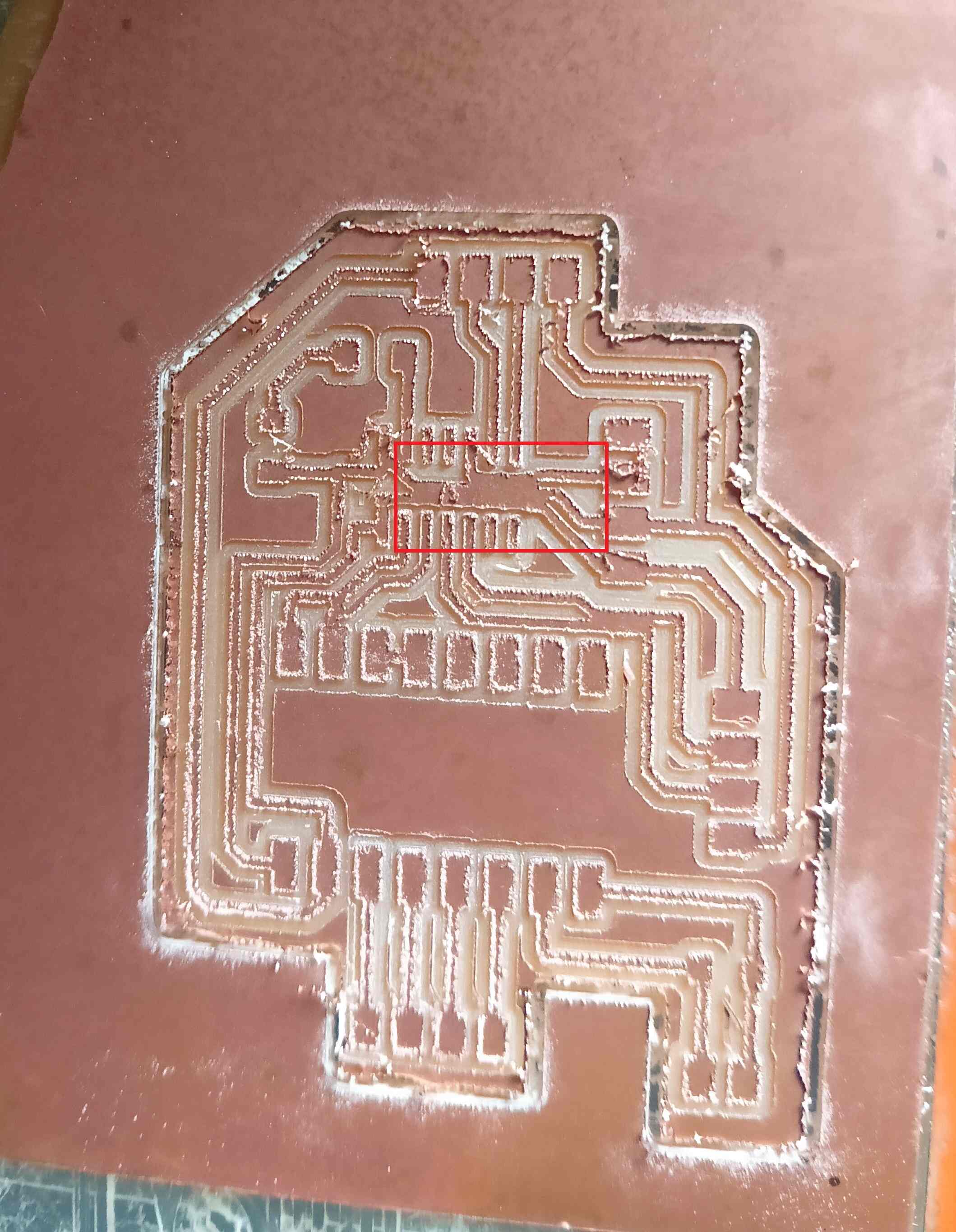
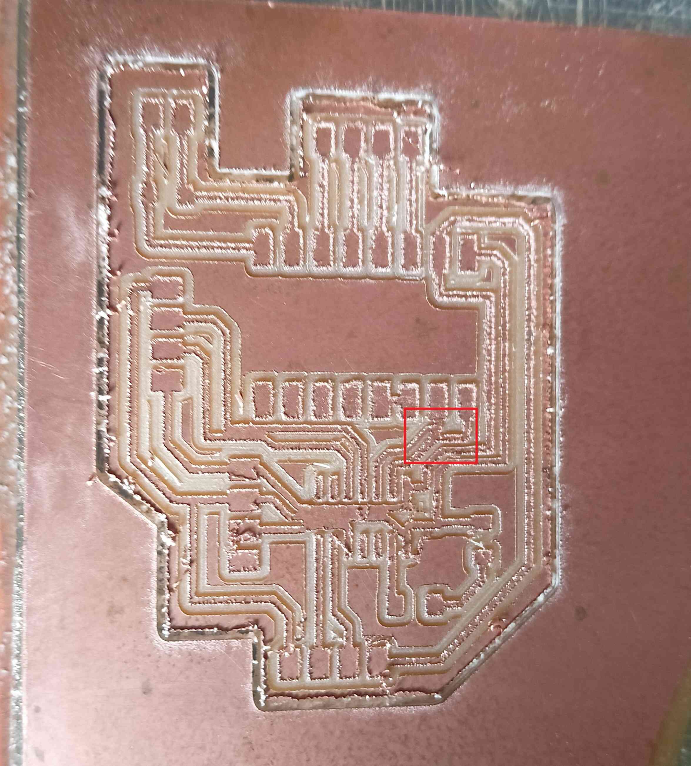
I faced an issue with my board after milling my PCB, as the traces got mixed up with each other. Below, I have shown the image of the problem.
|
|
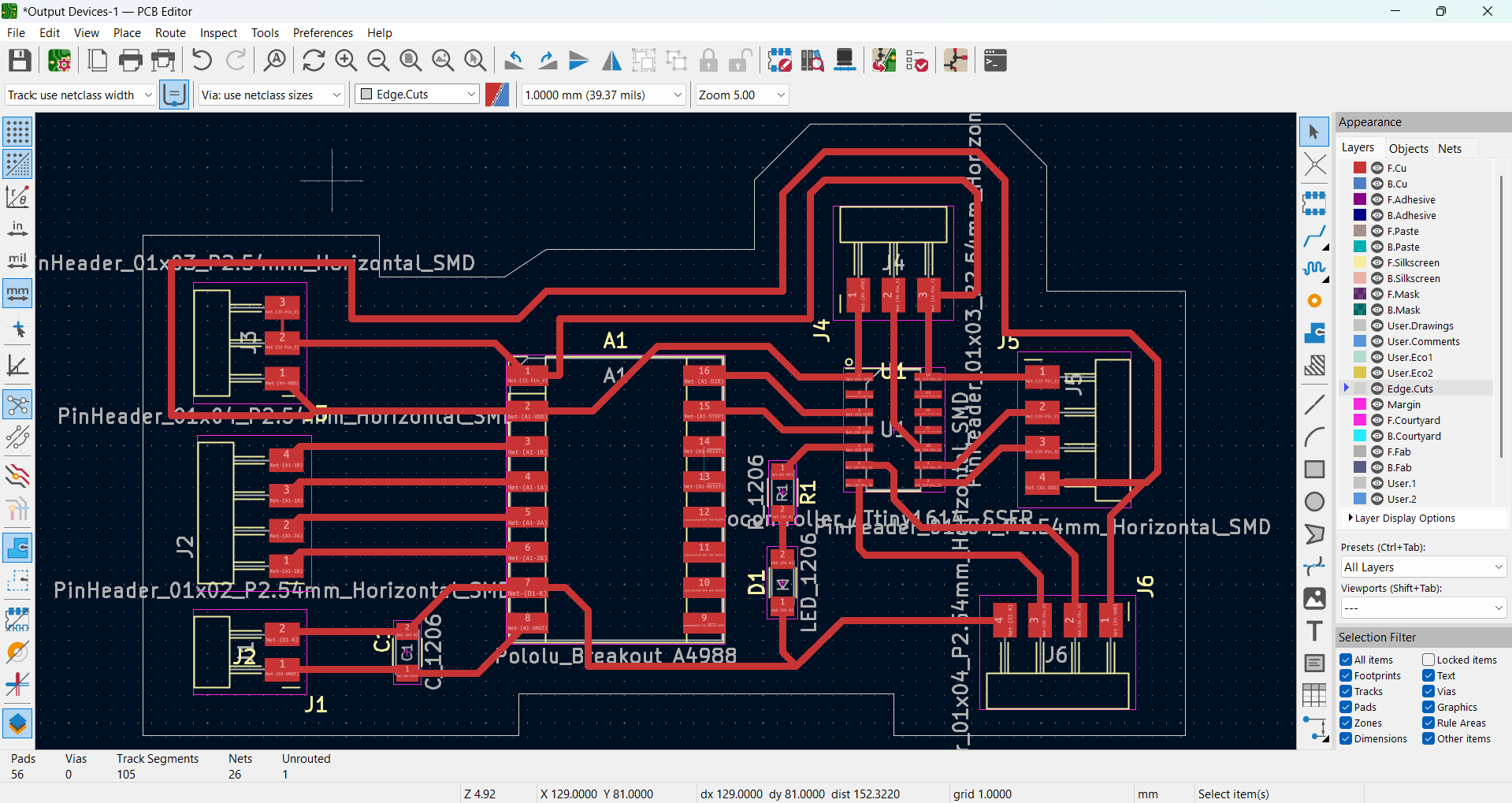
After realizing my mistake, I have decided to start a fresh design. This time, I will focus on maintaining sufficient spacing between the traces to ensure proper functionality and avoid short circuits. By carefully redesigning the layout, I aim to improve both efficiency and reliability. Taking a more precise approach will help me create a better and more effective circuit.
|
|
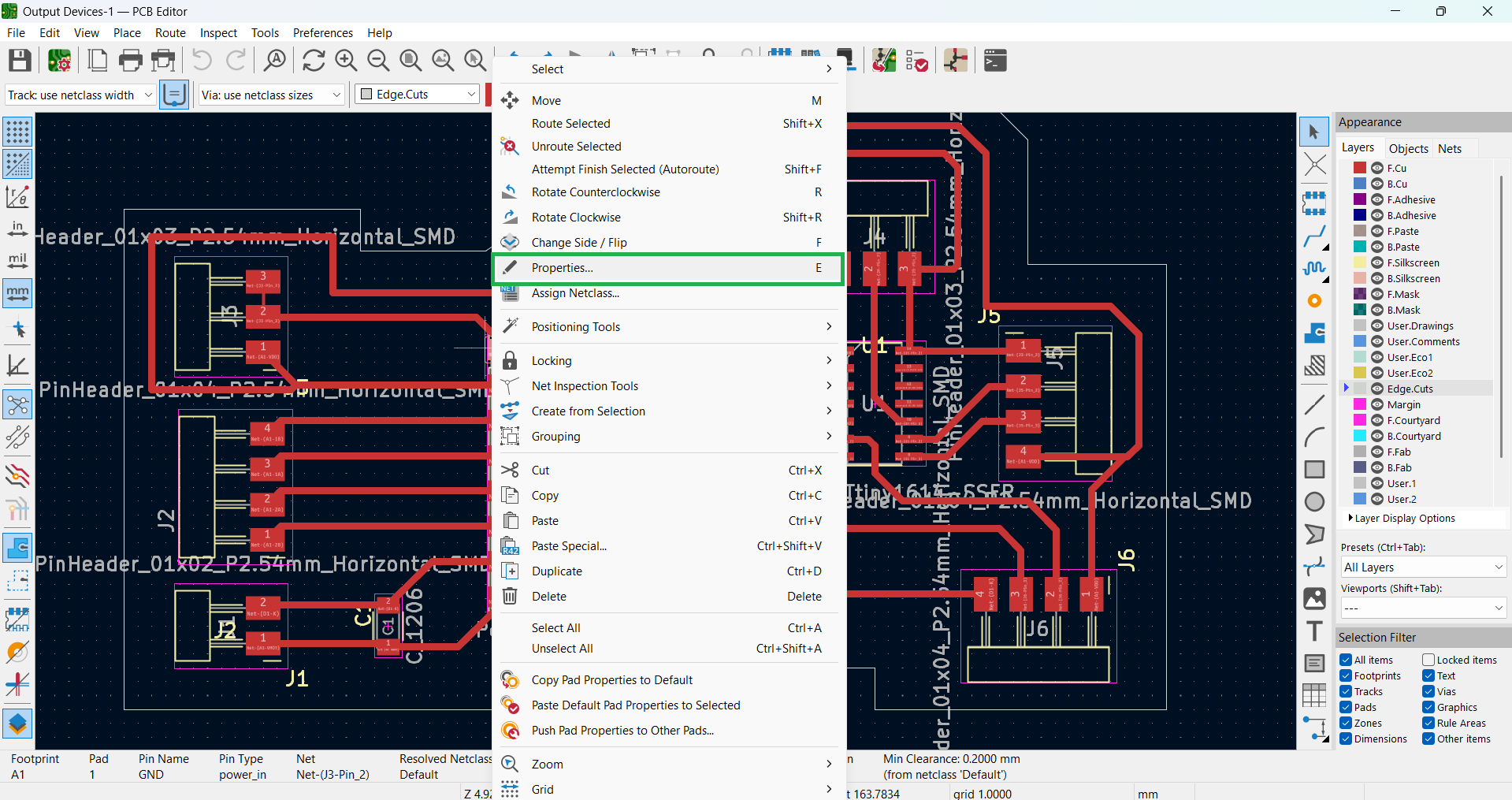
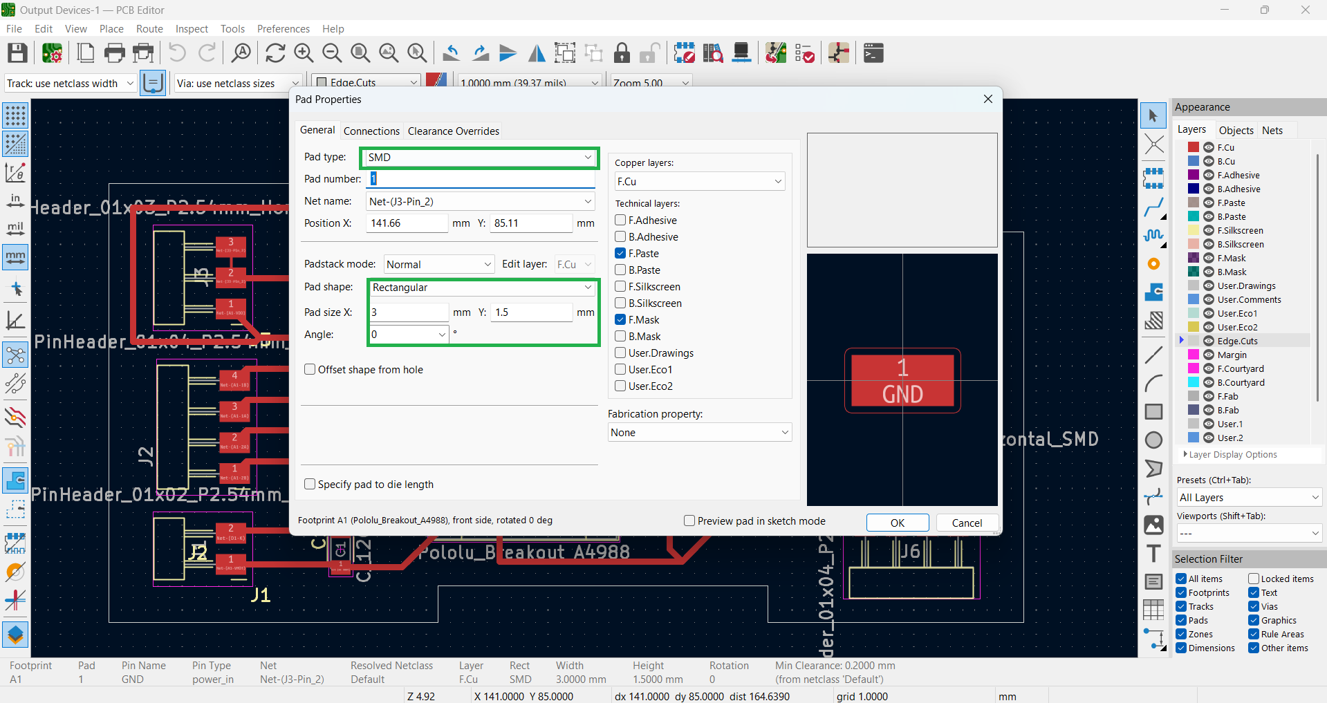
Below, I demonstrate how I modified the motor driver holes in the SMD design.
|
|
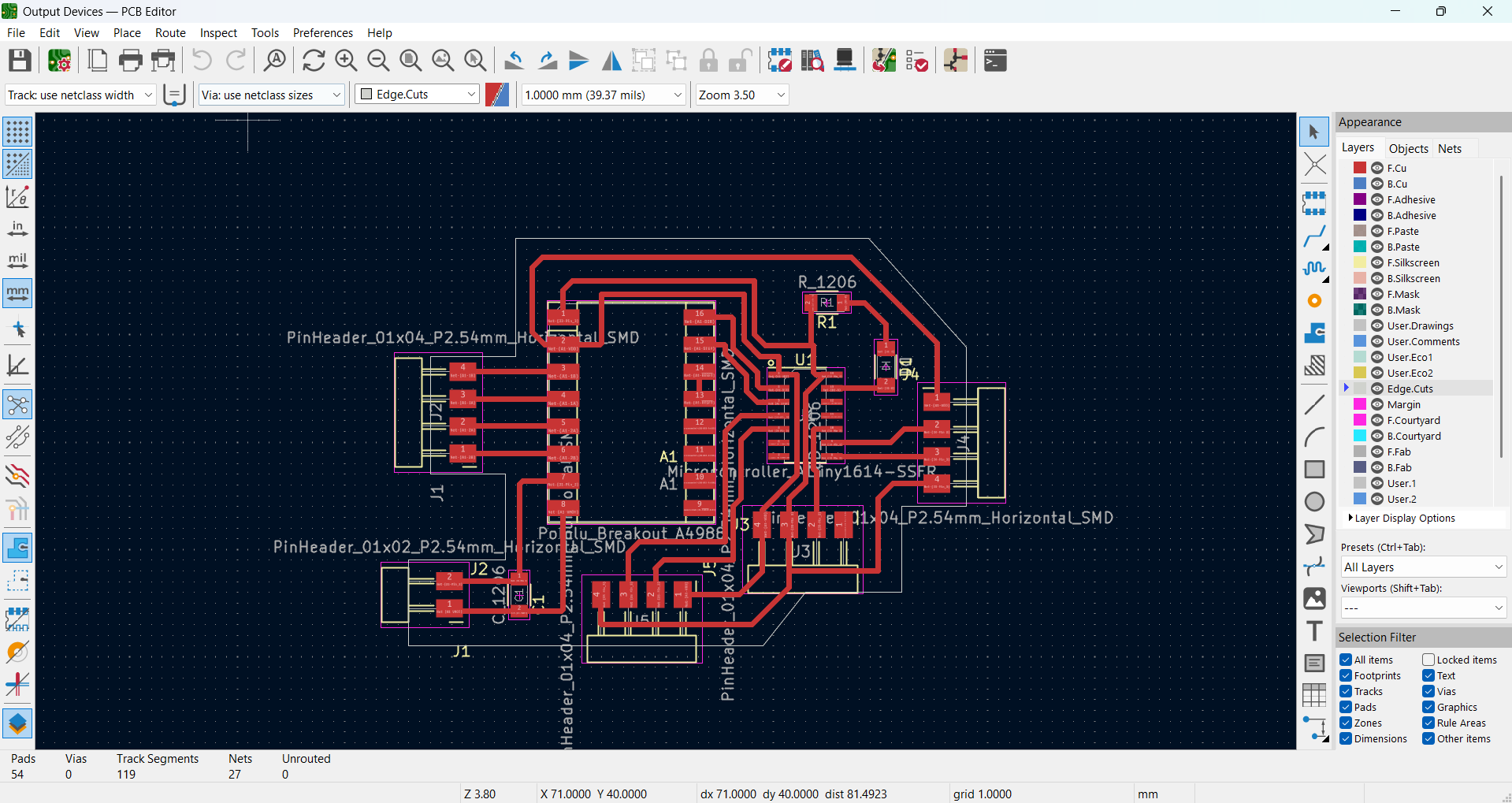
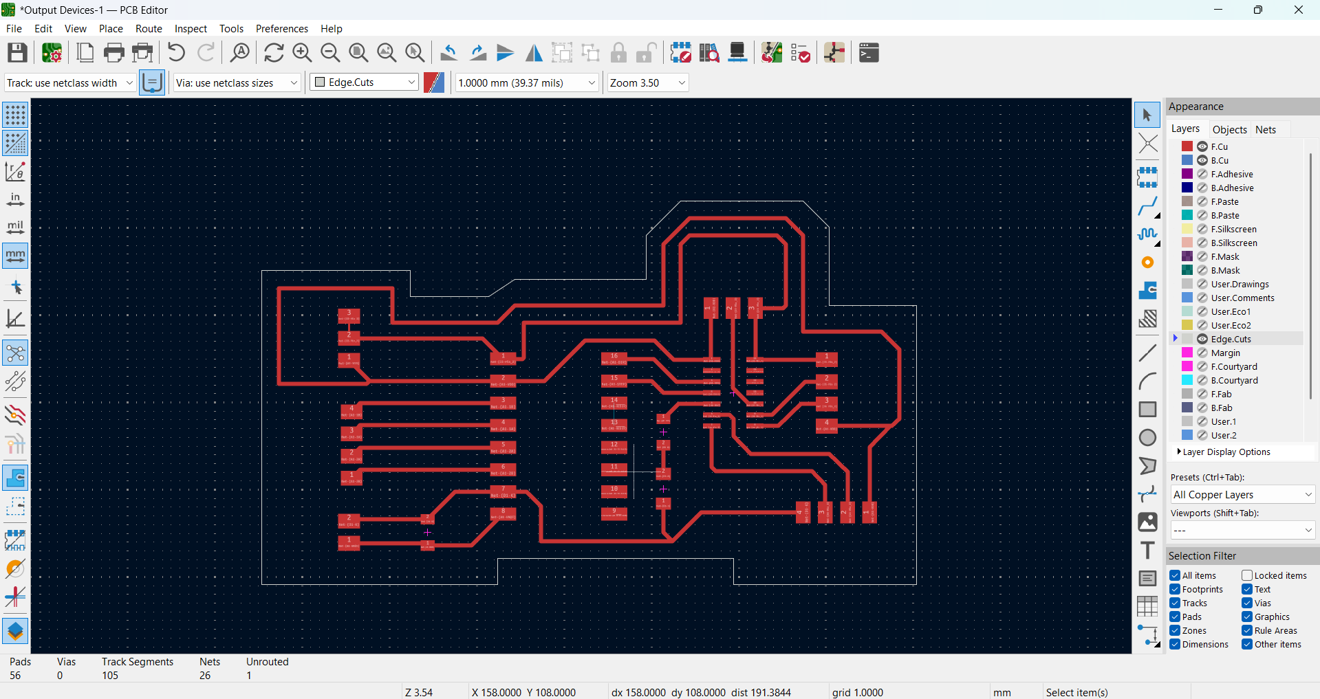
After completing the design, all copper layers are displayed below, along with the edge cuts for proper board outlining.
|
|
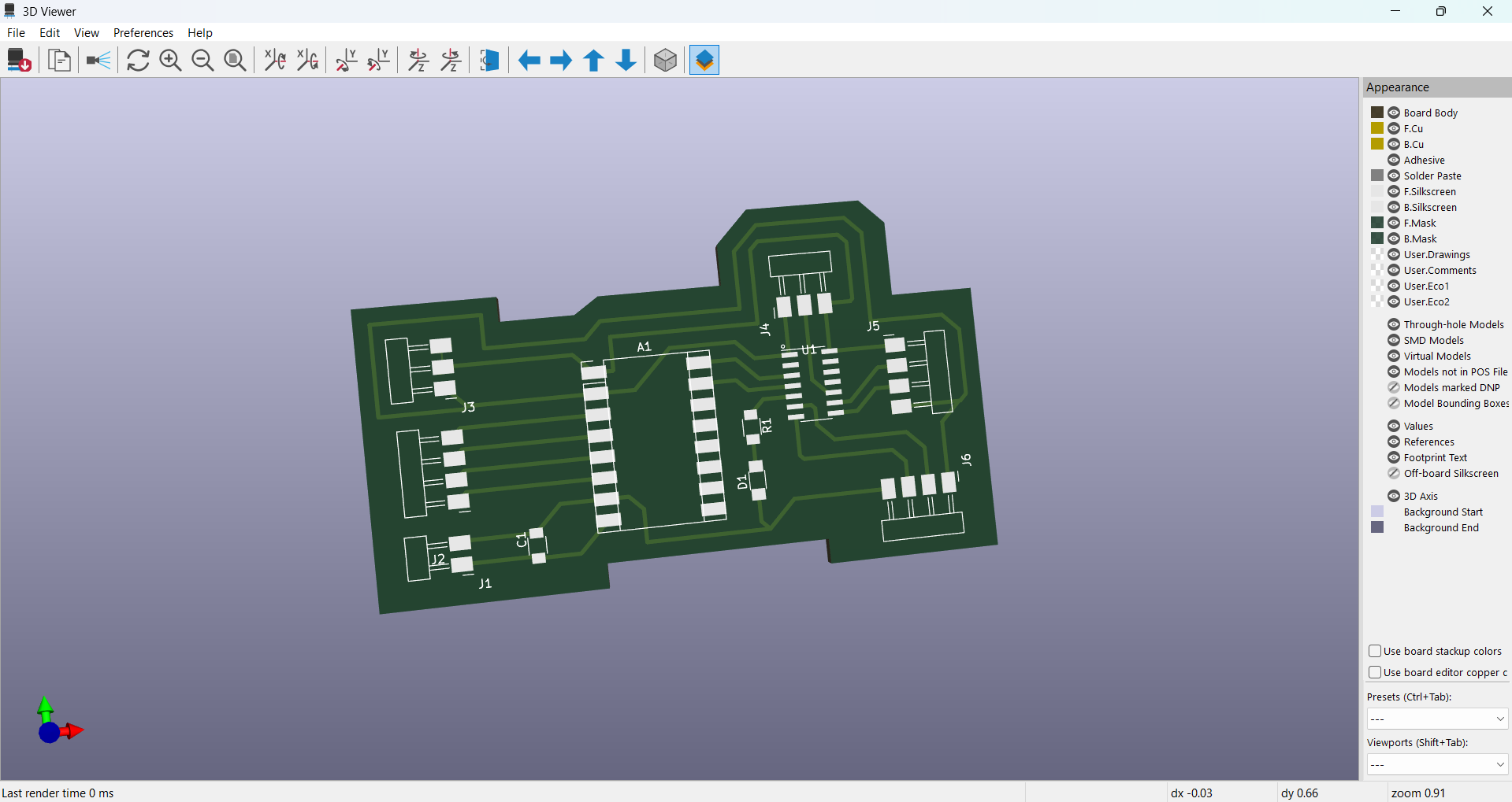
3D view of my design
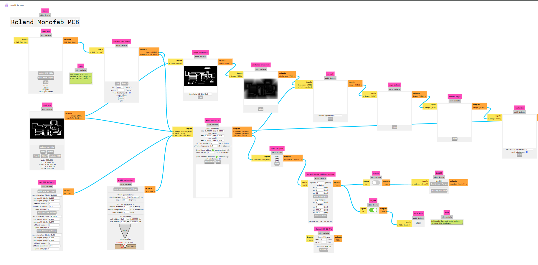
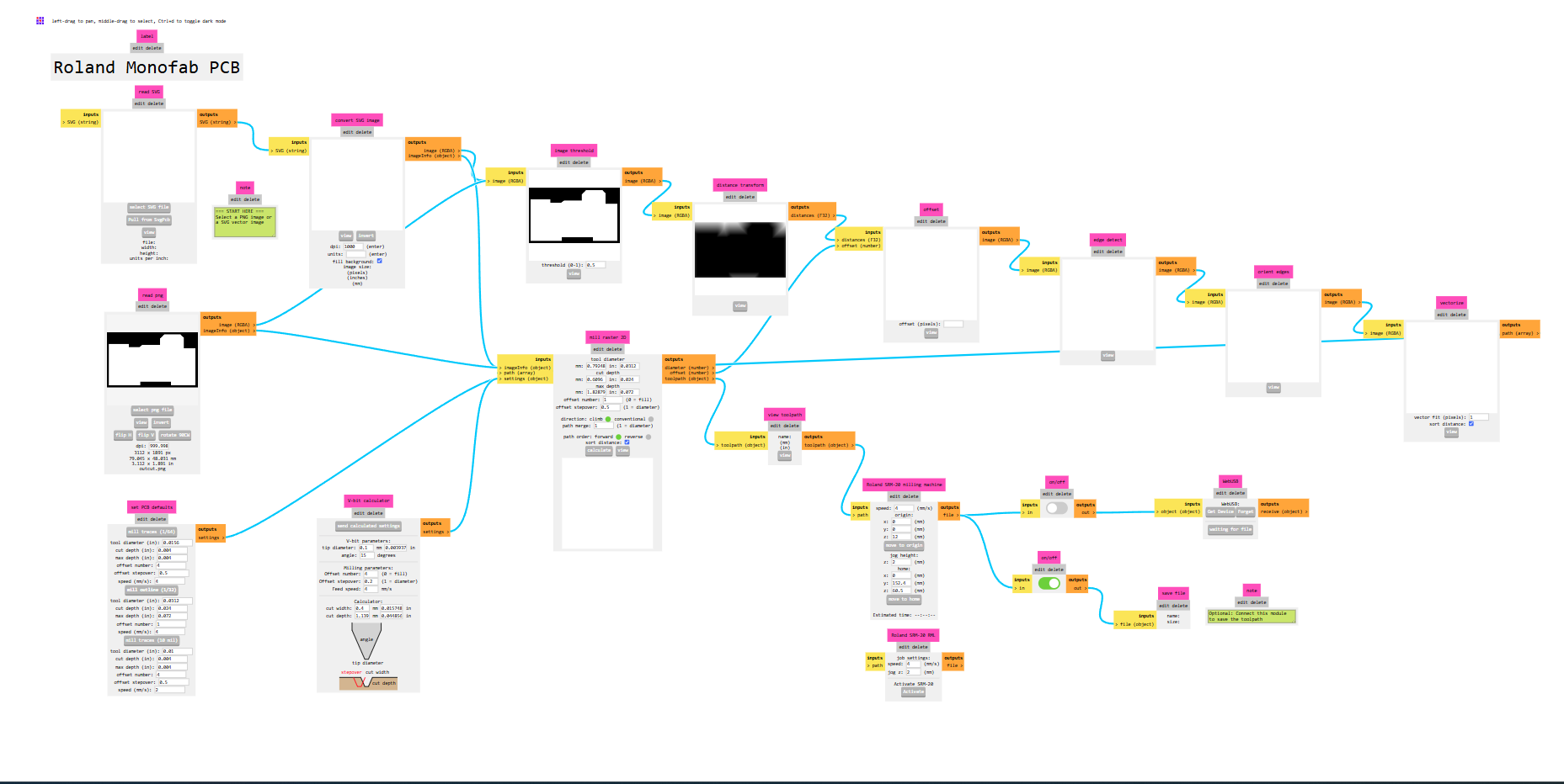
I am using Mods CE to convert my PNG image to PCB format with custom settings.
|
|
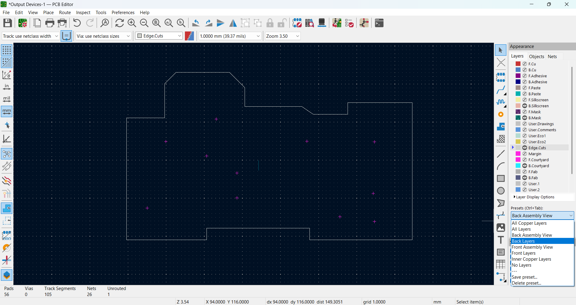
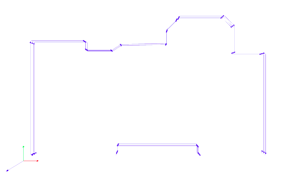
Below is the edge cut of my PCB.
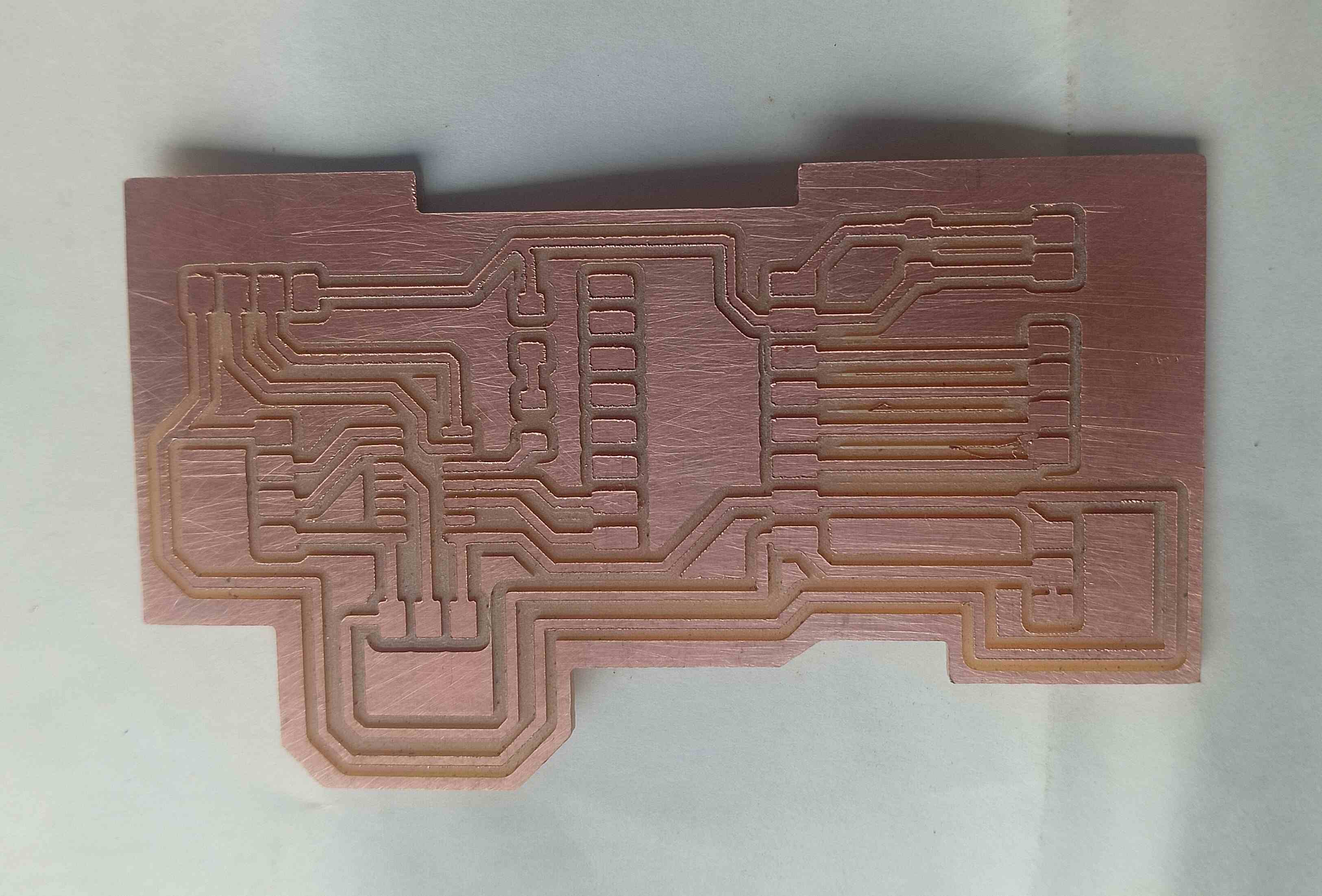
After completing the milling of my PCB, the output is shown below.
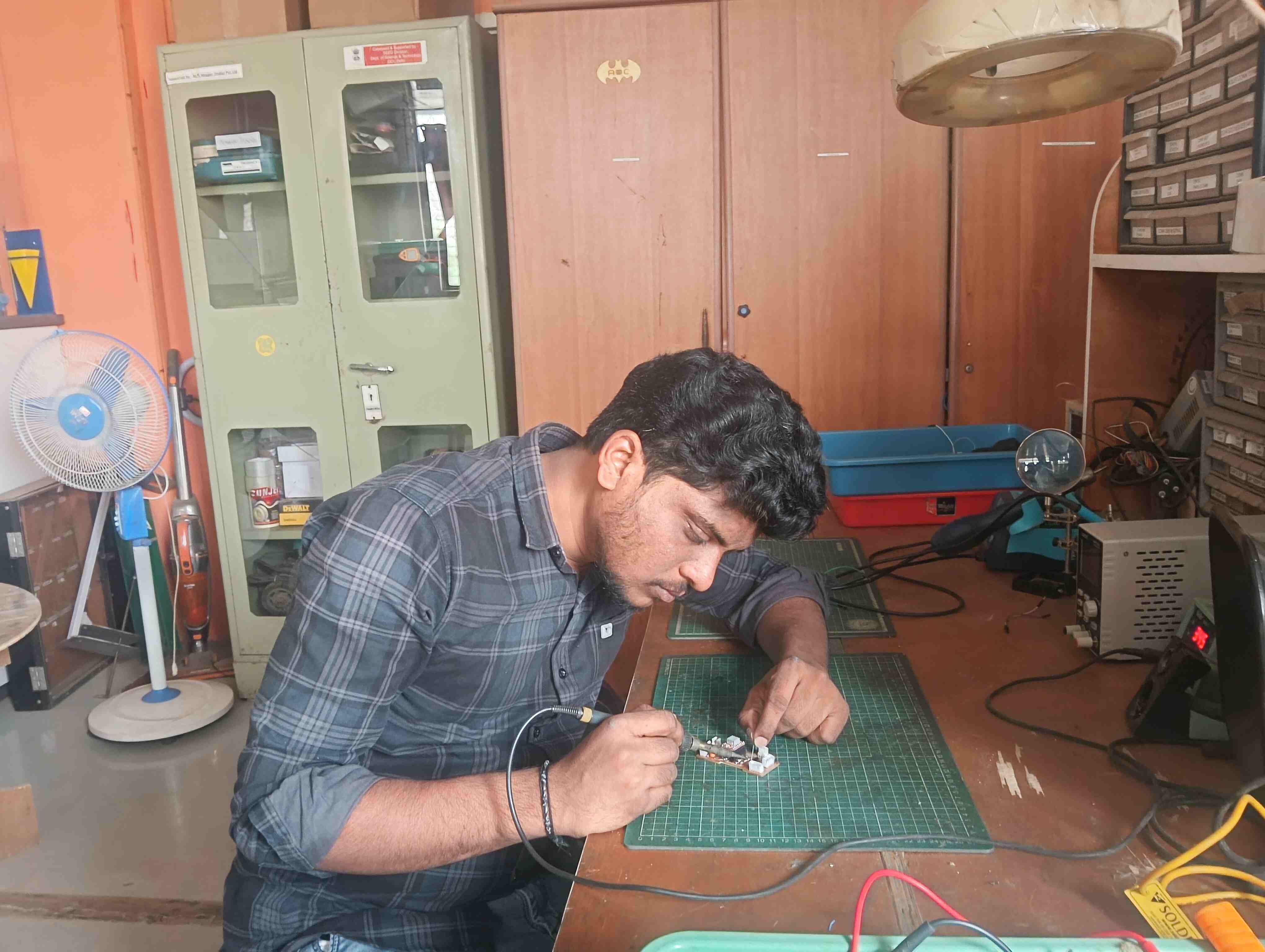
I checked all the tracks before starting the soldering process. After ensuring everything was correct, I began soldering carefully. This helped me avoid any connection issues.
|
|
|
After completing the soldering, I started coding for this week's assignment. I used the ATtiny1614 microcontroller for my project.
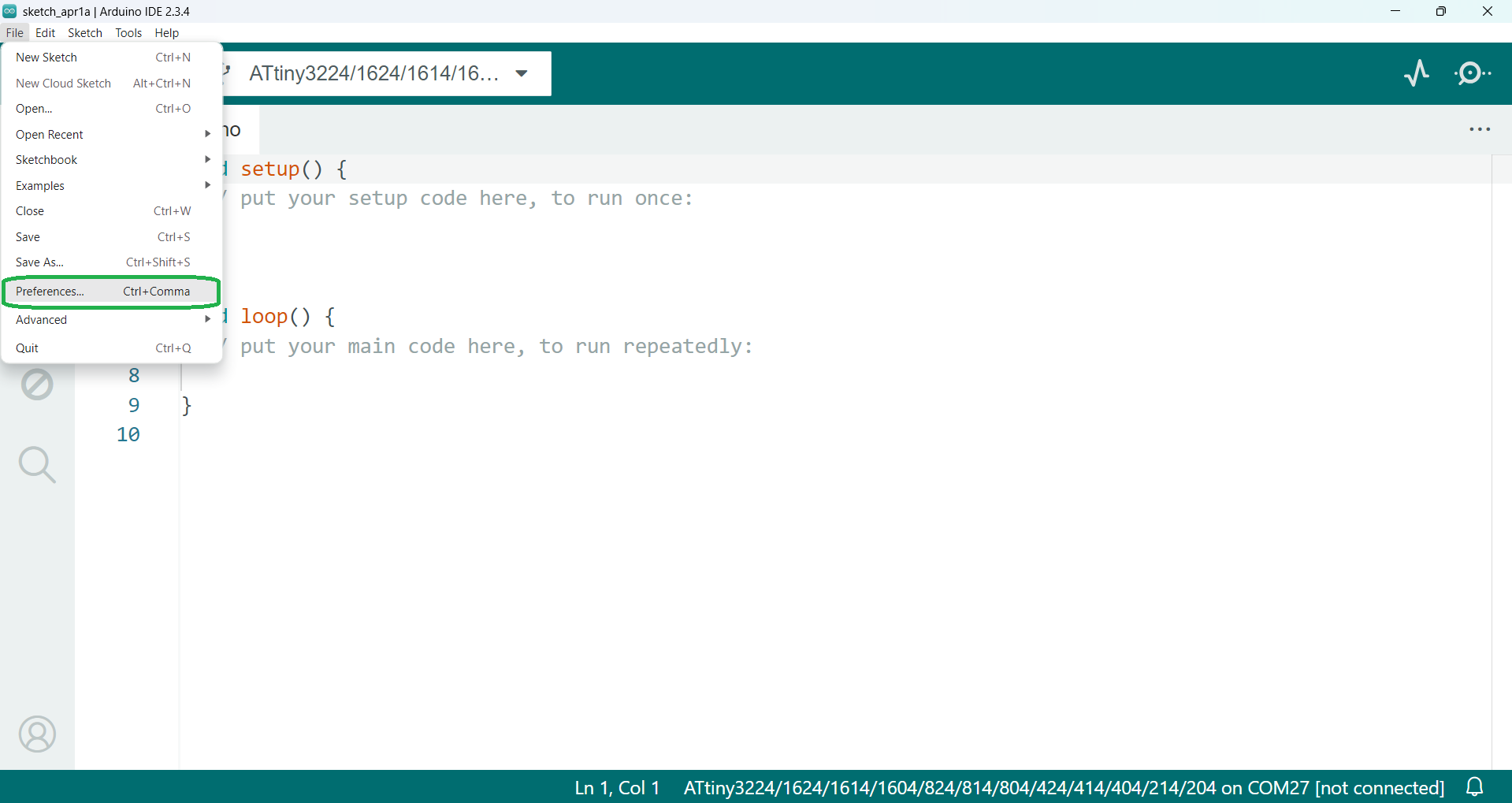
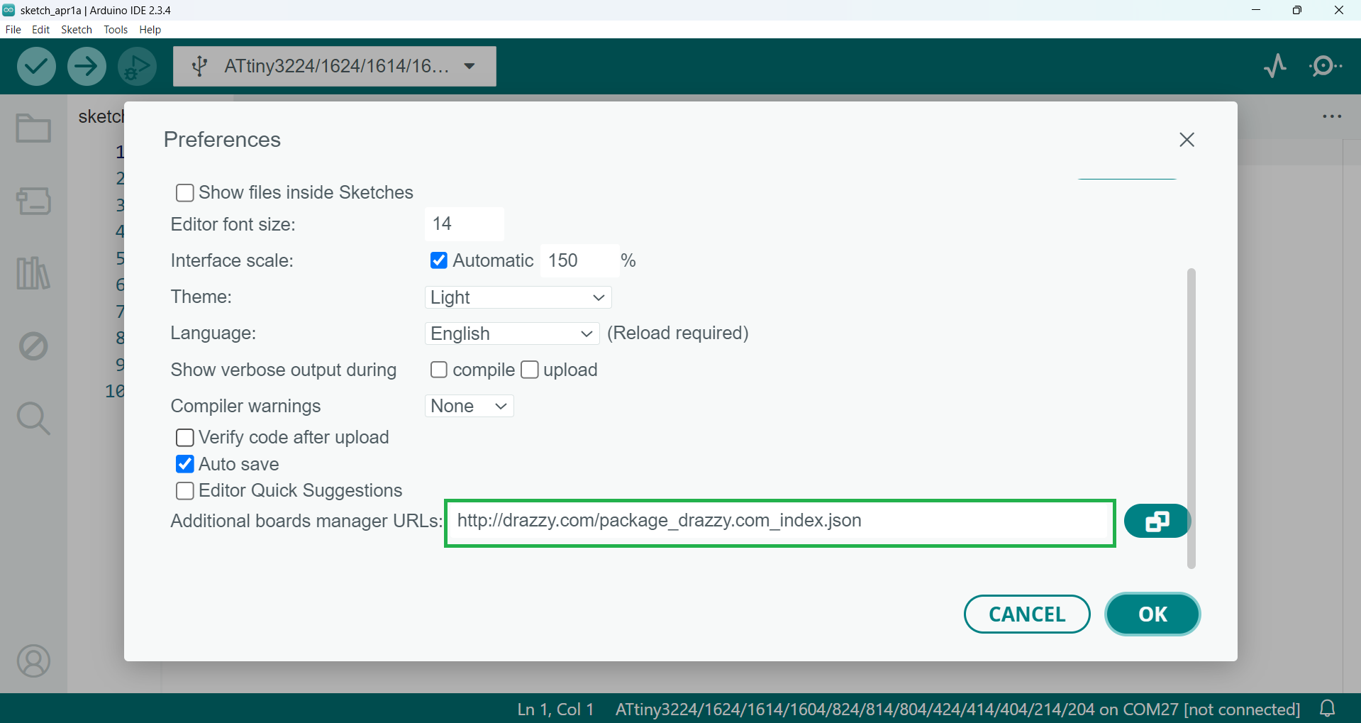
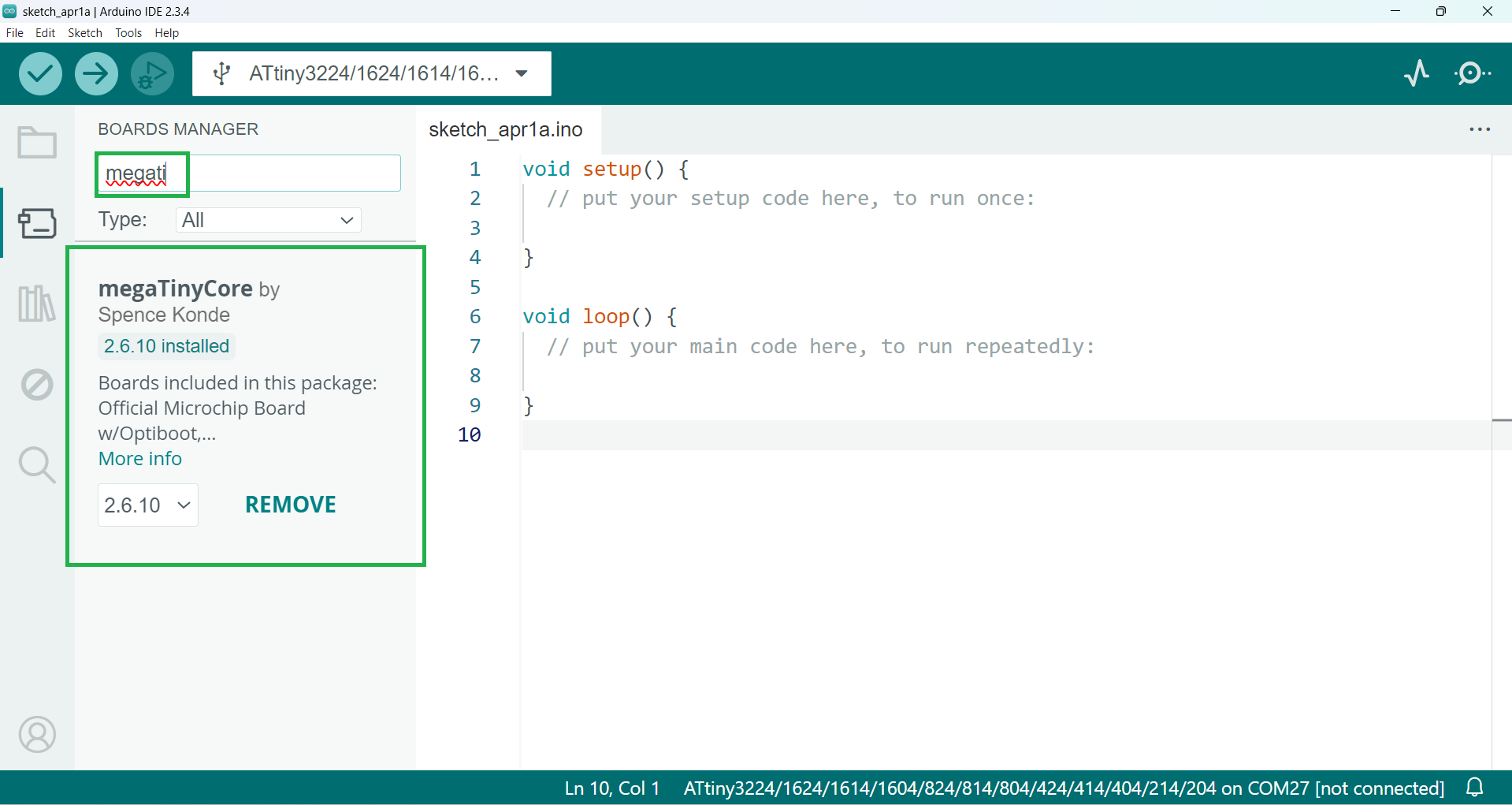
Before programming my board, I added the ATtiny boards to the Arduino IDE by installing the necessary board definitions and drivers. The steps are shown below; once the ATtiny boards were included, I successfully uploaded the code to my board.
|
|

|
|
ATtiny1614 microcontroller
The ATtiny1614 is a low-power 8-bit microcontroller from Microchip’s tinyAVR® family. It features a 16MHz internal oscillator, 16KB of flash memory, 2KB of SRAM, and 256 bytes of EEPROM. This microcontroller supports UPDI (Unified Program and Debug Interface) for programming and debugging, making it easy to work with. It has multiple I/O pins, UART, SPI, and I2C communication interfaces, making it suitable for embedded systems. The ATtiny1614 is commonly used in compact projects due to its small size, efficiency, and versatility.
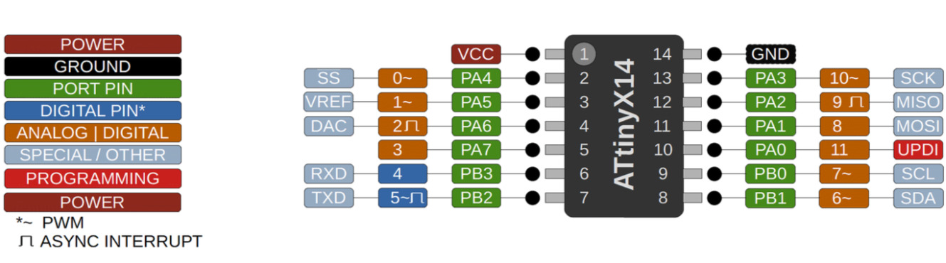
References: Reference
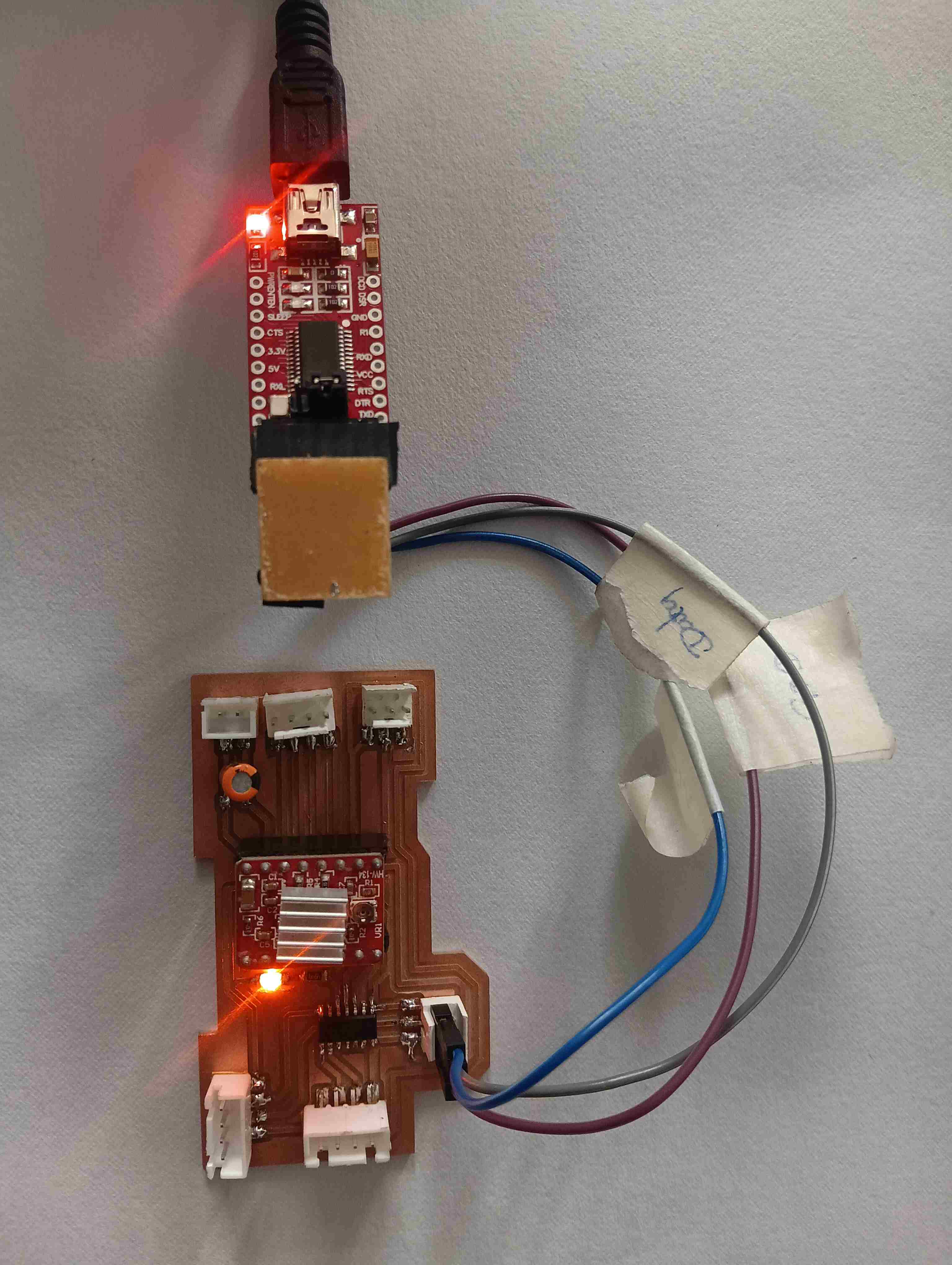
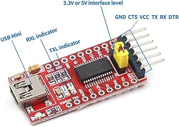
For uploading the program to the Arduino, I used the HW-417-V1.2 TTL converter. I connected my board to the TTL converter as follows: TX pin to RX pin, RX pin to TX pin, VCC to VCC, and GND to GND. When I first tried to upload the program, I encountered an issue with the upload process. I then started searching for the cause of the error to find a solution.
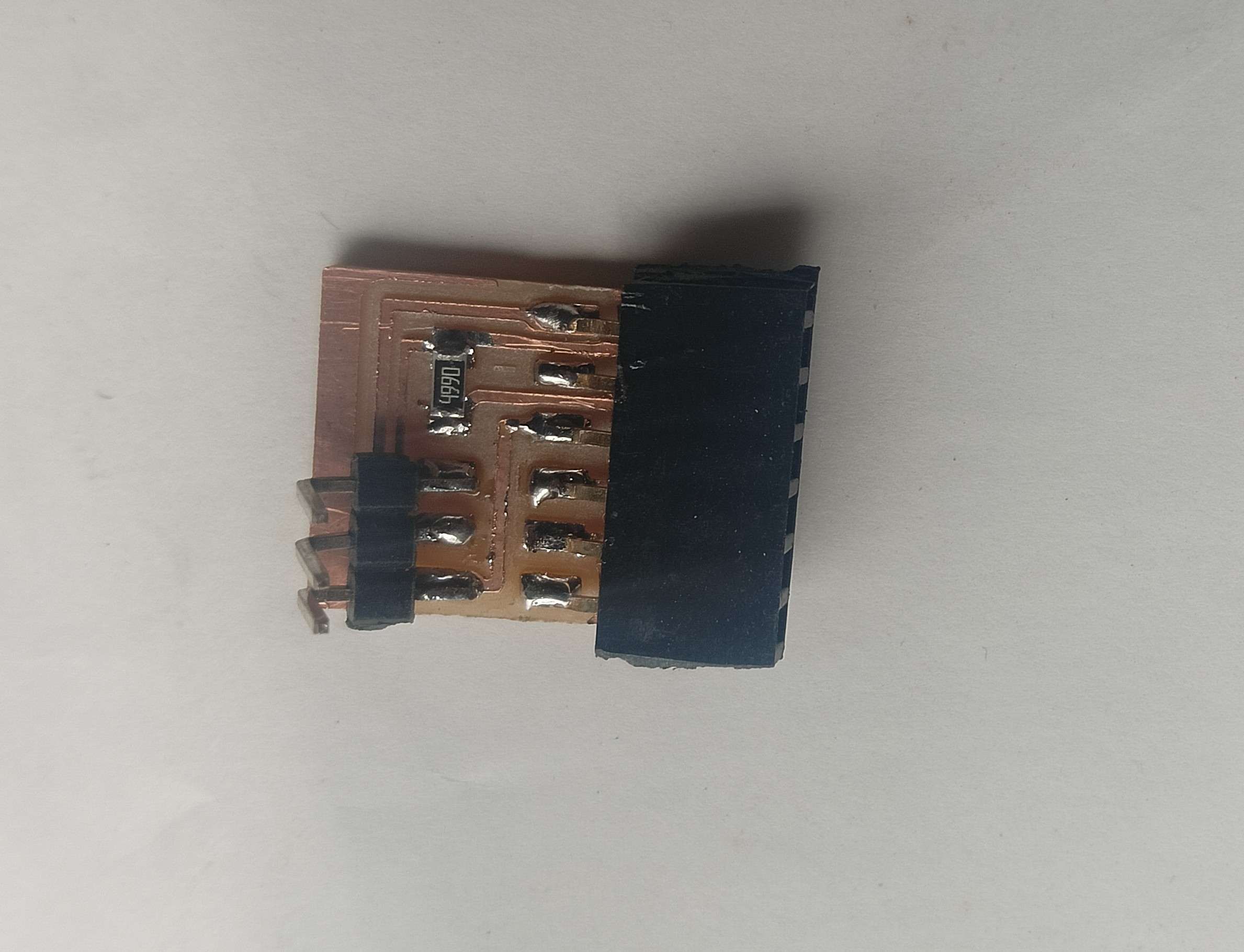
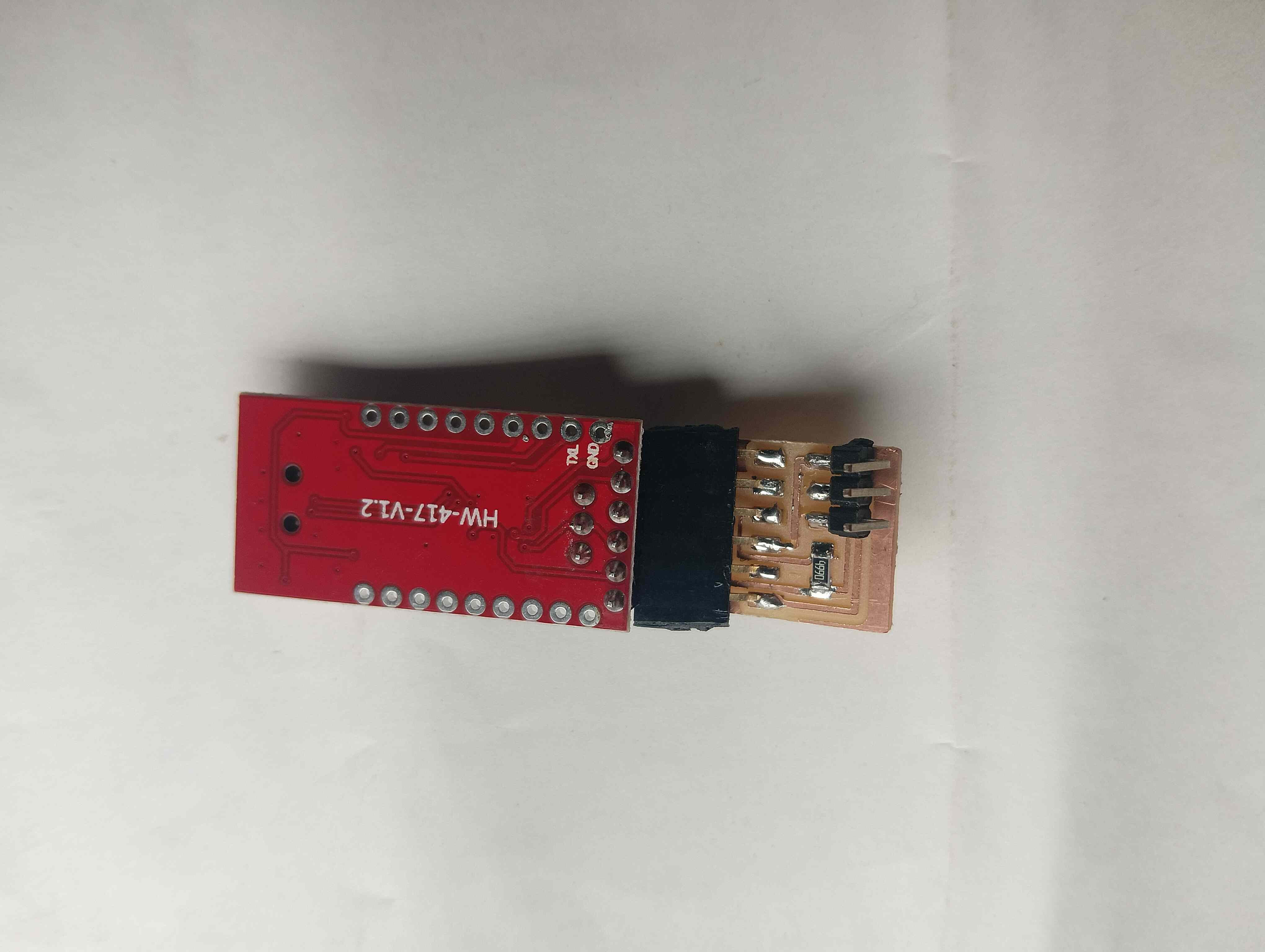
After some time searching, I found a solution for the issue. In the Fab Academy Embedded Programming schedule, under hardware resources, I found a board for Serial UPDI3. I took that board from the available resources and used it for programming. Using that design, I made a small PCB to improve the uploading process. Below, I am providing the details of how I used it for programming and uploading.
resources: resources#1, resources#2, resources#3, resources#4
|
|
Now, my program runs smoothly, and the program was uploaded successfully. I started with the blink code to check if my board was working properly. This initial test helped ensure everything was functioning as expected. Once confirmed, I proceeded with further programming.
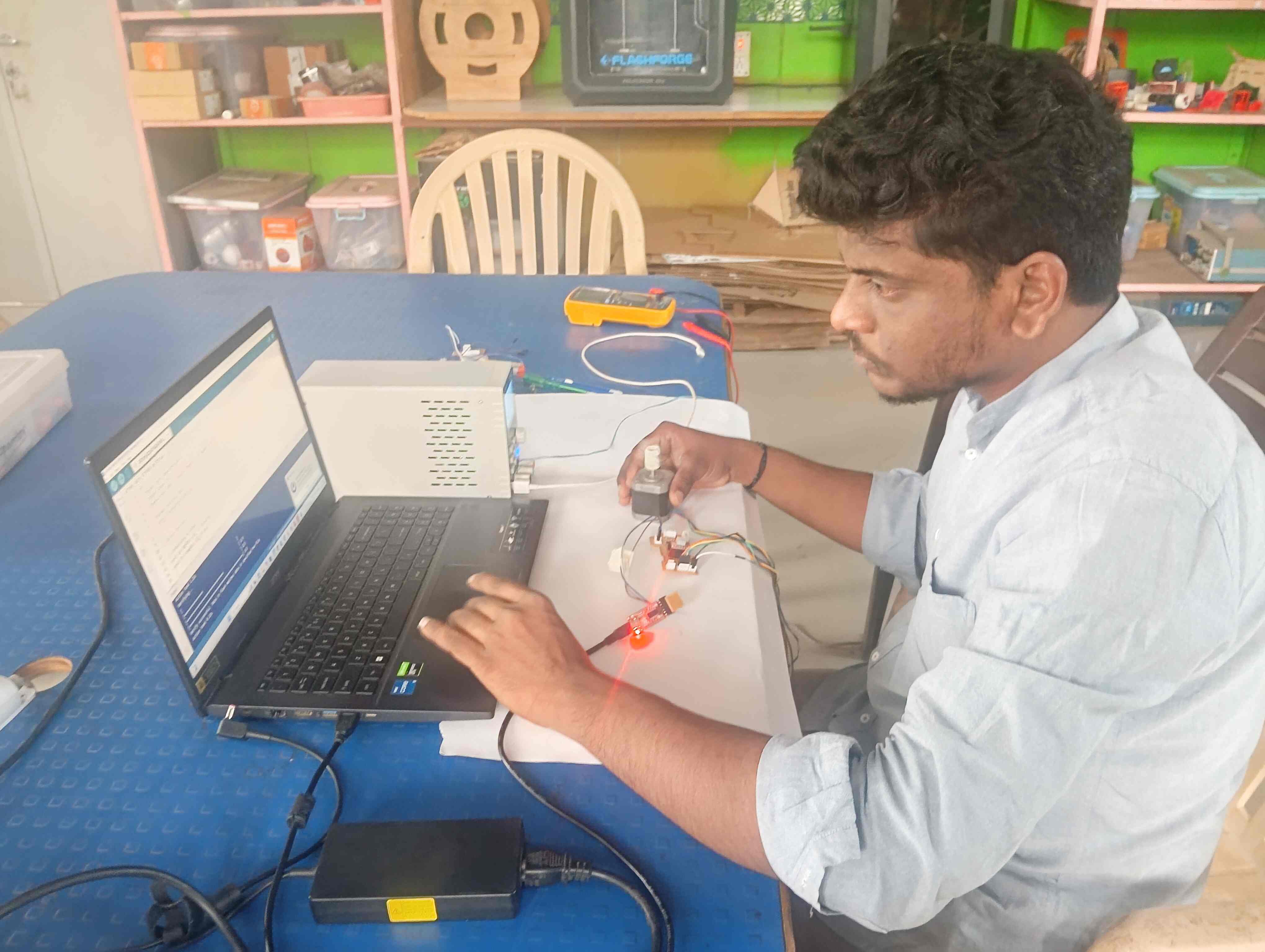
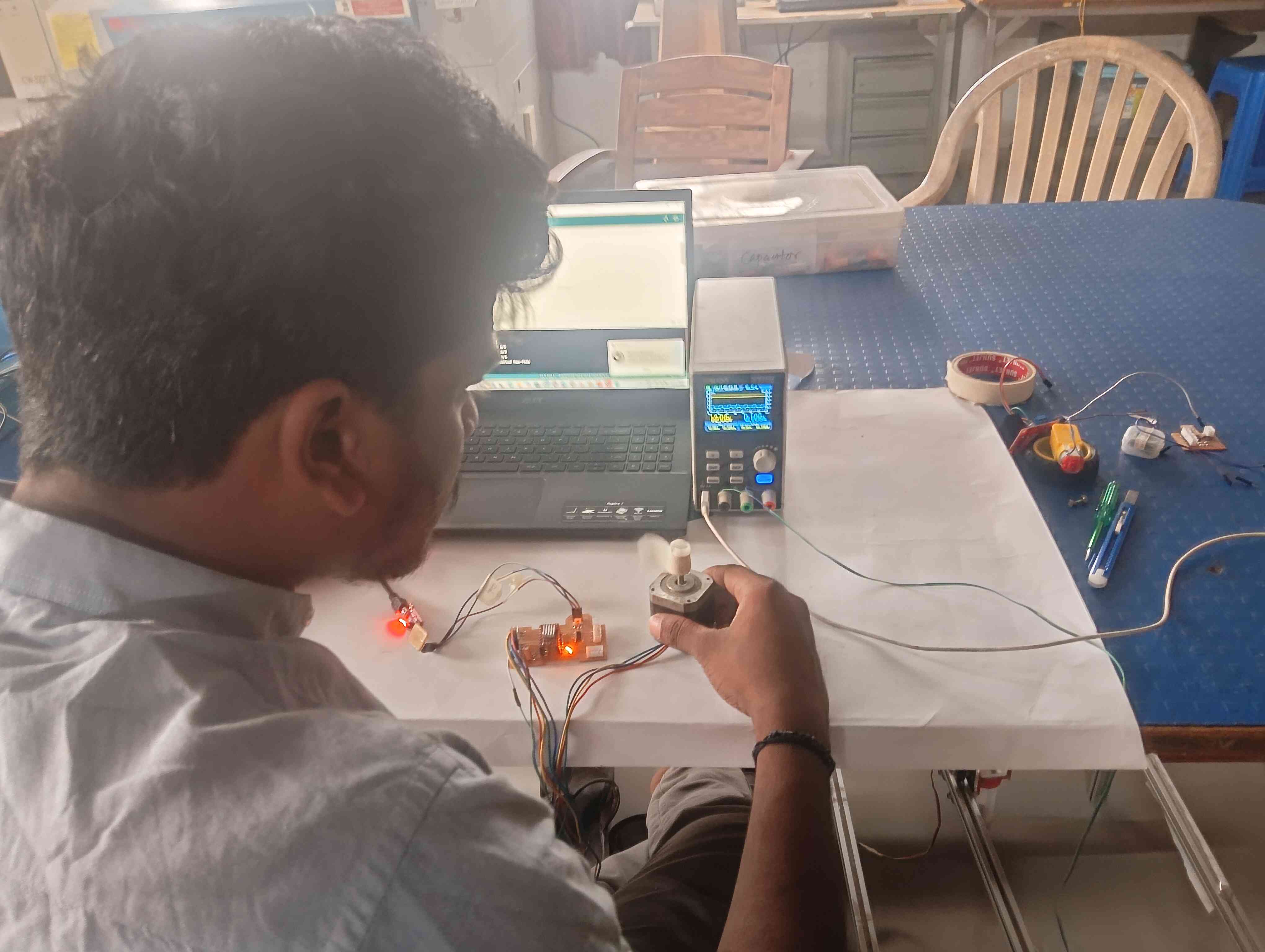
After that, I connected the stepper motor to my board. I then started programming the board to control the motor's movement. This allowed me to test the motor and ensure it was functioning properly.
|
|
|
Troubleshooting with the stepper motor.
|
|
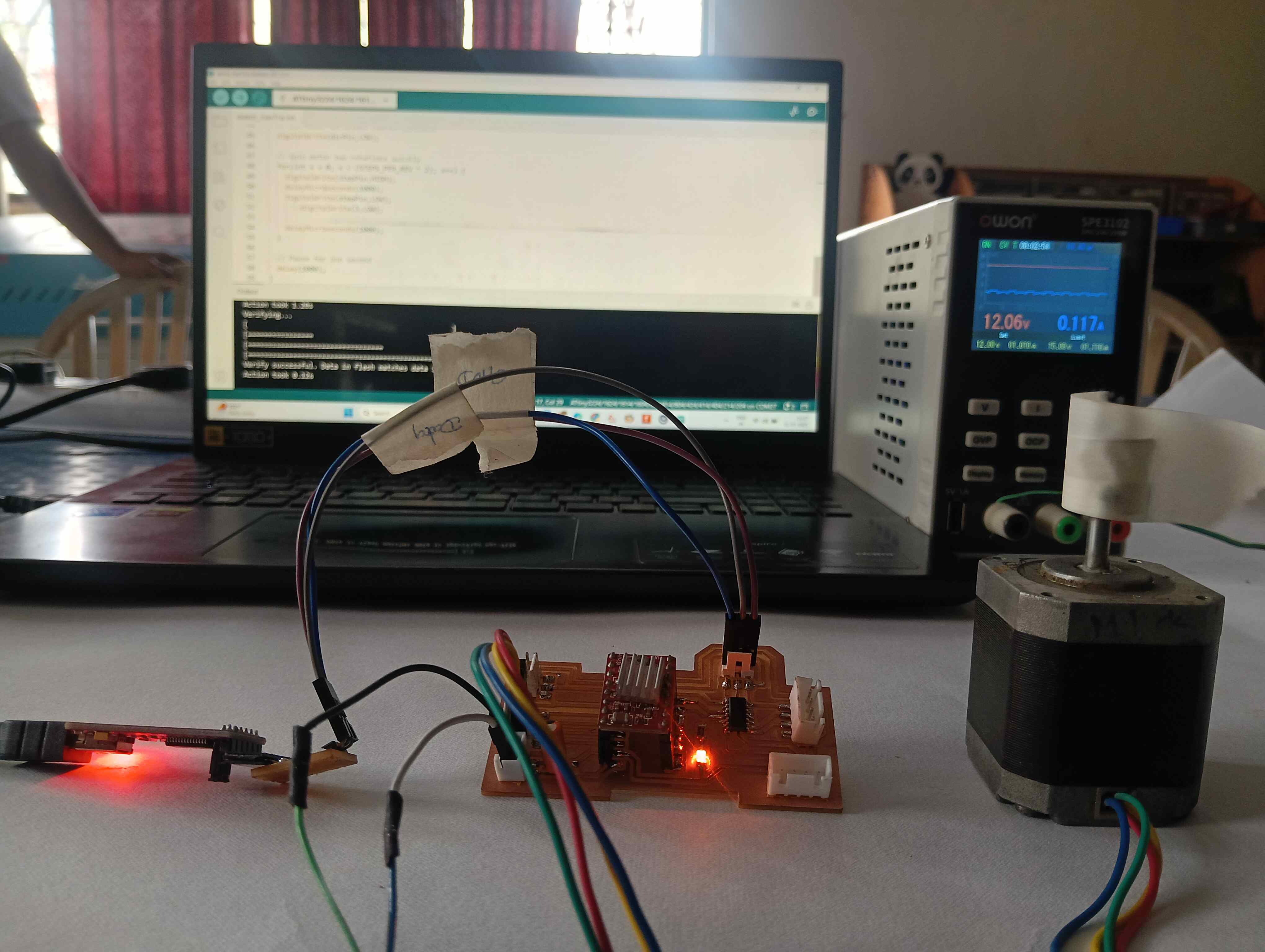
Working video
In the above video, I demonstrate the working of a NEMA 17 stepper motor controlled by an ATtiny microcontroller. I used an A4988 stepper motor driver to drive the motor efficiently. The ATtiny generates the required step pulses and direction control signals for the A4988. Proper wiring and current adjustment on the driver ensure smooth motor operation. This setup is useful for compact and low-power stepper motor applications.
A4988 stepper motor driver
The A4988 stepper motor driver is a compact module used to control bipolar stepper motors with microstepping support. It regulates motor movement by receiving step and direction signals from a microcontroller, while its built-in current limiting and overheat protection ensure safe operation. Adjustable VREF allows precise control of motor current, improving efficiency and performance.
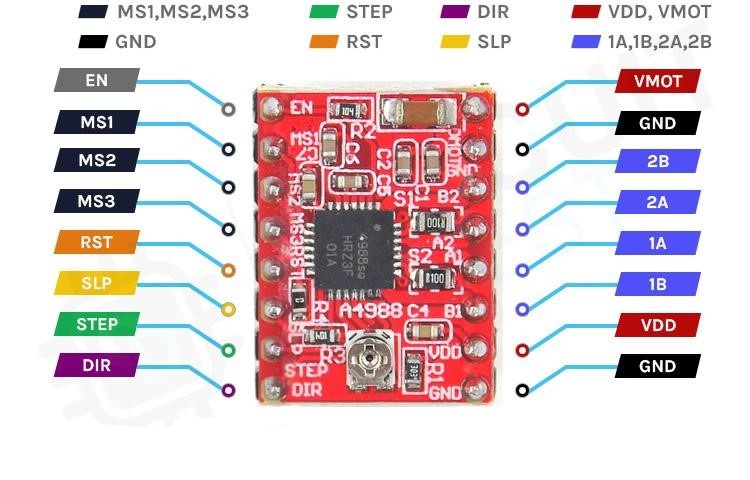
References: Reference
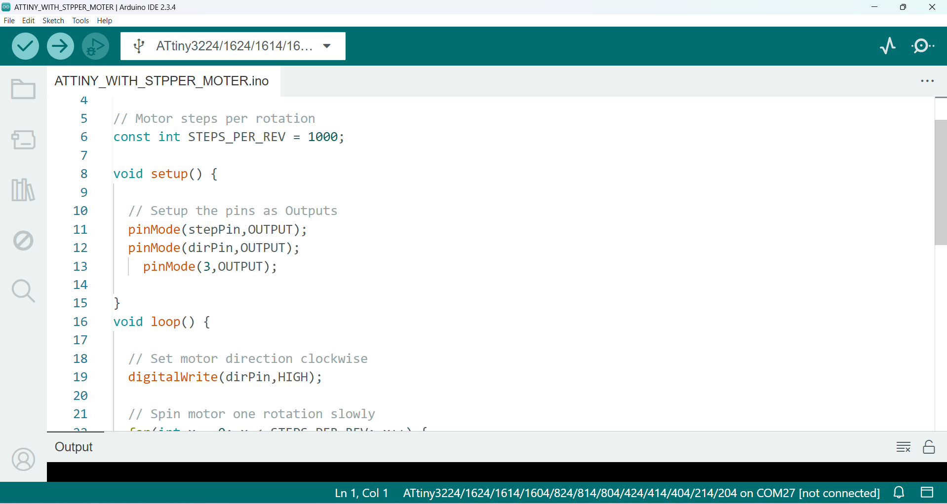
Arduino Code: STPPER MOTOR WITH ATTINY1614
const int dirPin = 1;  // Direction
const int stepPin = 2; // Step

// Motor steps per rotation
const int STEPS_PER_REV = 1000;

void setup() {

// Setup the pins as Outputs
pinMode(stepPin,OUTPUT);
pinMode(dirPin,OUTPUT);
  pinMode(3,OUTPUT);

}
void loop() {

// Set motor direction clockwise
digitalWrite(dirPin,HIGH);

// Spin motor one rotation slowly
for(int x = 0; x < STEPS_PER_REV; x++) {
  digitalWrite(stepPin,HIGH);
  delayMicroseconds(2000);
  digitalWrite(stepPin,LOW);
  digitalWrite(3,HIGH);
  delayMicroseconds(2000);
}

// Pause for one second
delay(1000);

// Set motor direction counterclockwise
digitalWrite(dirPin,LOW);

// Spin motor two rotations quickly
for(int x = 0; x < (STEPS_PER_REV * 2); x++) {
  digitalWrite(stepPin,HIGH);
  delayMicroseconds(1000);
  digitalWrite(stepPin,LOW);
      digitalWrite(3,LOW);

  delayMicroseconds(1000);
}

// Pause for one second
delay(1000);
}