Assignment 4: Embedded Programming
This assignment focuses on documenting my learning journey in Embedded Programming. It covers my understanding of fundamental concepts such as microcontroller architectures, memory organization, peripheral integration, word size, microcontroller families, and packaging types. As part of the individual task, I studied the datasheet of the microcontroller used in my custom-designed board and used a programmer to upload code and make it perform specific tasks. I explored multiple programming languages to work with various boards, including my custom board, Arduino Uno, and ESP32. I have also reflected on the positive outcomes achieved and the challenges I faced during this process. Additionally, I’ve included insights on what I would approach differently in future assignments and summarized the key lessons learned throughout this experience.
Highlight Moments of the Week
|
|
|

|
Basics of Embedded Programming :
Embedded programming is all about writing code that runs on small, specialized devices called microcontrollers. These devices are the "brains" of many machines, from washing machines to drones. Unlike regular computers, embedded systems are made to do just one job — but they do it very efficiently. Programming them means you need to understand how the hardware works and how your code controls it. You work closely with memory, input/output pins, and communication protocols like UART, I2C, or SPI. The code is usually written in C or C++, and sometimes in Python or Assembly depending on the system. It’s important to manage resources carefully since embedded systems often have limited memory and processing power. You also need to read datasheets to understand how each component behaves. Testing and debugging are key because small mistakes can stop the whole system from working. Overall, it’s about making software that reliably controls physical hardware in real-time.
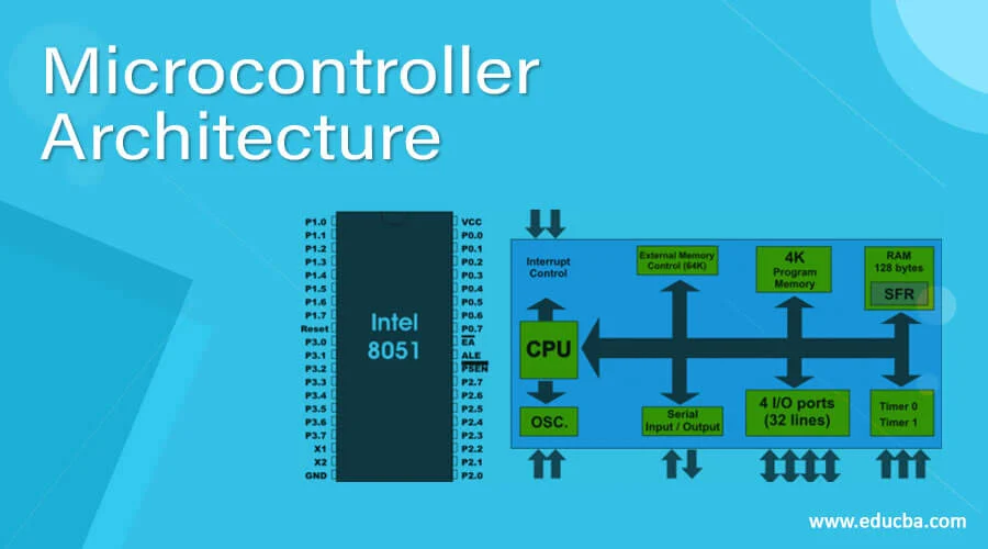
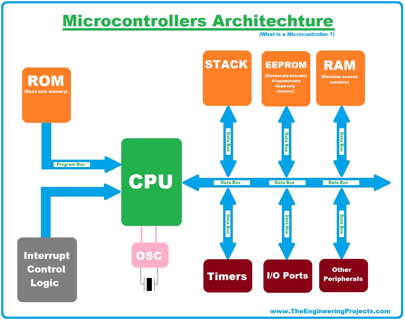
Microcontroller Architectures :Microcontroller architecture defines how a microcontroller’s memory and processing parts are arranged. The two main types are Harvard and Von Neumann. Harvard architecture uses separate memory for code and data, allowing faster operation. Von Neumann architecture shares one memory for both, making it simpler but slower. Knowing the architecture helps in choosing the right microcontroller and writing efficient programs. for More information
References: Reference
Memory :Memory in embedded systems is used to store both the program (code) and data. The main types are Flash, SRAM, and EEPROM. Flash stores the program and is non-volatile, meaning it keeps data even when power is off. SRAM is used for temporary data while the program runs, and EEPROM stores small amounts of data permanently. Understanding memory types helps manage storage and improve system performance. for More information
References: Reference
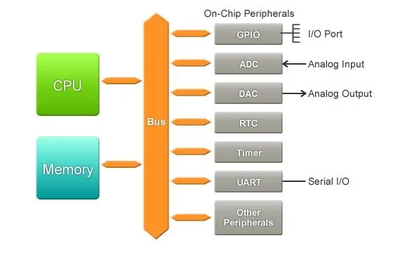
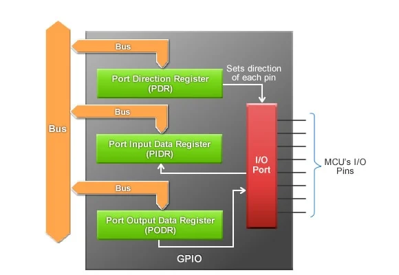
Peripherals :Peripherals are the input and output features of a microcontroller that let it interact with the outside world. Common peripherals include GPIO (for digital input/output), ADC (for reading analog signals), and PWM (for controlling motors or LEDs). Communication peripherals like UART, SPI, and I2C help connect the microcontroller to other devices. These built-in modules save space and make designs simpler. Knowing how to use peripherals is key to building functional embedded systems. for More information
|
|
References: Reference
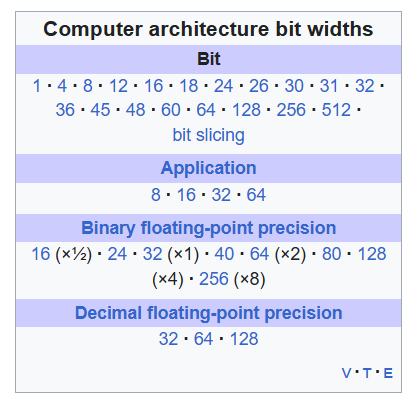
Word size :Word size refers to the number of bits a microcontroller can process in one operation—common sizes are 8-bit, 16-bit, and 32-bit. It affects the speed, memory access, and how much data can be handled at once. For example, an 8-bit microcontroller processes 8 bits at a time, which is enough for simple tasks. Larger word sizes (like 32-bit) are better for complex applications with more data. Choosing the right word size helps balance performance and cost in embedded projects. for More information
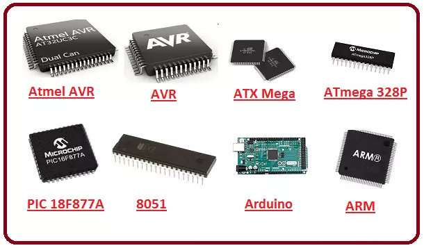
Microcontroller Families : Microcontroller families are groups of MCUs with shared architecture, toolchains, and feature sets—examples include AVR, PIC, and ARM Cortex.
AVR (e.g., ATmega328P) is popular in hobbyist boards like Arduino for its simplicity and ease of use. PIC microcontrollers from Microchip offer a wide range of performance and low-power options, often used in industrial applications.
ARM Cortex (M0, M3, M4, etc.) provides high performance and rich peripherals, common in advanced embedded and IoT projects.
Choosing a family depends on factors like processing needs, power consumption, development tools, and community support.
for More information
References: Reference
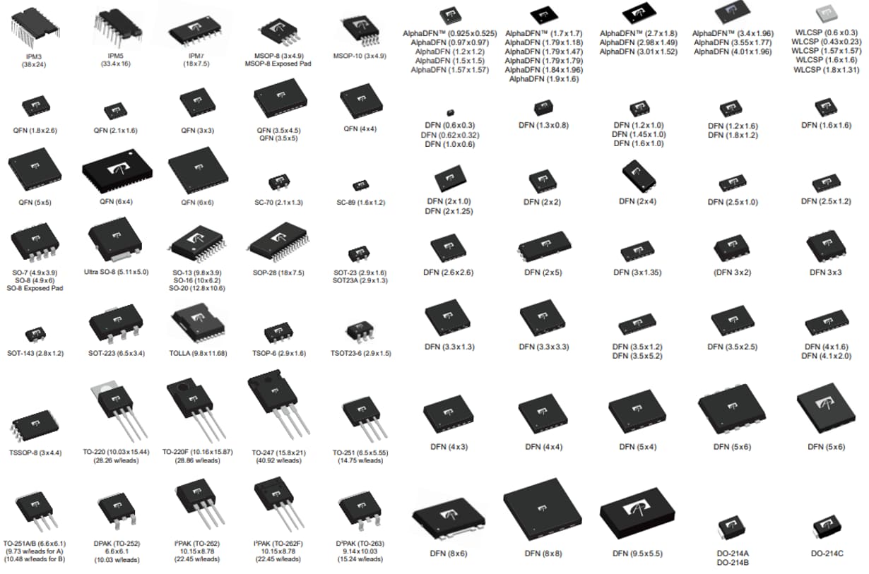
Packages:Integrated circuits and certain other electronic components are put into protective packages to allow easy handling and assembly onto printed circuit boards and to protect the devices from damage. A very large number of package types exist. Some package types have standardized dimensions and tolerances, and are registered with trade industry associations such as JEDEC and Pro Electron. Other types are proprietary designations that may be made by only one or two manufacturers. Integrated circuit packaging is the last assembly process before testing and shipping devices to customers. for More information
References: Reference
Embedded System :
An embedded system is a specialized computer system—a combination of a computer processor, computer memory, and input/output peripheral devices—that has a dedicated function within a larger mechanical or electronic system.[1][2] It is embedded as part of a complete device often including electrical or electronic hardware and mechanical parts. Because an embedded system typically controls physical operations of the machine that it is embedded within, it often has real-time computing constraints. Embedded systems control many devices in common use.[3] In 2009, it was estimated that ninety-eight percent of all microprocessors manufactured were used in embedded systems. for More information
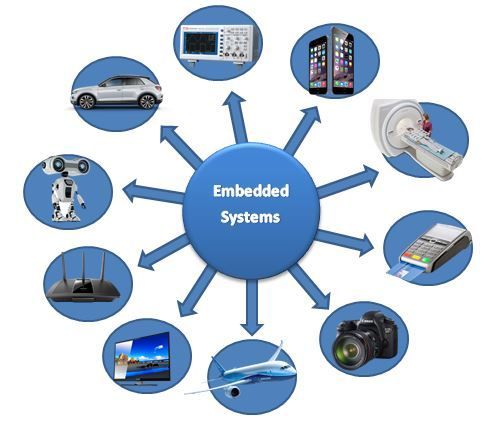
Applications of Embedded Systems :
Embedded systems are used in almost every modern electronic device around us. They are built to perform specific tasks efficiently and reliably. Here are some common application areas:
Consumer Electronics: Devices like televisions, washing machines, microwave ovens, and smart home gadgets use embedded systems to automate functions.
Automotive Systems: Embedded systems control features such as anti-lock braking (ABS), airbags, engine control units (ECUs), and infotainment systems.
Medical Devices: Instruments like pacemakers, digital thermometers, insulin pumps, and ECG machines rely on embedded systems for precise operation.
Industrial Automation: Used in robotics, factory control systems, temperature regulation, and machinery monitoring.
Communication Devices: Embedded systems are present in routers, modems, and mobile phones to handle data and connectivity functions.
Aerospace and Defense: Critical systems like flight controllers, missile guidance systems, and surveillance drones depend on embedded control.
Source: Reference
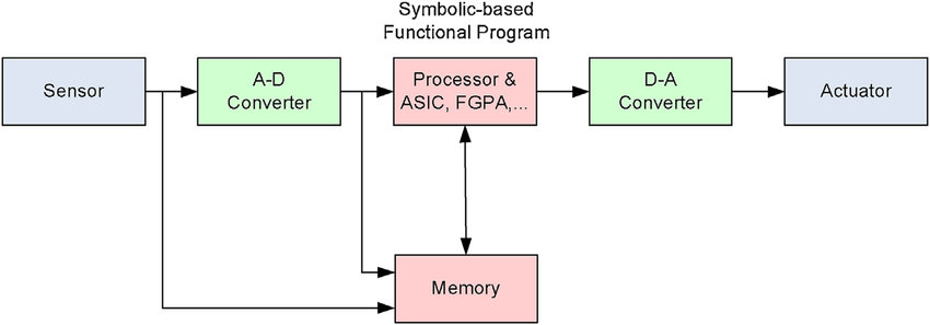
Structure of Embedded Systems
The structure of an embedded system includes various components that work together to carry out a specific task. These components are:Sensor/Input Devices: Collect real-world data like temperature, pressure, or light.
Processor/Microcontroller: Processes input data and makes decisions based on the program logic.
Memory: Includes ROM/Flash for program storage and RAM for temporary data processing.
Actuator/Output Devices: Carry out actions such as turning on LEDs, motors, or sending data.
Communication Interfaces: Enable communication with other systems via UART, SPI, I2C, etc.
Software/Firmware: The embedded code that defines how the system operates and responds to inputs.
Source: Reference
References: Reference
Introduction to Embedded Systems
Microcontroller :
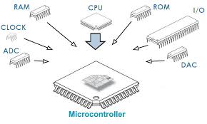
A microcontroller (MC, uC, or μC) or microcontroller unit (MCU) is a small computer on a single integrated circuit. A microcontroller contains one or more CPUs (processor cores) along with memory and programmable input/output peripherals. Program memory in the form of NOR flash, OTP ROM, or ferroelectric RAM is also often included on the chip, as well as a small amount of RAM. Microcontrollers are designed for embedded applications, in contrast to the microprocessors used in personal computers or other general-purpose applications consisting of various discrete chips.
In modern terminology, a microcontroller is similar to, but less sophisticated than, a system on a chip (SoC). A SoC may include a microcontroller as one of its components but usually integrates it with advanced peripherals like a graphics processing unit (GPU), a Wi-Fi module, or one or more coprocessors.
Microcontrollers are used in automatically controlled products and devices, such as automobile engine control systems, implantable medical devices, remote controls, office machines, appliances, power tools, toys, and other embedded systems. By reducing the size and cost compared to a design that uses a separate microprocessor, memory, and input/output devices, microcontrollers make digital control of more devices and processes practical. Mixed-signal microcontrollers are common, integrating analog components needed to control non-digital electronic systems. In the context of the Internet of Things, microcontrollers are an economical and popular means of data collection, sensing and actuating the physical world as edge devices.
for More information
|
|
References: Reference1, Reference2
Microprocessor
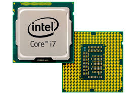
A microprocessor is a computer processor for which the data processing logic and control is included on a single integrated circuit (IC), or a small number of ICs. The microprocessor contains the arithmetic, logic, and control circuitry required to perform the functions of a computer's central processing unit (CPU). The IC is capable of interpreting and executing program instructions and performing arithmetic operations.[1] The microprocessor is a multipurpose, clock-driven, register-based, digital integrated circuit that accepts binary data as input, processes it according to instructions stored in its memory, and provides results (also in binary form) as output. Microprocessors contain both combinational logic and sequential digital logic, and operate on numbers and symbols represented in the binary number system.
The integration of a whole CPU onto a single or a few integrated circuits using Very-Large-Scale Integration (VLSI) greatly reduced the cost of processing power. Integrated circuit processors are produced in large numbers by highly automated metal–oxide–semiconductor (MOS) fabrication processes, resulting in a relatively low unit price. Single-chip processors increase reliability because there are fewer electrical connections that can fail. As microprocessor designs improve, the cost of manufacturing a chip (with smaller components built on a semiconductor chip the same size) generally stays the same according to Rock's law.
for More information
|
|
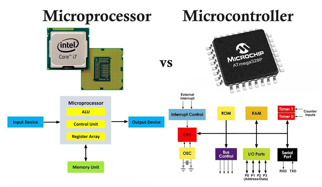
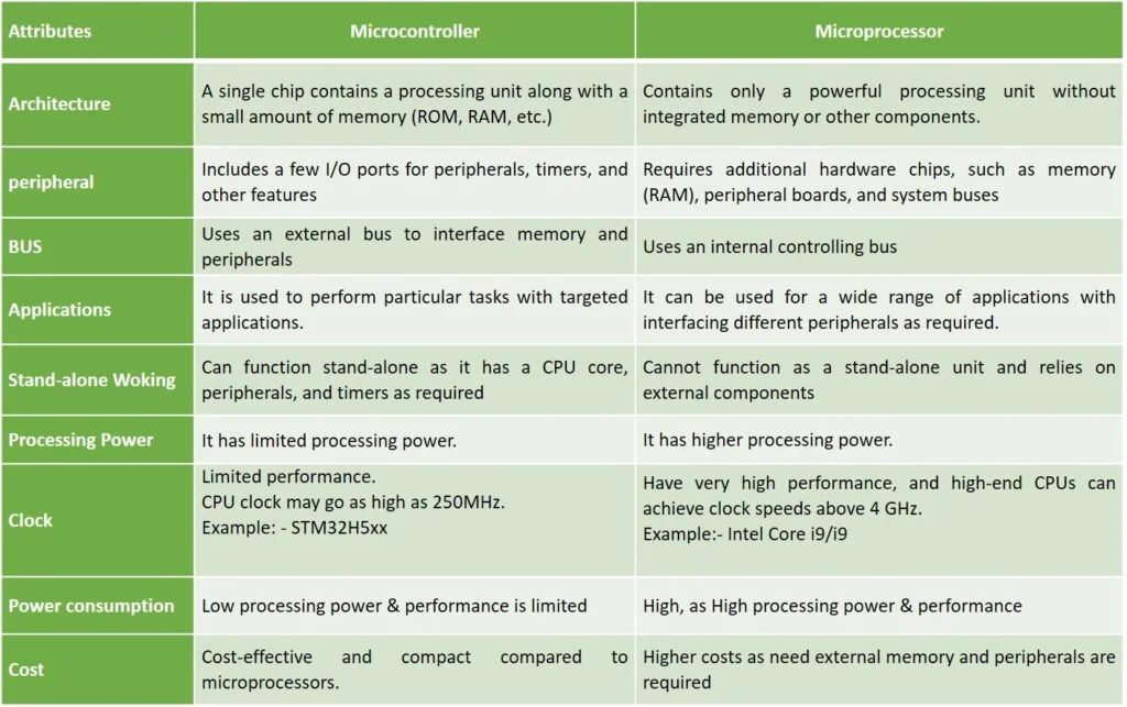
Difference between microcontroller and microprocessor
A microcontroller is a compact, integrated device that combines a CPU, memory (both RAM and Flash), and I/O ports on a single chip, designed to perform specific tasks. It is commonly used in embedded systems where efficiency, size, and low power consumption are essential. On the other hand, a microprocessor consists only of the CPU and requires additional external components such as memory and I/O controllers to function. Microcontrollers are cost-effective and optimized for real-time applications, while microprocessors are more powerful, designed for complex tasks, and capable of running full operating systems. Microcontrollers are typically programmed in languages like C/C++, whereas microprocessors generally require an operating system and are often programmed in higher-level languages like Python or Java. Reference
References: Reference1, Reference2
Group Assignment
Objective of the Group Assignment
- Demonstrate and compare toolchains and development workflows for available embedded architectures.
- Document the work on the group work page and reflect on individual learning on a personal page.
Individual Assignment
Objective of the Individual Assignment:
- Review the datasheet of the assigned microcontroller.
- Write a program, simulate its operation, and interact with local input/output devices.
- Enable communication via wired or wireless connections.
For this assignment, I have chosen to work with both the Arduino Uno and the ESP32 microcontroller boards. To better understand how each controller works, I am studying their datasheets. This helps me gain a clearer understanding of their architecture, features, and how to use them effectively.
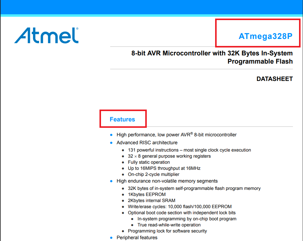
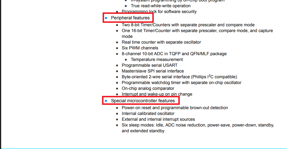
Reading Data sheets (ATmega328P) :
DataSheetBelow, I am sharing the topics I have studied so far. I focused on the features of the ATmega328P microcontroller, which is used in the Arduino Uno. In particular, I explored its peripheral features and special microcontroller functions to gain a better understanding of how it operates and interacts with various components.
|
|
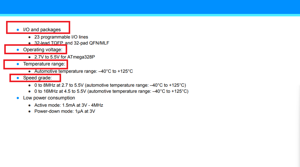
In the image below, I am focusing on key specifications of the ATmega328P microcontroller. These include I/O and package types, operating voltage, temperature range, and speed grade. I also noted its low power consumption, which is important for energy-efficient applications.
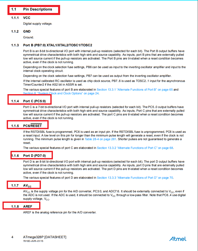
Below, I am showing the pin description of the ATmega328P microcontroller.
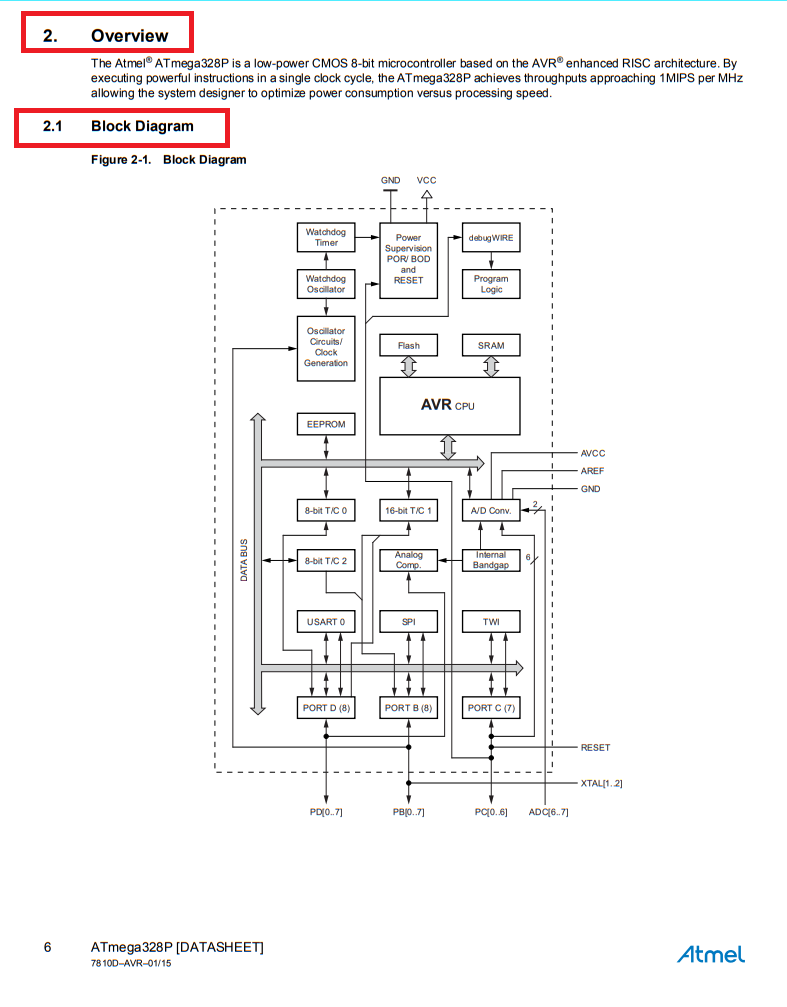
Below, I am showing how the pin configuration is arranged and presenting the block diagram of the ATmega328P microcontroller. This helps in understanding the internal structure and how each pin is connected to different functional blocks within the controller.
|
|
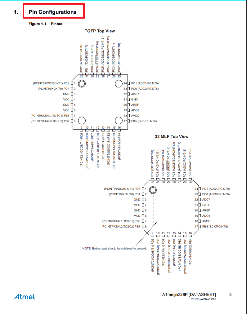
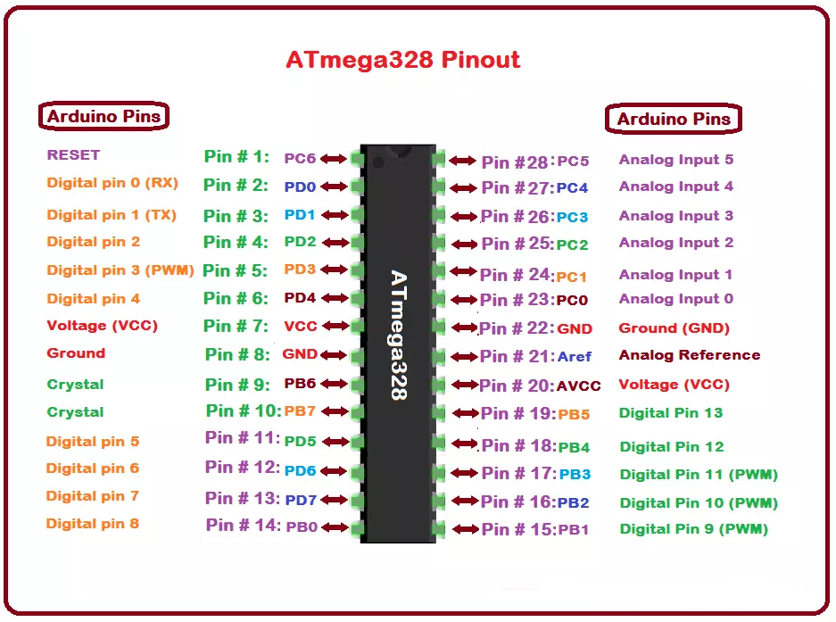
Below, I am showing the pinout of the ATmega328P microcontroller. This pinout diagram provides a visual representation of all the pins and their functions, such as power, ground, digital and analog I/O, and communication interfaces. It helps in understanding how to connect the microcontroller to other components in a circuit.
Reading Data sheets (ESP32-WROOM-32) :
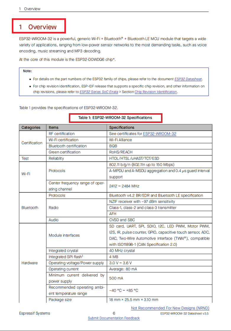
DataSheetNow coming to the ESP32-WROOM-32 datasheet, I have noted the important points that I observed. I have documented these key specifications in the image below, including the Overview and ESP32-WROOM-32 Specifications. These specifications are very important to understand before starting hands-on practice with the module.
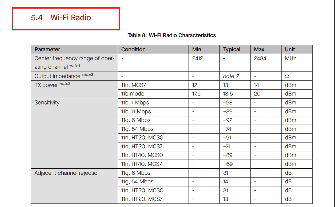
Below, I am showing the Wi-Fi radio characteristics of the ESP32-WROOM-32 module. This section provides important details about the wireless performance, such as frequency range, modulation, data rate, and sensitivity. Understanding these characteristics is essential for designing and testing wireless communication in real-world applications.
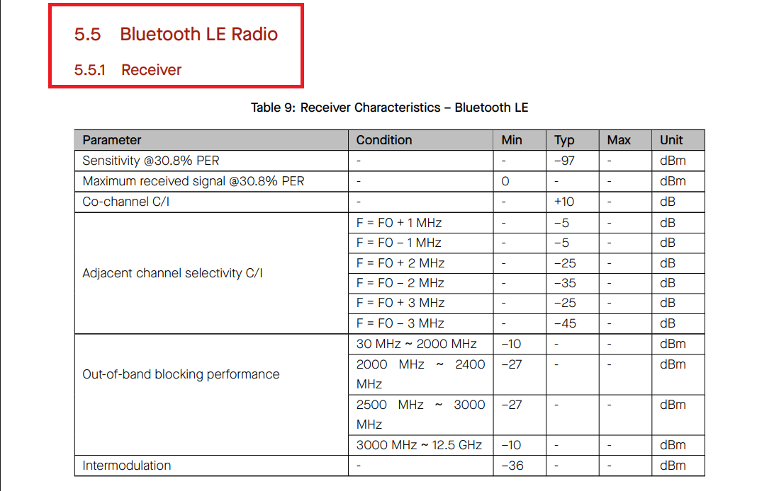
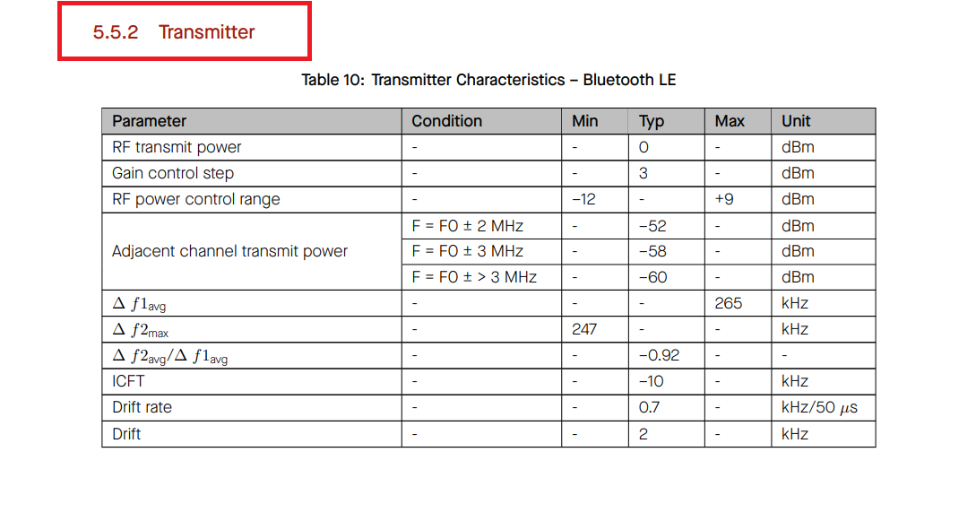
Below, I am showing the Receiver Characteristics – Bluetooth LE and Transmitter Characteristics – Bluetooth LE of the ESP32-WROOM-32 module. These sections provide important details about the Bluetooth Low Energy performance, including sensitivity, output power, and modulation accuracy. This information is useful when working on Bluetooth-based applications and ensuring reliable communication.
|
|
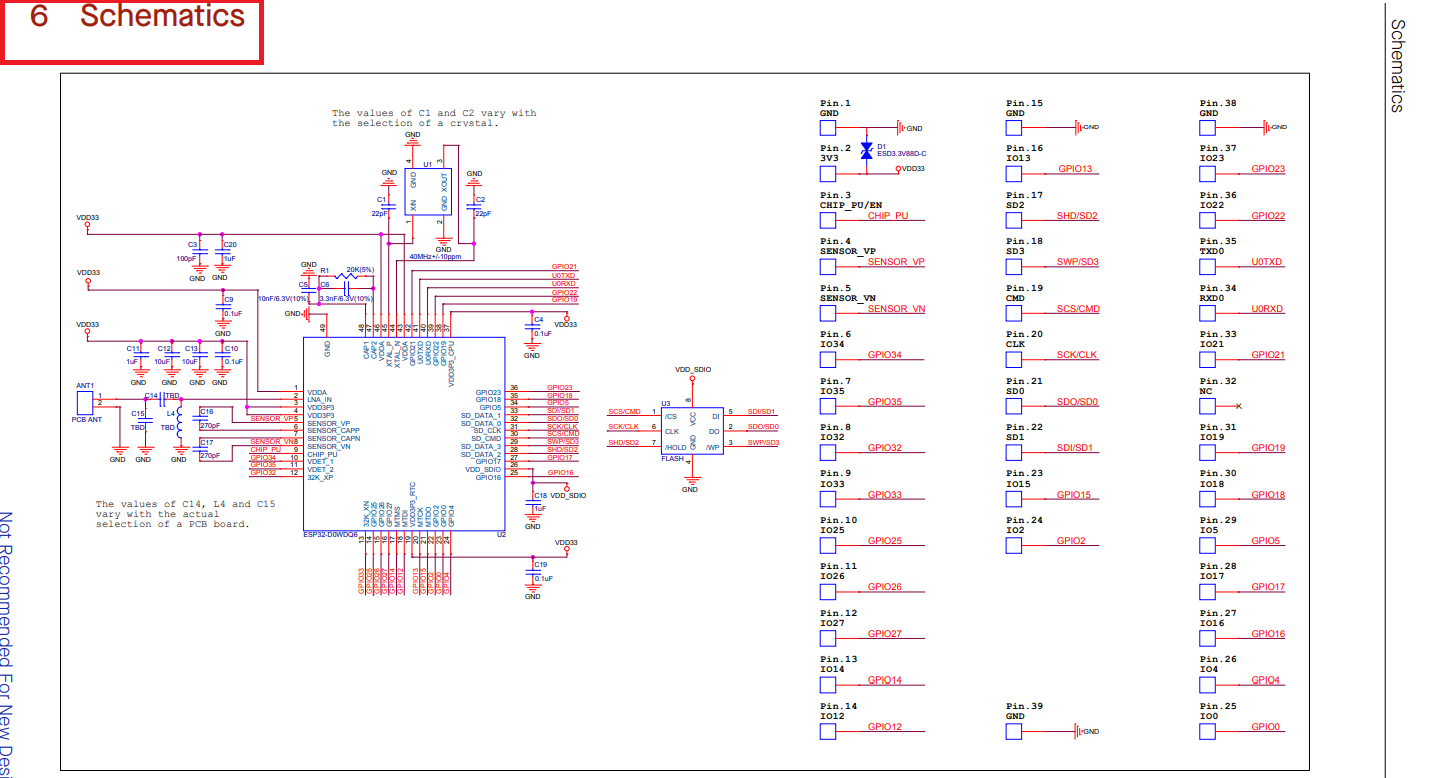
Below, I am showing the schematics of the ESP32-WROOM-32 module.
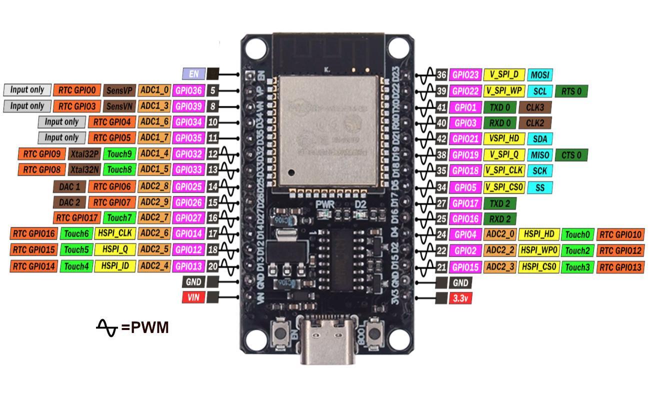
Here is the pinout for the ESP32-WROOM-32 module. This diagram shows the arrangement and function of each pin, including power, ground, digital I/O, analog inputs, and communication interfaces.
References: Reference
Program Development & Simulation :
After reading the datasheets for the ATmega328P and the ESP32-WROOM module, I began embedded programming for Task 2 of this assignment. I programmed the Arduino Uno to control multiple LEDs using the Serial Monitor. Additionally, I programmed the ESP32 DevKit module to read temperature and humidity data from a DHT22 sensor and displayed the readings on an LCD. I also used Processing software to control an LED on the custom-developed board via serial communication.
Controlling LEDs via Serial Monitor using Arduino Uno :
Below, I am explaining step by step how I controlled different LEDs via the Serial Monitor using the Arduino Uno. This process involves sending specific commands through the Serial Monitor, which are then interpreted by the Arduino to turn LEDs ON or OFF based on the input.
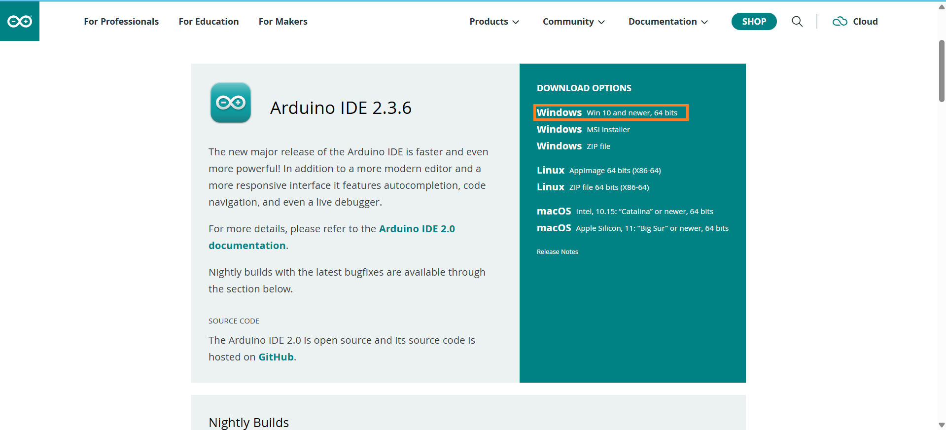
Step 1: First, I downloaded the Arduino IDE. Below, I am showing the process of how I installed it
|

|
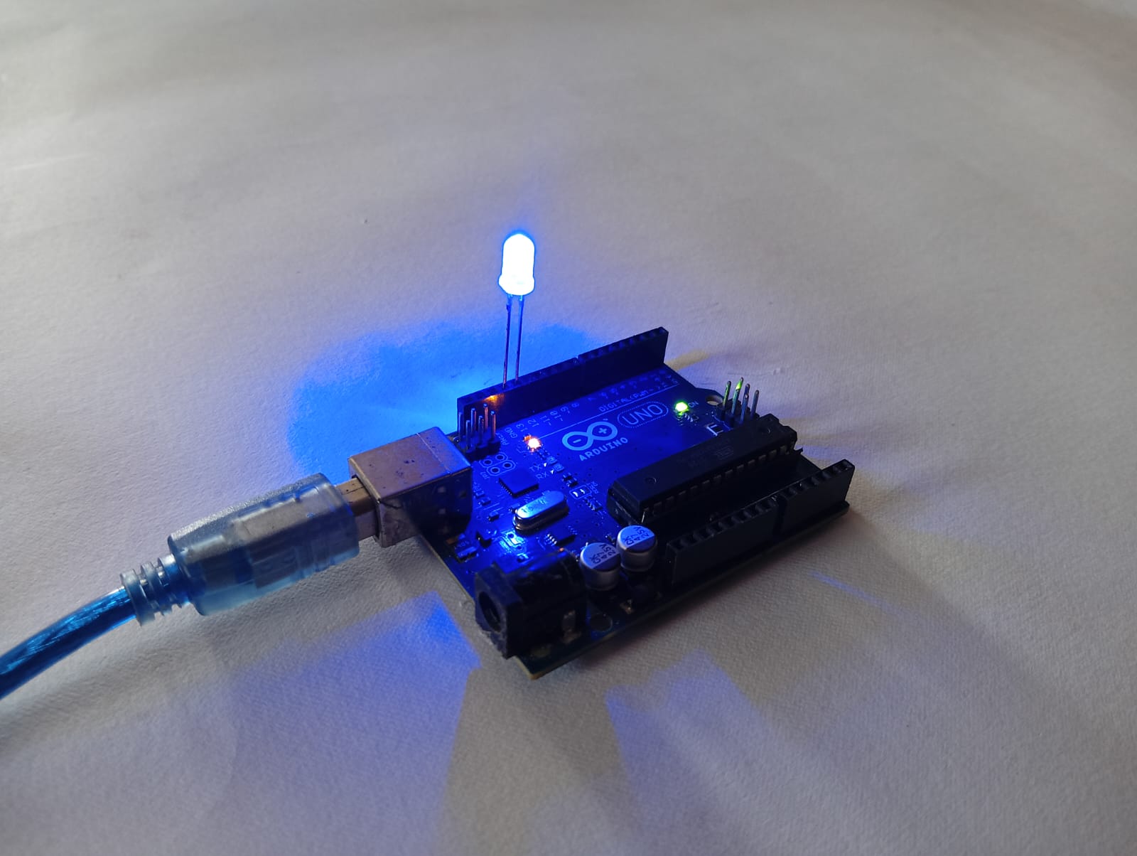
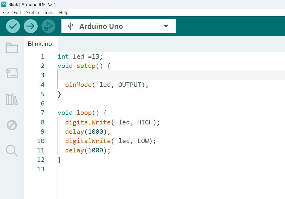
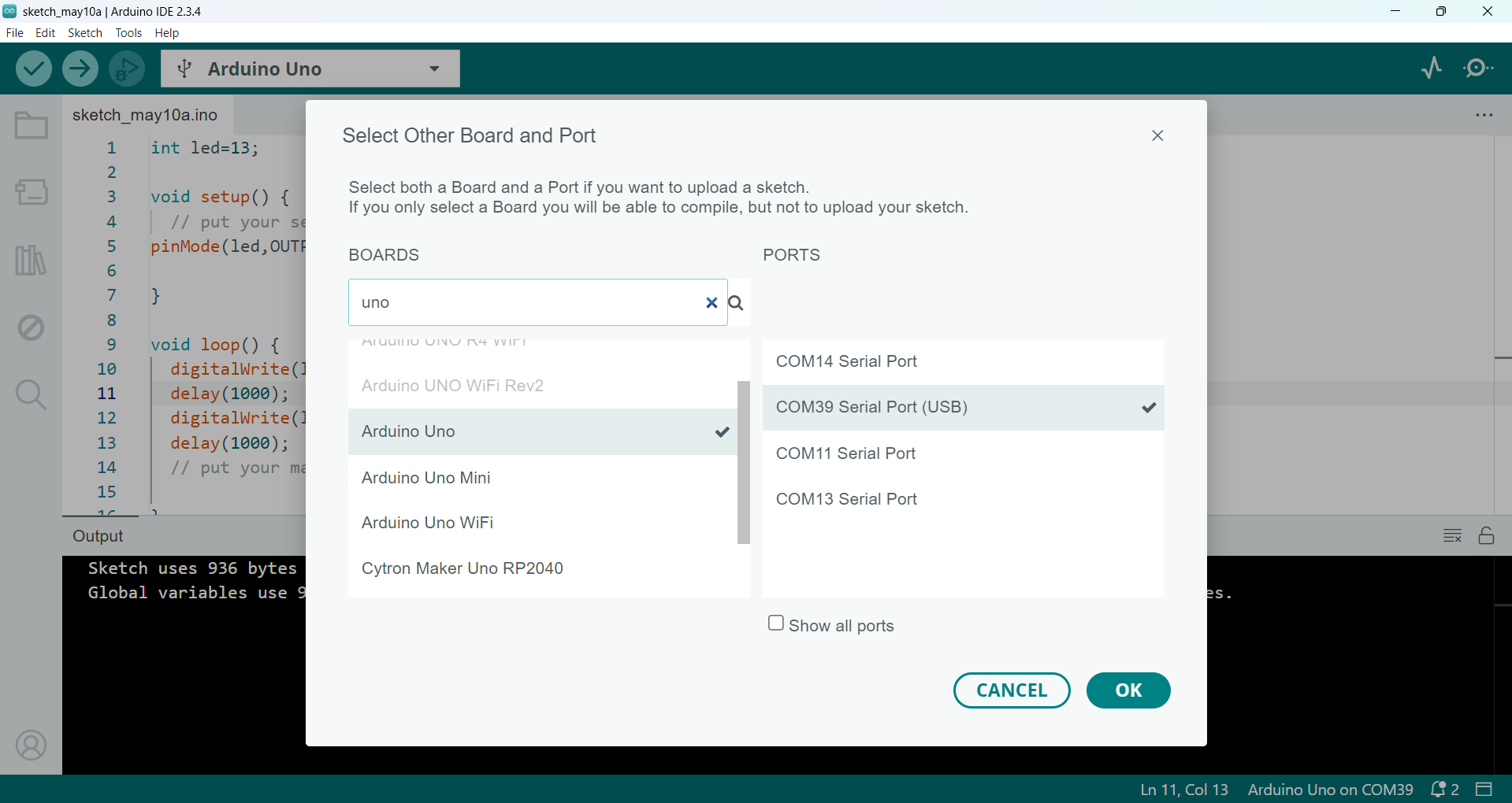
Step 2: After installing the Arduino IDE, I uploaded the Blink code to my Arduino board for testing purposes. You can find this code in the "Examples" section of the IDE. In my case, I have written the code, and below, I am showing the image of the code.
|
|
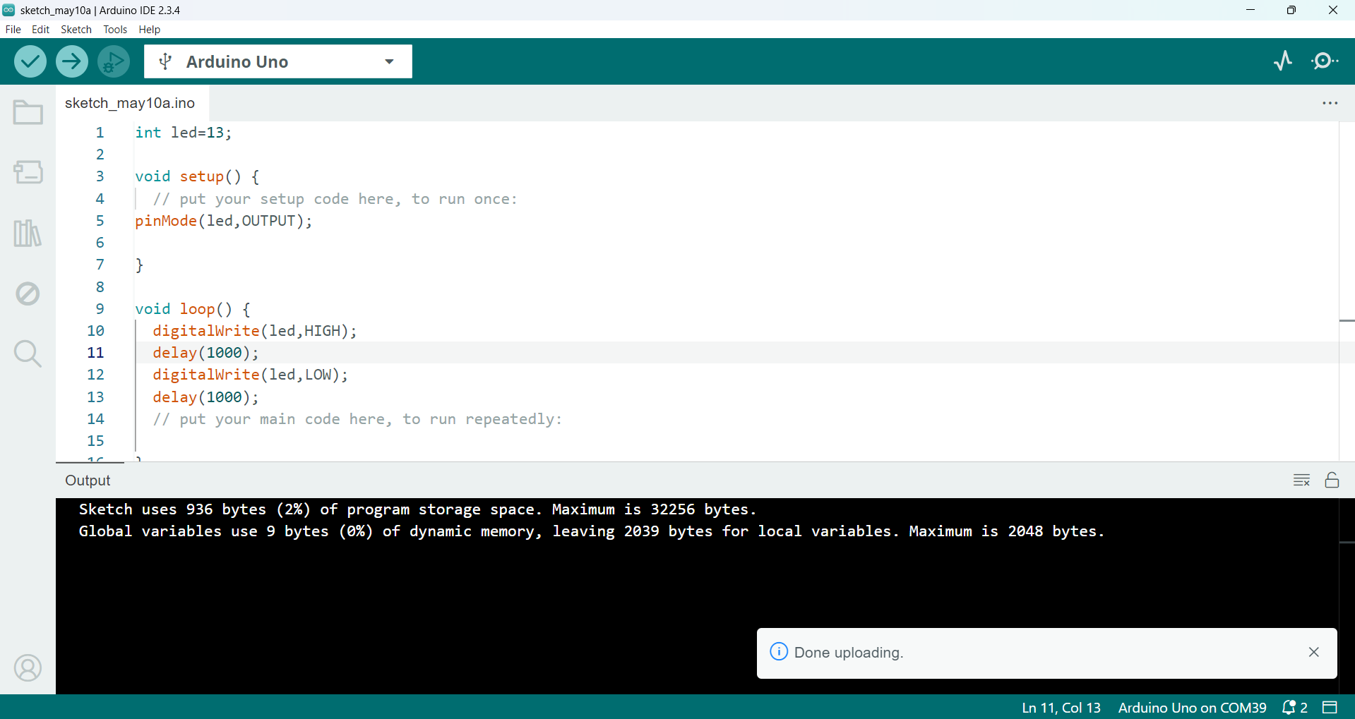
After uploading the code, I observed the results on the Arduino board. The output is shown in the image below.
|
|
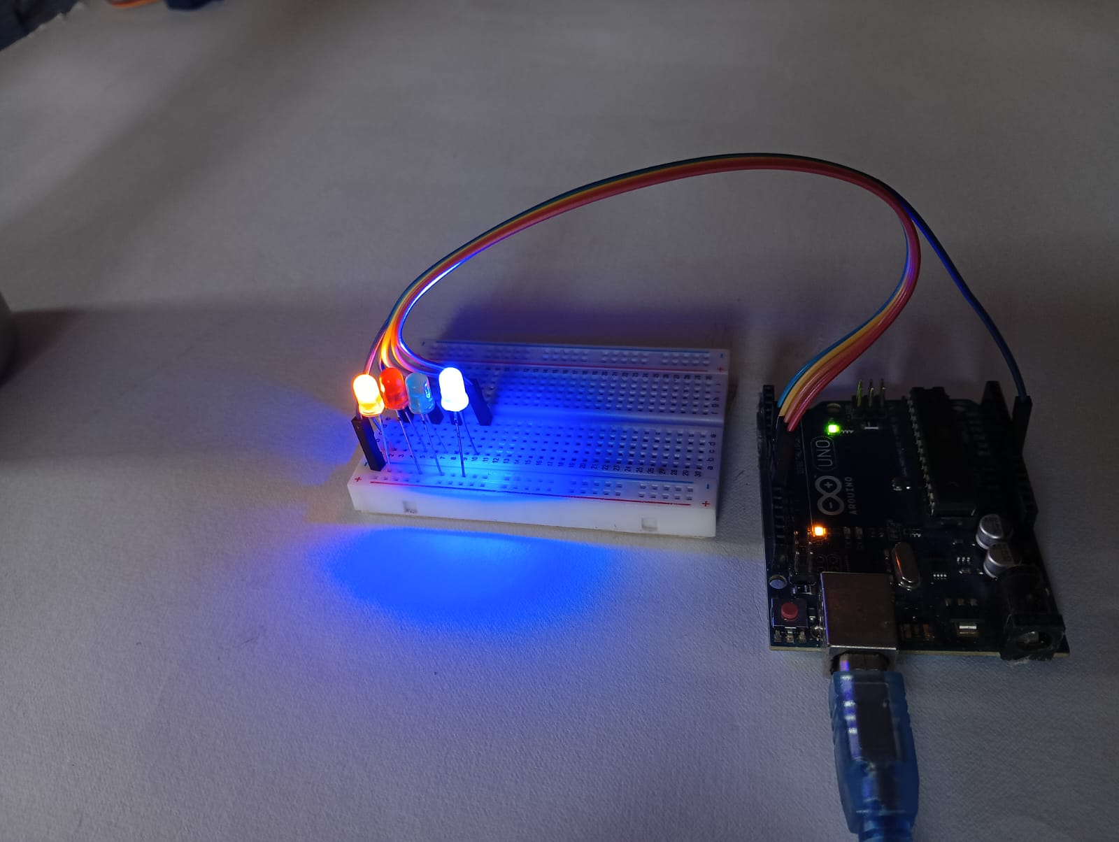
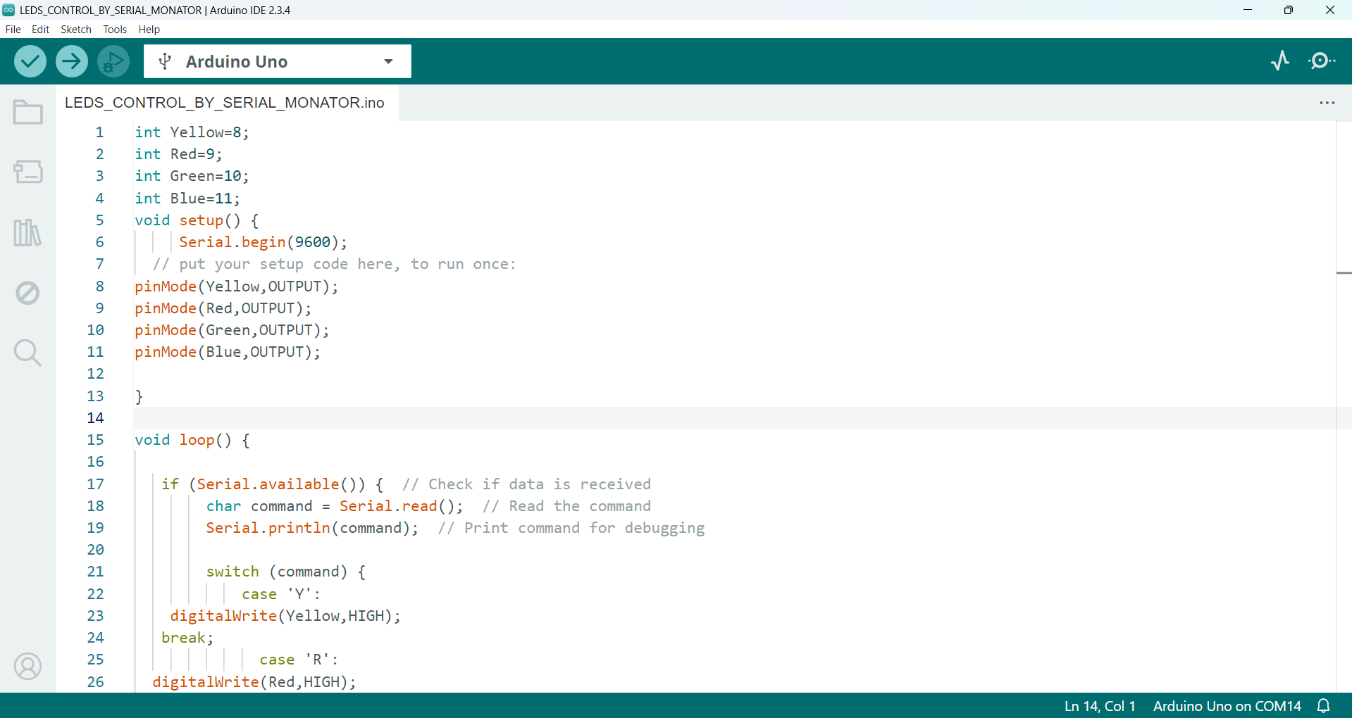
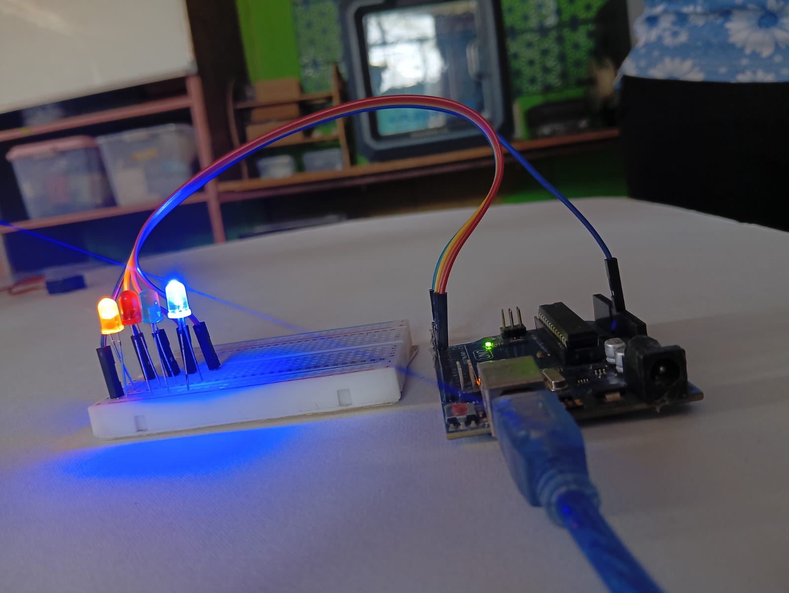
After successfully testing the blinking LED, I connected four LEDs to the Arduino Uno and started controlling them using the Serial Monitor. For this, I wrote a custom code that allows LED control based on user input from the Serial Monitor. I used Serial.begin() to start serial communication and Serial.available() to check for incoming data. I then used a switch statement to control each LED based on the input. The complete code is shown below.
|
|
Below, I am showing how I controlled the LED using the Serial Monitor. This demonstration includes the code, wiring connections, and how different inputs sent through the Serial Monitor turn the LED ON or OFF. It highlights how serial communication can be used for real-time control in embedded systems.
Arduino code for Controlling LEDs via Serial Monitor using Arduino Uno
int Yellow=8;
int Red=9;
int Green=10;
int Blue=11;
void setup() {
     Serial.begin(9600);
  // put your setup code here, to run once:
pinMode(Yellow,OUTPUT);
pinMode(Red,OUTPUT);
pinMode(Green,OUTPUT);
pinMode(Blue,OUTPUT);

}

void loop() {

   if (Serial.available()) {  // Check if data is received
        char command = Serial.read();  // Read the command
        Serial.println(command);  // Print command for debugging

        switch (command) {
            case 'Y':
    digitalWrite(Yellow,HIGH);
   break;
              case 'R':
  digitalWrite(Red,HIGH);
  break;
              case 'G':
    digitalWrite(Green,HIGH);
   break;
              case 'B':
  digitalWrite(Blue,HIGH);
  break;
  case 'O':
  digitalWrite(Yellow,LOW);
  digitalWrite(Red,LOW);
  digitalWrite(Green,LOW);
  digitalWrite(Blue,LOW);  break;
    case 'A':
  digitalWrite(Yellow,HIGH);
  digitalWrite(Red,HIGH);
  digitalWrite(Green,HIGH);
  digitalWrite(Blue,HIGH);  break;
  // put your main code here, to run repeatedly:

        }
        }
        }
Operating a Servo Motor via PyCharm :
After controlling the LEDs using the Serial Monitor, I decided to explore a different method. I chose to control a servo motor using Python in the PyCharm IDE. For this, I used the PyCharm Community Edition. Below, I explain step by step how I completed this task.
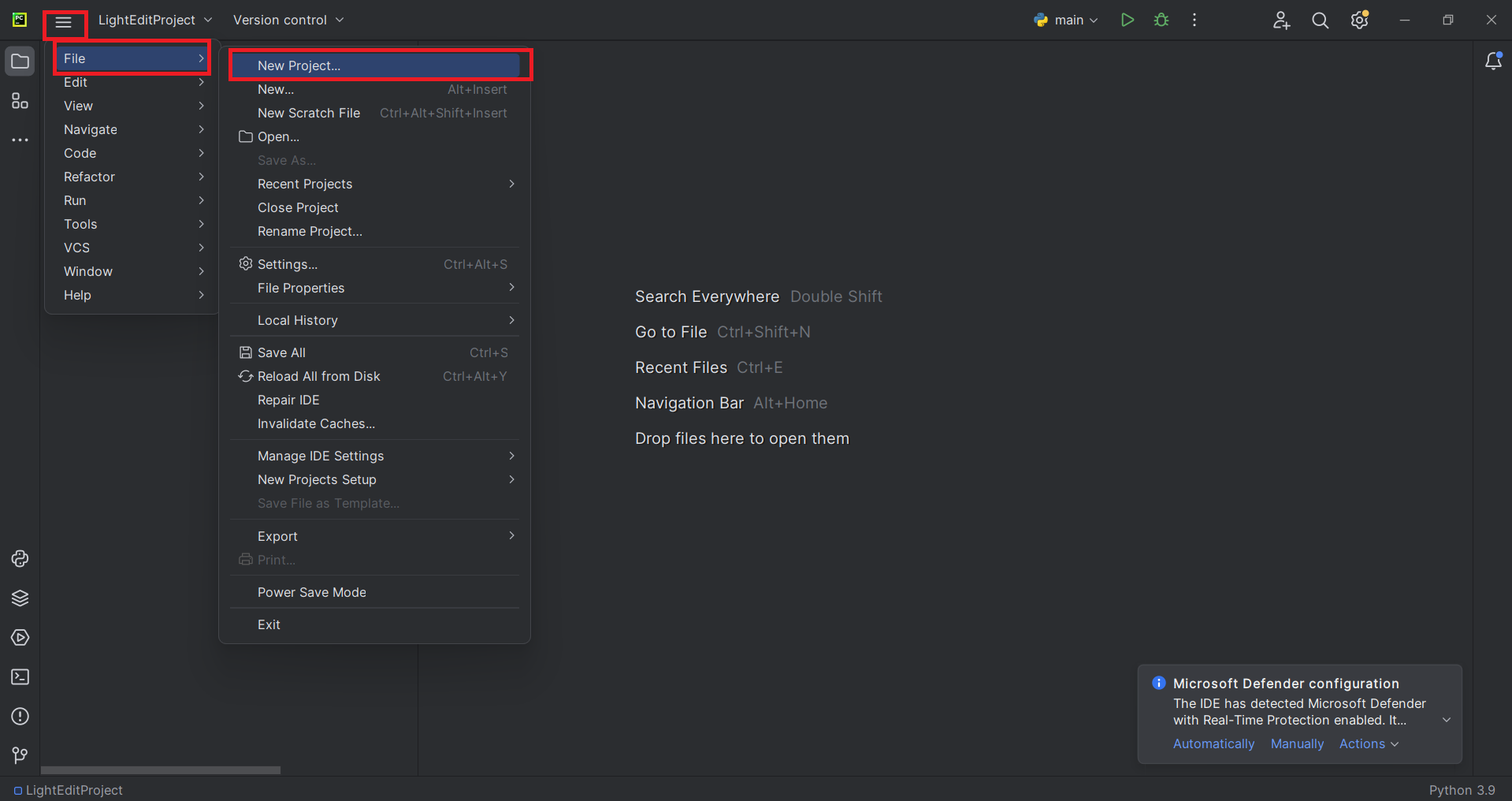
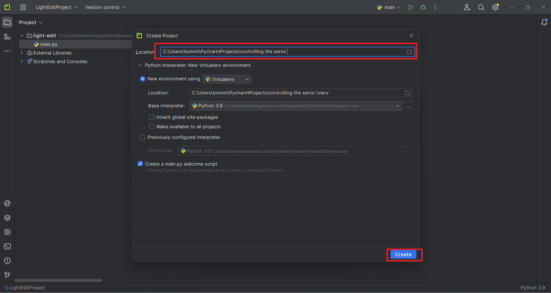
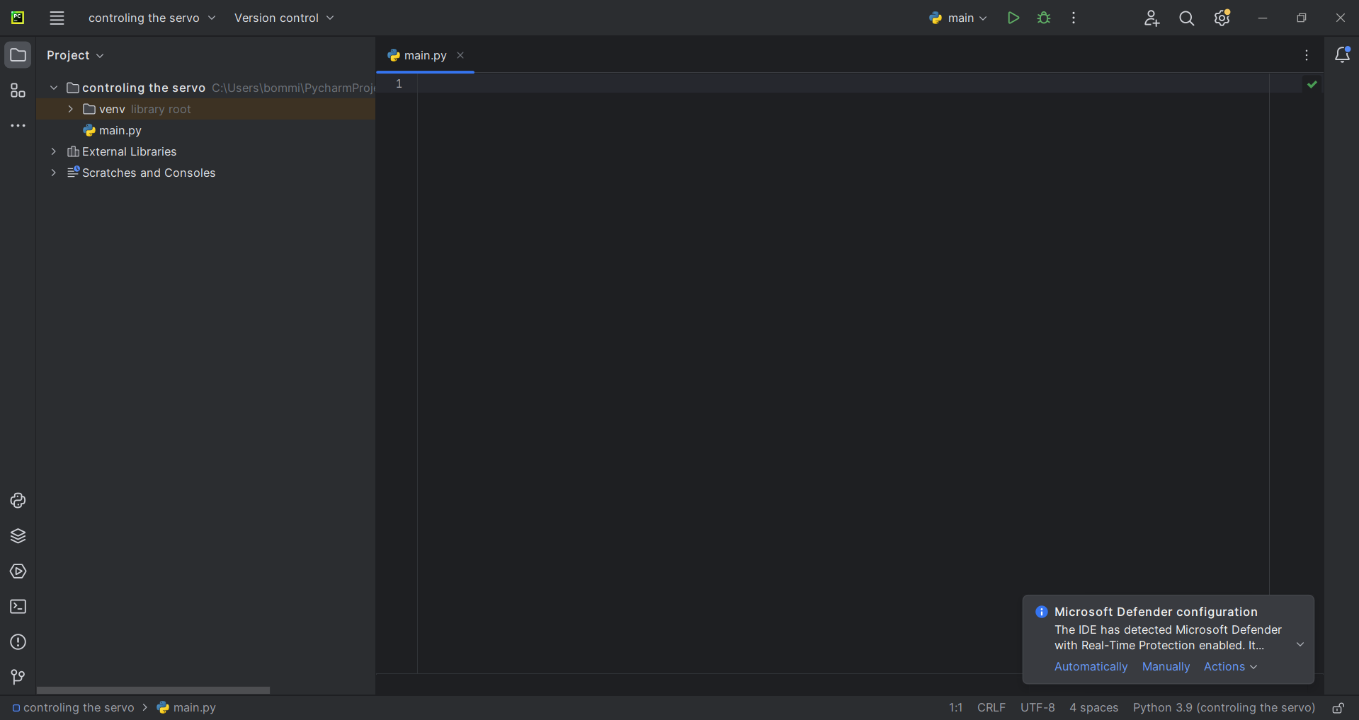
Step 1: I started writing the code in PyCharm. First, I created a new project in the PyCharm IDE.
|
|
Step 2: I connected the servo motor to the Arduino. The signal pin of the servo motor was connected to pin number 9 of the Arduino. Then i started writing the code in PyCharm
|
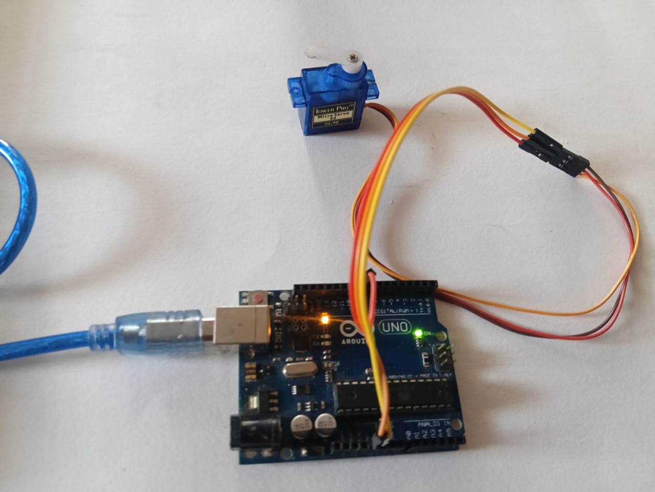
|
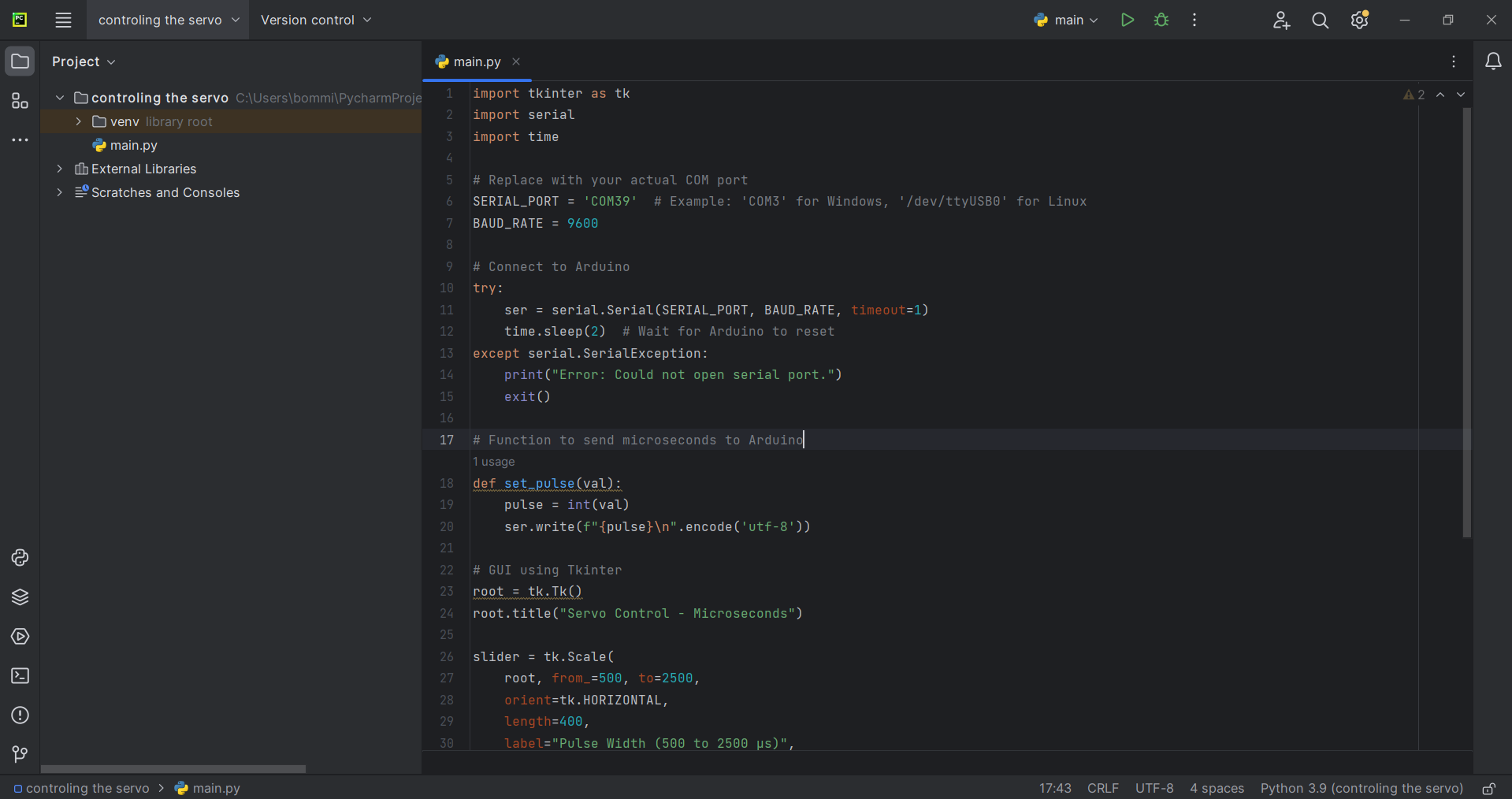
Below, I am showing the result after writing and executing the program in PyCharm.
Below, I am showing how I controlled the servo motor using PyCharm.
Arduino Code for Operating a Servo Motor via PyCharm
#include <Servo.h>

Servo myServo;
int pulseWidth;

void setup() {
  Serial.begin(9600);       // Start Serial at 9600 baud
  myServo.attach(9);        // Attach servo to pin 9
}

void loop() {
  if (Serial.available()) {
    pulseWidth = Serial.parseInt();  // Read pulse width from Serial
    if (pulseWidth >= 500 && pulseWidth <= 2500) {
      myServo.writeMicroseconds(pulseWidth);  // Set servo using microseconds
    }
  }
}
Python Code for Operating a Servo Motor via PyCharm
import tkinter as tk
import serial
import time

# Replace with your actual COM port
SERIAL_PORT = 'COM39'  # Example: 'COM3' for Windows, '/dev/ttyUSB0' for Linux
BAUD_RATE = 9600

# Connect to Arduino
try:
    ser = serial.Serial(SERIAL_PORT, BAUD_RATE, timeout=1)
    time.sleep(2)  # Wait for Arduino to reset
except serial.SerialException:
    print("Error: Could not open serial port.")
    exit()

# Function to send microseconds to Arduino
def set_pulse(val):
    pulse = int(val)
    ser.write(f"{pulse}\n".encode('utf-8'))

# GUI using Tkinter
root = tk.Tk()
root.title("Servo Control - Microseconds")

slider = tk.Scale(
    root, from_=500, to=2500,
    orient=tk.HORIZONTAL,
    length=400,
    label="Pulse Width (500 to 2500 µs)",
    command=set_pulse
)
slider.set(1500)  # Set default at center position
slider.pack(padx=20, pady=20)

root.mainloop()

# Close serial after GUI closes
ser.close()
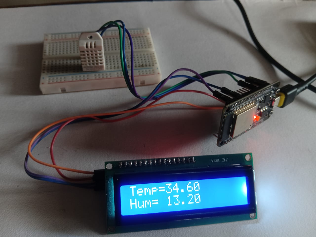
Reading & Displaying Temp/Humidity Data Using ESDP32 :
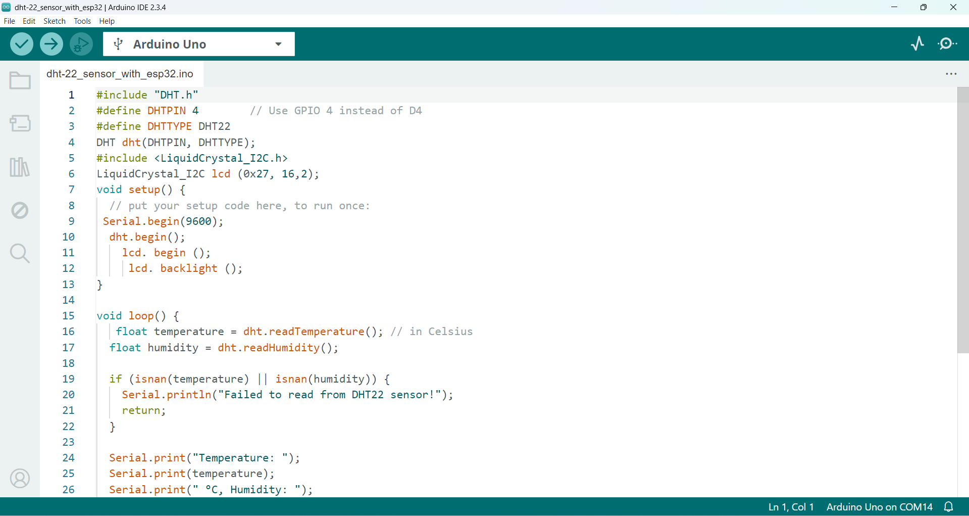
After completing the above steps, I also tested the ESP32 controller. Using the ESP32, I took readings from the DHT22 sensor and displayed the data on the LCD display.
|
|
Arduino Code for Reading & Displaying Temp/Humidity Data Using ESDP32
#include "DHT.h"
#define DHTPIN 4        // Use GPIO 4 instead of D4
#define DHTTYPE DHT22
DHT dht(DHTPIN, DHTTYPE);
#include <LiquidCrystal_I2C.h>
LiquidCrystal_I2C lcd (0x27, 16,2);
void setup() {
  // put your setup code here, to run once:
 Serial.begin(9600);
  dht.begin();
    lcd.begin();
     lcd.backlight();
}

void loop() {
   float temperature = dht.readTemperature(); // in Celsius
  float humidity = dht.readHumidity();

  if (isnan(temperature) || isnan(humidity)) {
    Serial.println("Failed to read from DHT22 sensor!");
    return;
  }

  Serial.print("Temperature: ");
  Serial.print(temperature);
  Serial.print(" °C, Humidity: ");
  Serial.print(humidity);
  Serial.println(" %");
    lcd.setCursor(0, 0);
     lcd.print("Temp=");
     lcd.setCursor(5, 0);
     lcd.print(temperature);
     lcd.setCursor(0, 1);
     lcd.print("Hum=");
     lcd.setCursor(5, 1);
     lcd.print(humidity);
  // put your main code here, to run repeatedly:
delay(1000);
}
Controlling an LED Using Processing on My Custom Development Board
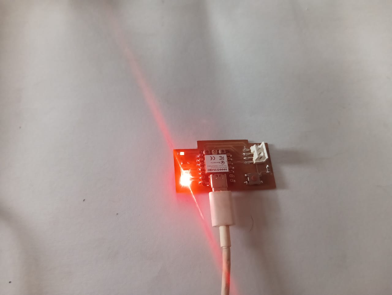
Finally, I decided to control the LED using my own custom-designed board, the ESP32-C3. For this, I used the Processing IDE to control the LED. In the Processing IDE, I created two buttons to turn the LED on and off. The results are shown below.
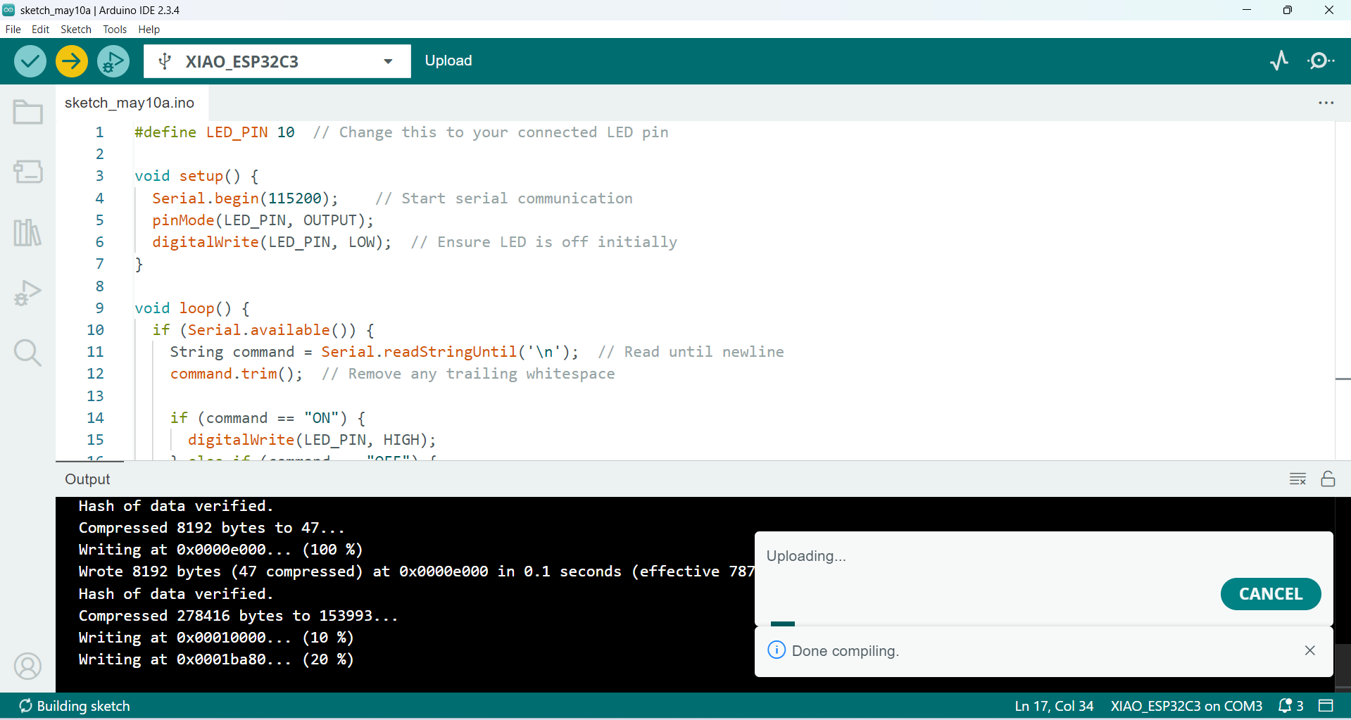
Step 1: I wrote the code in the Arduino IDE. In my case, the LED is connected to GPIO pin number 10. I used serial communication to control the LED, and the code was successfully uploaded to the board.
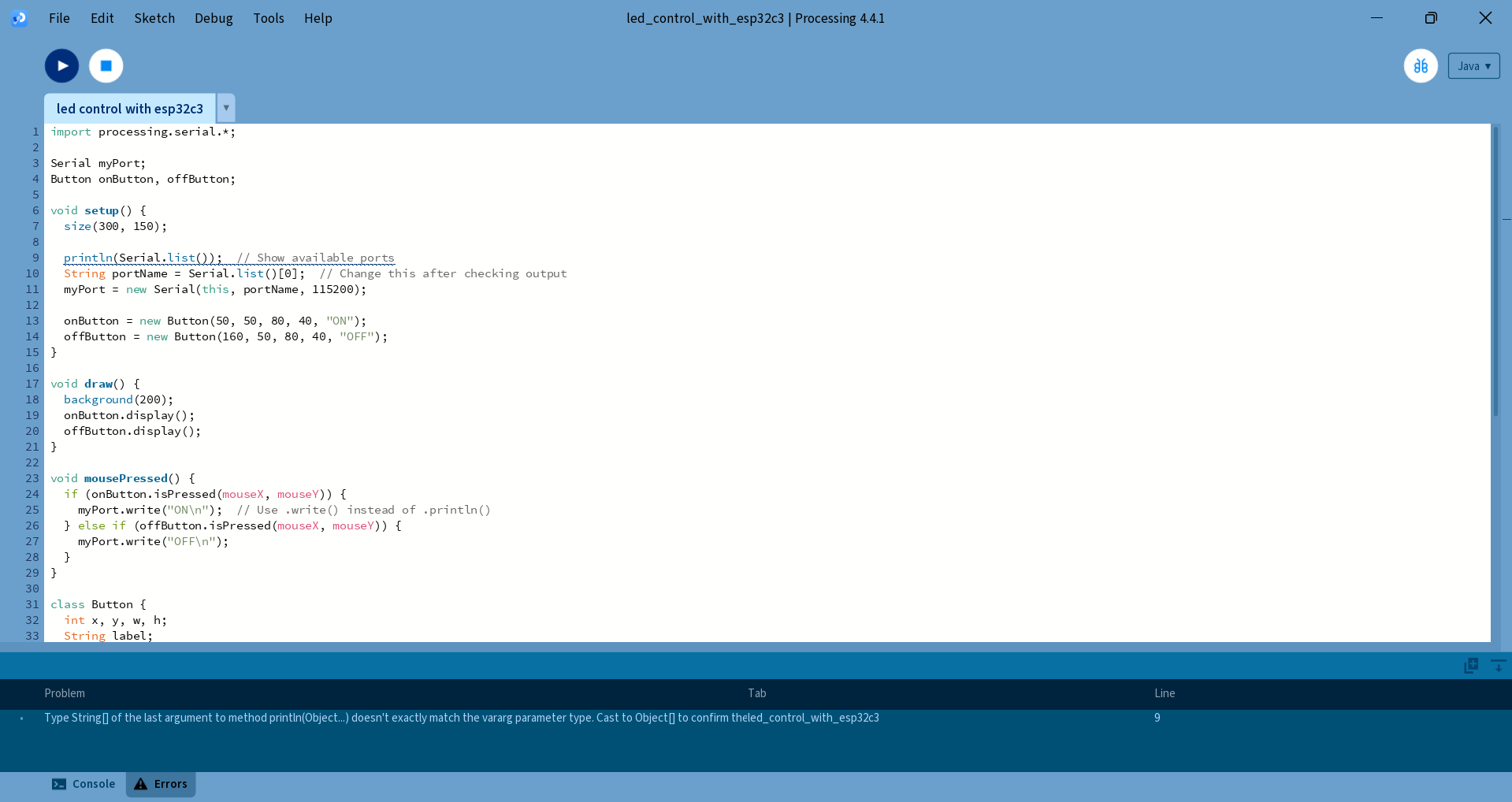
Step 2: After uploading the code to the Arduino, I started writing the code in the Processing software. I created two buttons: one for turning the LED on and the other for turning it off. I wrote the code and ran it successfully. The results are shown in the image below.
|
|
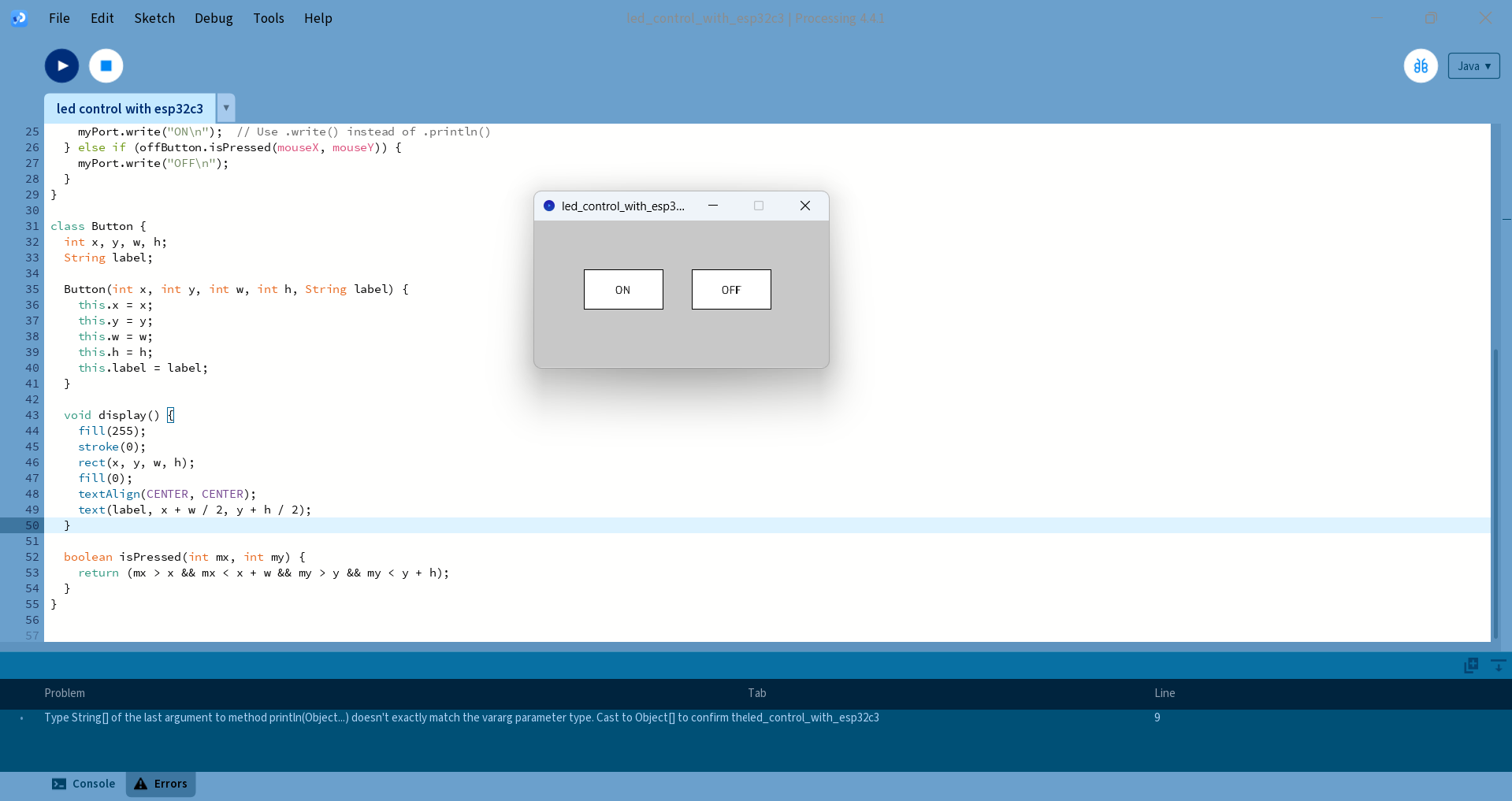
After running the Processing code, a new window opened for controlling the LED with buttons. The LED was successfully turned on and off.
|
|
|
Below, I am showing how I controlled the LED ON and OFF using Processing.
Arduino Code for Controlling an LED Using Processing
#define LED_PIN 10  // Change this to your connected LED pin

void setup() {
  Serial.begin(115200);    // Start serial communication
  pinMode(LED_PIN, OUTPUT);
  digitalWrite(LED_PIN, LOW);  // Ensure LED is off initially
}

void loop() {
  if (Serial.available()) {
    String command = Serial.readStringUntil('\n');  // Read until newline
    command.trim();  // Remove any trailing whitespace

    if (command == "ON") {
      digitalWrite(LED_PIN, HIGH);
    } else if (command == "OFF") {
      digitalWrite(LED_PIN, LOW);
    }
  }
}
Processing code for Controlling an LED Using Processing
import processing.serial.*;

Serial myPort;
Button onButton, offButton;

void setup() {
  size(300, 150);

  println(Serial.list());  // Show available ports
  String portName = Serial.list()[0];  // Change this after checking output
  myPort = new Serial(this, portName, 115200);

  onButton = new Button(50, 50, 80, 40, "ON");
  offButton = new Button(160, 50, 80, 40, "OFF");
}

void draw() {
  background(200);
  onButton.display();
  offButton.display();
}

void mousePressed() {
  if (onButton.isPressed(mouseX, mouseY)) {
    myPort.write("ON\n");  // Use .write() instead of .println()
  } else if (offButton.isPressed(mouseX, mouseY)) {
    myPort.write("OFF\n");
  }
}

class Button {
  int x, y, w, h;
  String label;

  Button(int x, int y, int w, int h, String label) {
    this.x = x;
    this.y = y;
    this.w = w;
    this.h = h;
    this.label = label;
  }

  void display() {
    fill(255);
    stroke(0);
    rect(x, y, w, h);
    fill(0);
    textAlign(CENTER, CENTER);
    text(label, x + w / 2, y + h / 2);
  }

  boolean isPressed(int mx, int my) {
    return (mx > x && mx < x + w && my > y && my < y + h);
  }
}
Simulation in Tinkercad :
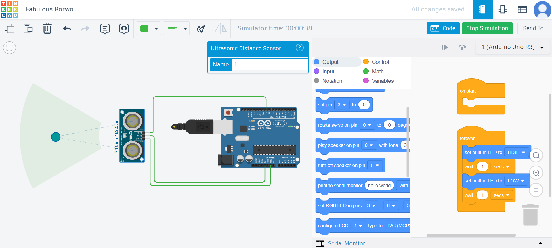
After completing the hands-on work, I realized that this assignment also includes simulation. So, I started the simulation using Tinkercad. Tinkercad is an open-source platform that allows electronic circuit simulation. I used it to simulate an ultrasonic sensor, and below I am showing how I did it.
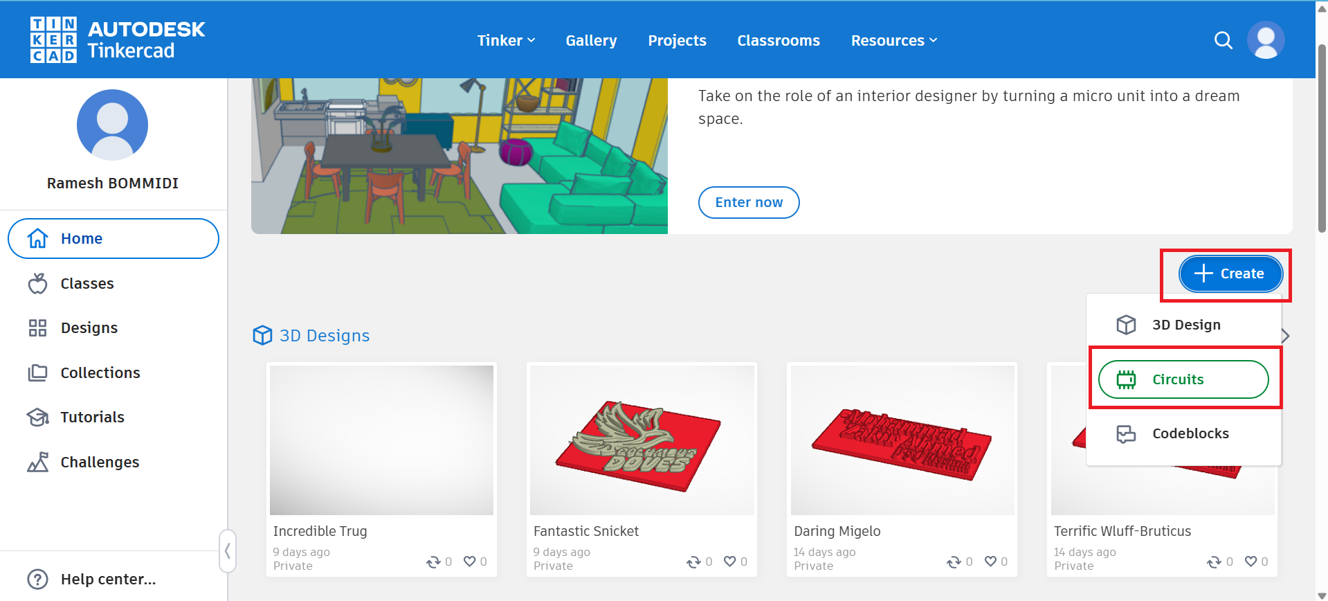
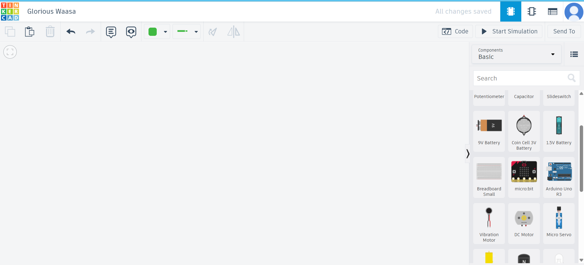
Step 1: I opened Tinkercad and logged in using my Google account. Then, I started creating the circuit design. The image below shows this step. Click here for Tinkercad
|
|
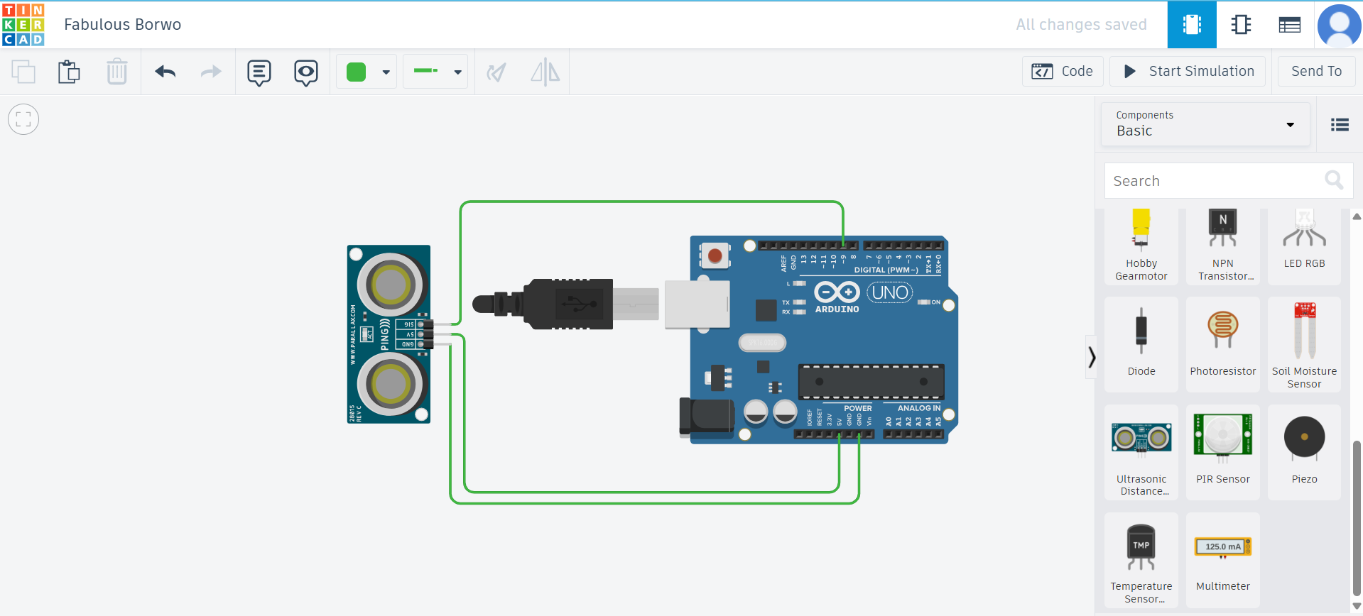
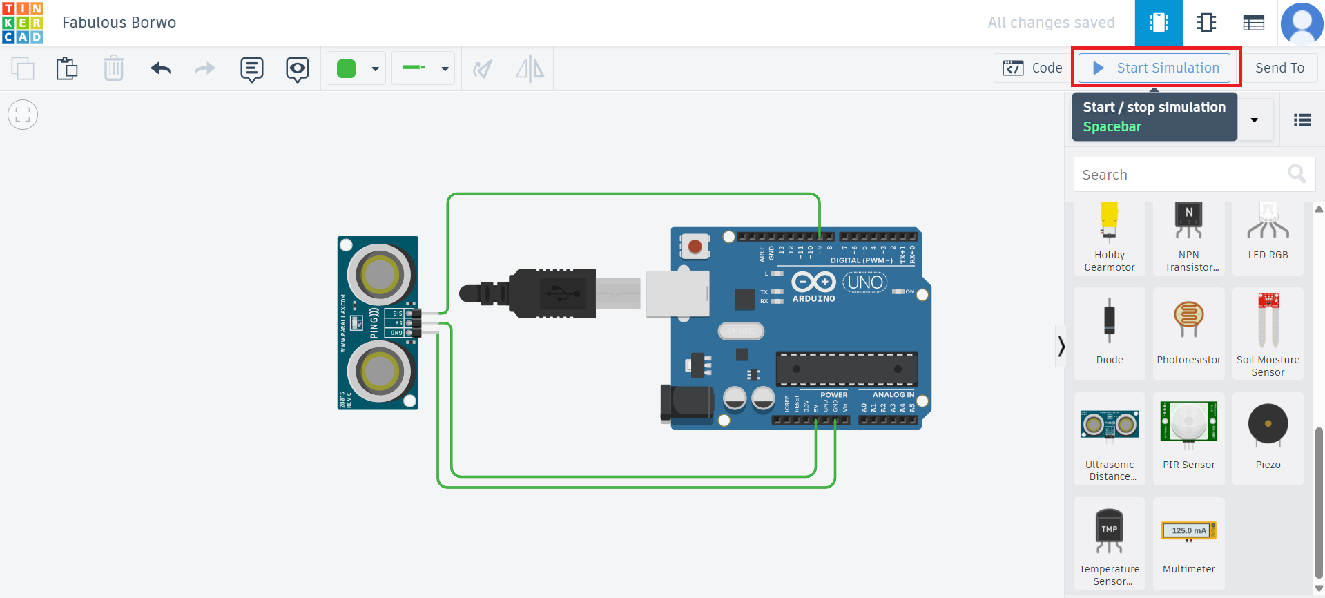
Step 2: After that, I connected the ultrasonic sensor to the Arduino and then started the simulation.
|
|
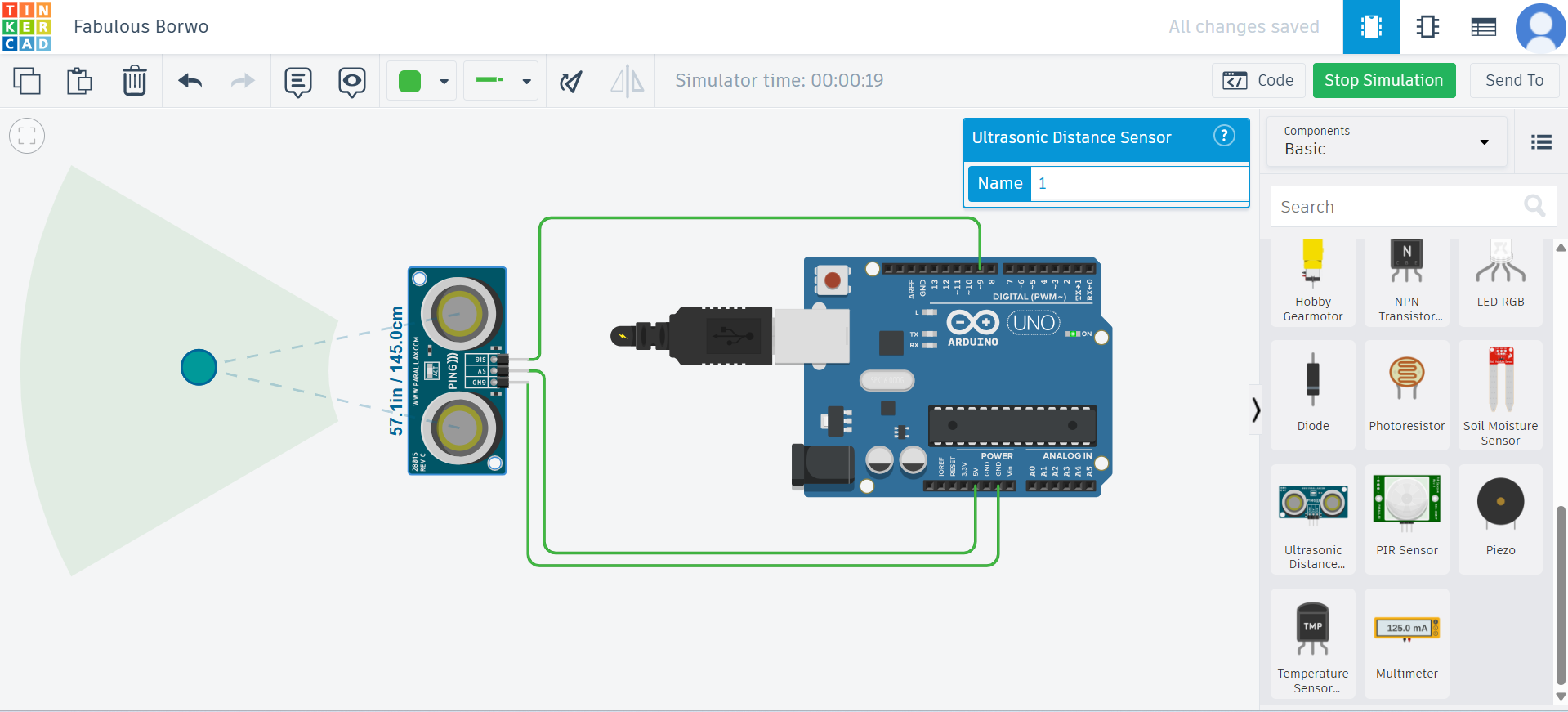
Below, I am showing the simulation results.
|
|
Positive Outcomes:
This week, I explored how to write code for controlling different components by reading datasheets for controllers. I controlled LEDs in various ways, and I literally enjoyed the process of learning new things. Writing the first code to make the LED turn on was a moment of excitement. This assignment helped me explore new possibilities and enhance my skills, which I have included in this assignment.
Challenges Encountered:
This week, I had a smooth experience while working with the ATmega328P and ESP32-WROOM modules. The process of reading the datasheets was straightforward, and I was able to understand the specifications clearly. Integrating the components such as LEDs, sensors, and motors was also successful, and I didn’t encounter any major issues with the hardware or software. The various tasks, including using Arduino IDE and Processing, went smoothly, and I was able to complete everything as planned without any difficulties.