Assignment 12: Mechanical Design, Machine Design
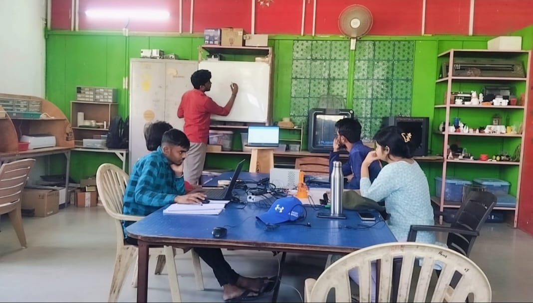
This assignment focuses on my learning outcomes from the Mechanical Design and Machine Design week. It covers both the collaborative efforts of our group and my individual contributions toward building a functional machine. Although the tasks were distributed among team members based on different processes, we followed a concurrent and collaborative working method to complete the project efficiently. This documentation outlines our initial concept, the brainstorming sessions, and the structured workflow we adopted throughout the design and construction phases of the machine. A detailed account of my personal involvement and responsibilities in the project is also provided.
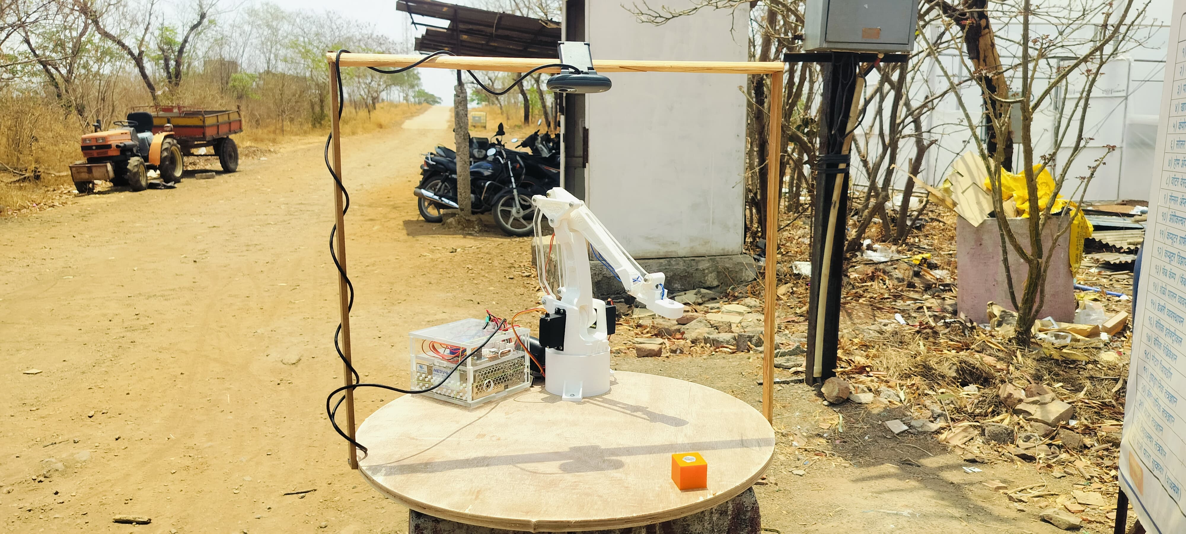
Name of our Machine is 'OphthalMekha'. It is a Greek word, which in English means a 'Eye Machine'. In Greek(ὀφθαλμός–μηχανή).
My Role in Completing this Assignment:
- I was primarily responsible for the programming of the machine, which I worked on along with Fenil. This included:
1.Writing and testing code in Python using OpenCV for image processing.
2. Developing control logic in C++ to operate the machine.
- I created several tabulations and logs during the machine's operation and prototype testing to analyze performance and troubleshoot issues.
- Apart from programming, I was also involved in:
1. Fabrication tasks such as laser cutting, 3D printing, and cutting and grinding of machine parts.
2. Assisting in the electronics section, especially focusing on the hardware setup and connections.
- I took the lead in compiling and editing the group assignment documentation to ensure all team efforts were clearly and accurately represented.
Highlight Moments of the Week
Final Presentation Video
Group Assignment Brief:
Objective of the Group Assignment
- design a machine that includes mechanism+actuation+automation+application
- build the mechanical parts and operate it manually
- document the group project and your individual contribution
To learn more about our machine OphthalMekha and explore the complete group work process, please visit our project website.,
In the section below, I explain how we started working on the machine and how we completed it step by step.
My team and I, along with the support of our mentor, finalized the idea of building OphthalMekha for the Machine Week project. However, the main challenge we faced was that we were unsure how the machine would function after programming. To address this, we decided to build a small-scale prototype of our machine. We tested the concept in a ready-made design approach — downloading, 3D printing, and assembling all necessary parts. Once assembled, we began programming the machine. Below, we explain the complete process of how we built it, how the programming was done, and how the machine functions.
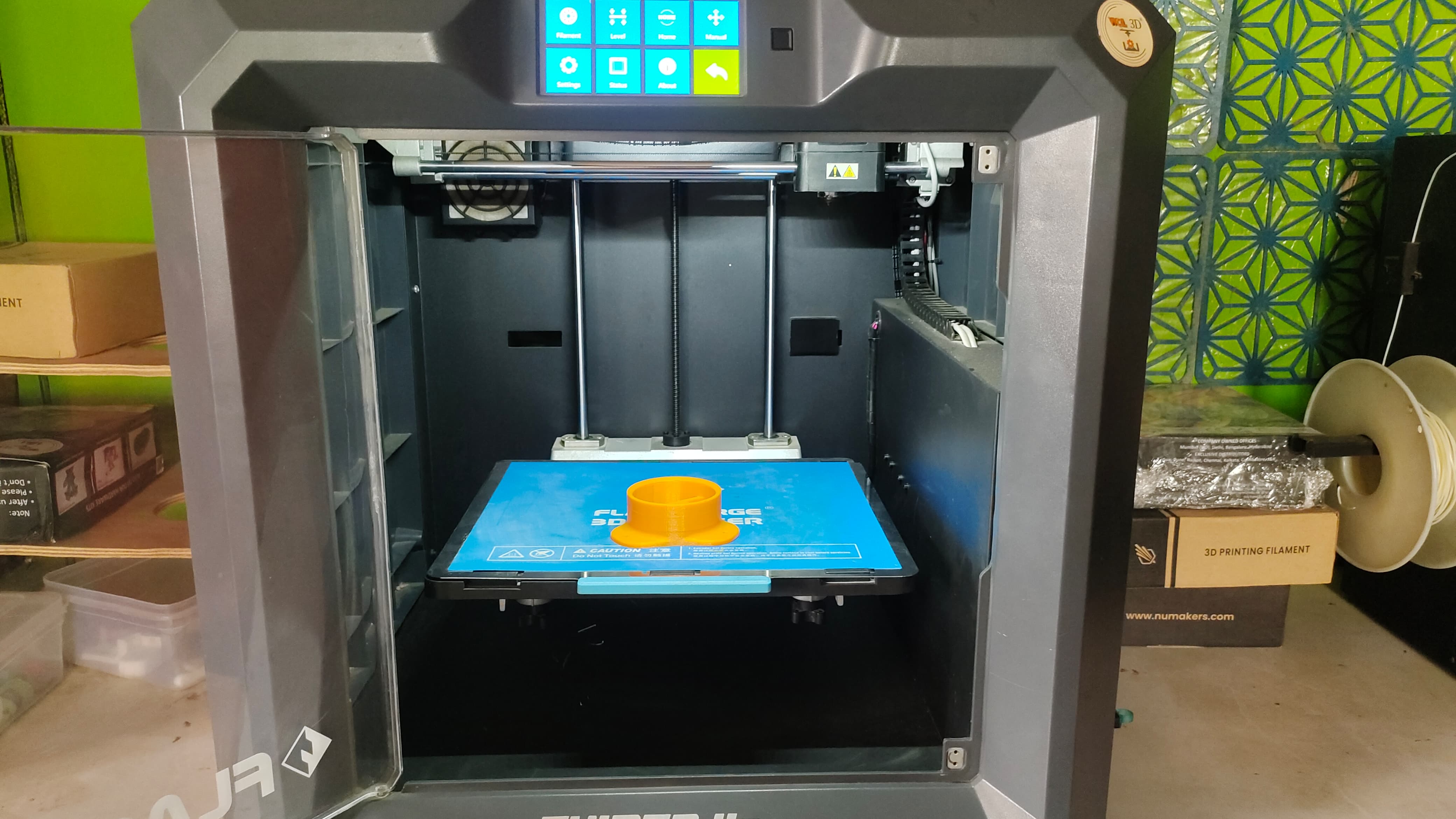
Step 1:We started by 3D printing all the necessary parts for the machine. Below, I have included images showing the printing process and the printed components.
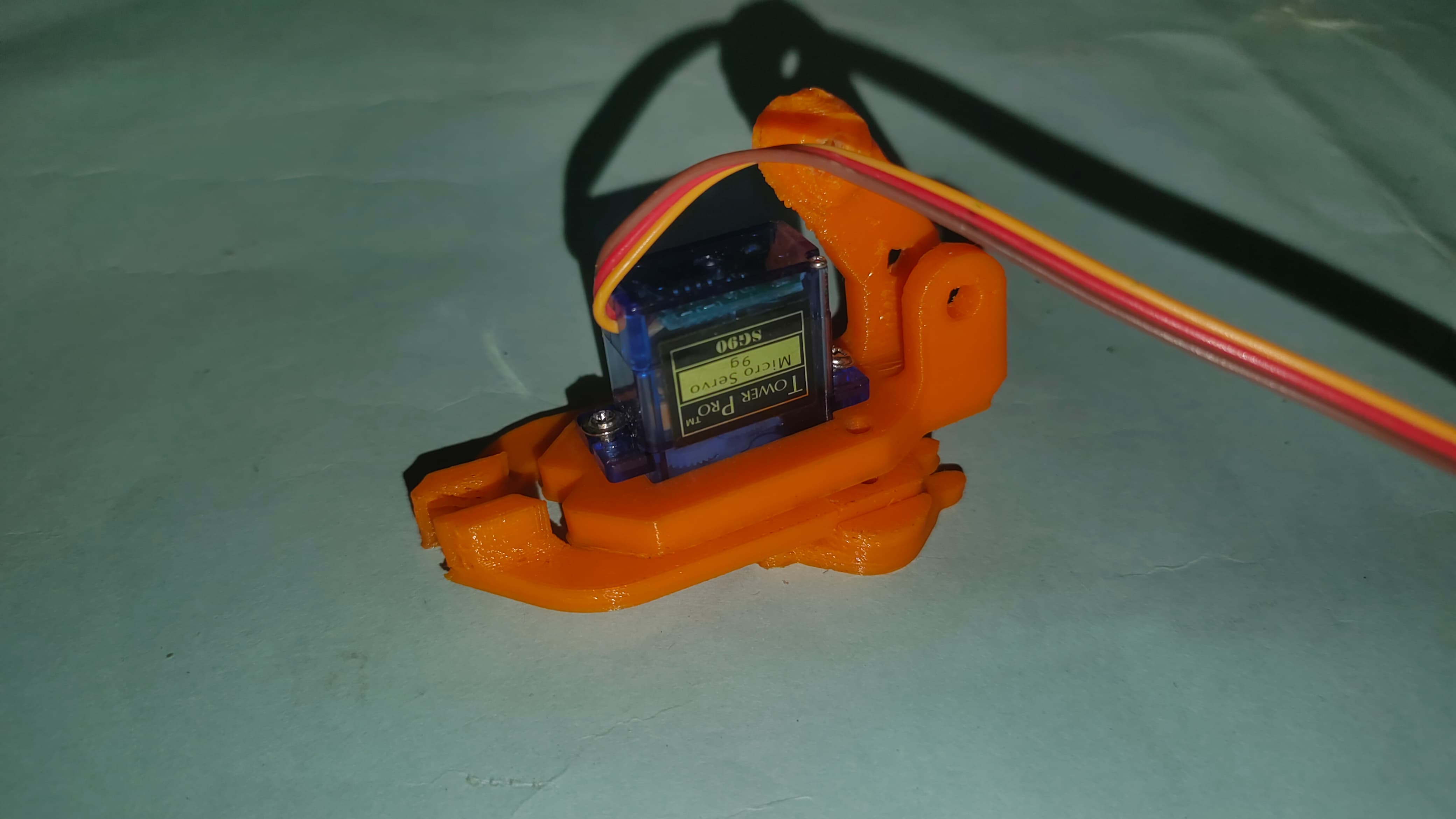
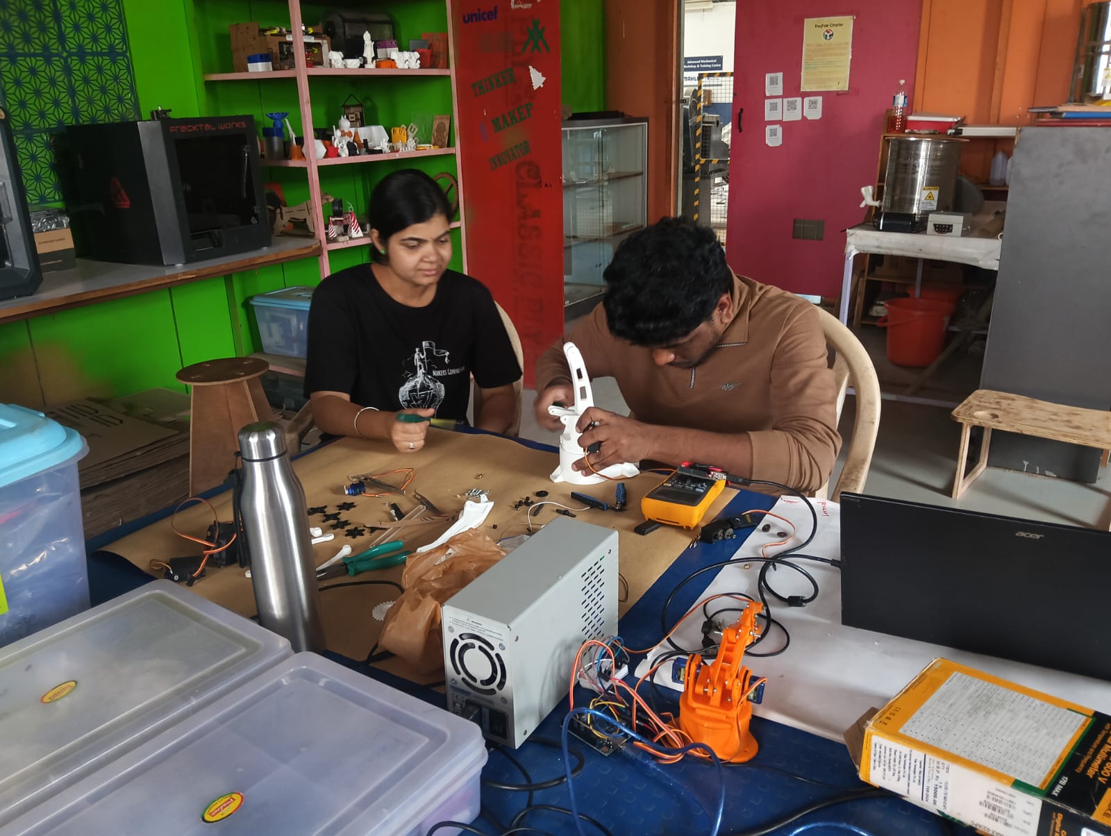
Step 2: After all the printed parts were ready and received, we began the assembly process step by step. We started with assembling the base and began by testing whether the servo motor was functioning correctly. After confirming that the servo was working, we fixed the plate on it and checked whether it could rotate smoothly.
- Below, I am showing the results of these initial assembly and testing steps.
Step 3: After completing the base servo assembly, we proceeded to attach the main structural arms of the robot — the shoulder arm, responsible for forward and backward motion, and the elbow arm, which handles vertical lifting.Below, we are showing how we fixed both arms during the assembly process.
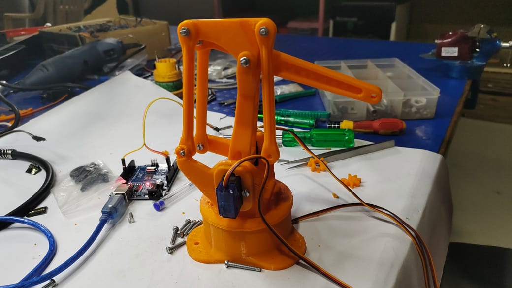
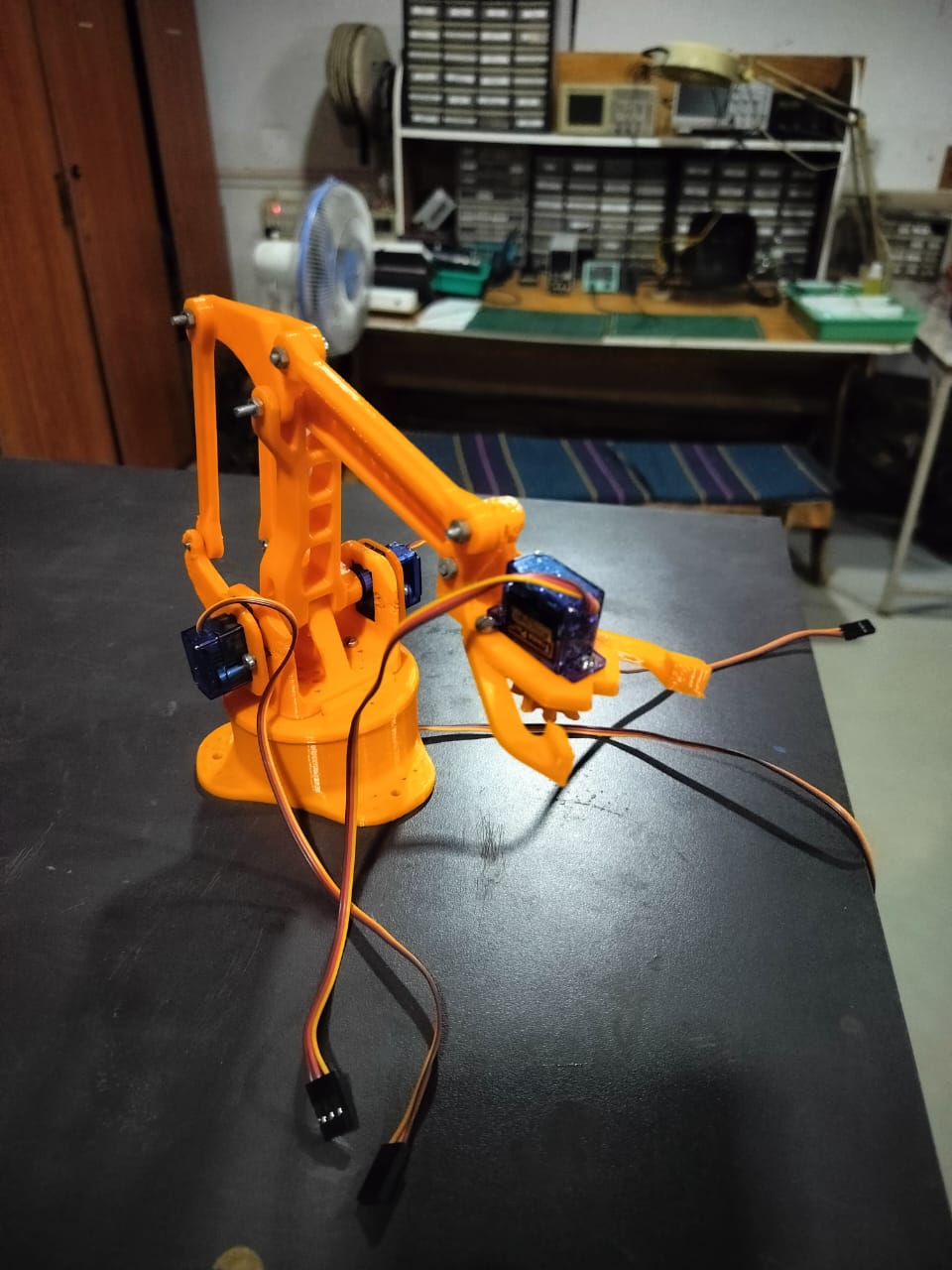
Step 4: After completing the assembly of the two main arms, we attached the end-effector to the robotic arm. The image below shows how the end-effector was fixed in place.
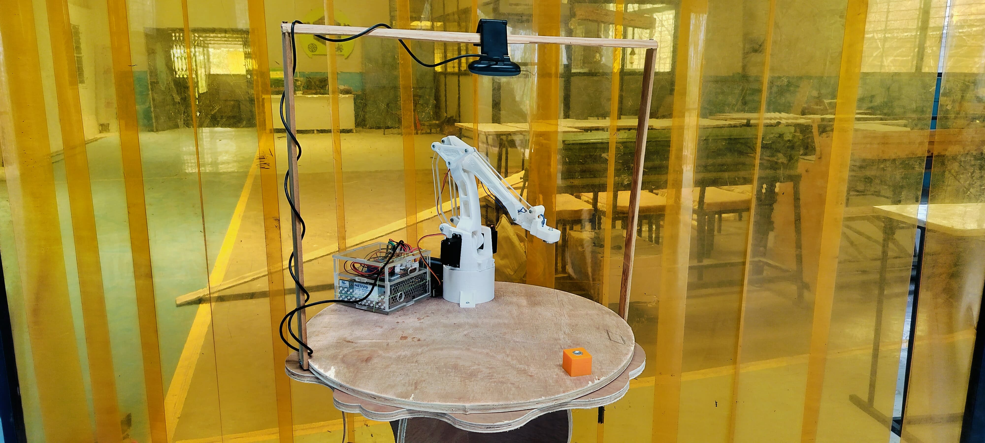
Final Assembly: The complete assembly of my prototype is shown below.
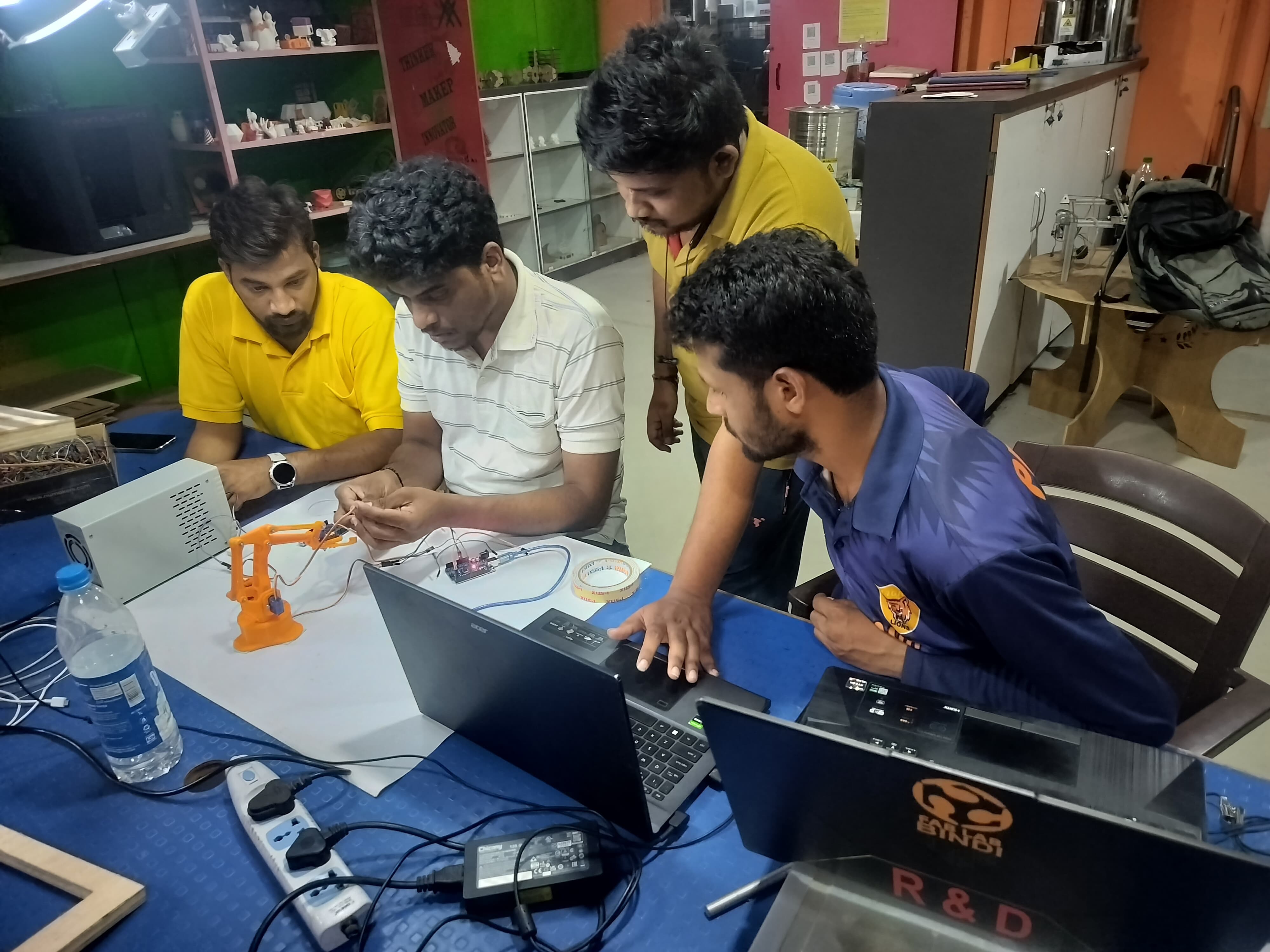
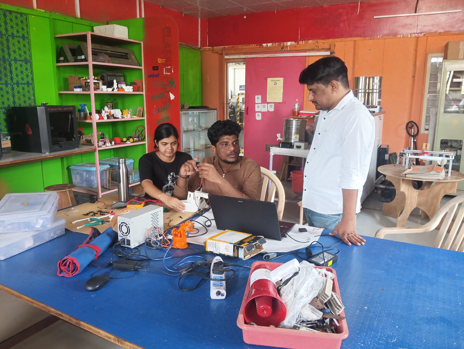
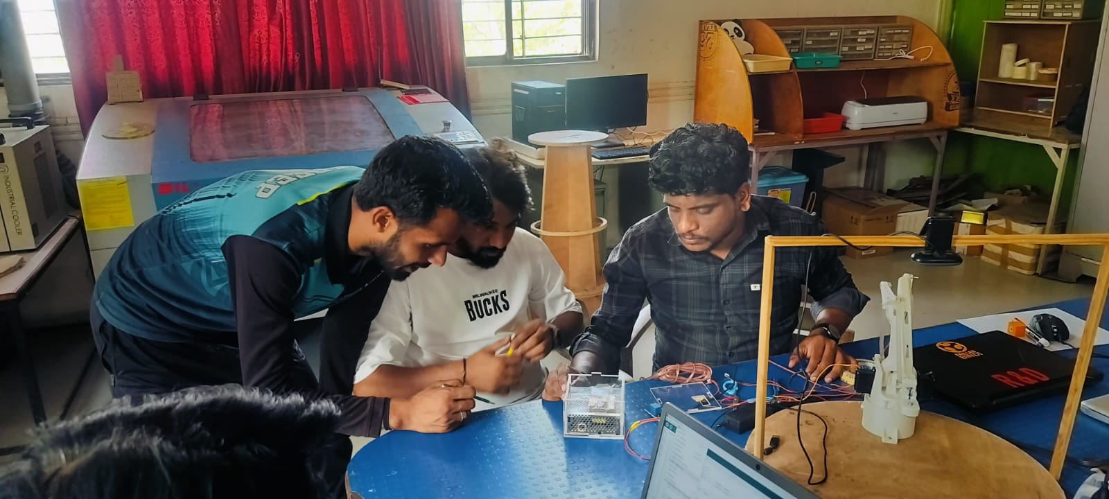
Step 5: After completing the full assembly, we began working on the coding part. For testing purposes, we used two Arduino UNO boards, which were connected using wired communication.
This setup was necessary because we were sending data from Python to Arduino via serial communication, and it’s not possible to view incoming data on the Arduino Serial Monitor while Python is actively communicating.
So, to verify and monitor the data being sent, we connected two Arduinos via wired communication — this made our testing process smoother and more efficient.
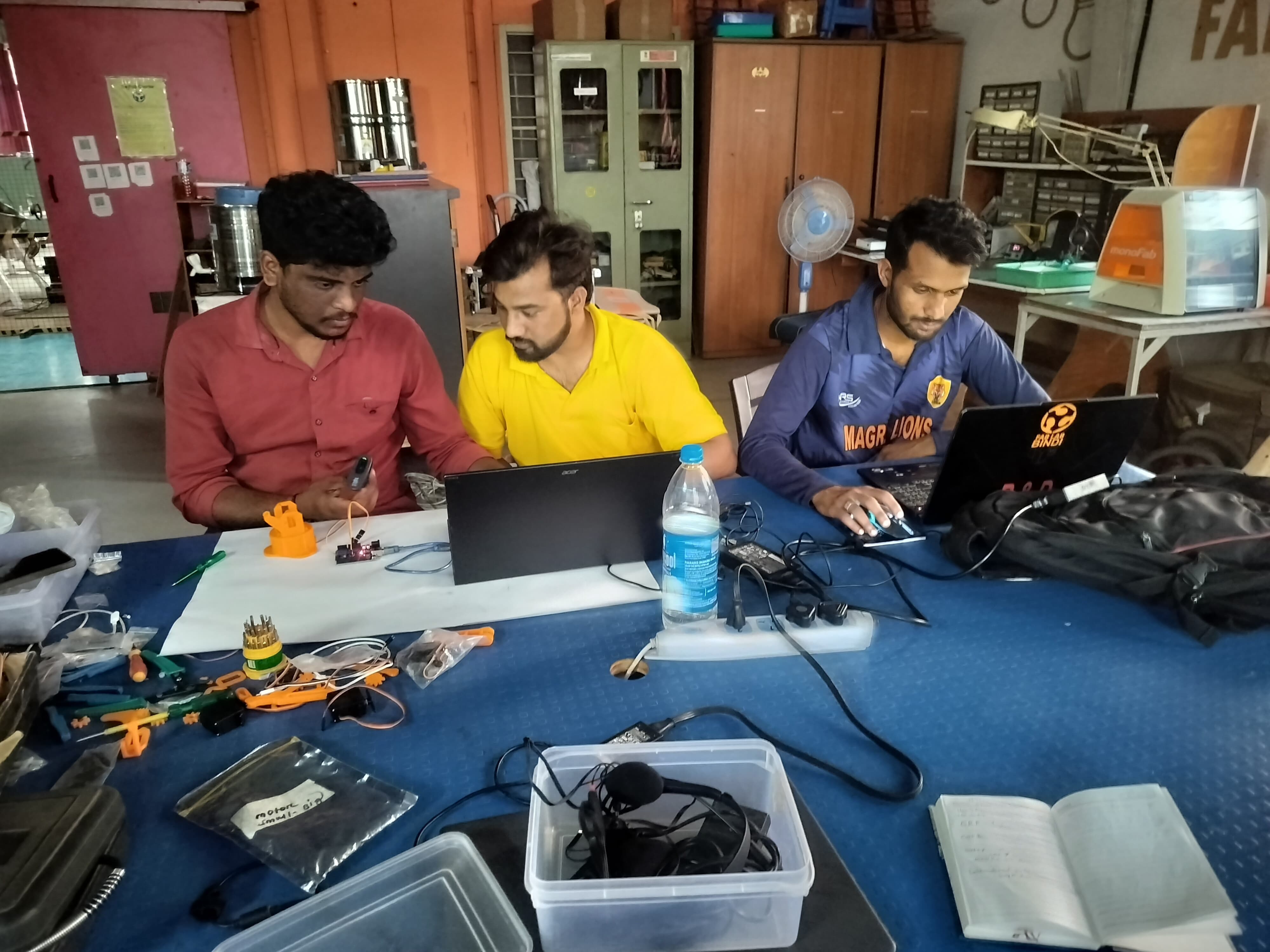
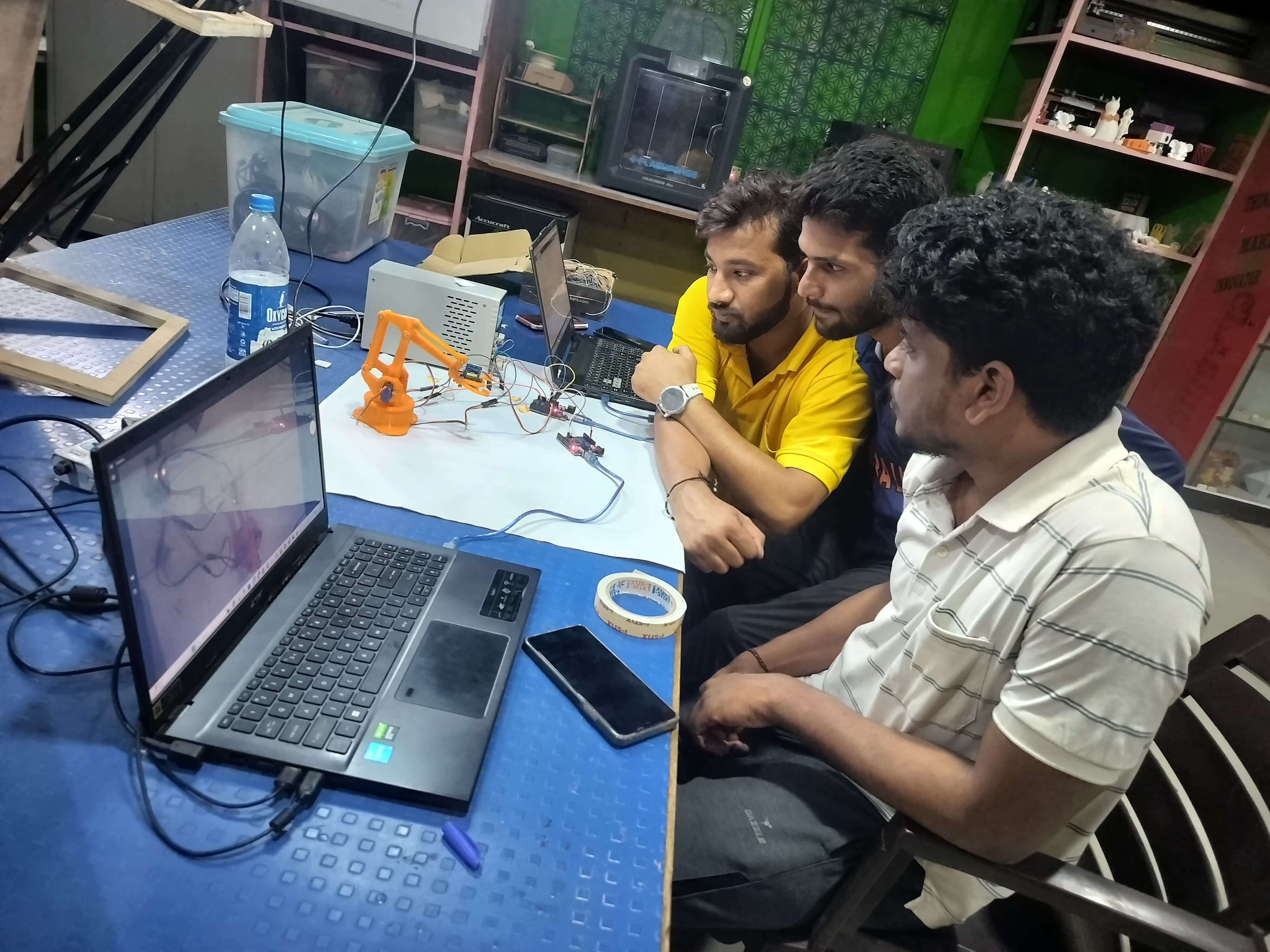
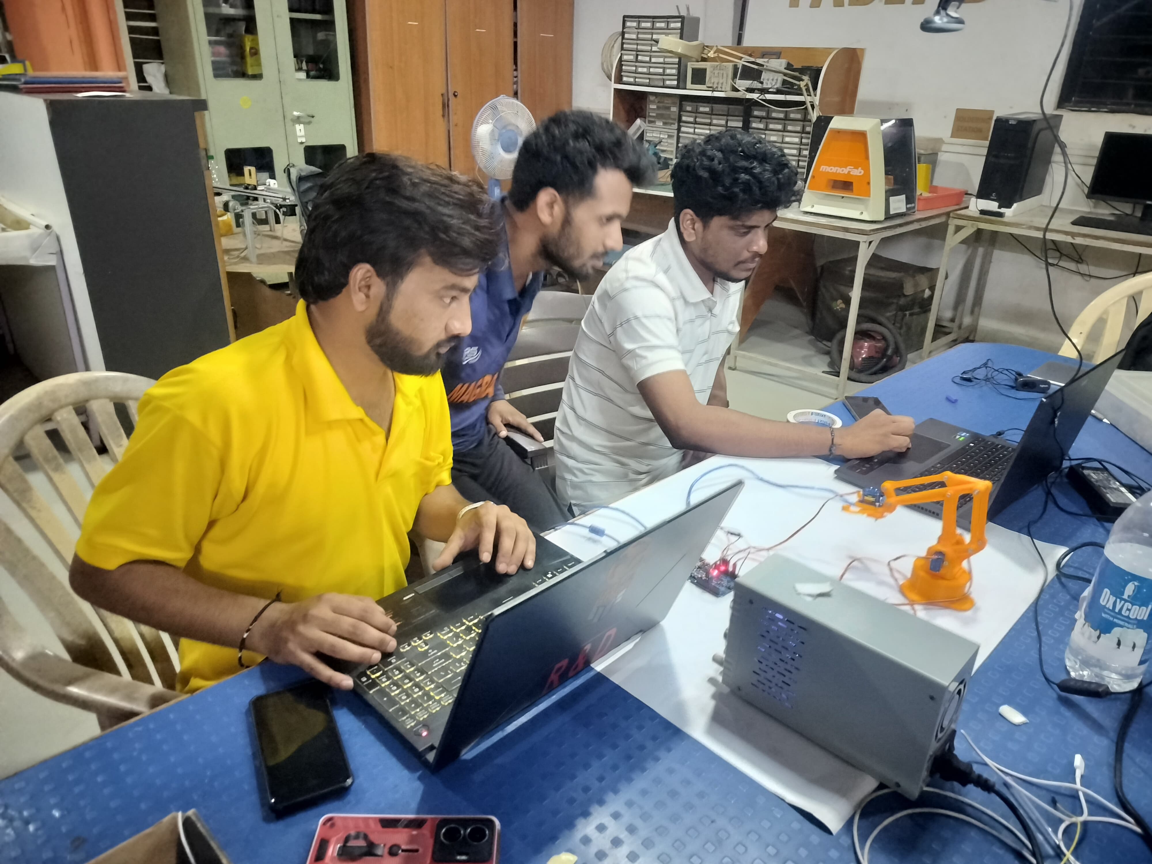
Below, I am showing how the two Arduinos were connected to two separate laptops for data exchange and monitoring.We were able to observe and verify the data transmission between Python and Arduino through this setup.
Step 6: We connected a webcam and started writing the object detection code using PyCharm. The program detects the object and calculates the required servo angles based on its coordinates.
These calculated angles are then sent to the second Arduino via wired communication, and we observed the received angles from the second system to ensure everything was working correctly.
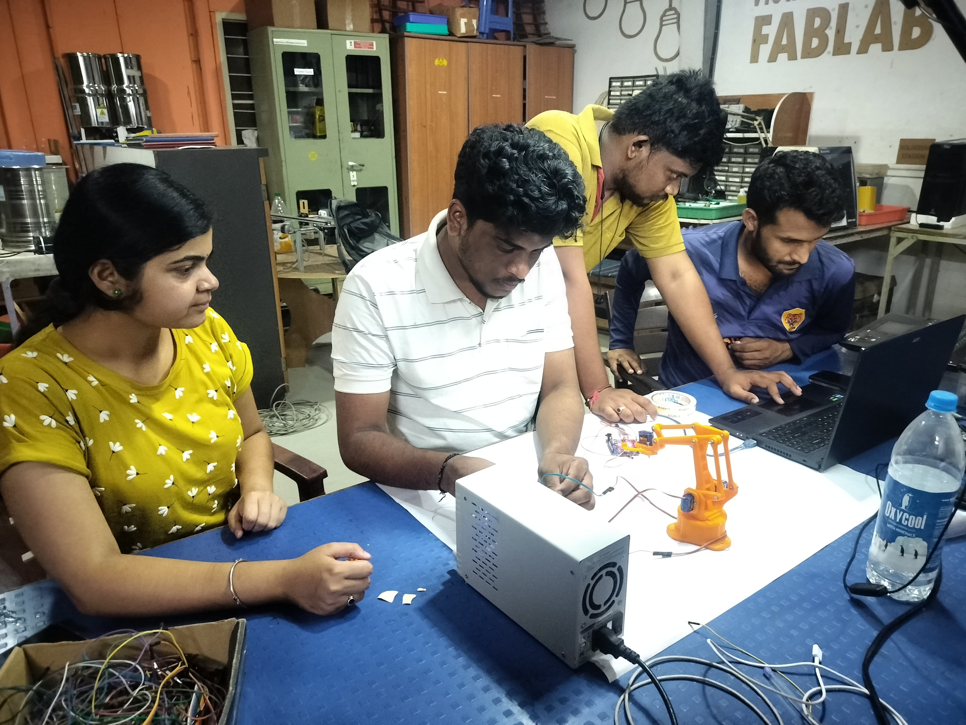
Step 7: After confirming the servo angles through testing, we removed the second system and started writing the final Arduino program to control the servo motors. For this, we used the Servo.h library to operate the servos effectively. The second Arduino was then directly connected to a power supply, allowing it to run the servos independently based on the received commands.
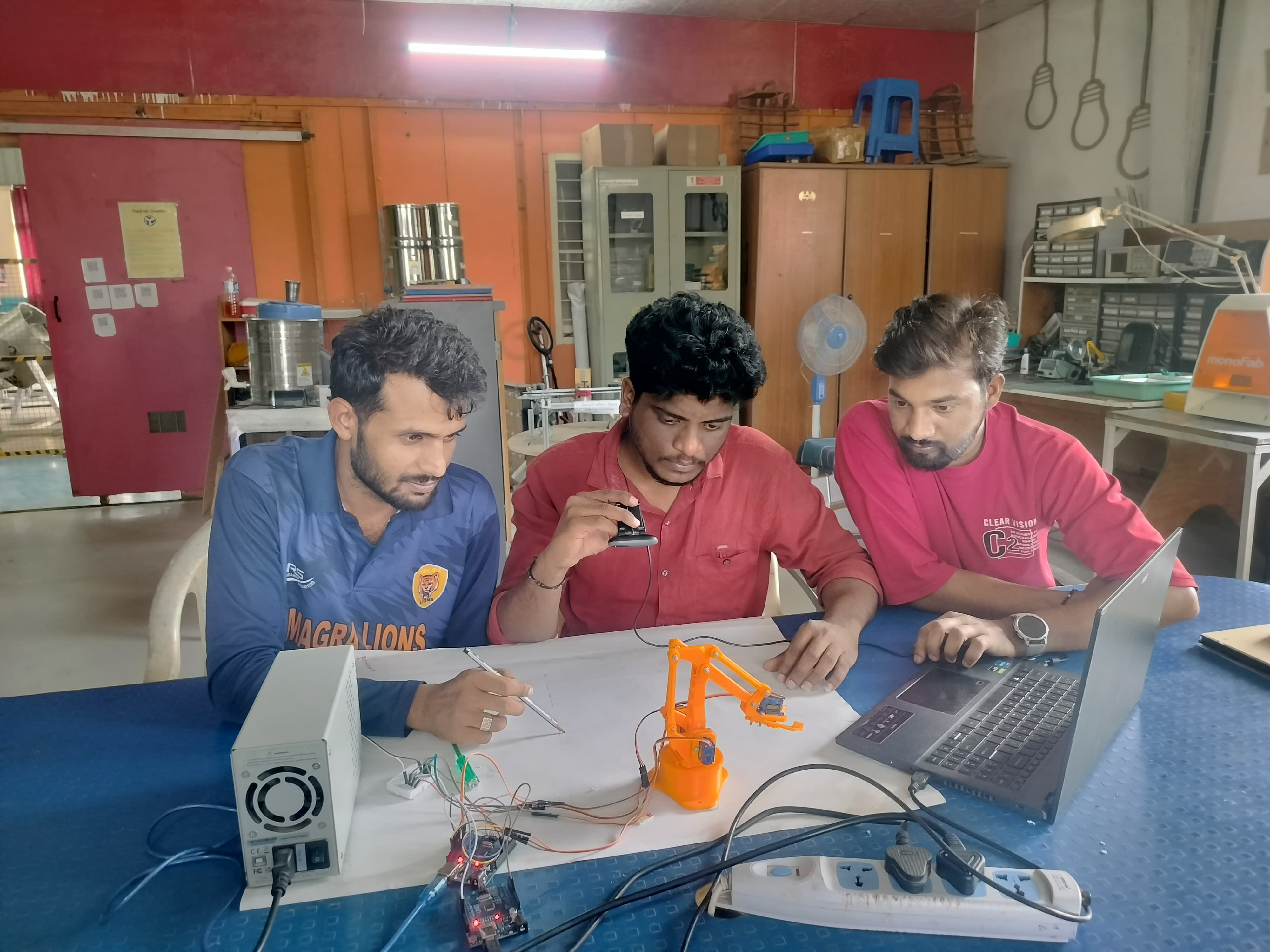
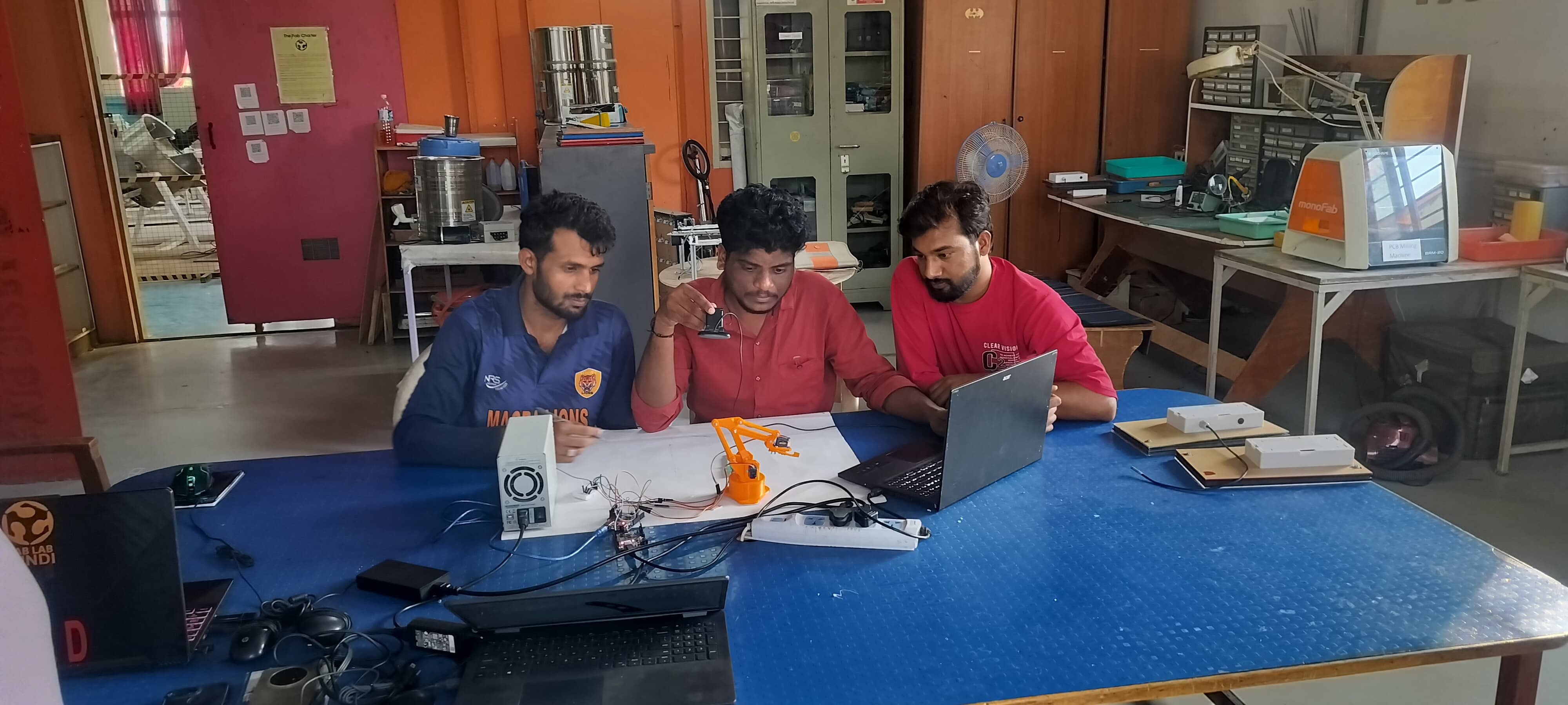
Below, we are showing the first successful working of our prototype using object detection.
We were all very excited to see our machine in action for the first time!
After seeing the initial working of our prototype, we observed and discussed several areas for improvement.
The most prominent issue was that the servo motors were moving too fast, causing the arm movements to be jerky. To solve this, we used the VarSpeedServo.h library in the Arduino code for smoother operation.
Another challenge was with the Python-based object detection, which was frequently detecting unrelated objects, causing inaccuracies in the robotic arm's movements. We addressed this by refining the object detection logic and applying better filtering techniques.
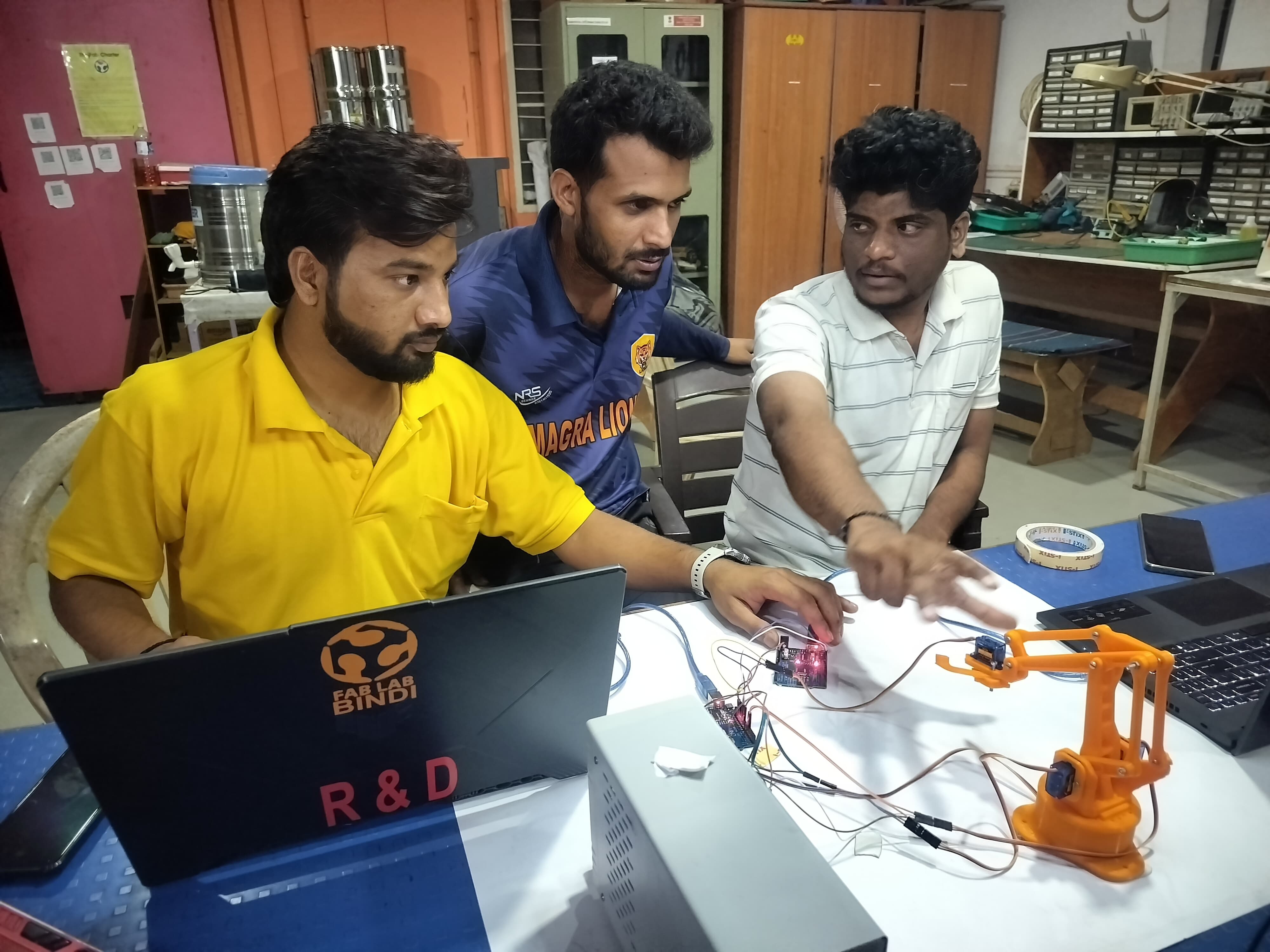
After multiple trials, code modifications, and debugging sessions, we successfully achieved a smooth, stable, and accurate working prototype.
Below is the final working video of our prototype. It was truly exciting and satisfying to see the machine perform as expected after all the effort.
Concept:
Once we completed the prototype testing successfully, we began discussing the overall concept of our machine. We focused on finalizing the design approach, selecting appropriate materials for different components, and identifying the types of motors required for smooth and efficient operation. This planning phase was crucial to ensure our machine would function reliably and meet the intended objectives.
The idea behind the robot is based on OpenCV image processing, which is widely used for industrial purposes. This technology enables precise object detection and control, making the robot highly efficient. It is easy to operate, requiring minimal human intervention. By automating tasks, the robot significantly reduces manpower costs. Overall, it enhances productivity and streamlines operations in industrial environments.
We also explored: Reference1,Reference2,Reference3
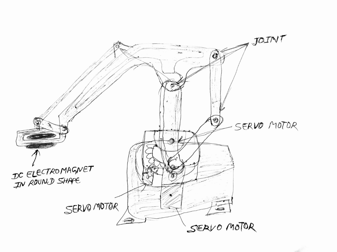
Robot Design and Structure Sketch:
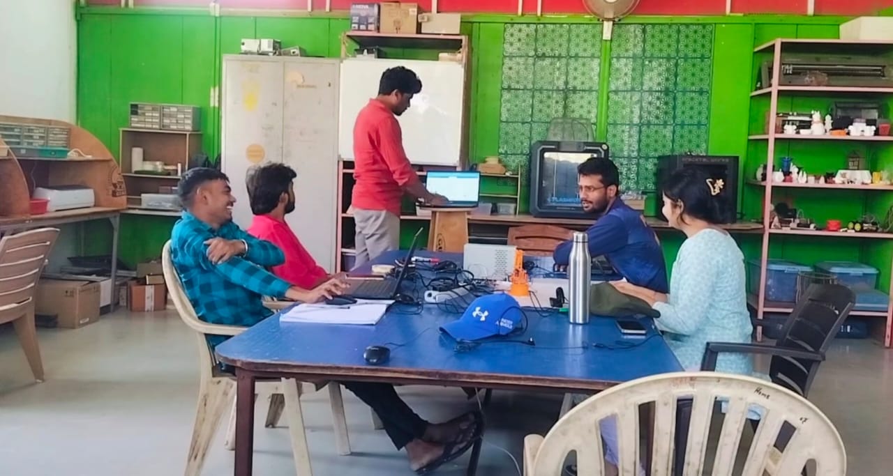
Our team collaboratively explored various design concepts, experimenting with different motor types and end-effector configurations. We evaluated each design's feasibility and performance to identify the most effective solution. Through this iterative process, we refined our approach to meet the project's objectives efficiently.
Workflow Overview:
We divided the tasks among team members to construct the machine
1. Shivraj Singh:Responsible for designing the microcontroller and electronics, as well as compiling the final project video.
2. Pradeep KumarTasked with designing the robotic arm and base mechanism, ensuring structural integrity and functionality.
3. Bommidi Ramesh: Handled the programming aspects of the project and contributed to certain design elements.
Our team worked together by dividing the project into smaller tasks, with each member taking responsibility for specific parts. This clear division of work helped us stay organized and ensured that everyone knew what they needed to do. By communicating regularly and supporting each other, we were able to complete the project efficiently and effectively.
Designing Part:
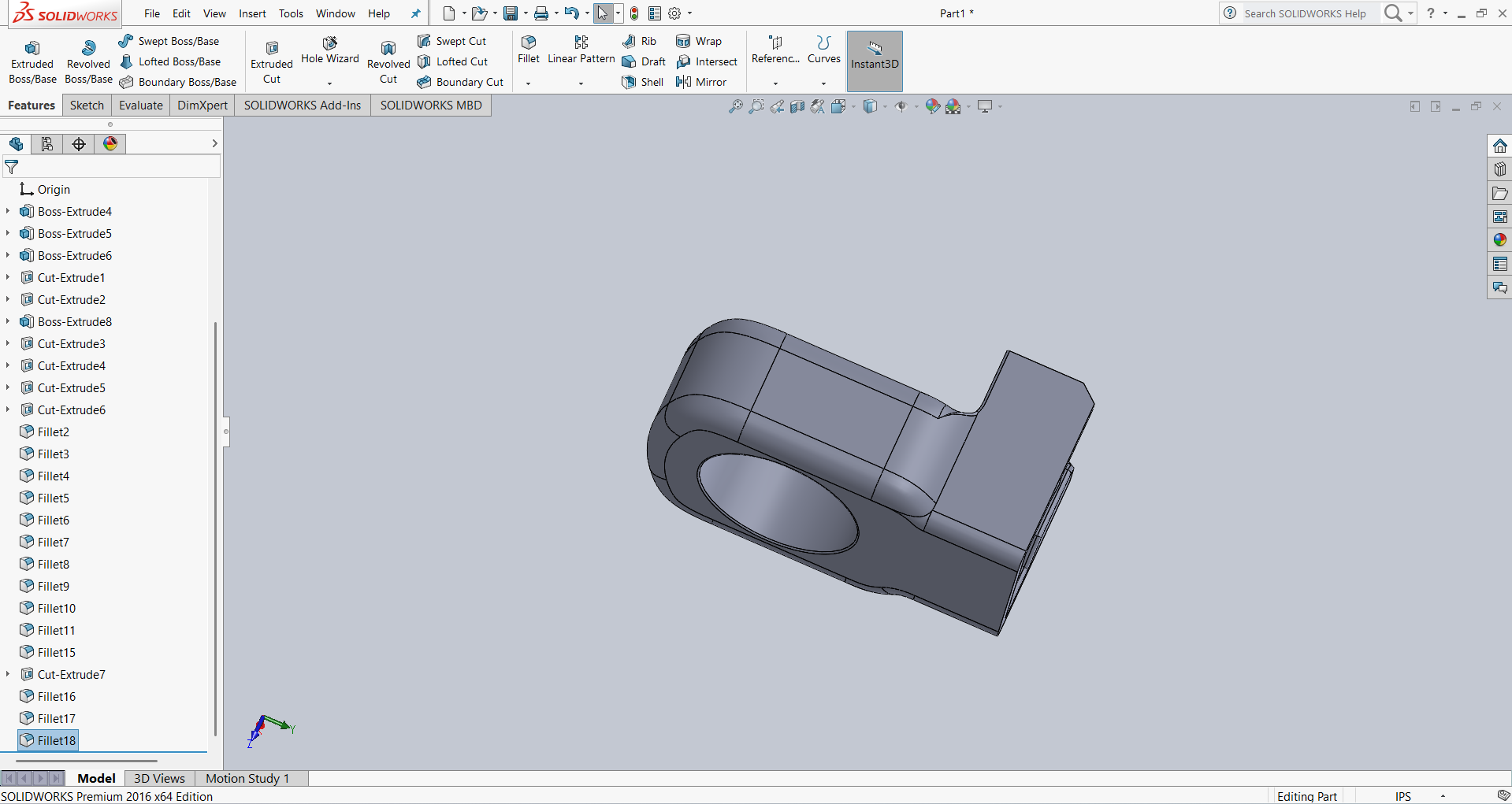
We meticulously designed various components of our robotic arm to ensure optimal functionality and performance. Some parts were modeled using Fusion 360, while others were created in SolidWorks, allowing us to leverage the strengths of both CAD platforms. By accurately measuring the servo motor dimensions, we tailored the designs to ensure proper fit and alignment. Additionally, we made modifications to the end effector, linkages, and arms to enhance the arm's capabilities and adaptability for our specific tasks.
- Below are the design links for my machine.Pradeep took the lead role in the design process, while I contributed by designing some parts using SolidWorks.
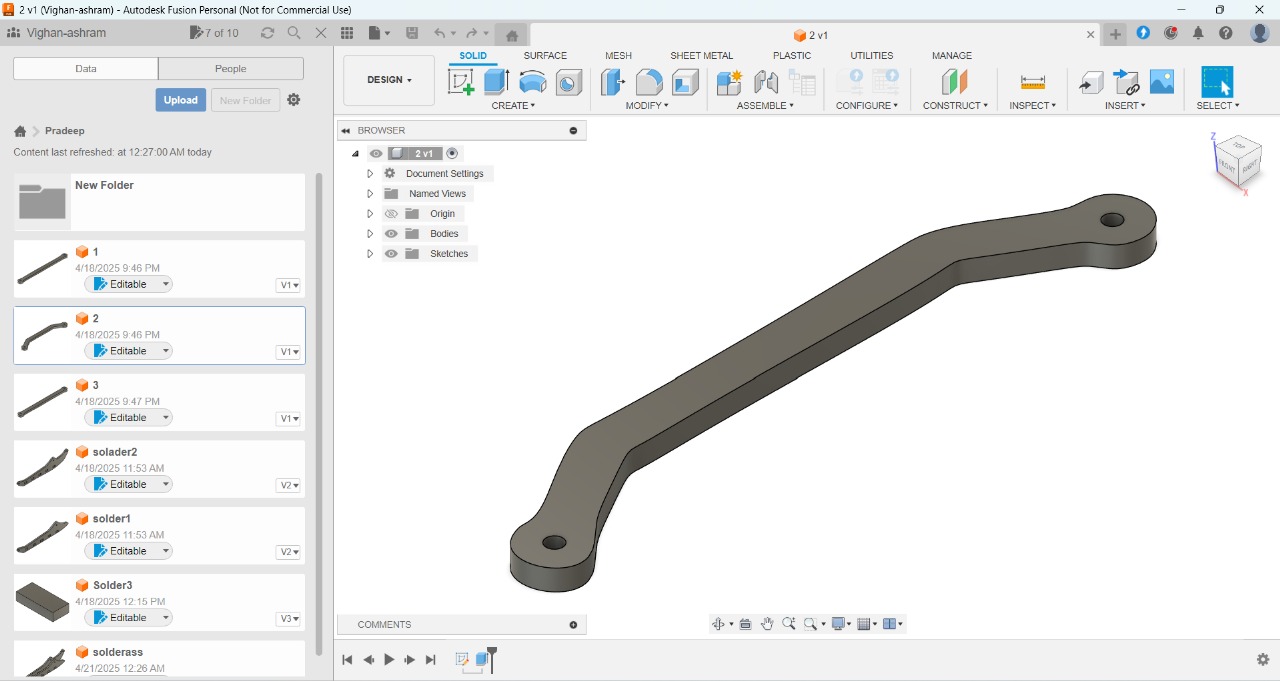
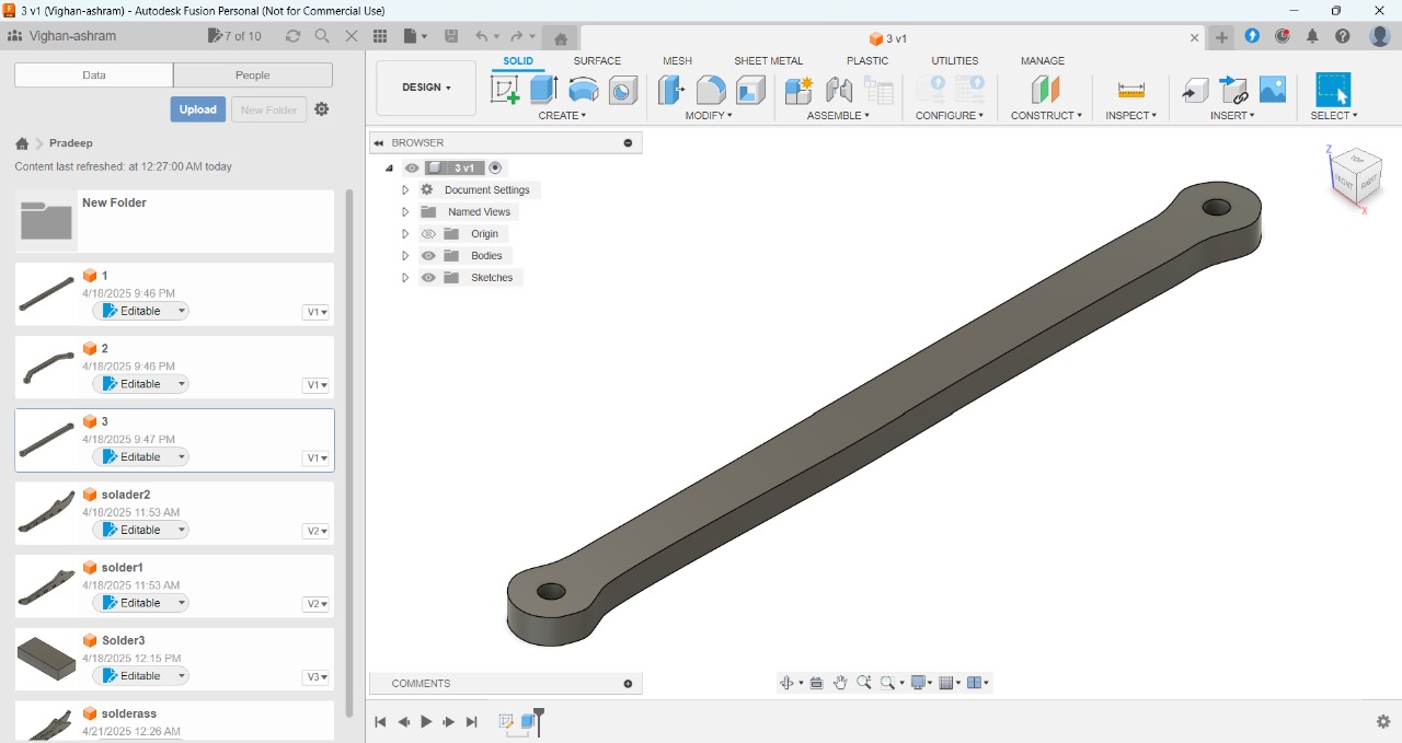
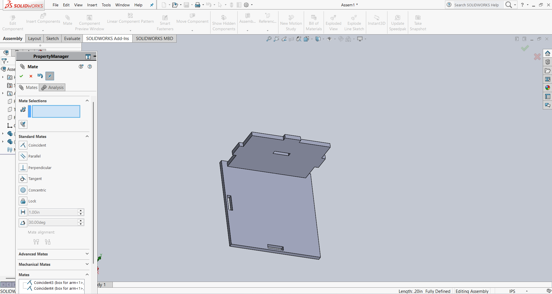
- Below is the main arm of your robotic arm
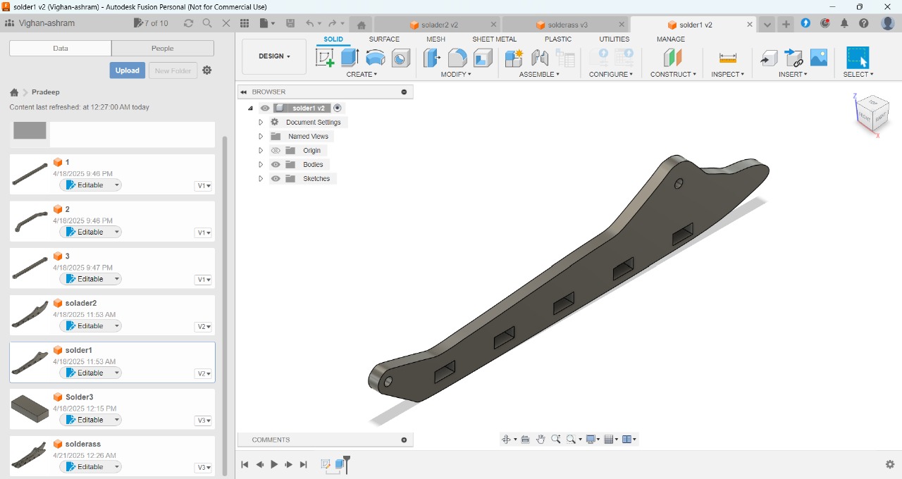
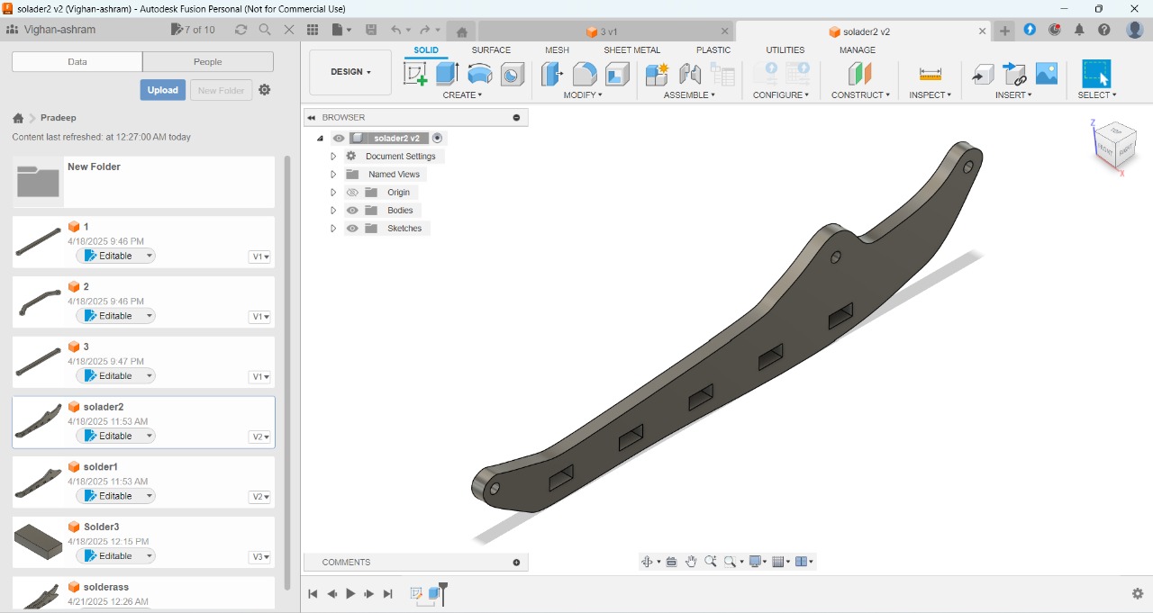
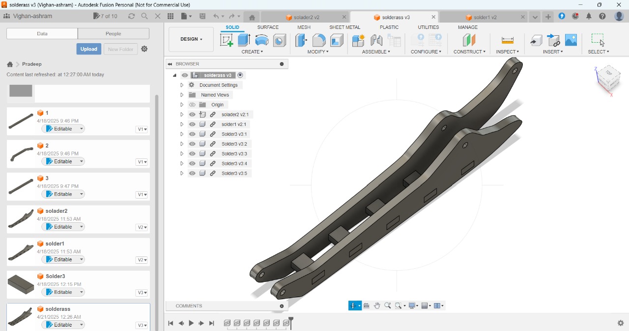
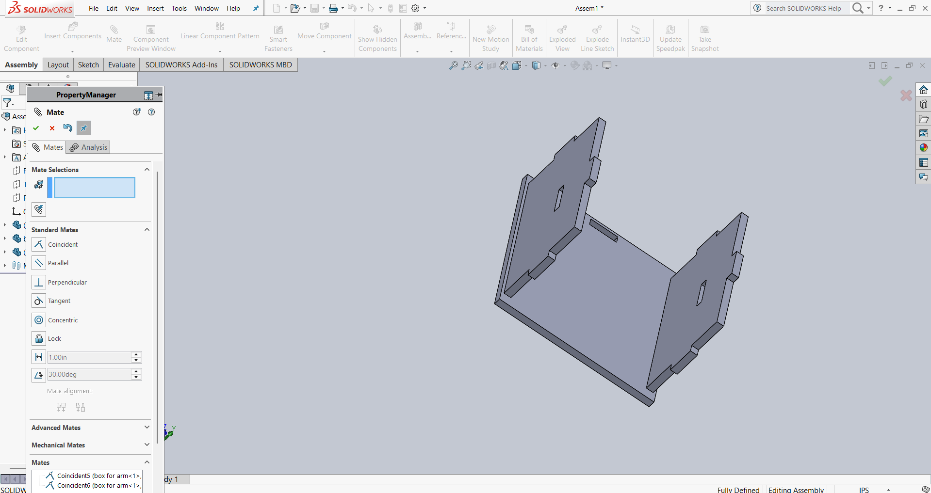
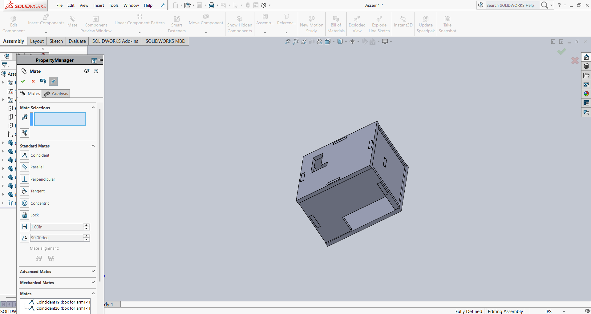
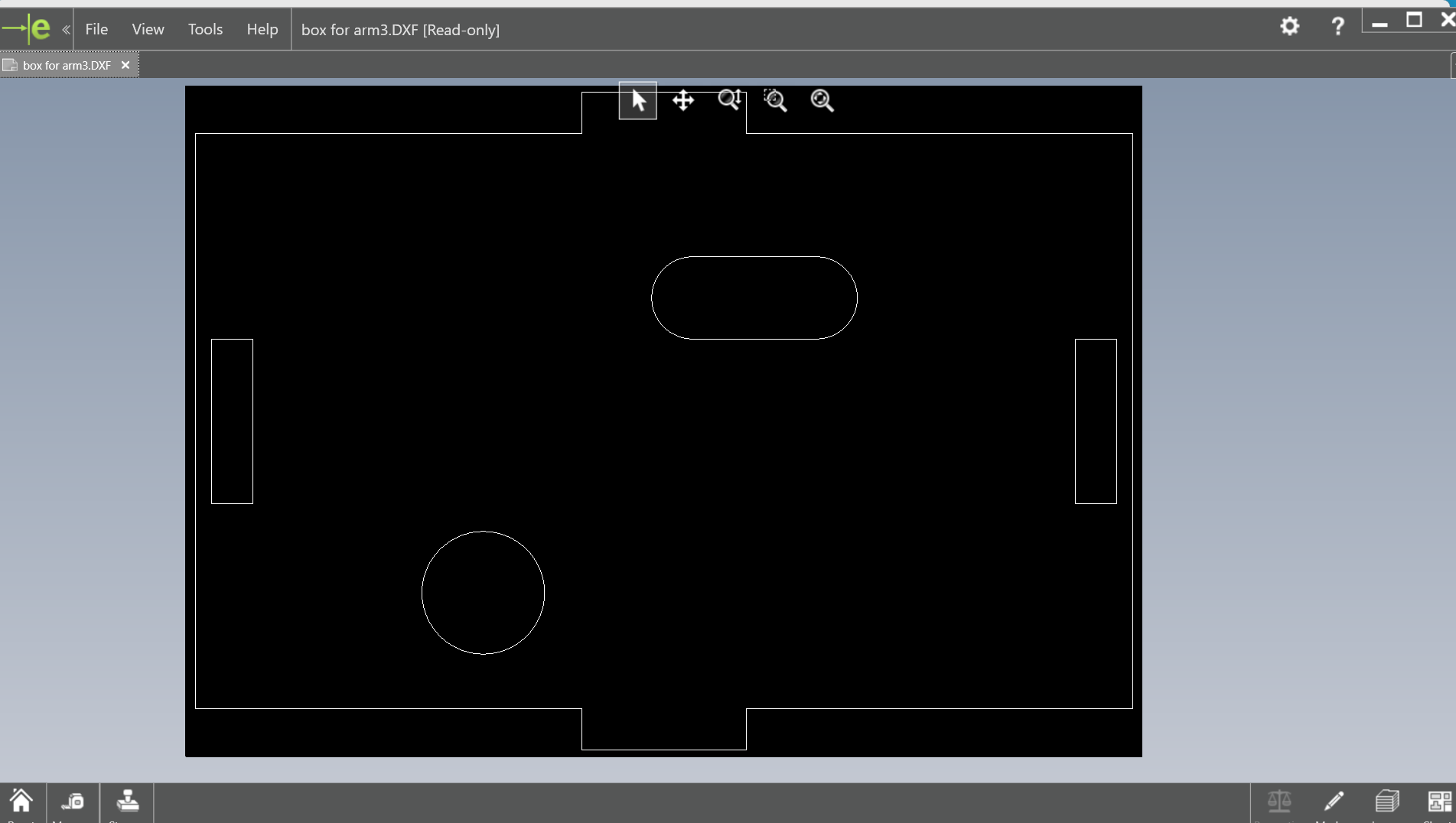
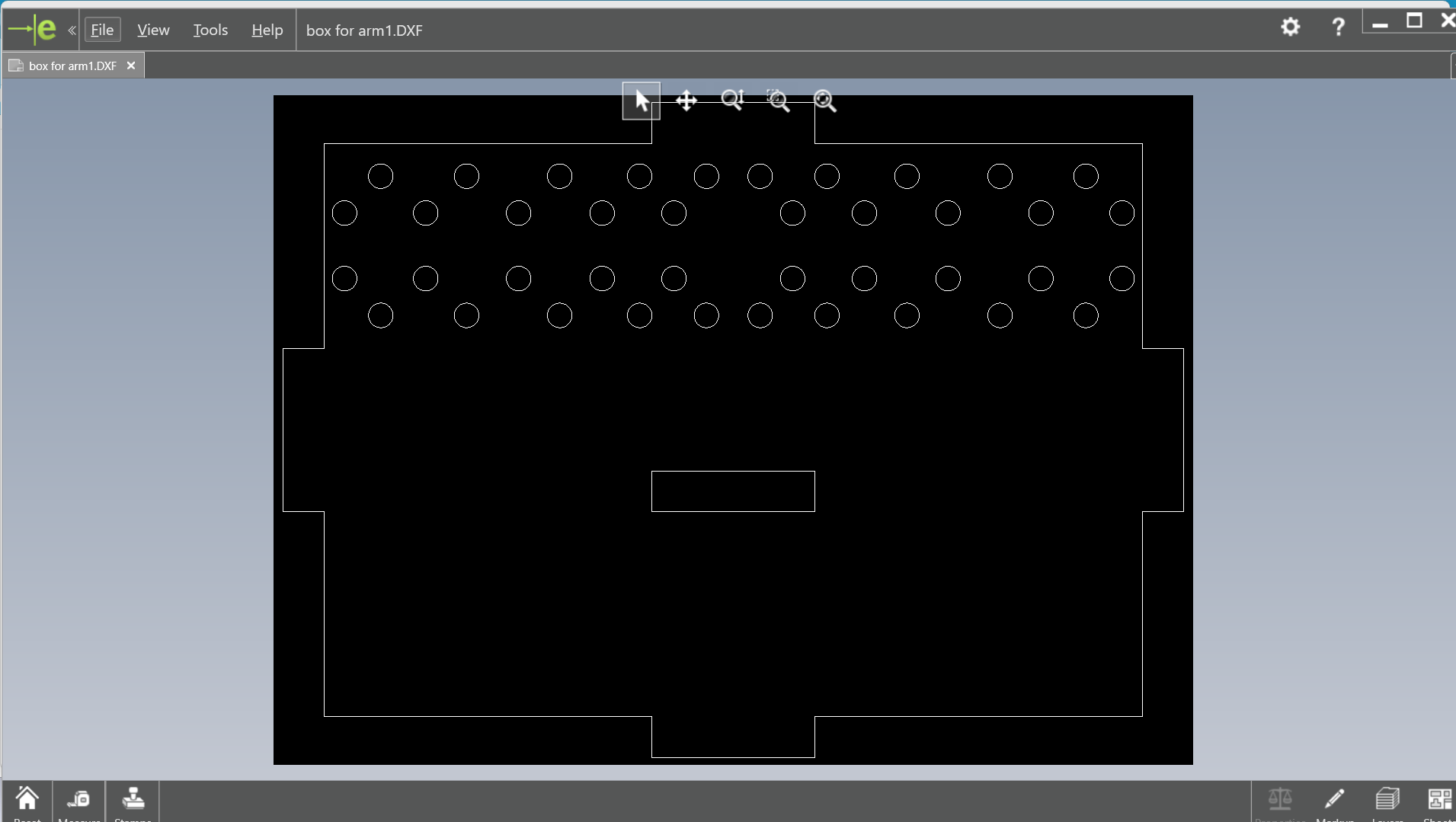
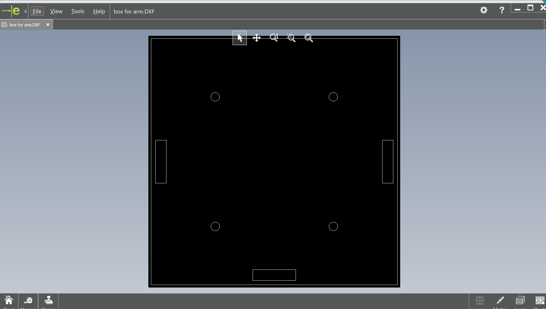
-Below is the assembly part of the arm, along with the designed box for the electronic components.
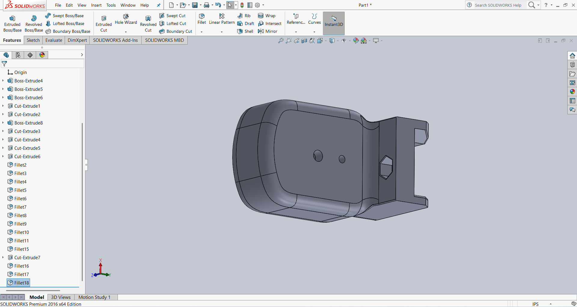
- Below is the end effector of the robotic arm, which is designed to perform specific tasks. It plays a crucial role in carrying out the intended operations, and its design ensures functionality and precision for various applications.
I was involved in creating and documenting the engineering and manufacturing Bill of Materials (BOM) for our entire machine.
Bill of Material:
| S.No | Item | Qty | Cost (INR) |
|---|---|---|---|
| 1 | XIAO -RP2040 | 1 | 400 |
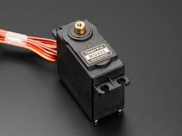
| 2 | Mg 995 Servo motors | 3 | 900 |
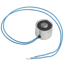
| 3 | Electromagnet | 1 | 200 |
| 4 | USB Webcam | 1 | 800 |
| 5 | Single Channel 5v Relay Module | 1 | 50 |
| 6 | nuts and bolts | num | 100 |
| 7 | 606zz bearing | 1 | 80 |
| 8 | M4 x 32mm threaded rod | 1 | 100 |
| 9 | M4 x 60mm threaded rod | 1 | 100 |
| 10 | 6 mm ball spheres | 25 | 120 |
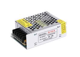
| 11 | Switched-mode power supply 5V 5AMP | 1 | 400 |
| TOTAL | 3250 | ||
Fabrication
1. Laser Cutting
Pradeep and Shivraj took responsibility for the fabrication work. I contributed by providing them with the DXF files and assisting during the process. We laser-cut the components box using acrylic and also cut all the linkage parts for the robotic arm using the laser cutter.
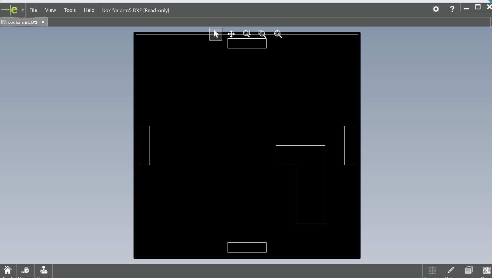
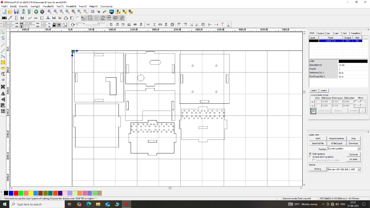
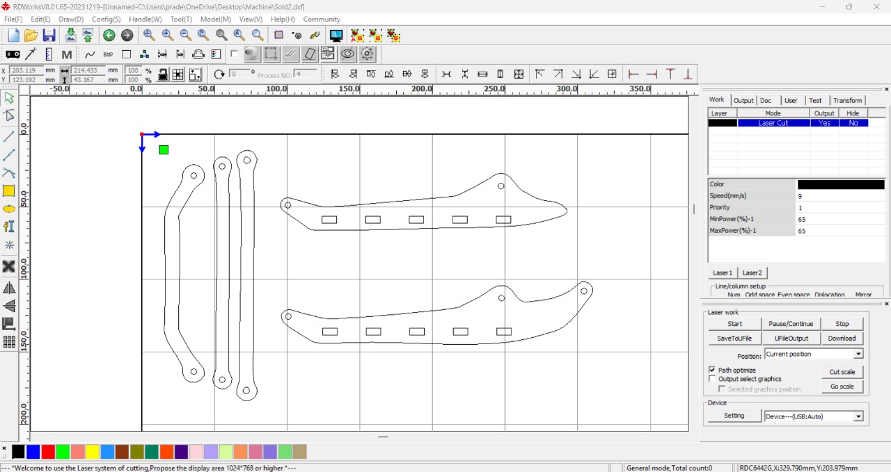
Below, we are showing how we set up the RDWorks software. This includes configuring the settings and preparing the file for laser cutting.
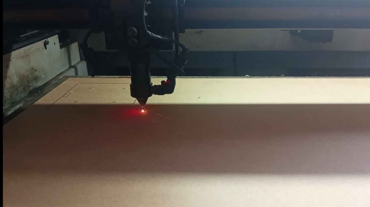
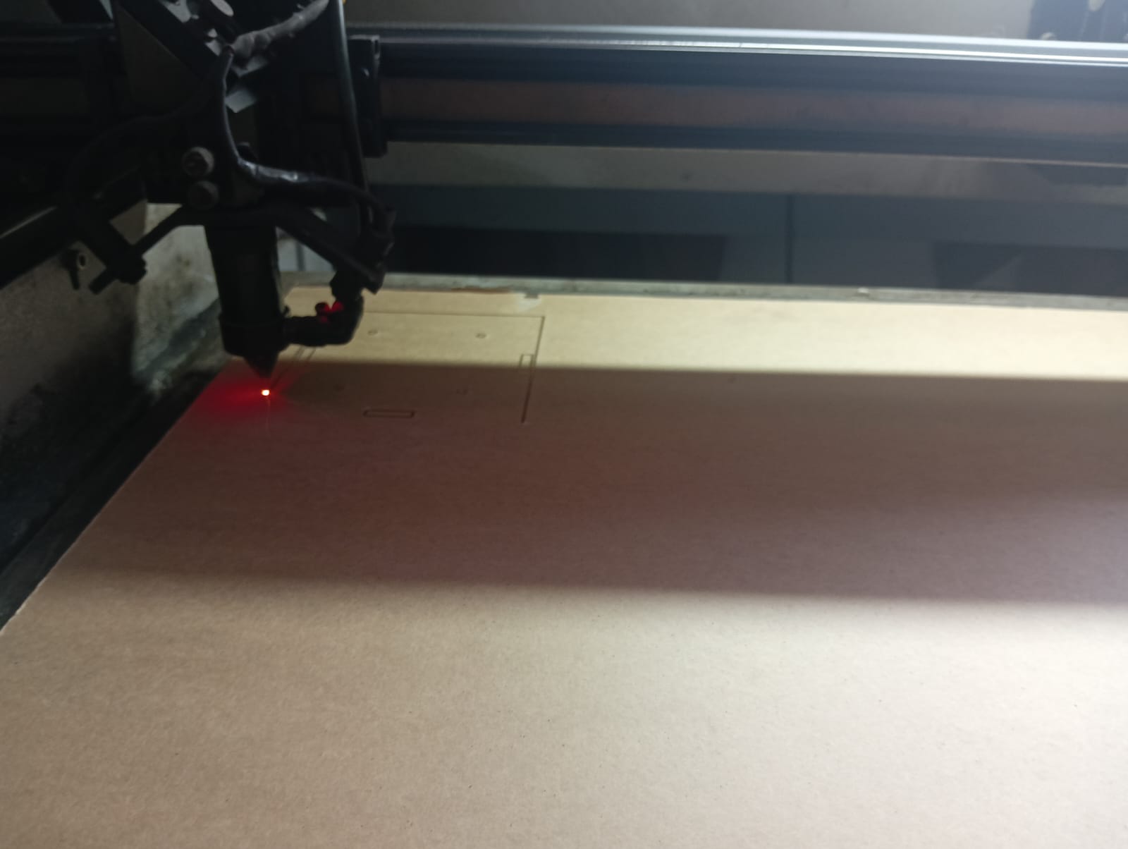
Below, we are showing the laser cutting process. We observed how the sheet was being cut accurately by the machine.
2. 3D Printing
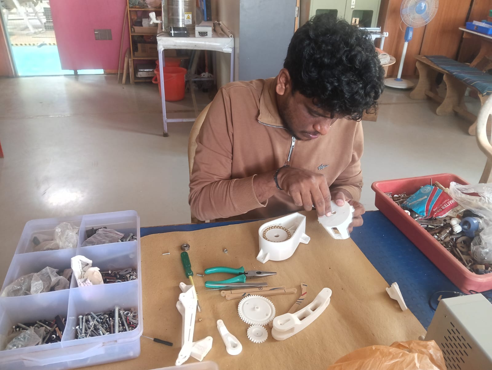
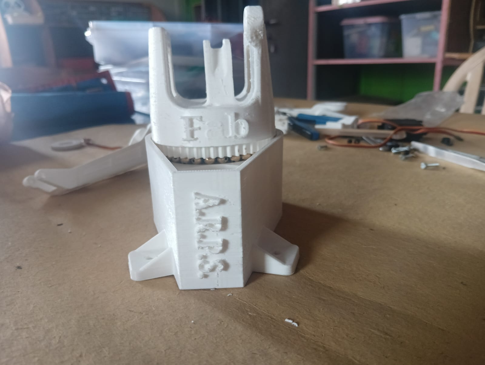
I contributed to setting up the 3D printing process along with Pradeep and Shivraj. They quickly designed the required parts for the robotic arm. We used a 3D printer to fabricate all the components, except for the linkage parts, which were made using laser cutting.
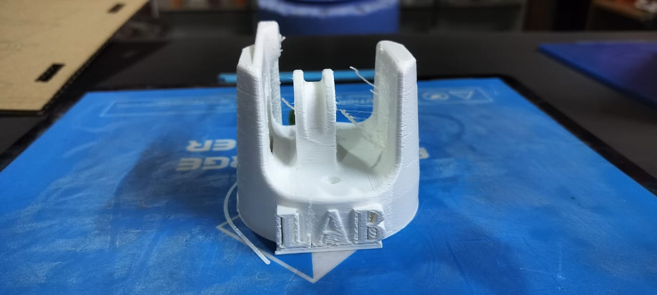
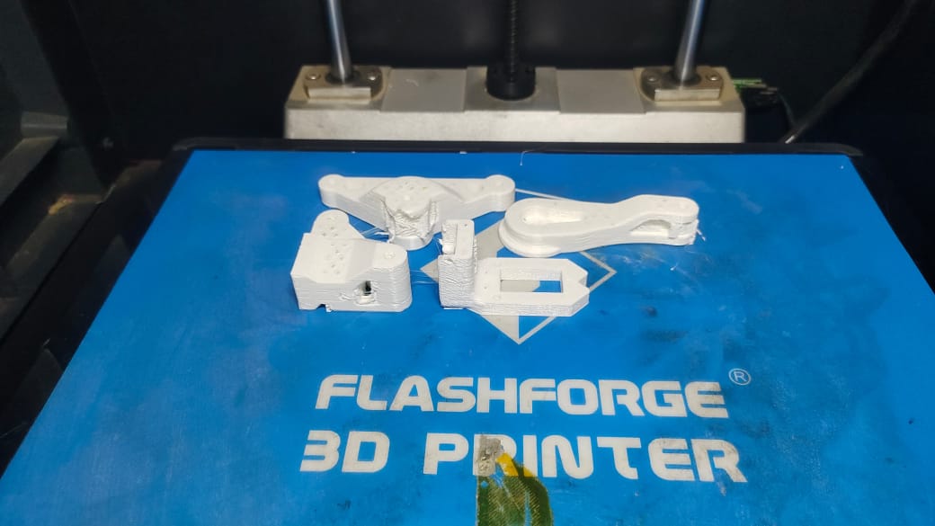
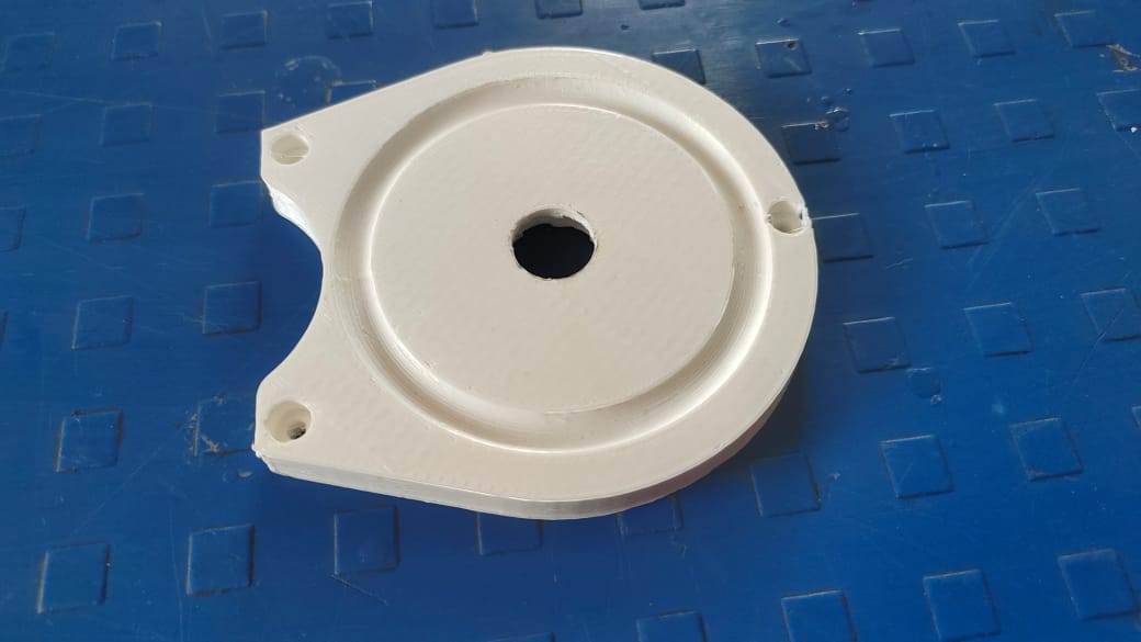
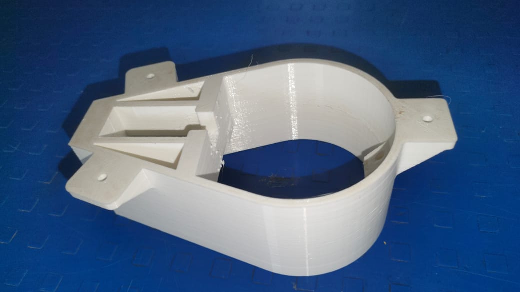
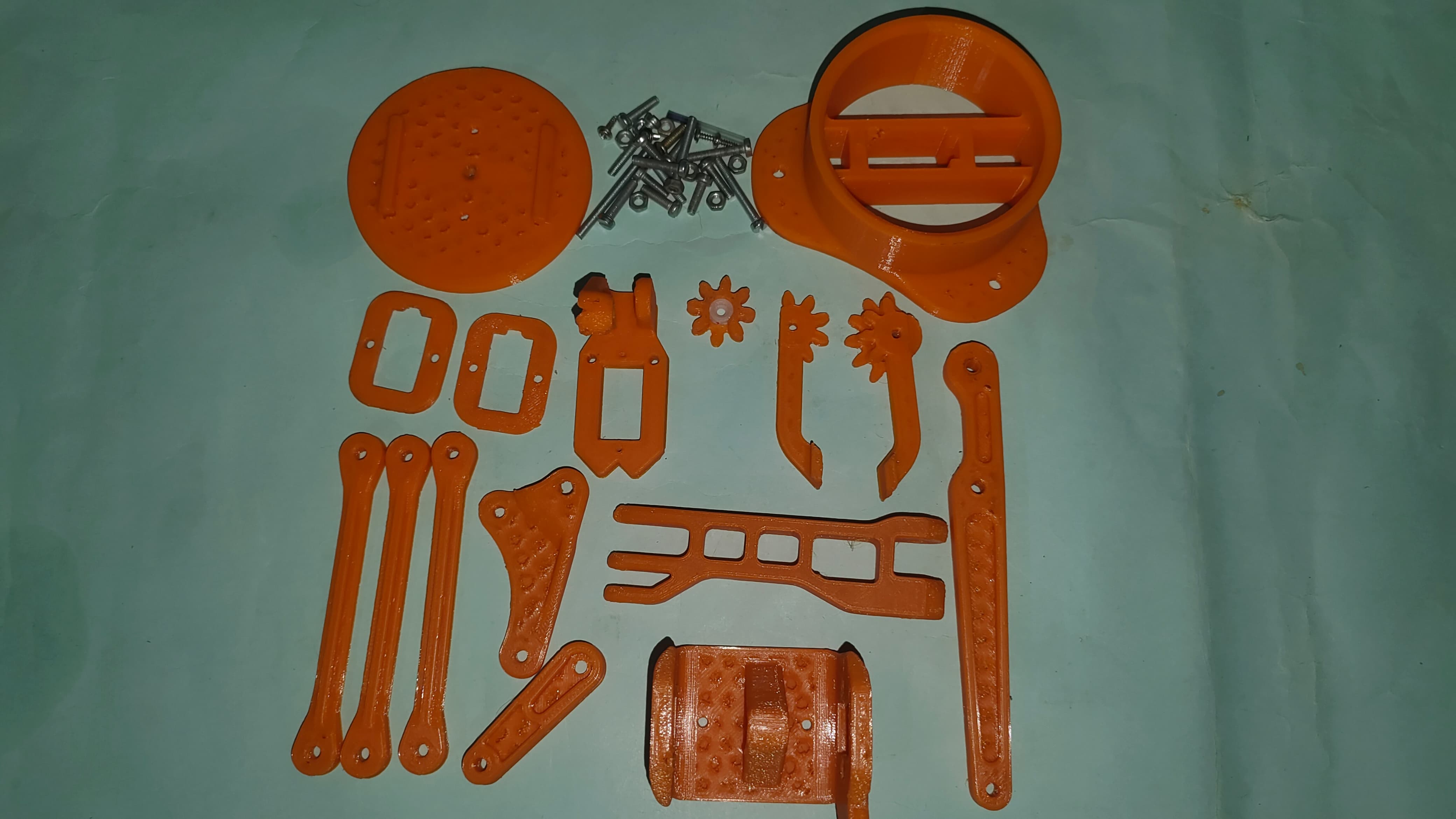
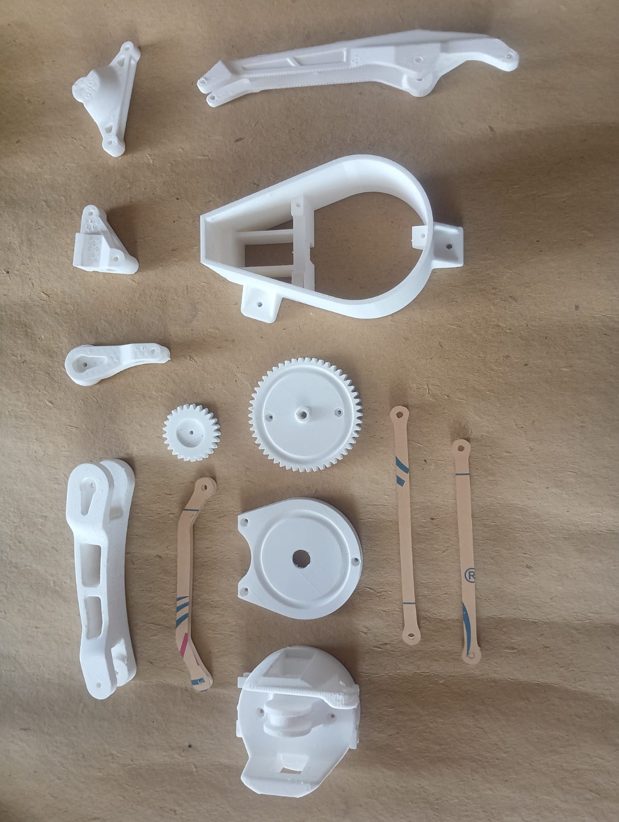
Finally, we printed all the parts. The image below shows all the completed 3D printed components.
3. Cutting and Grinding
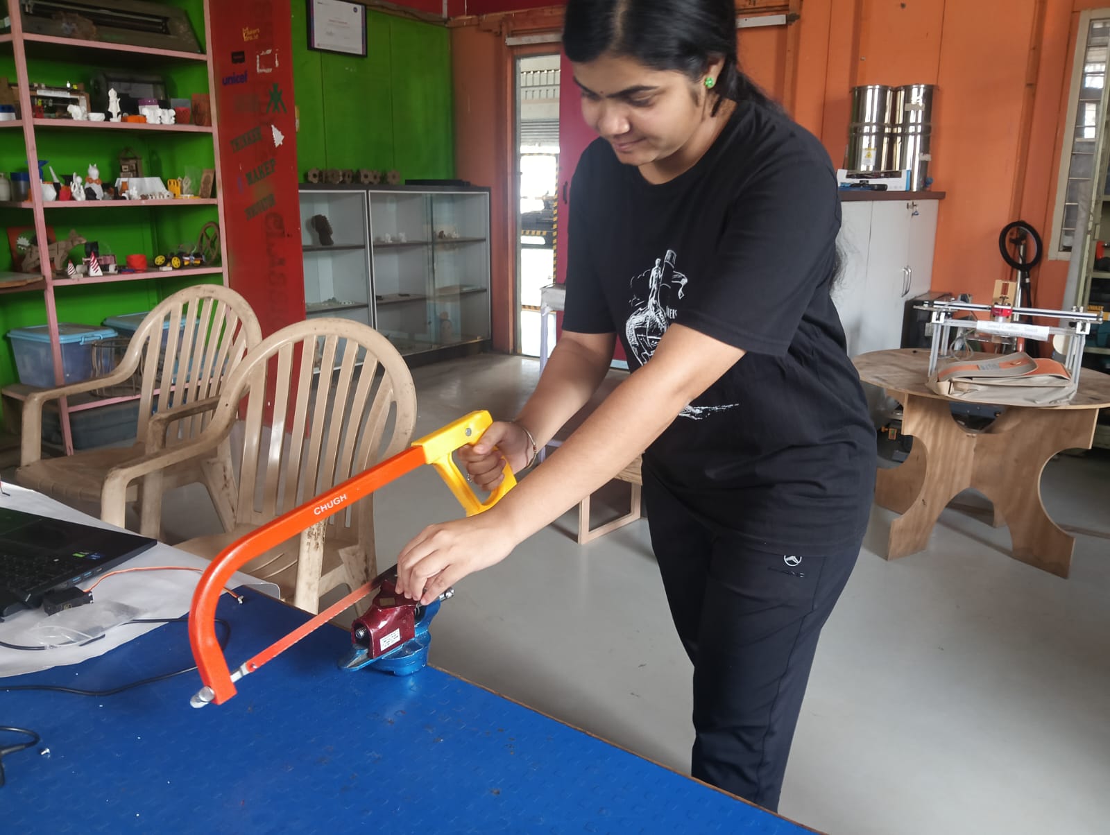
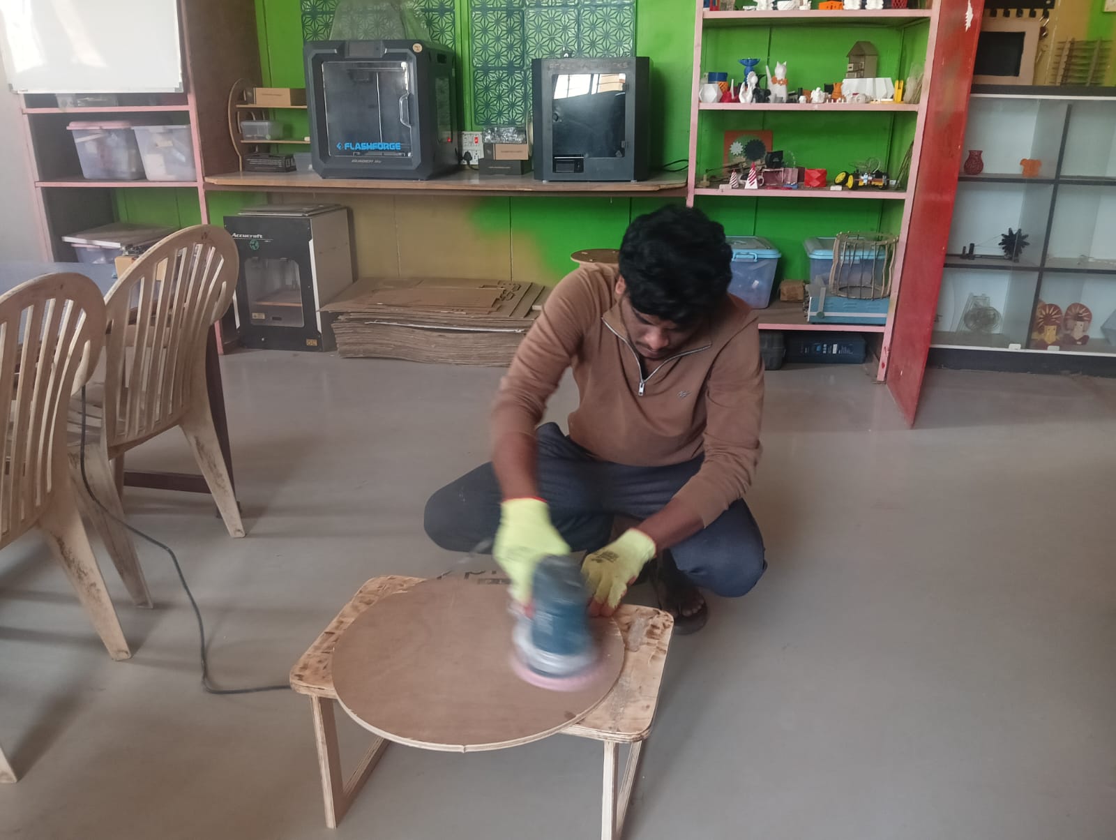
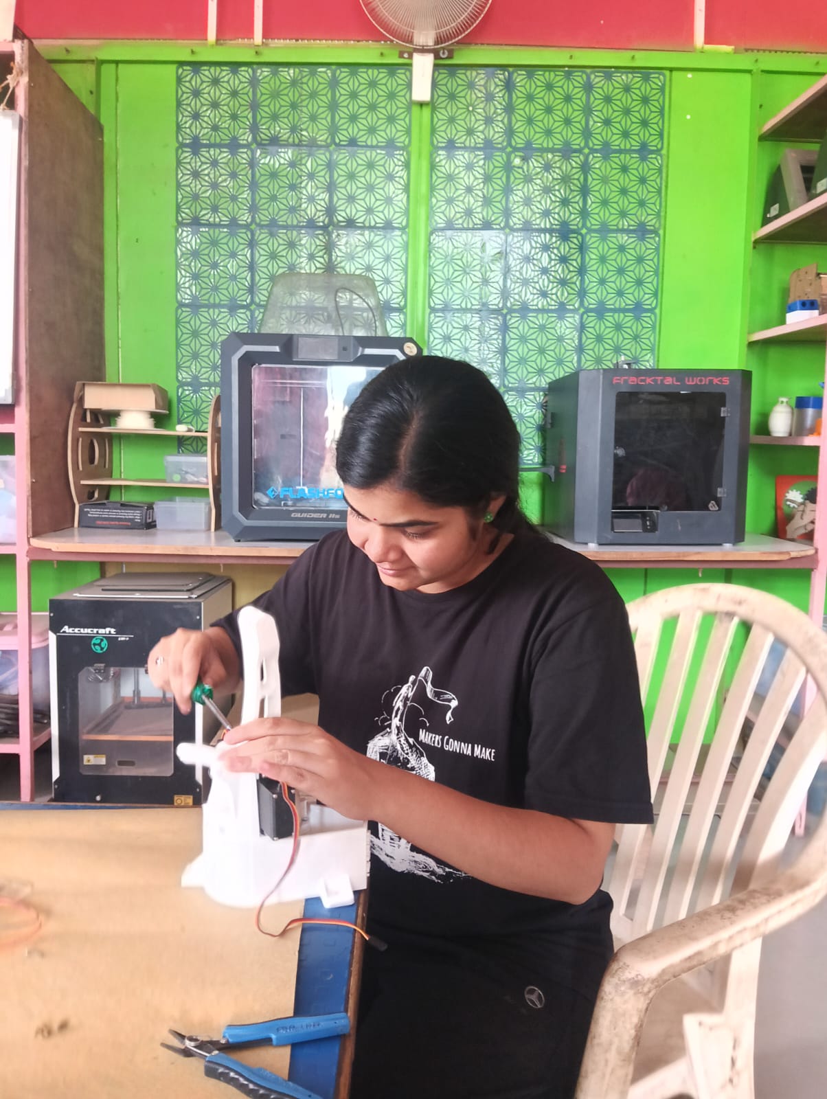
This is Arti. She is participating in Fab-X 2025 and also helped me during the machine week. She cut the M3 rods needed for the assembly of our project. Meanwhile, I worked on finishing the wooden base used for mounting the robotic arm.
Assembly
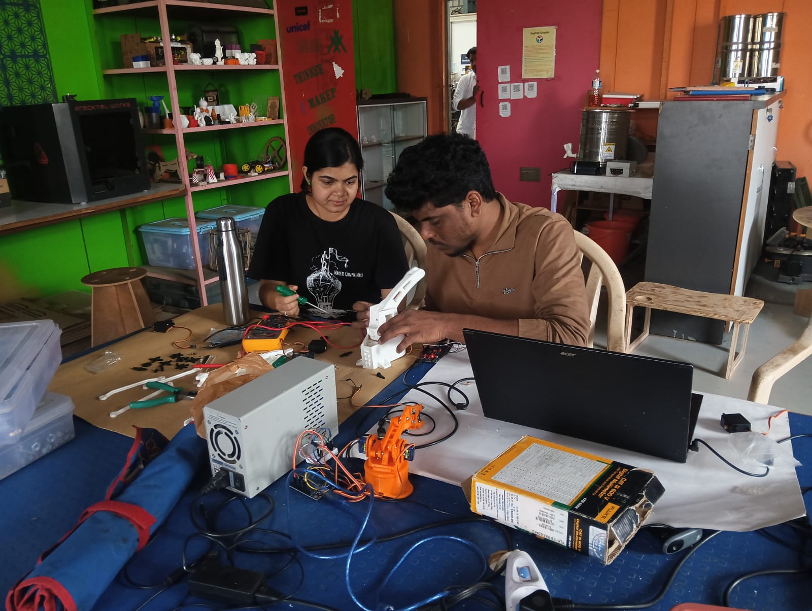
After gathering all the parts, including 3D printed and laser-cut components, along with nuts and bolts, we began assembling the robot.
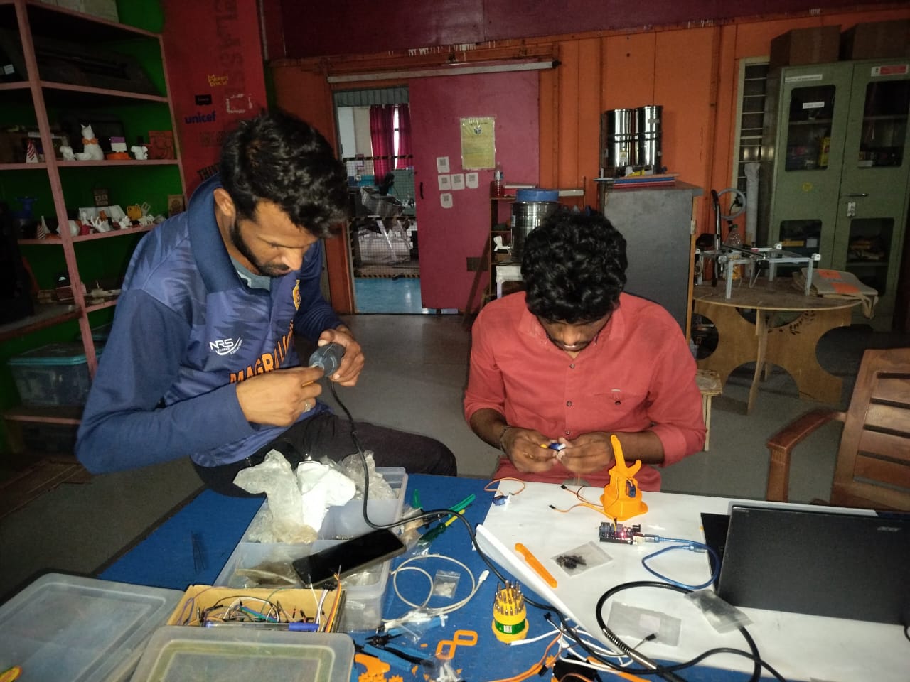
- Arti and I took responsibility for the assembly process. We assembled the robot step by step, carefully checking whether each servo motor was functioning properly and ensuring that every part was moving smoothly and correctly
Step 1: First, we fixed the base of the robot. The image below shows this step
Step 2: After completing the base, we assembled the shoulder and elbow arms, as shown in the image below.
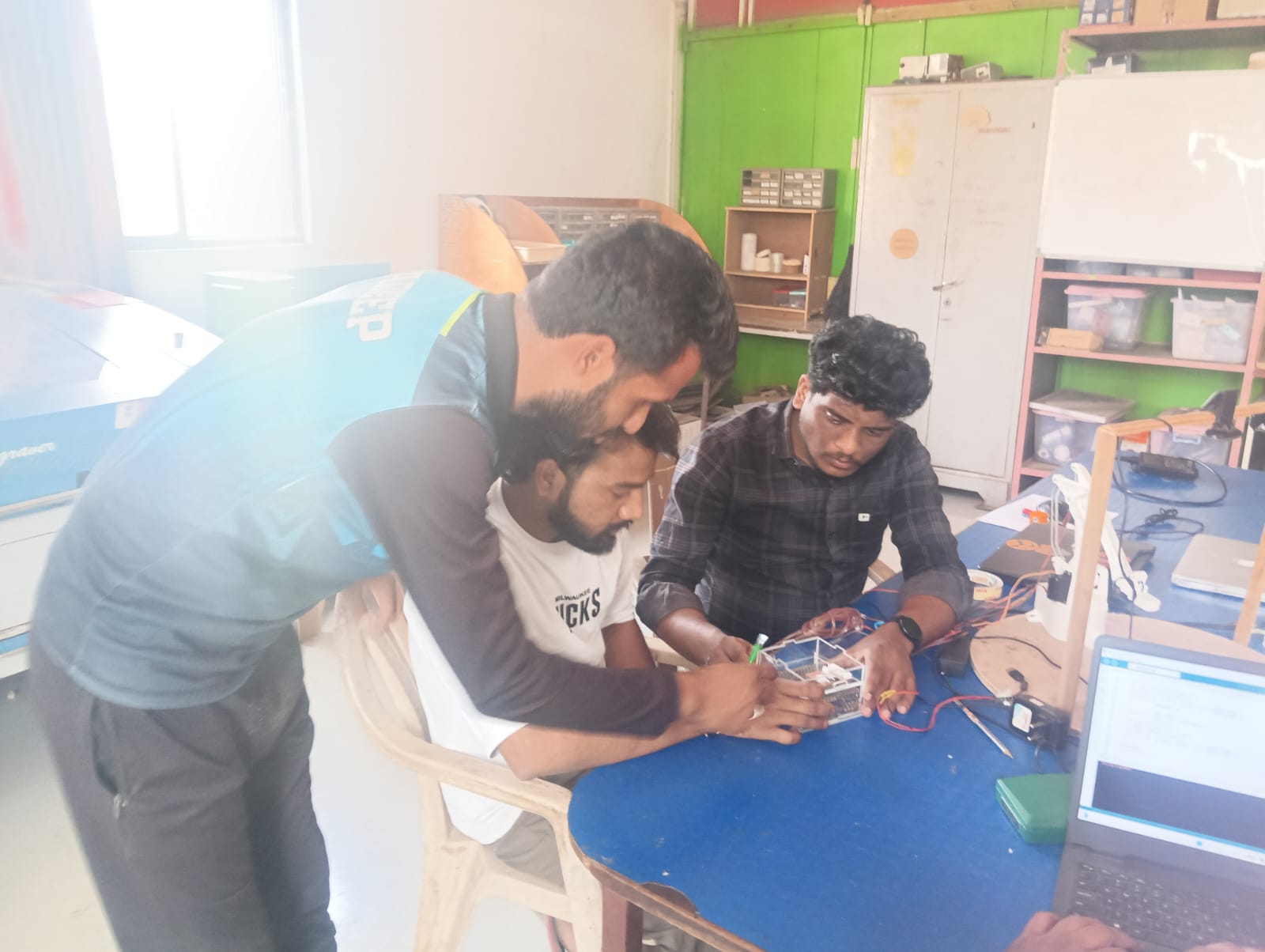
Step 3: We discussed the assembly with Suhas Sir, our supporting mentor in the lab. He gave us valuable guidance, which we followed, and finally completed the assembly of the robotic arm.
After completing the assembly, Shivraj and Pradeep started assembling the electronics box. This box helps keep all the electronic components safe and reduces the risk of short circuits.
Below, I am showing the final assembly of my machine.
Electronics Design, Assembly, and Robot Testing
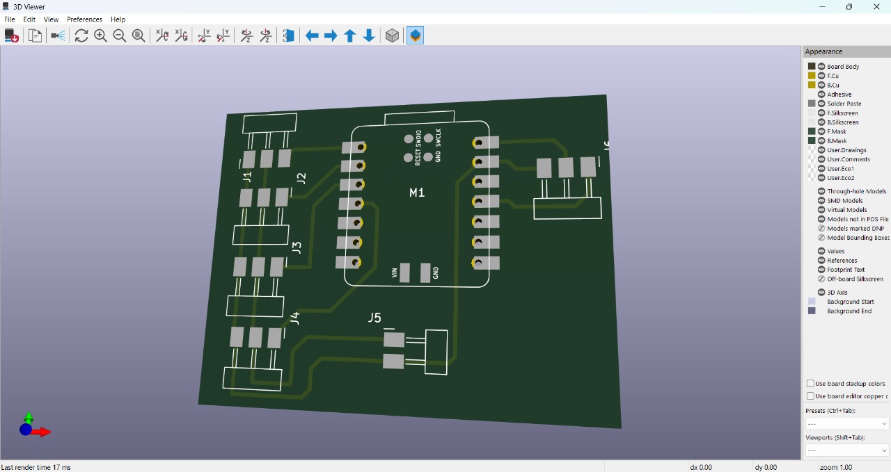
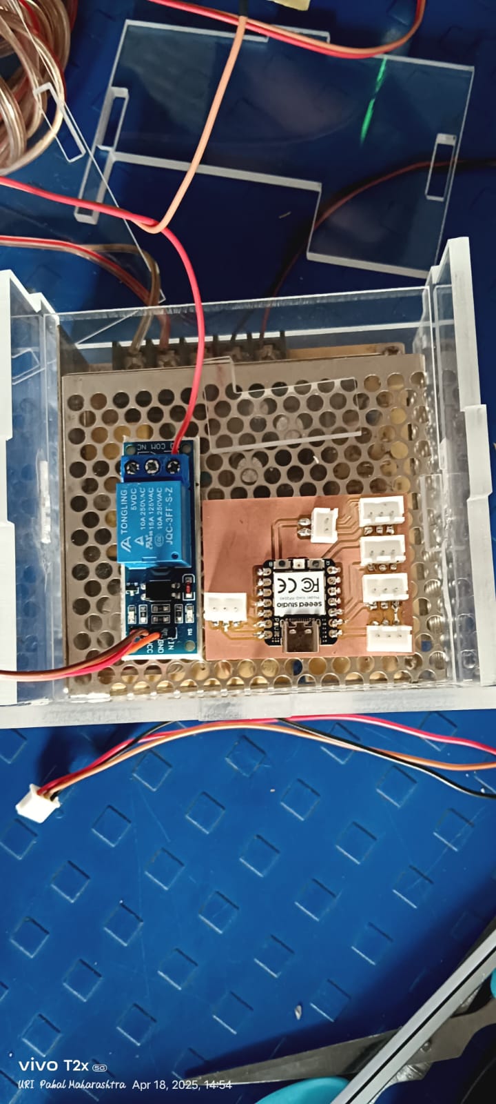
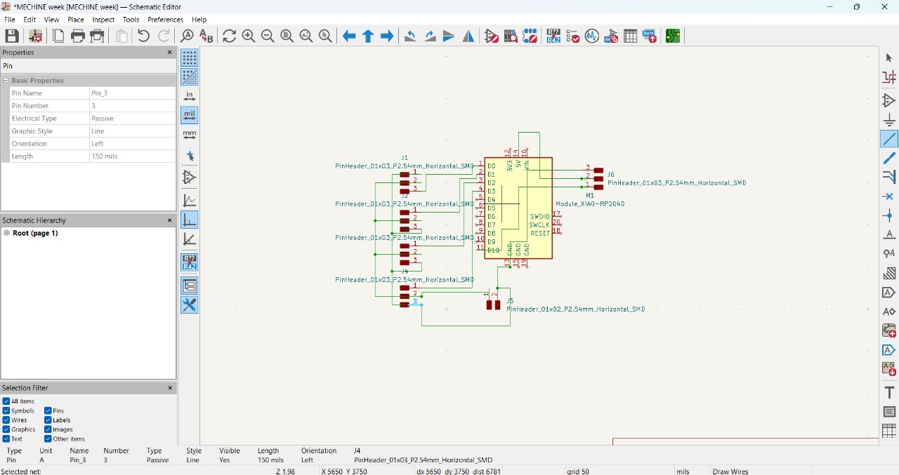
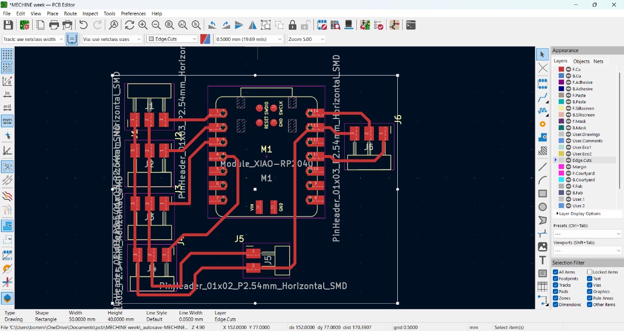
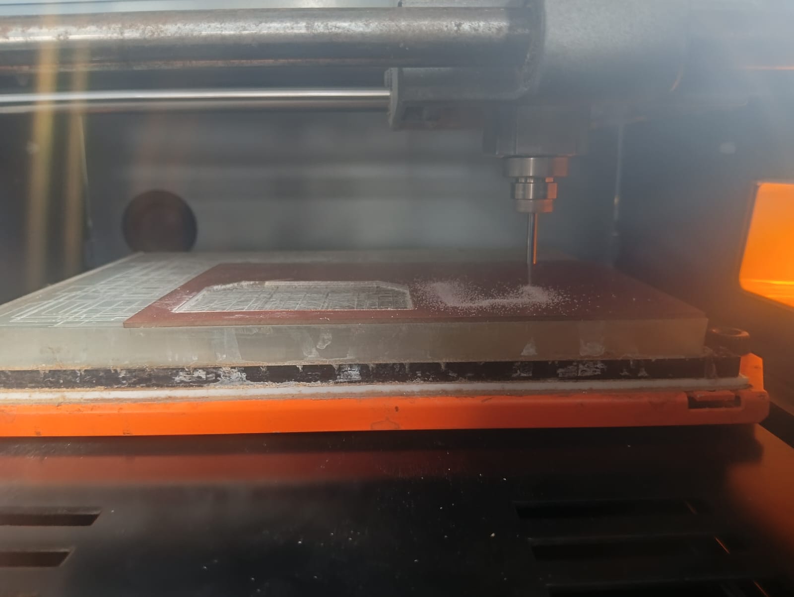
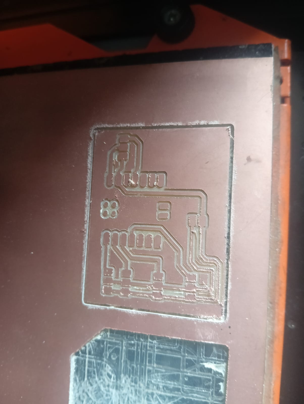
Shivraj took responsibility for the electronics design. For our final machine, we used the Xiao RP2040 module instead of Arduino boards. The PCB was designed using KiCad and milled using the SRM-20 machine. The process is shown in the images below.Below, I am showing the schematic sketch and the PCB layout design.
3D View of My PCB
After completing the PCB design, we proceeded with the PCB milling process.
After completing the milling process, we moved on to soldering. We soldered all the components according to our plan. Once soldering was done, all the connections were made to the robot, and we began the testing process.
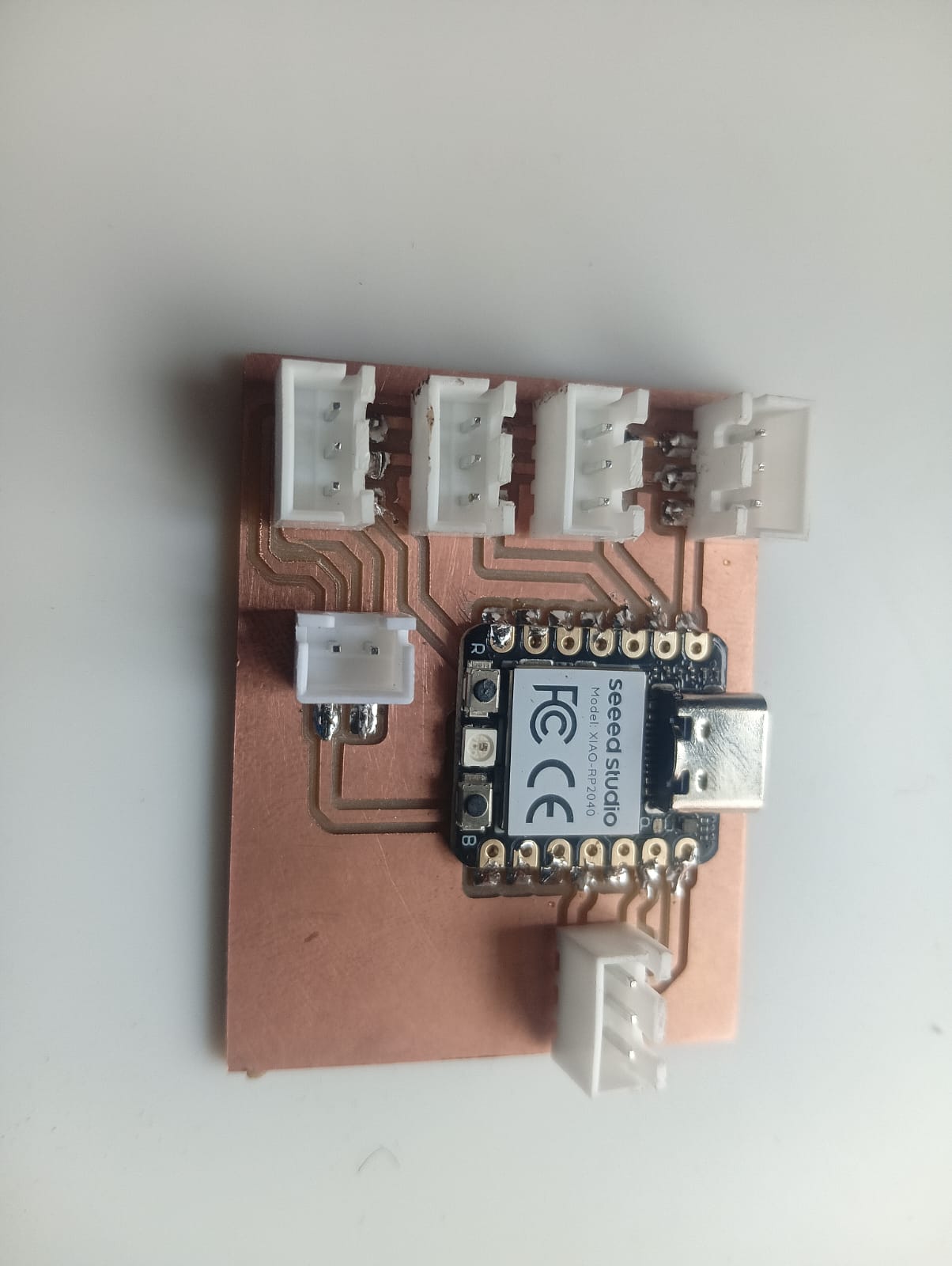
Electronic Hardware
We selected all the components based on the testing of our prototype. Before finalizing the selection, we referred to many components, and finally, we chose the best ones.
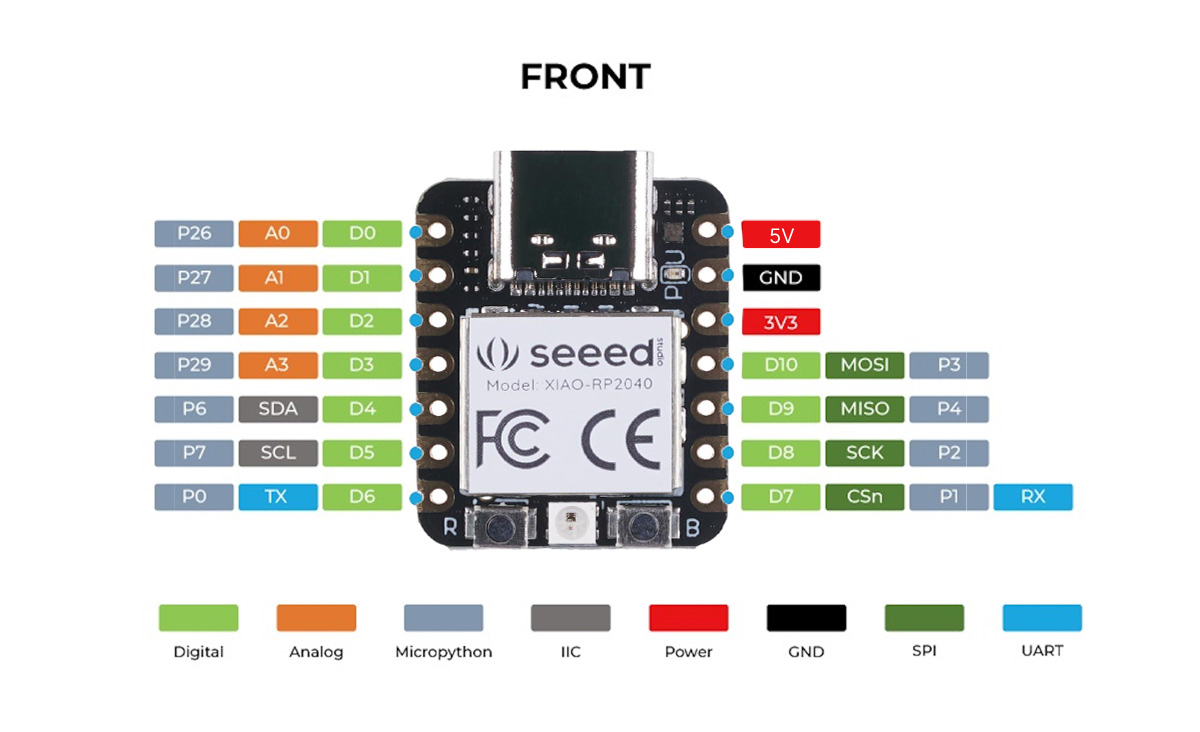
- Xiao RP2040
- MG995 Metal Gear Servo Motor
- 3-Pin Headers
- Webcam
- Electromagnetic Gripper
Selection of Servo Motor and Xiao RP2040 Controller
Based on the requirements and the results of the prototype robot, we selected the MG995 servo motor. In the prototype, we tested with fiber gears, but they didn’t work effectively. We also switched to the RP2040 microcontroller instead of using two Arduino boards, as it helped reduce the complexity of the code.
References: Reference1,Reference2
Selection of End Effector & Power Supply
After observing the results from our prototype, we found that the servo gripper was not very efficient. Therefore, we switched to an electromagnetic gripper, which operates on a 12V power supply. To control the end effector, we used a relay module, which significantly improved the overall efficiency of the system. For powering the machine, we used a 5V 3A power supply. This was necessary because each MG995 servo motor requires at least 1A of current, and since we are using three servo motors, a 3A power supply ensures stable operation.
References: Reference1,Reference2
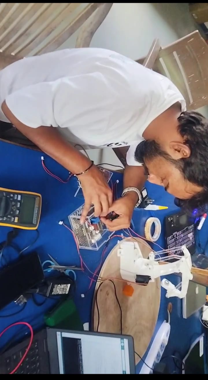
Testing of Electronic Components with Machine Running Servos
After successfully running all the servos using the test code, we proceeded directly to the final code. The outcome and results are shown below.
OpenCV Python code for object recognition
import cv2
import numpy as np
import serial
import time

# Initialize serial communication with Arduino
arduino = serial.Serial('COM42', 9600)  # Change this to your actual port
time.sleep(2)

# Calibration variables
KNOWN_HEIGHT_MM = 25.5
calibrated_pixel_height = None  # This will be set on calibration
pixel_to_mm_ratio = None

# Convert height in mm to lift servo angle
def height_to_lift_angle(height_mm):
    angle = np.interp(height_mm, [0, 100], [0, 180])
    return int(angle)

# Detect orange object
def detect_object(frame):
    hsv = cv2.cvtColor(frame, cv2.COLOR_BGR2HSV)
    lower_orange = np.array([10, 100, 100])
    upper_orange = np.array([25, 255, 255])
    mask = cv2.inRange(hsv, lower_orange, upper_orange)
    contours, _ = cv2.findContours(mask, cv2.RETR_EXTERNAL, cv2.CHAIN_APPROX_SIMPLE)

    if contours:
        largest = max(contours, key=cv2.contourArea)
        x, y, w, h = cv2.boundingRect(largest)
        center_x, center_y = x + w // 2, y + h // 2

        # Draw
        cv2.rectangle(frame, (x, y), (x + w, y + h), (0, 255, 0), 2)
        cv2.circle(frame, (center_x, center_y), 5, (255, 0, 0), -1)

        return center_x, center_y, h
    return None, None, None

# Video capture
cap = cv2.VideoCapture(0)
object_detected = False

print("Press 'c' to calibrate with known object height (25.5mm).")

while True:
    ret, frame = cap.read()
    if not ret:
        break

    obj_x, obj_y, obj_h_px = detect_object(frame)

    if obj_x is not None:
        if calibrated_pixel_height is not None:
            pixel_to_mm_ratio = KNOWN_HEIGHT_MM / calibrated_pixel_height
            estimated_height_mm = obj_h_px * pixel_to_mm_ratio
            servo_base = int(np.interp(obj_x, [0, frame.shape[1]], [0, 180]))
            servo_arm = int(np.interp(obj_y, [0, frame.shape[0]], [180, 0]))
            servo_lift = height_to_lift_angle(estimated_height_mm)

            if not object_detected:
                command = f"{servo_base},{servo_arm},{servo_lift}\n"
                arduino.write(command.encode())
                print(f"Sent: {command.strip()} | Height: {estimated_height_mm:.2f} mm")
                object_detected = True

        else:
            cv2.putText(frame, "Press 'c' to calibrate", (10, 30),
                        cv2.FONT_HERSHEY_SIMPLEX, 0.7, (0, 0, 255), 2)

    cv2.imshow("Object Detection", frame)

    key = cv2.waitKey(1) & 0xFF
    if key == ord('q'):
        breakqq

    elif key == ord('r'):
        object_detected = False
        print("Detection reset.")
    elif key == ord('c') and obj_h_px is not None:
        calibrated_pixel_height = obj_h_px
        print(f"Calibrated with {calibrated_pixel_height} pixels = 25.5mm")

cap.release()
cv2.destroyAllWindows()
arduino.close()
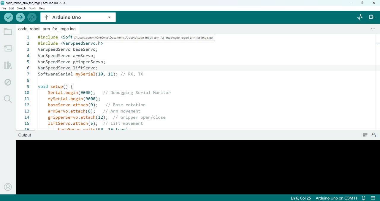
Arduino code for operating the servo motors
#define SUPPRESS_HPP_WARNING
#include <ServoEasing.hpp>

ServoEasing baseServo;
ServoEasing armServo;
ServoEasing liftServo;

int rely = 29;
int baseAngle = 90;
int armAngle = 90;
int liftAngle = 90;

void setup() {
Serial.begin(9600);
pinMode(rely, OUTPUT);
digitalWrite(rely, LOW);

baseServo.attach(26);
armServo.attach(27);
liftServo.attach(28);

baseServo.setSpeed(15); // 0 (fastest) to 255 (slowest)
armServo.setSpeed(15);
liftServo.setSpeed(15);
}

void loop() {
baseServo.easeTo(0);
delay(100);
armServo.easeTo(90);
delay(100);
liftServo.easeTo(90);
digitalWrite(rely, LOW);

if (Serial.available()) {
String data = Serial.readStringUntil('\n');
int comma1 = data.indexOf(',');
int comma2 = data.lastIndexOf(',');

if (comma1 > 0 && comma2 > comma1) {
baseAngle = data.substring(0, comma1).toInt();
armAngle = data.substring(comma1 + 1, comma2).toInt();
liftAngle = data.substring(comma2 + 1).toInt();

// Clamp angles between 0 and 180
baseAngle = constrain(baseAngle, 0, 180);
armAngle = constrain(armAngle, 0, 180);
liftAngle = constrain(liftAngle, 0, 180);

// Move the servos
baseServo.easeTo(baseAngle);
armServo.easeTo(armAngle);
liftServo.easeTo(liftAngle);
delay(100);
digitalWrite(rely, HIGH);
delay(100);
liftServo.easeTo(90);
delay(100);
armServo.easeTo(110);
delay(100);
}
}
}
Final Journey Video - Make a Machine Week
Final Presentation Video
Individual Assignment Brief :
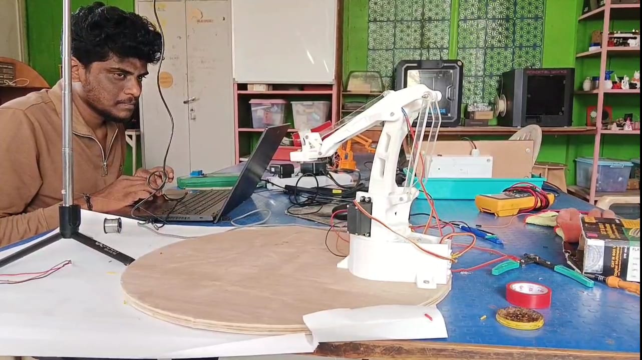
In this week's Machine assignment, I worked on the programming part of the machine. I started by writing a program for image recognition and then tested it on the prototype of the machine.
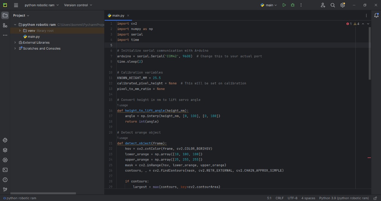
After that, I opened the Arduino IDE and started writing the program for serial control. I used PyCharm to handle the image recognition and communication with the Arduino.
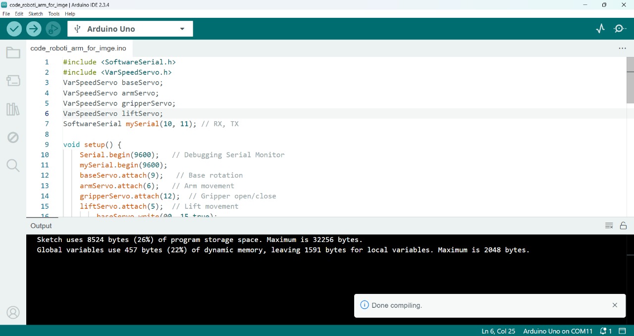
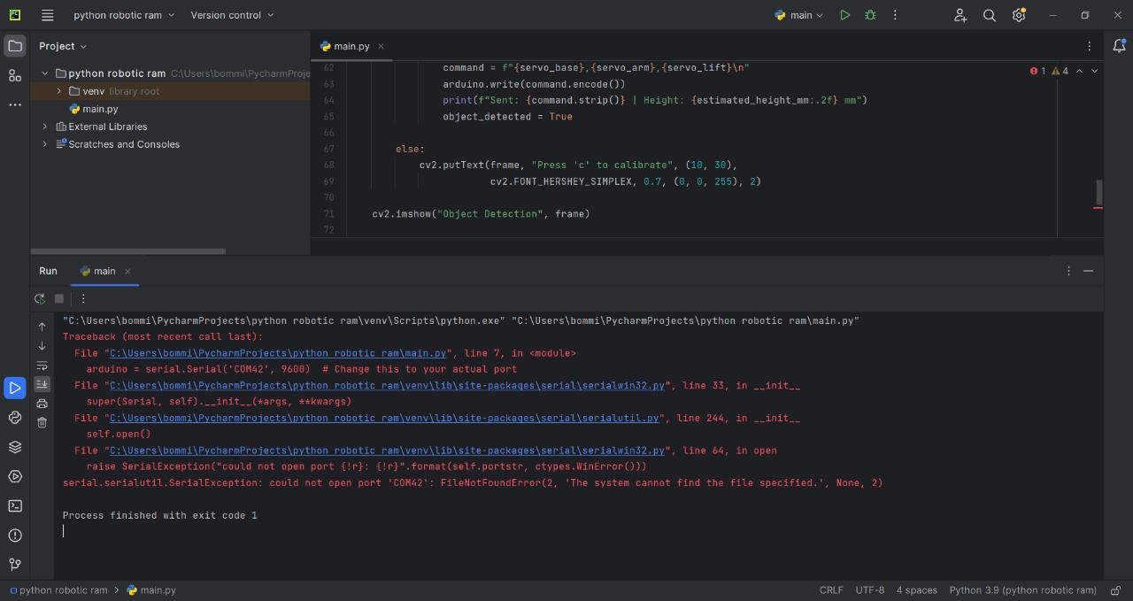
After uploading the code, the results are shown below.
After seeing the results, I understood what the problem was. So, I decided to control the speed of the servo motors. For that, I added a servo speed control library in Arduino, then uploaded the code again and tested it. The updated results are shown below.
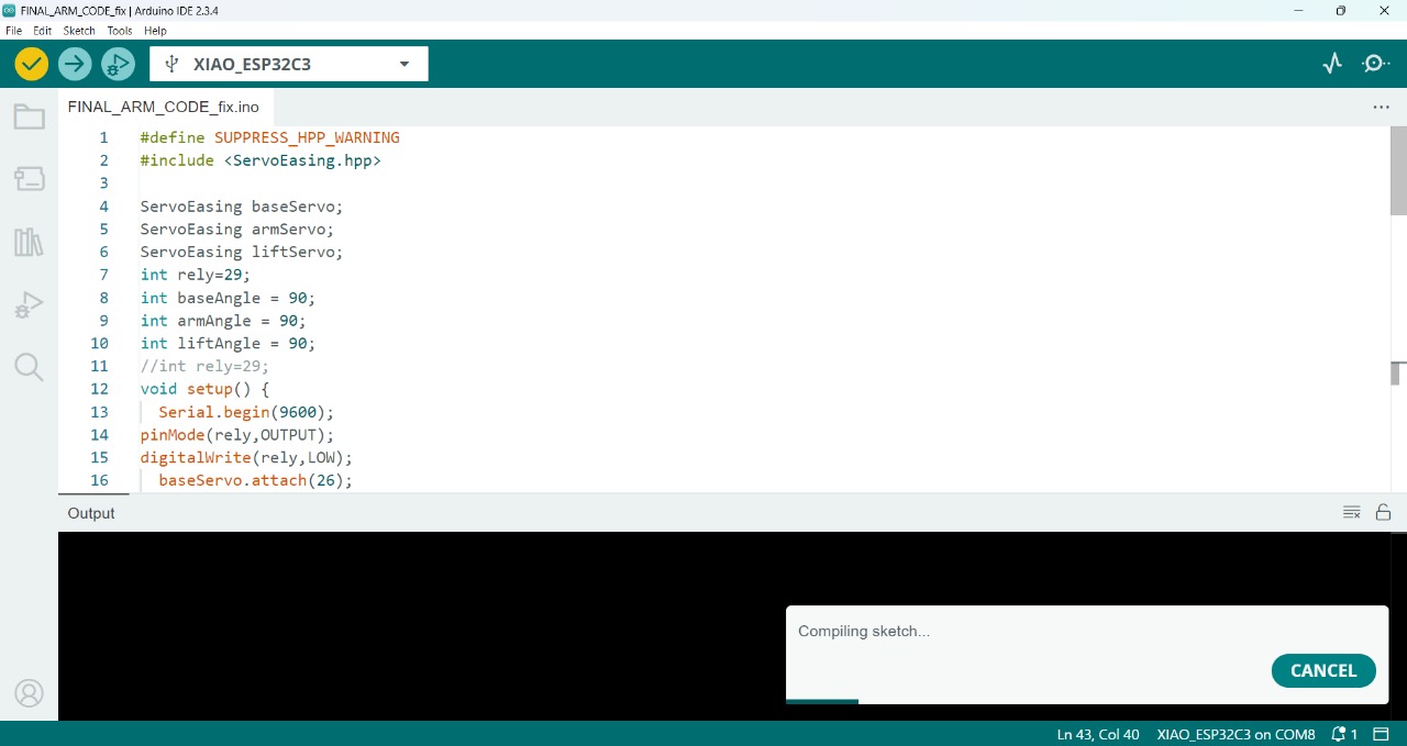
After successfully testing the prototype, we moved on to the final machine, which I included in the group assignment. I used the same code for the final machine but made some changes in the Arduino code because I used an Arduino Uno for testing the prototype, whereas in the final machine, I used the RP2040 controller. The updated code with those changes is included below given files.
After successfully uploading all the codes, the final results are shown below.
Original Files for download:
Download programming filesdownloading CAD files click Here
Positive Outcomes:
During the group assignment, I learned a lot about effective communication and teamwork. We discussed various design ideas and decided together on the types of parts to use. This collaboration helped me understand the importance of planning and decision-making in a team setting.
In the individual assignment, I explored the programming aspects more deeply. I improved my coding skills significantly by testing different logics and debugging errors. I also gained hands-on experience with microcontrollers, sensors, and servo control. Overall, this week helped me grow both technically and in terms of working with others.
Challenges Encountered:
This week, I faced several challenges, especially during programming and assembly. One of the major issues was understanding object detection — initially, I couldn't figure out how or where the object was being detected. After some exploration and testing, I managed to calibrate it properly by creating a custom setup.
When it came to Arduino programming, the servo motors were moving too fast and uncontrollably. I searched for a library that could help control the speed through code, and I found one. However, that library was not compatible with the Xiao RP2040 controller I was using. So again, I had to dig deeper and eventually found a different library that worked well with my setup. This troubleshooting process taught me a lot about patience and problem-solving in real-time.