Assignment 11: Embedded Networking and Communications
In my Networking and Communications week assignment, I explored both wired and wireless communication for connecting my project board to different devices. Initially, I tested the setup using **random values to check functionality. Later, I successfully integrated an LCD display and Wi-Fi communication, which will play a key role in my final project. I studied different communication protocols, understanding their importance in data transmission. Choosing the right protocol based on **speed, reliability, and application** was crucial. The successful setup of LCD and Wi-Fi marked a significant milestone in my project. However, I faced challenges like connectivity issues and unstable data transmission. Troubleshooting these problems enhanced my understanding of **debugging and optimizing networks**. This experience provided valuable insights into real-world networking applications. It also helped me refine my project’s communication framework for future development.
Highlight Moments of the Week
Basics of Networking and Communication
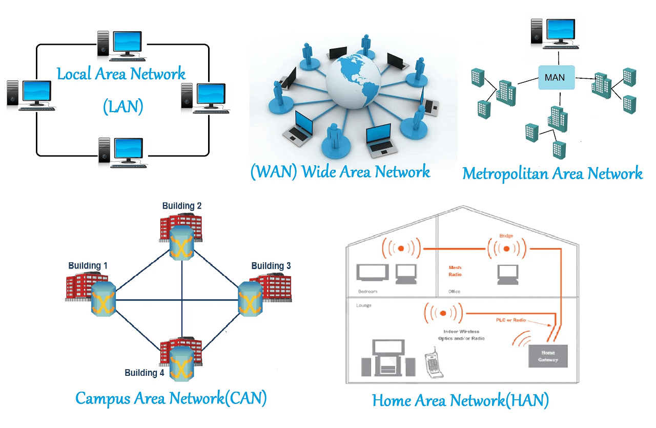
Networking and communication in embedded systems enable devices like Arduino and ESP32 to exchange data efficiently. Communication can be wired (using UART, I2C, SPI) or wireless (via Wi-Fi, Bluetooth, ESP-NOW, LoRa). Each protocol has its own advantages, depending on factors like speed, range, and power consumption. Understanding these methods helps in building IoT projects, automation systems, and real-time applications. Choosing the right protocol ensures reliable data transmission and seamless device integration in any project. Reference Reference
Before explaining what I did in this week’s assignment, I would like to describe the types of communication methods used in the assignment.
1. Wired communication between two microcontroller boards:
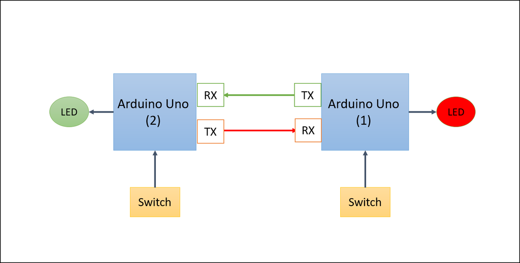
Wired communication between two microcontroller boards involves connecting them through physical wires to share data. This method is reliable and fast, making it ideal for short-distance communication. Common protocols used include UART, I2C, and SPI, depending on the project needs. It requires proper connection of pins like TX and RX for UART, along with a shared ground. In my assignment, I explored how data is transmitted and received directly through these wired connections.
References: Reference
2.ESP-NOW wireless communication protocol:
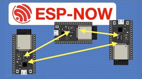
ESP-NOW is a unique wireless communication protocol developed by Espressif for the ESP32 microcontroller, enabling direct communication between devices without the need for a Wi-Fi network or internet connection. It operates on a peer-to-peer basis, allowing multiple devices to send and receive small amounts of data efficiently. ESP-NOW is known for its low power consumption, making it ideal for battery-operated devices. The protocol supports both unicast (one-to-one) and broadcast (one-to-many) communication modes, providing flexibility in data sharing. With its simple setup and fast transmission speeds, ESP-NOW is well-suited for applications like sensor networks, remote control systems, and IoT devices.
References: Reference
3. Wi-Fi Communication in ThingSpeak for IoT Connectivity:
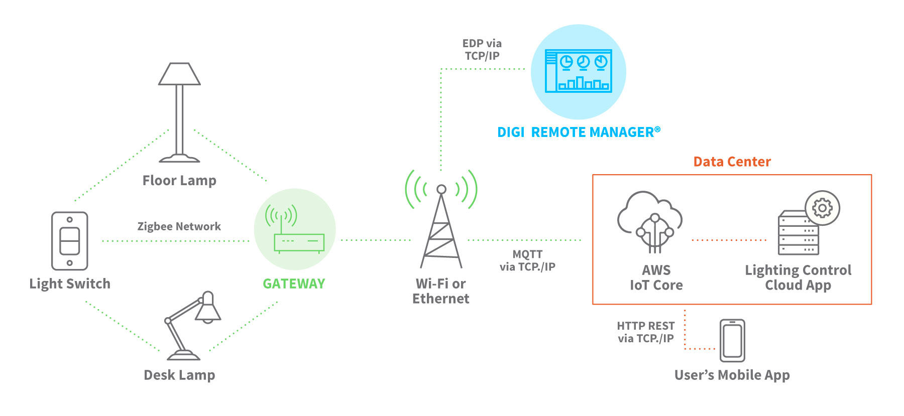
Wi-Fi Communication in ThingSpeak for IoT Connectivity allows devices to interact over a local network using standard wireless signals. This method makes it easy to send and receive data between sensors, microcontrollers, and cloud services. It provides a reliable and fast connection, which is essential for real-time monitoring and control. In ThingSpeak, Wi-Fi helps link physical devices to digital applications seamlessly. This approach is ideal for building smart systems that need internet access and consistent data flow.
References: Reference
Group Assignment
Objective of the Group Assignment
- send a message between two projects
Click here for Group Assignmen.Individual Assignment
Objective of the Individual Assignment:
- design, build, and connect wired or wireless node(s)
- with network or bus addresses and local input &/or output device(s)
For my Individual Assignment, I used three different types of communication. I have already explained each method above in detail. Now, I will briefly describe the inputs and outputs used in each communication setup.
1. Serial communication between two ESP32-C3 boards:
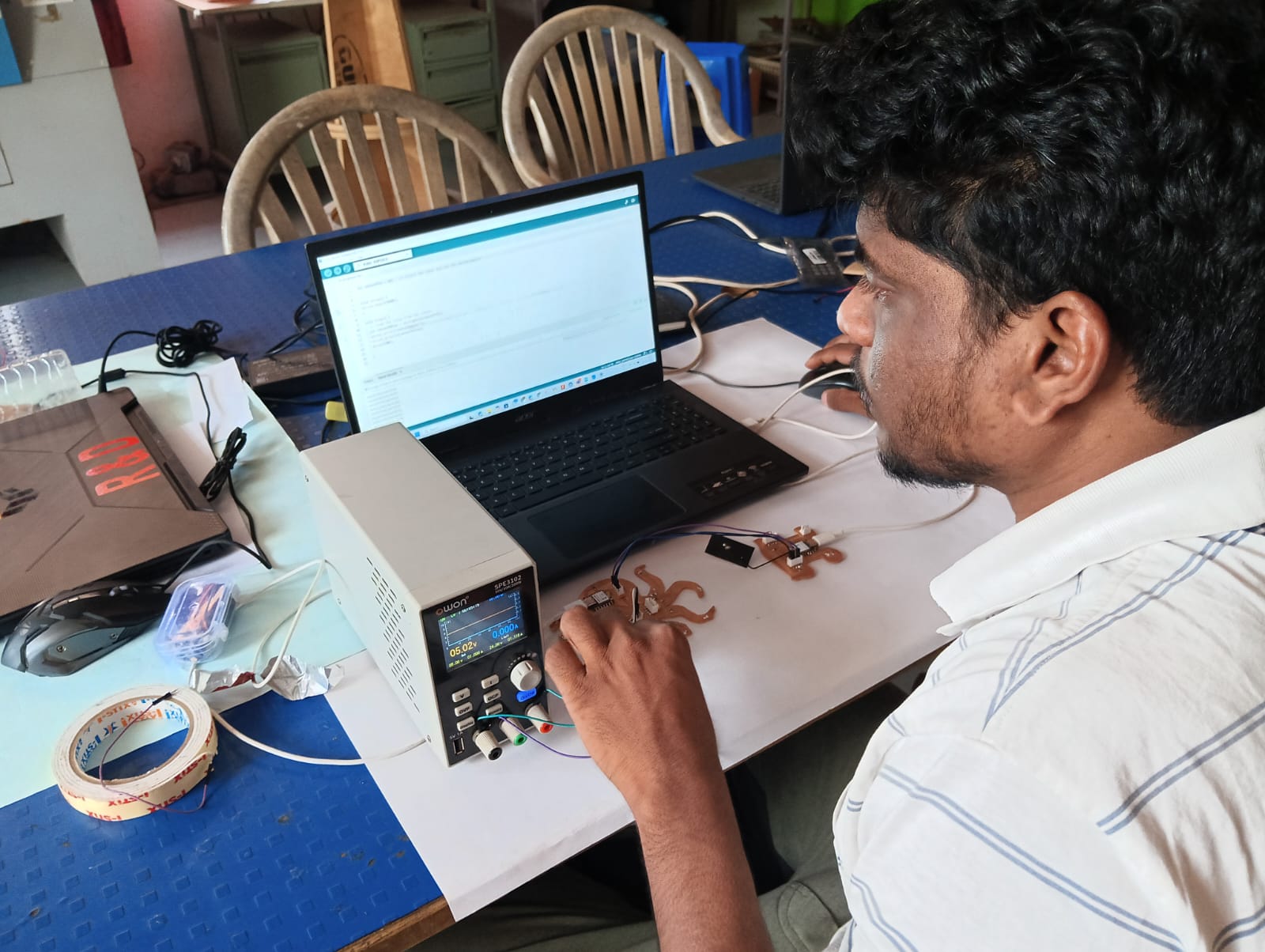
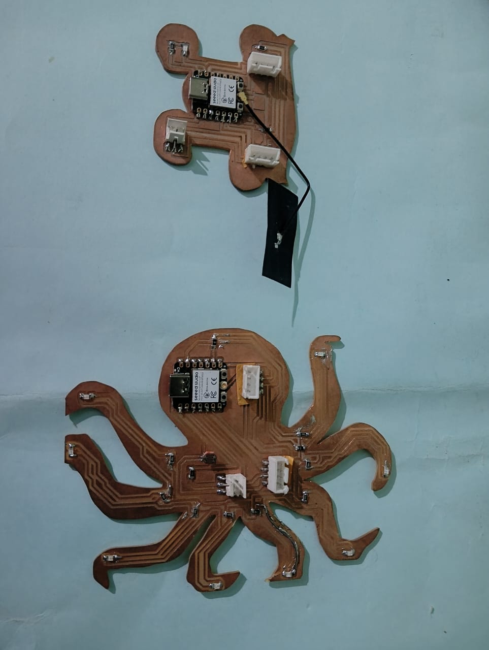
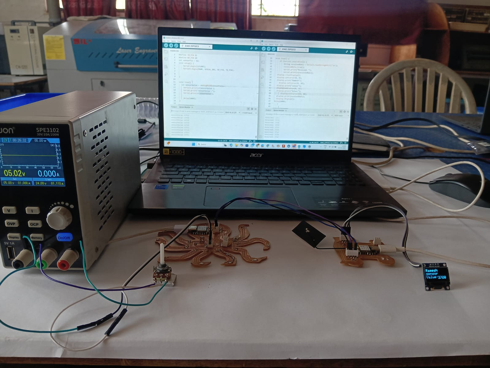
In this communication assignment, I am using the board from my previous assignment. First, I connected two ESP32-C3 boards using serial communication. The TX pin of the first board is connected to the RX pin of the second board, and the RX pin of the first board is connected to the TX pin of the second board. This setup enables two-way serial communication between the two ESP32-C3 boards, as shown below.
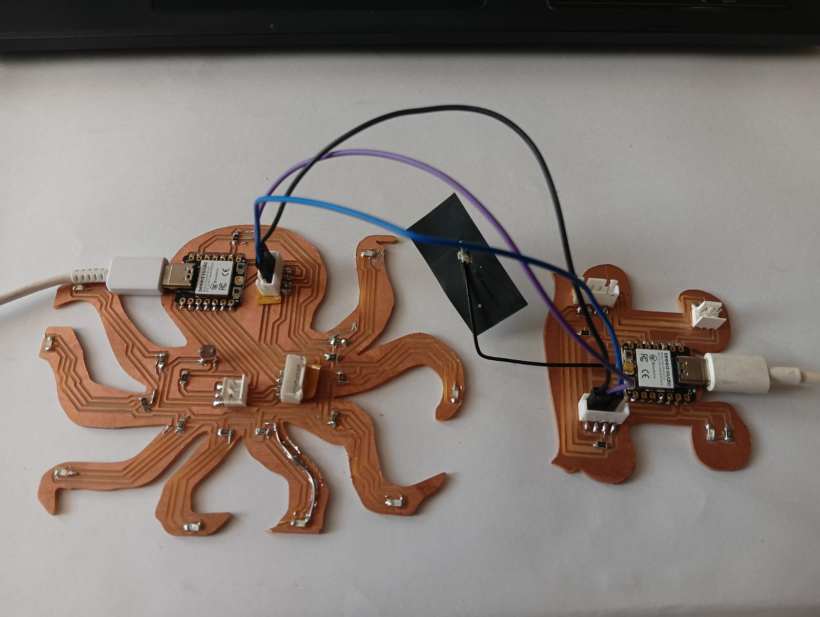
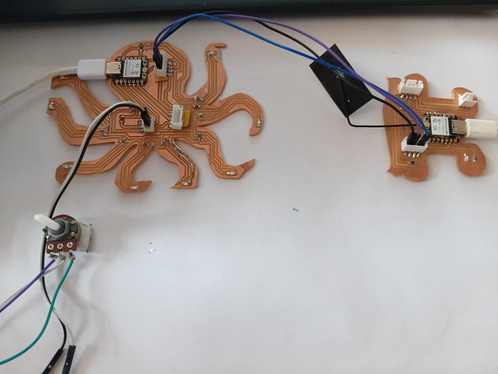
In this communication setup, I am using a potentiometer as the input device. The potentiometer reading from the first ESP32-C3 board is sent to the second board through serial communication. The second board receives the data and displays the value on an OLED display.
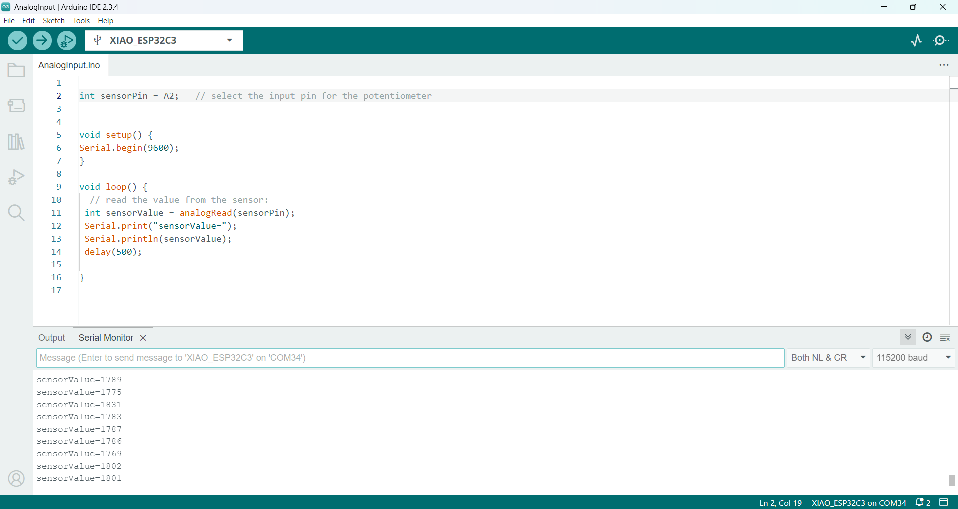
Before setting up the full communication, I first tested the potentiometer with a single ESP32-C3 board to read the analog values. The readings were displayed in the Serial Monitor. The image below shows the setup I used for this testing.
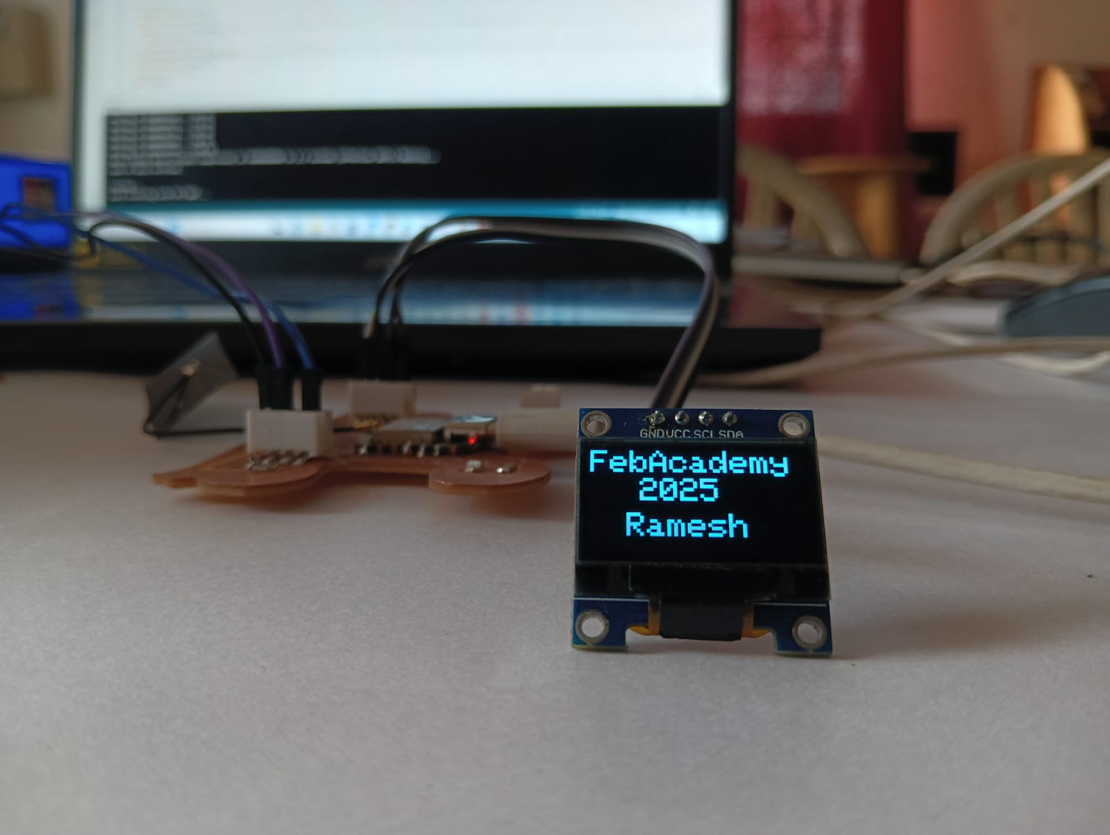
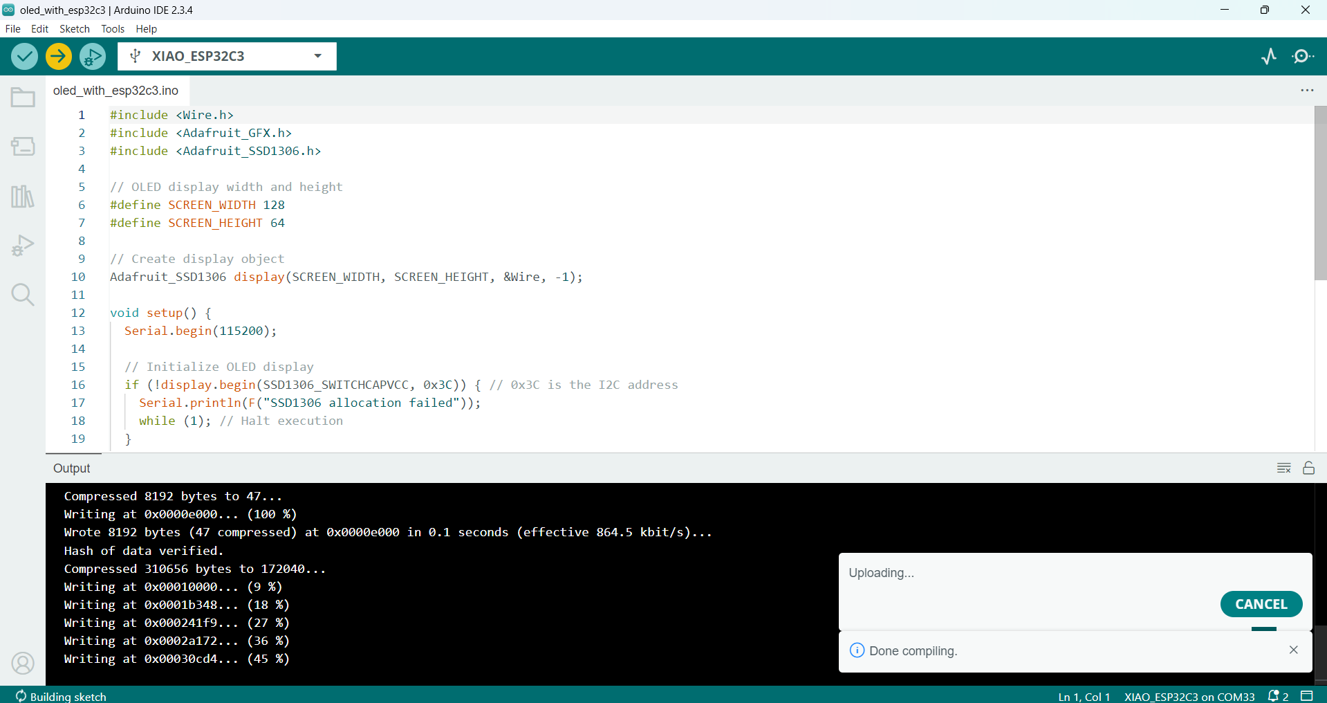
It worked well, so after that, I connected the second ESP32-C3 board to the Arduino IDE and tested whether the OLED display was working properly. For testing, I printed some sample names on the OLED screen. The image below shows the result of this test.
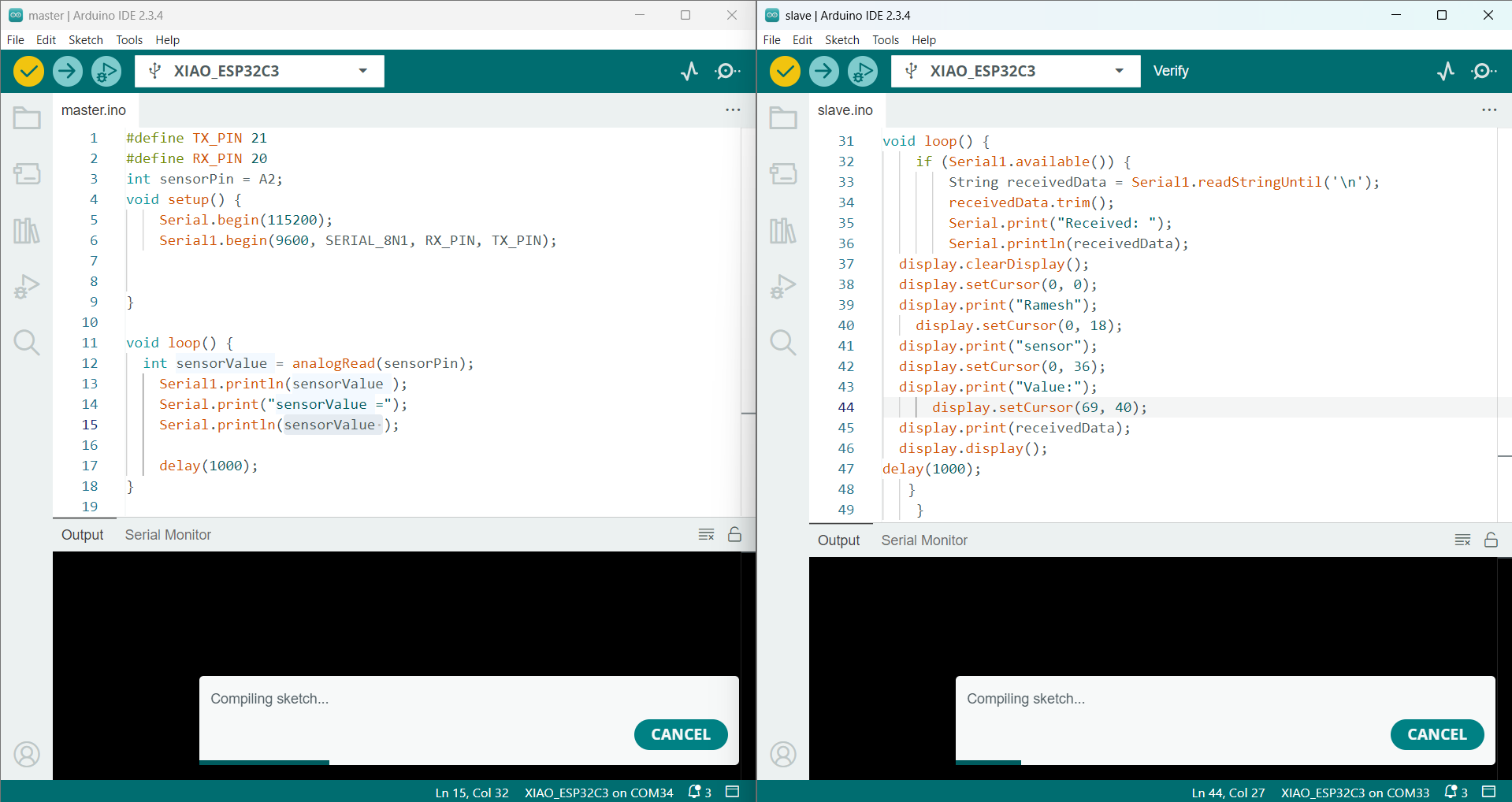
After completing both tests successfully, I started writing the code to enable communication between the two devices using serial communication.
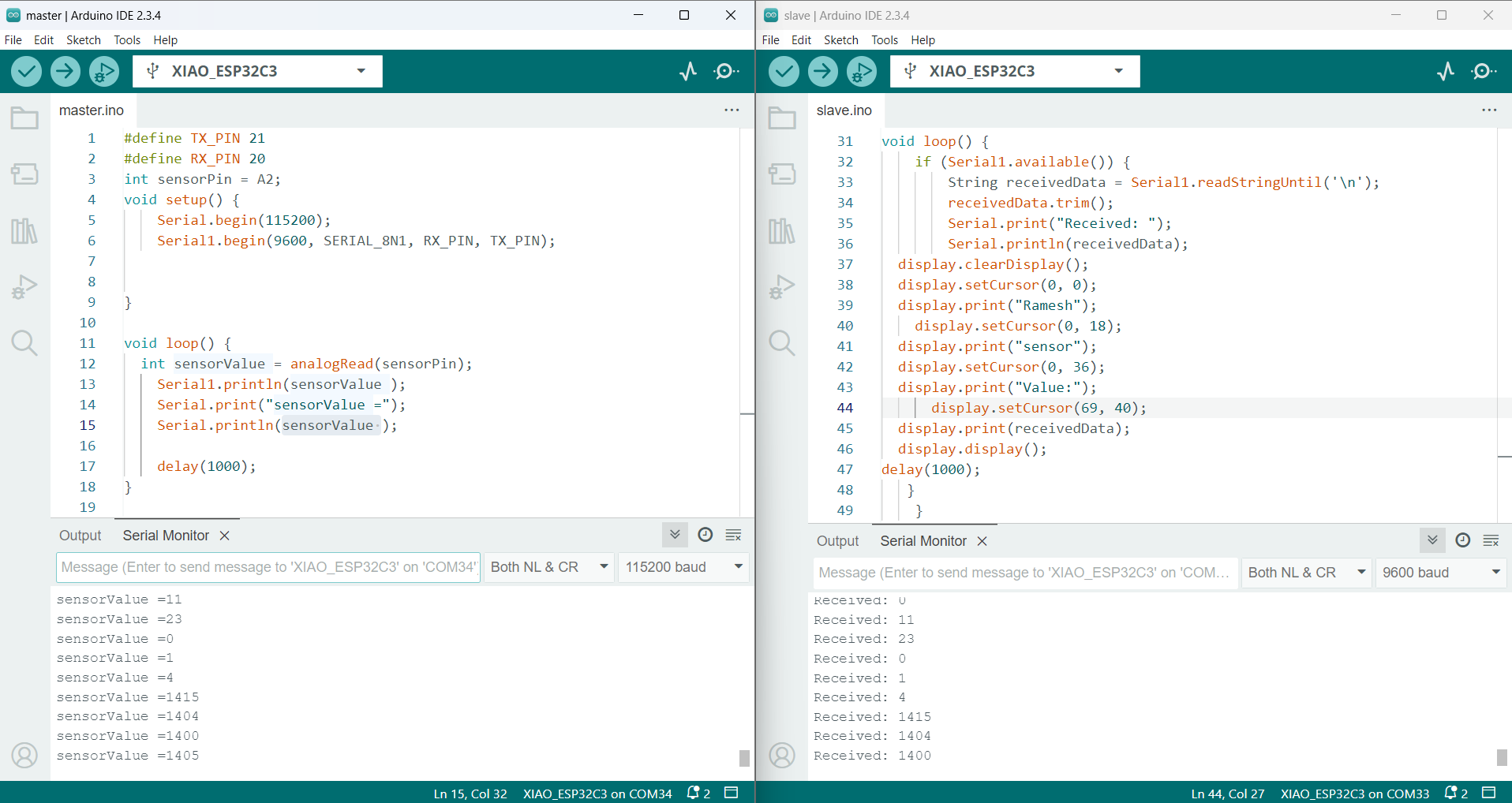
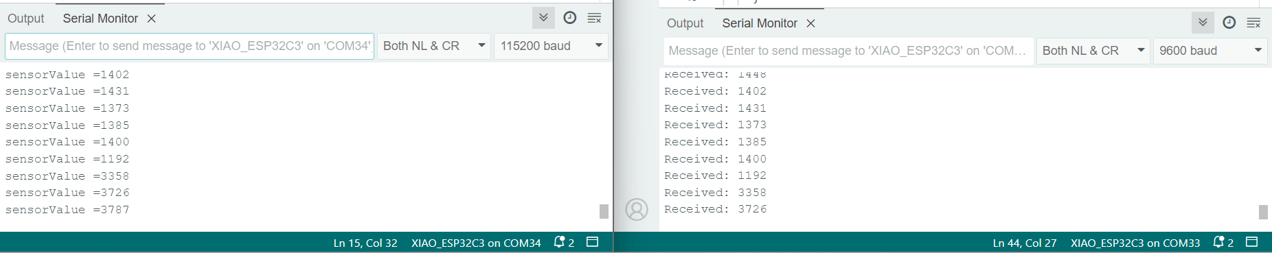
The image below shows the data being sent from the master and printed in the serial monitor of the slave ESP32-C3 board.
Below, I am showing the final working image and the final video of my output.
Arduino Code: Master
// Define UART pins
#define TX_PIN 21
#define RX_PIN 20

#include <Servo.h>

int sensorPin = A2;

void setup() {
    Serial.begin(115200);
    Serial1.begin(9600, SERIAL_8N1, RX_PIN, TX_PIN);
}

void loop() {
    int sensorValue = analogRead(sensorPin);
    Serial1.println(sensorValue);
    Serial.print("sensorValue = ");
    Serial.println(sensorValue);
    delay(1000);
}
Arduino Code: Slave
// Include required libraries
#include <Wire.h>
#include <Adafruit_GFX.h>
#include <Adafruit_SSD1306.h>

#define SCREEN_WIDTH 128
#define SCREEN_HEIGHT 64

// Create display object
Adafruit_SSD1306 display(SCREEN_WIDTH, SCREEN_HEIGHT, &Wire, -1);

#define TX_PIN 21
#define RX_PIN 20

void setup() {
    Serial.begin(115200);
    Serial1.begin(9600, SERIAL_8N1, RX_PIN, TX_PIN);

    if (!display.begin(SSD1306_SWITCHCAPVCC, 0x3C)) { // 0x3C is the I2C address
        Serial.println(F("SSD1306 allocation failed"));
        while (1);
    }

    display.clearDisplay();
    display.setTextSize(2);
    display.setTextColor(SSD1306_WHITE);
    delay(100);
}

void loop() {
    if (Serial1.available()) {
        String receivedData = Serial1.readStringUntil('\n');
        receivedData.trim();

        Serial.print("Received: ");
        Serial.println(receivedData);

        display.clearDisplay();
        display.setCursor(0, 0);
        display.print("Ramesh");
        display.setCursor(0, 18);
        display.print("sensor");
        display.setCursor(0, 36);
        display.print("Value:");
        display.setCursor(69, 40);
        display.print(receivedData);
        display.display();

        delay(1000);
    }
}
2.ESP-NOW wireless communication :
After completing the first communication, I also tested ESP-NOW wireless communication, which I have already explained above. In this setup, I used one-way communication by sending the data from the transmitter to the receiver using the receiver's MAC address over Wi-Fi.
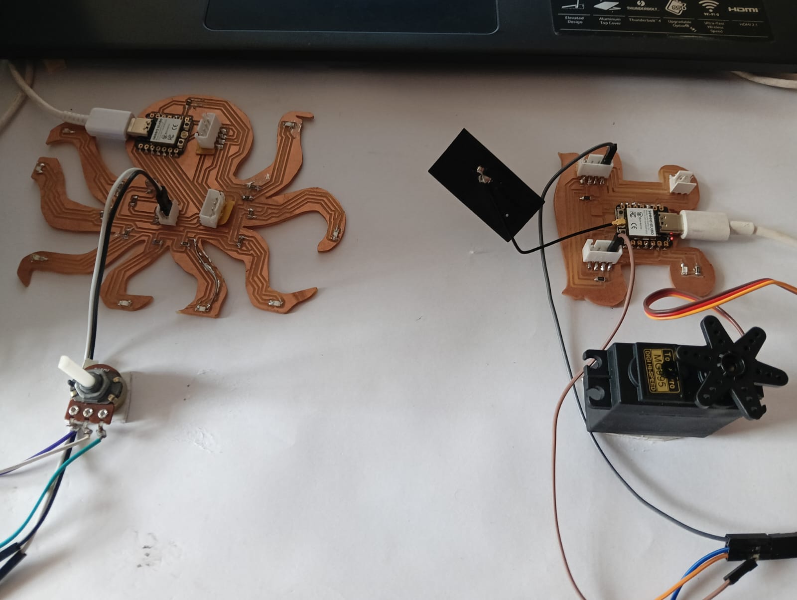
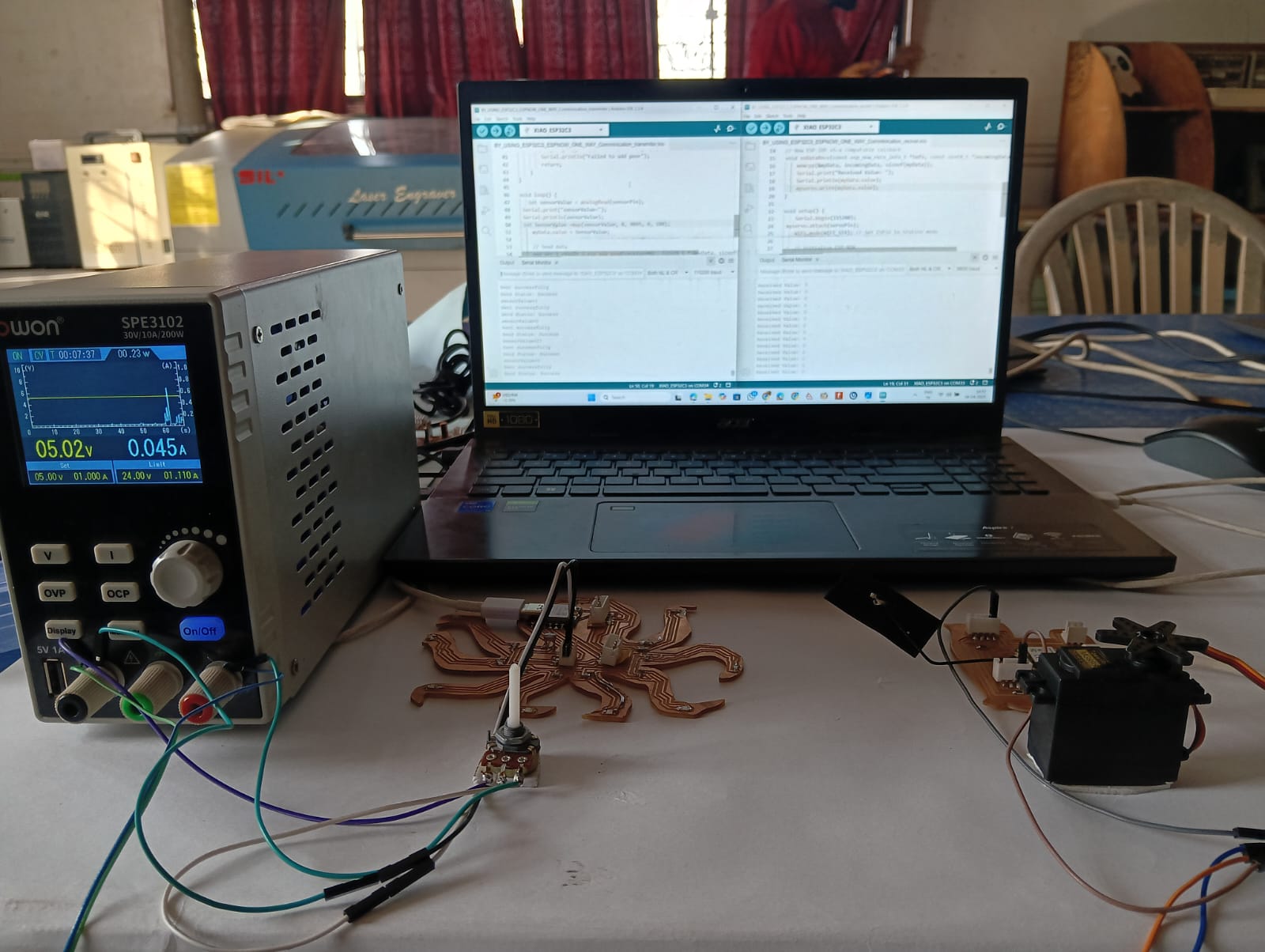
For setting up this communication, I used a potentiometer as the input on the transmitter side. The potentiometer reading was sent to the receiver using ESP-NOW, and based on this reading, a servo motor was controlled on the receiver module. The image below shows the setup and working connection.
Before moving forward with the full process, I had already tested the potentiometer readings in a previous task. Now, I tested running the servo motor using the ESP32-C3 to ensure everything works smoothly for the next steps. The image below shows the test setup and output.
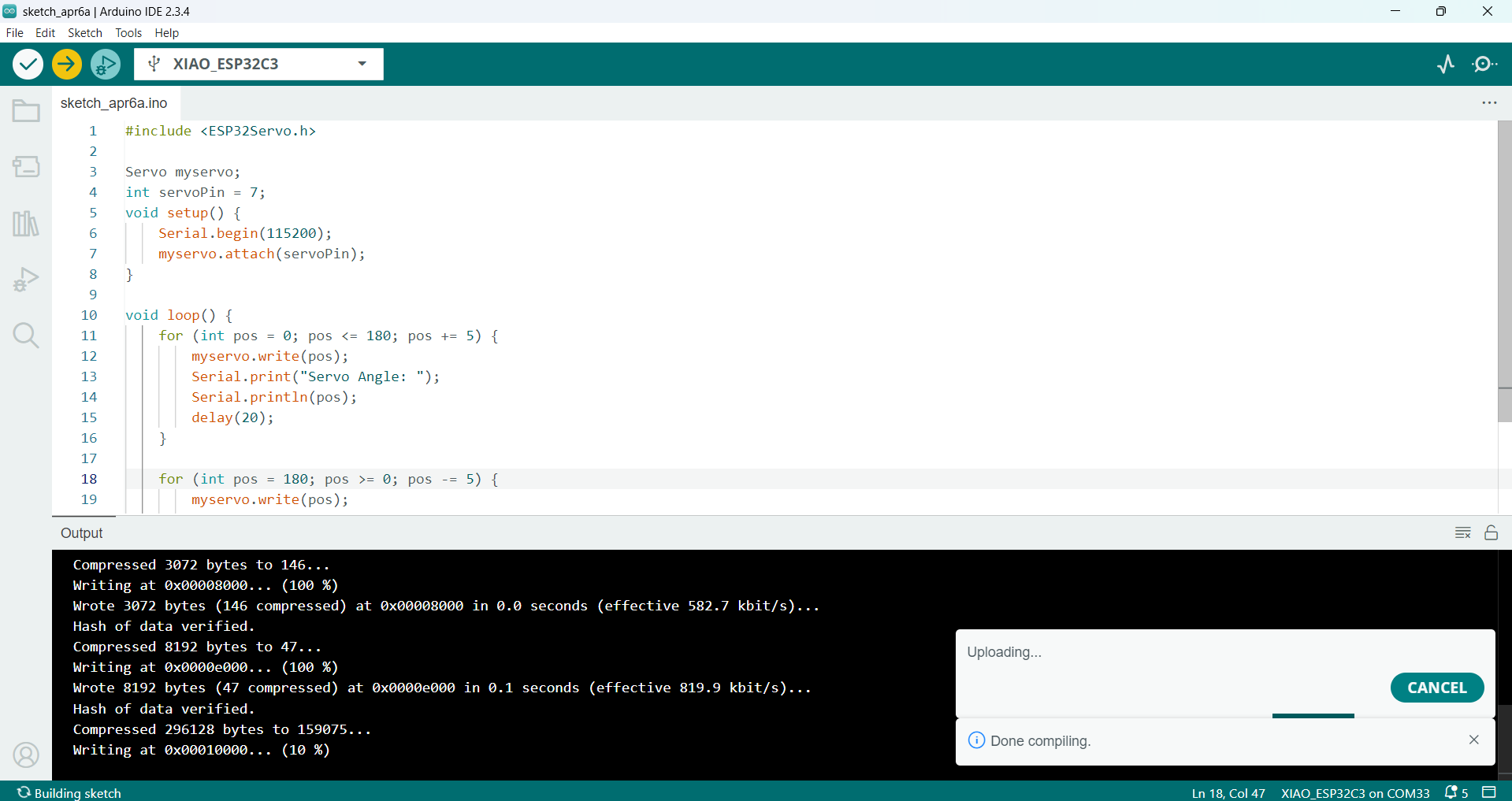
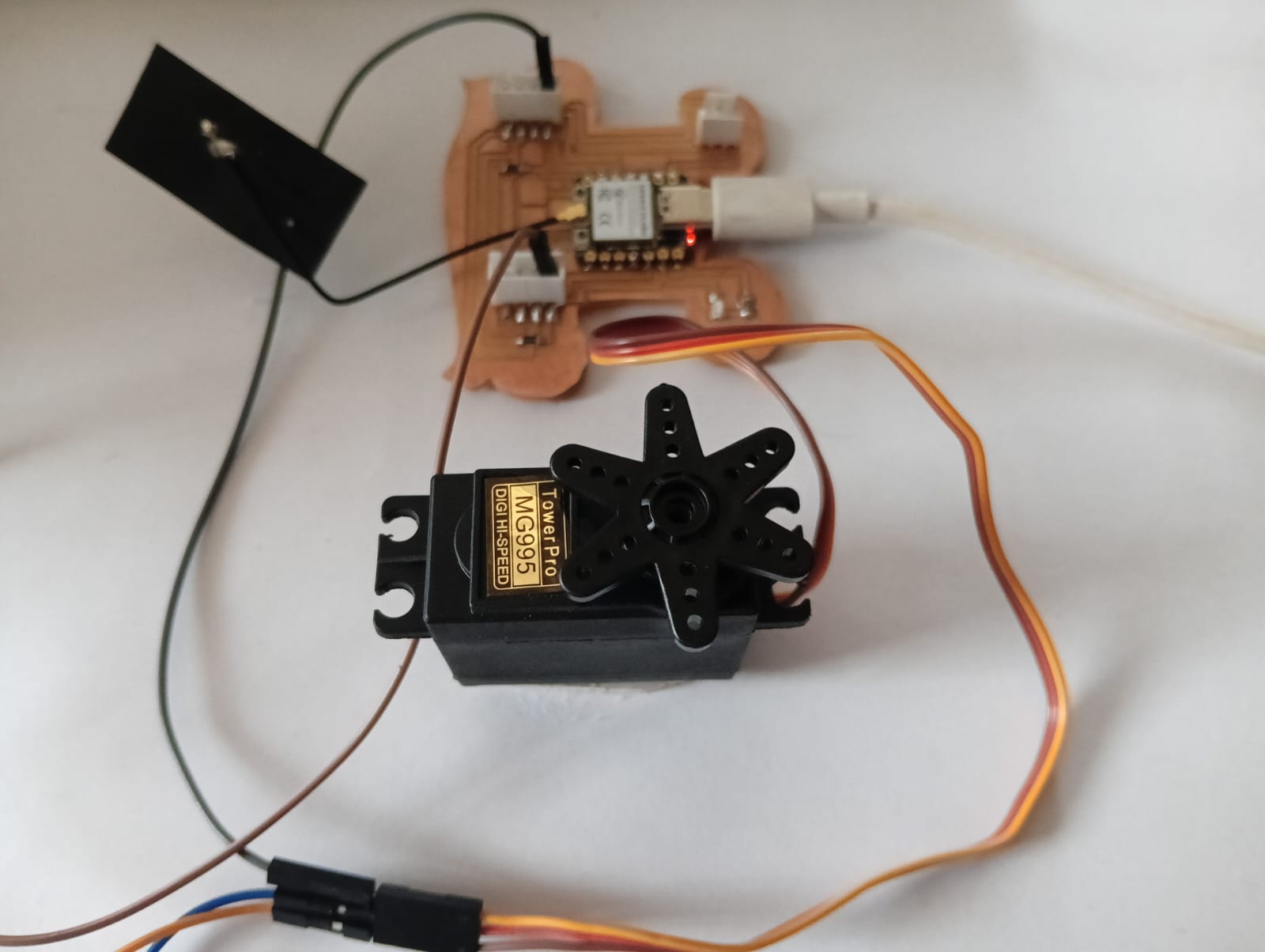
Below, I am showing the working of the servo motor with the ESP32-C3.
After successfully running the servo motor, I continued with the next step. I found the MAC address of my receiver ESP32-C3 board, which is required for establishing ESP-NOW communication. Below, I am showing the code used to find the MAC address.
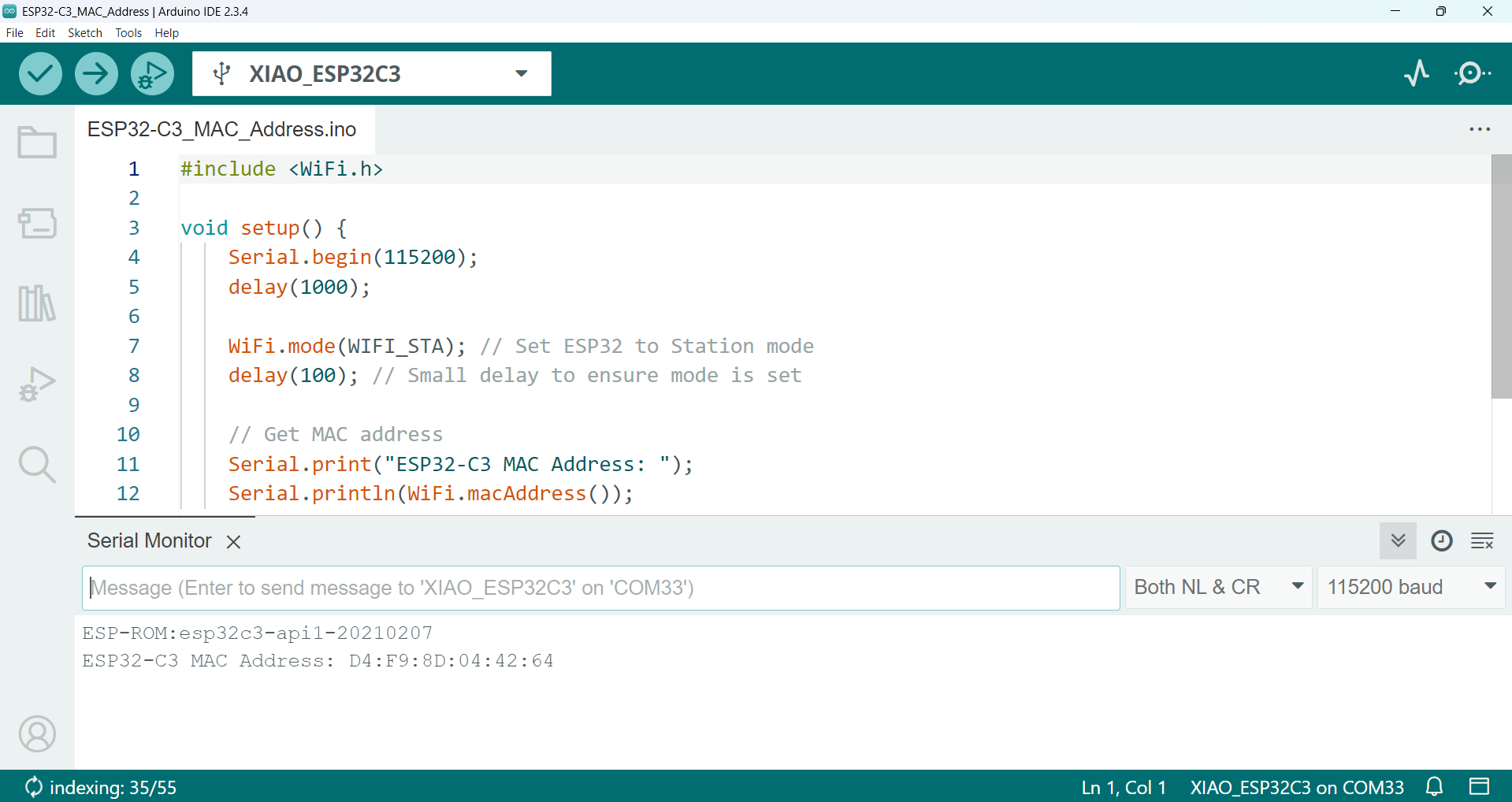
Arduino Code: Finding MAC Address for ESP32-C3
// Include WiFi library
#include <WiFi.h>

void setup() {
    Serial.begin(115200);
    delay(1000);

    WiFi.mode(WIFI_STA); // Set ESP32 to Station mode
    delay(100); // Small delay to ensure mode is set

    // Get MAC address
    Serial.print("ESP32-C3 MAC Address: ");
    Serial.println(WiFi.macAddress());
}

void loop() {
    // Do nothing
}
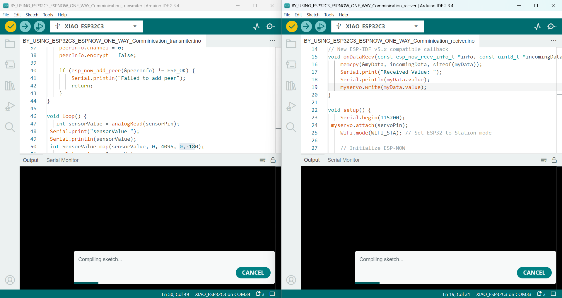
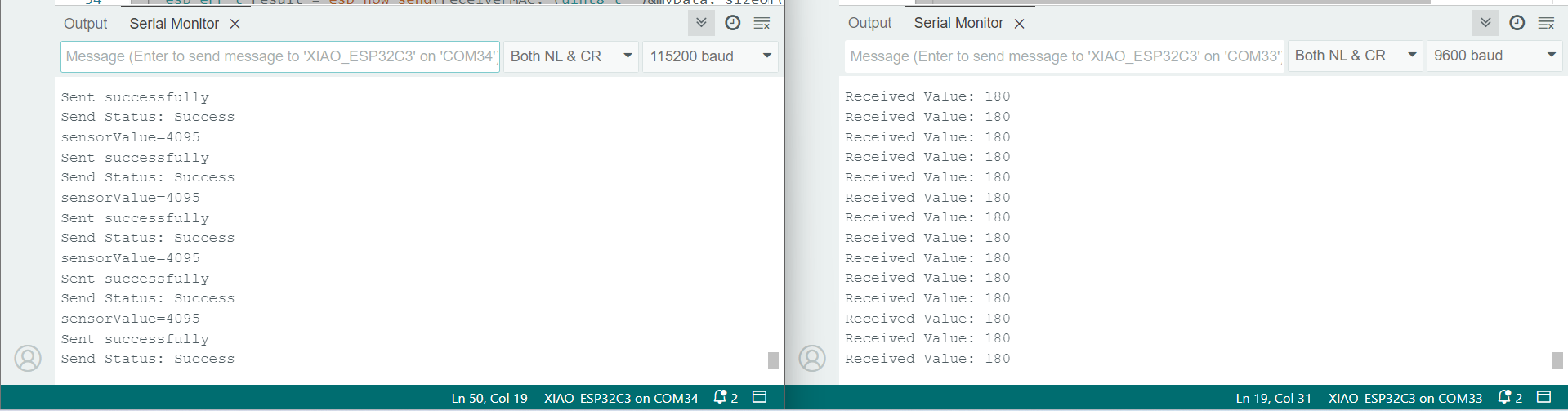
After retrieving the MAC address of my receiver board, I started the communication between the two ESP32-C3 devices. I sent the potentiometer values from the transmitter and mapped those values to corresponding servo angles to ensure the servo motor runs smoothly. The sketch uploading and the received data are shown below.
Below, I am showing the data received from the transmitter. The receiver ESP32-C3 displays the incoming potentiometer values in the serial monitor.
Below, I am showing the final working of this task. The complete communication setup successfully controls the servo motor based on the potentiometer input.
Arduino Code: Transmitter Sketch
                // Include necessary libraries
                #include <WiFi.h>
                #include <esp_now.h>

                int sensorPin = A2;

                // Replace with the actual MAC address of the receiver
                uint8_t receiverMAC[] = {0xD4, 0xF9, 0x8D, 0x04, 0x42, 0x64};

                // Define the structure for the data to be sent
                typedef struct struct_message {
                    int value;
                } struct_message;

                struct_message myData;

                // Callback function on data sent
                void onDataSent(const uint8_t *mac_addr, esp_now_send_status_t status) {
                    Serial.print("Send Status: ");
                    Serial.println(status == ESP_NOW_SEND_SUCCESS ? "Success" : "Fail");
                }

                void setup() {
                    Serial.begin(115200);

                    WiFi.mode(WIFI_STA); // Set ESP32 to Station mode

                    // Initialize ESP-NOW
                    if (esp_now_init() != ESP_OK) {
                        Serial.println("ESP-NOW Init Failed!");
                        return;
                    }

                    esp_now_register_send_cb(onDataSent);

                    // Register peer
                    esp_now_peer_info_t peerInfo = {};
                    memcpy(peerInfo.peer_addr, receiverMAC, 6);
                    peerInfo.channel = 0;
                    peerInfo.encrypt = false;

                    if (esp_now_add_peer(&peerInfo) != ESP_OK) {
                        Serial.println("Failed to add peer");
                        return;
                    }
                }

                void loop() {
                    int sensorValue = analogRead(sensorPin);
                    Serial.print("sensorValue = ");
                    Serial.println(sensorValue);

                    int mappedValue = map(sensorValue, 0, 4095, 0, 180);
                    myData.value = mappedValue;

                    // Send data
                    esp_err_t result = esp_now_send(receiverMAC, (uint8_t *)&myData, sizeof(myData));

                    if (result == ESP_OK) {
                        Serial.println("Sent successfully");
                    } else {
                        Serial.println("Error sending data");
                    }

                    delay(200); // Delay before next send
                }
Arduino Code: Receiver Sketch
                #include <WiFi.h>
                #include <esp_now.h>
                #include <ESP32Servo.h>

                Servo myservo;
                int servoPin = 7;

                // Structure to receive data
                typedef struct struct_message {
                    int value;
                } struct_message;

                struct_message myData;

                // Callback function when data is received
                void onDataRecv(const esp_now_recv_info_t *info, const uint8_t *incomingData, int len) {
                    memcpy(&myData, incomingData, sizeof(myData));
                    Serial.print("Received Value: ");
                    Serial.println(myData.value);
                    myservo.write(myData.value);
                }

                void setup() {
                    Serial.begin(115200);
                    myservo.attach(servoPin);
                    WiFi.mode(WIFI_STA); // Set ESP32 to Station mode

                    // Initialize ESP-NOW
                    if (esp_now_init() != ESP_OK) {
                        Serial.println("ESP-NOW Init Failed!");
                        return;
                    }

                    // Register receive callback
                    esp_now_register_recv_cb(onDataRecv);
                }

                void loop() {
                    // Waiting for ESP-NOW messages
                }
3. Wi-Fi Communication by using ThingSpeak for IoT Connectivity:
After successfully completing two types of communication—serial communication between two ESP32-C3 boards and wireless communication using ESP-NOW—I am now progressing to IoT-based communication. For this purpose, I will be using the ThingSpeak platform provided by Verizon. This platform allows real-time monitoring and visualization of sensor readings over the internet. It will help in expanding the project towards remote data access and smart monitoring applications.
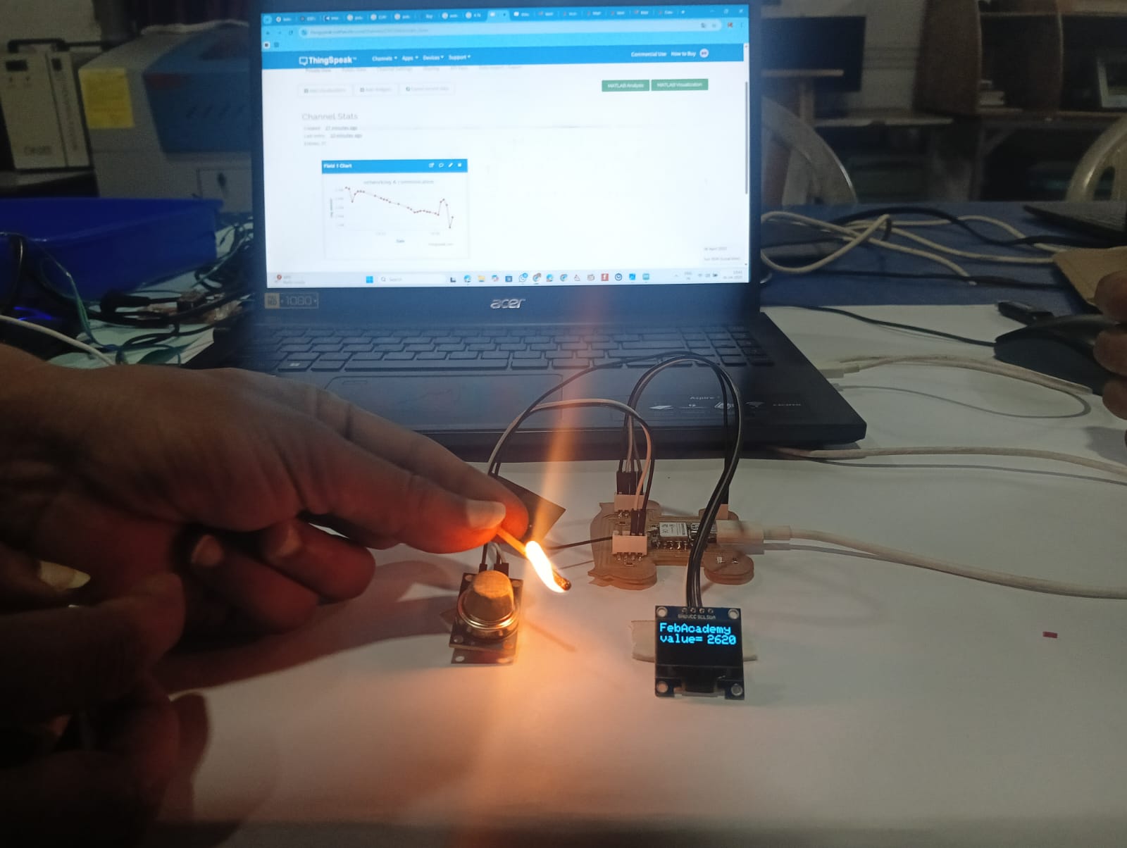
For this communication, you are using the MQ-6 gas sensor to monitor gas levels. The readings from the MQ-6 sensor are sent through the ESP32-C3, which transmits the data to the ThingSpeak platform for monitoring. This allows real-time tracking of gas concentrations on the platform.
Before going to the programming part, I will first explain how I set up the ThingSpeak dashboard for monitoring the values.
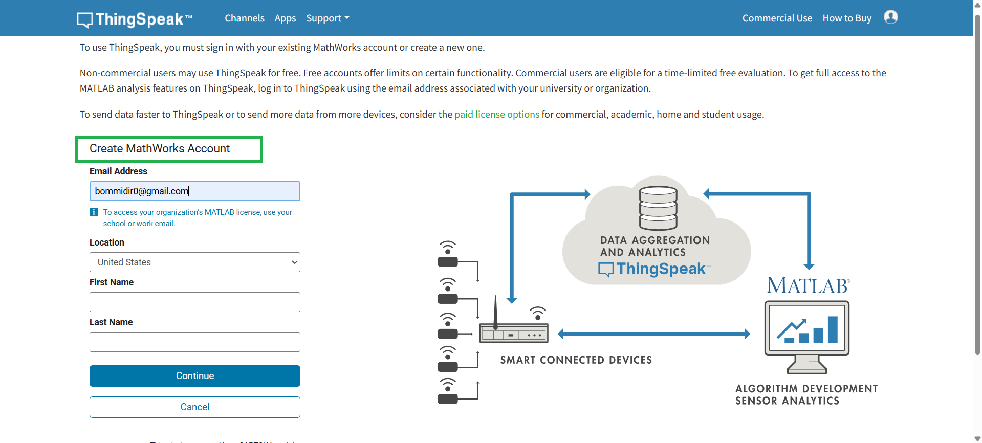
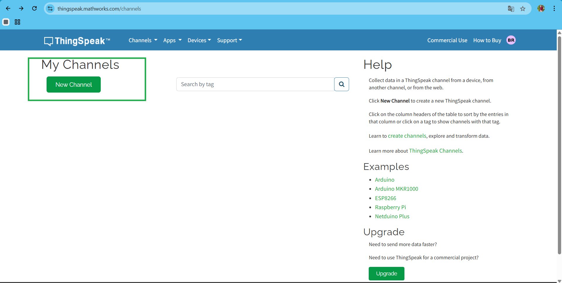
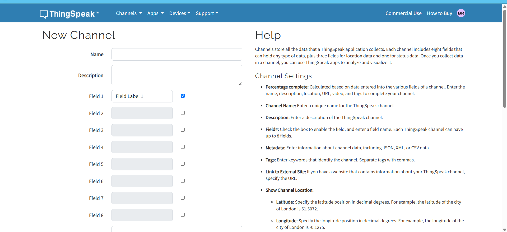
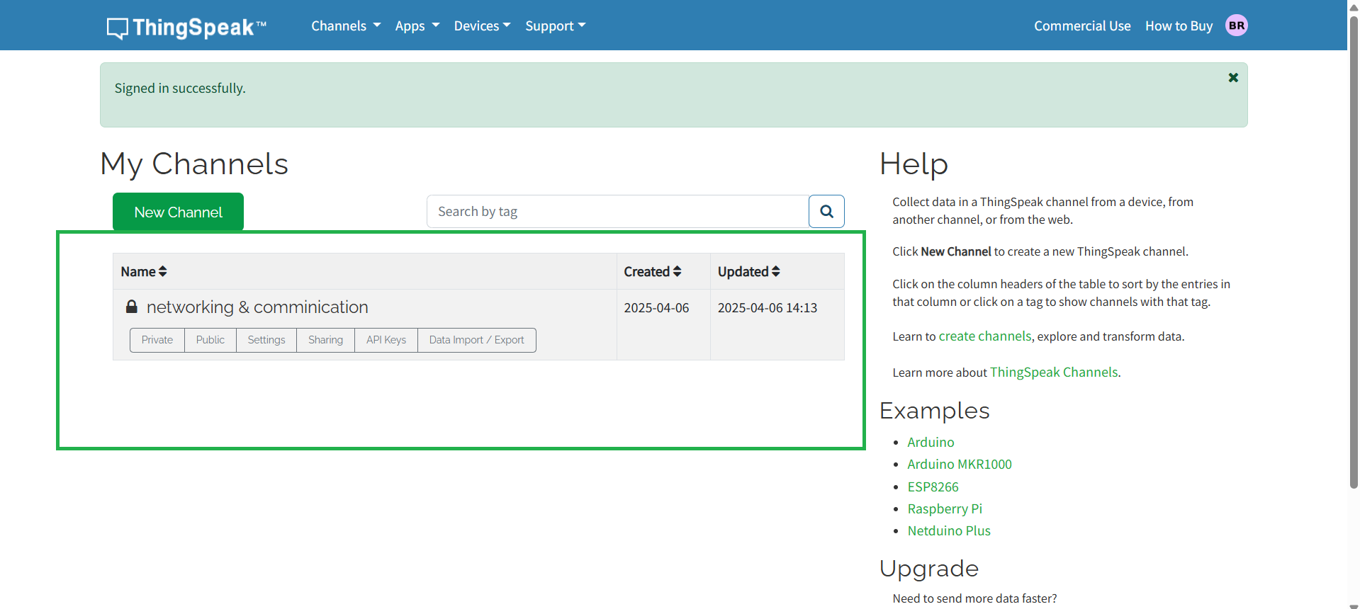
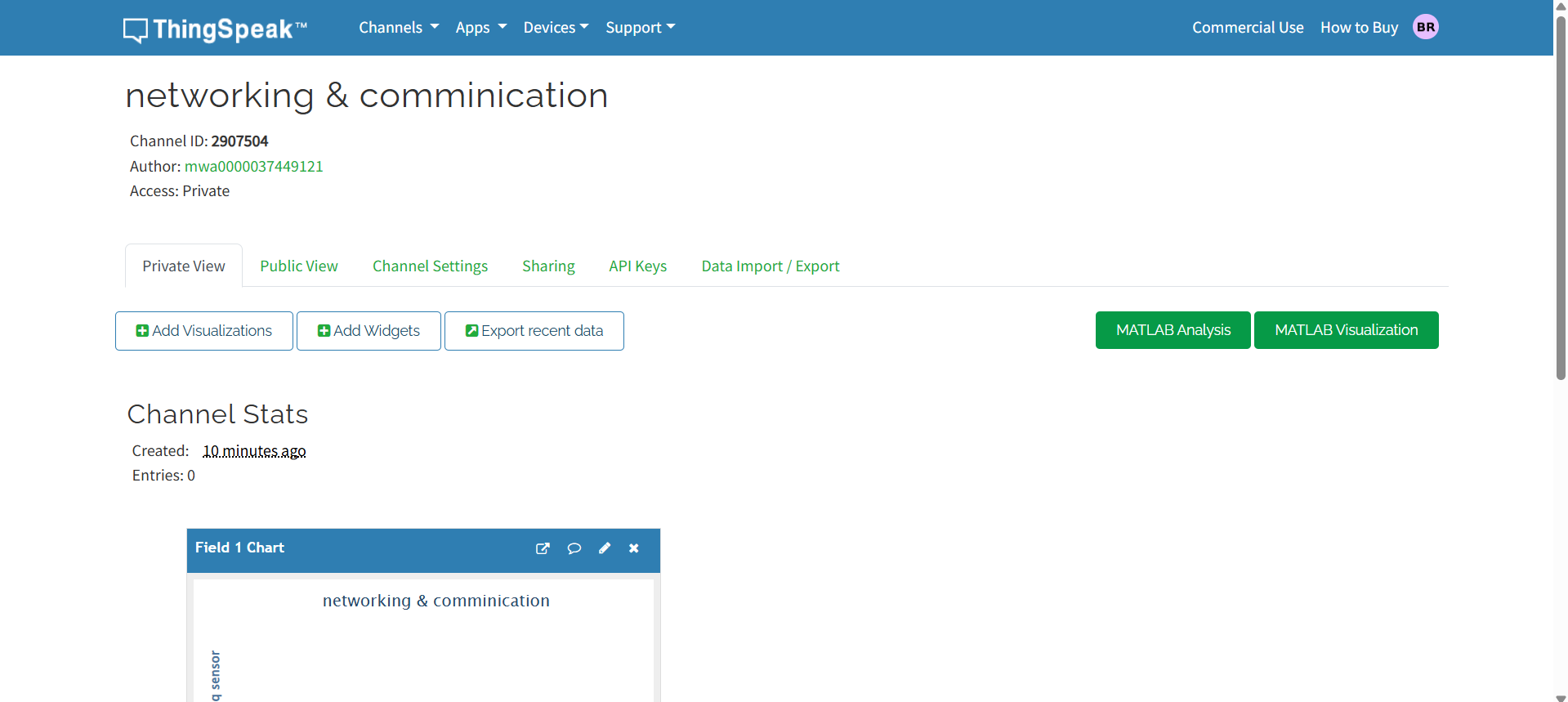
First, I created my account on the ThingSpeak website. Click here to create an account. After creating the account, I created a new channel for my sensor. I am showing the setup in the image below.
After creating the account and channel, the website automatically generates an API key. Using this key, I can communicate with the ThingSpeak website. Below, I am showing where the API key is located.
After generating the API key, I began writing the code for my board. This code enables the board to connect to the ThingSpeak platform and send sensor data using the API key, allowing real-time monitoring of the values online.
In this communication setup, I am also using an OLED display to show the sensor readings. Below, I am showing the setup of my board.
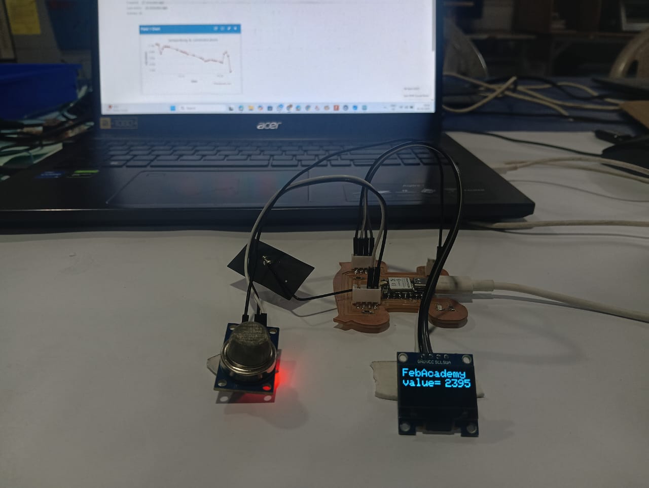
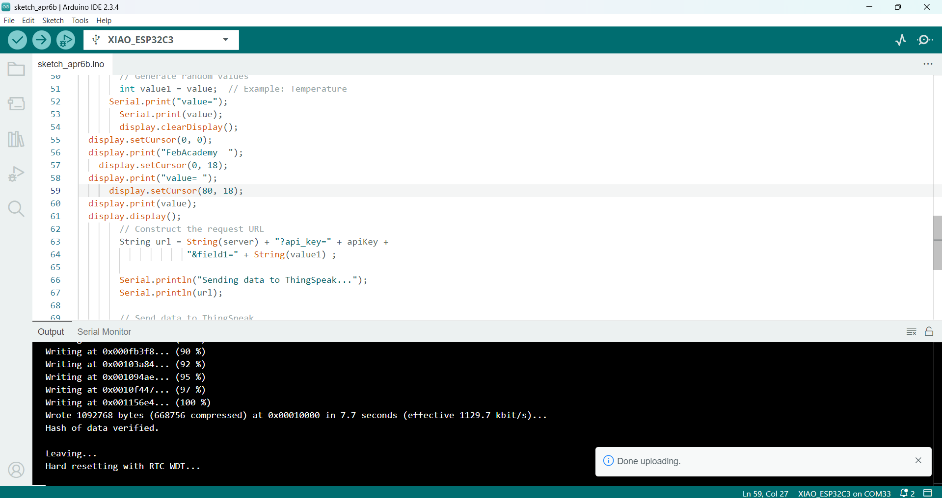
After uploading the code to my board, everything worked well. Below, I am showing the working of my project. The sensor readings are displayed on the OLED screen in real-time, allowing for local monitoring. At the same time, the data is sent to the ThingSpeak dashboard using the API key, enabling remote monitoring through the internet
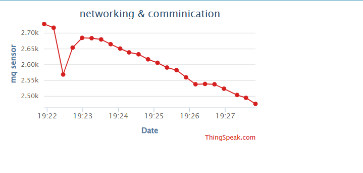
Below, I am showing the ThingSpeak dashboard, which I use to monitor the values. The values change in real-time according to the sensor readings.
Arduino Code: ThingSpeak for IoT Connectivity
#include <WiFi.h>
#include <HTTPClient.h>
#include <Wire.h>
#include <Adafruit_GFX.h>
#include <Adafruit_SSD1306.h>

int sensor = A0;
const char* ssid = "FABLAB";
const char* password = "12345678";
const char* apiKey = "UM9X89DM281G61EI";
const char* server = "http://api.thingspeak.com/update";

#define SCREEN_WIDTH 128
#define SCREEN_HEIGHT 64
Adafruit_SSD1306 display(SCREEN_WIDTH, SCREEN_HEIGHT, &Wire, -1);

void setup() {
  Serial.begin(115200);
  WiFi.begin(ssid, password);

  Serial.print("Connecting to WiFi...");
  while (WiFi.status() != WL_CONNECTED) {
    Serial.print(".");
    delay(500);
  }
  Serial.println("\nConnected to WiFi!");

  if (!display.begin(SSD1306_SWITCHCAPVCC, 0x3C)) {
    Serial.println(F("SSD1306 allocation failed"));
    while (1);
  }

  display.clearDisplay();
  display.setTextSize(2);
  display.setTextColor(SSD1306_WHITE);
  delay(100);
}

void loop() {
  if (WiFi.status() == WL_CONNECTED) {
    HTTPClient http;
    int value = analogRead(sensor);
    int value1 = value;

    Serial.print("value=");
    Serial.println(value);

    display.clearDisplay();
    display.setCursor(0, 0);
    display.print("FebAcademy  ");
    display.setCursor(0, 18);
    display.print("value= ");
    display.setCursor(80, 18);
    display.print(value);
    display.display();

    String url = String(server) + "?api_key=" + apiKey + "&field1=" + String(value1);

    Serial.println("Sending data to ThingSpeak...");
    Serial.println(url);

    http.begin(url);
    int httpCode = http.GET();

    if (httpCode > 0) {
      Serial.println("Data sent successfully!");
    } else {
      Serial.println("Failed to send data.");
    }

    http.end();
  } else {
    Serial.println("WiFi Disconnected!");
  }

  delay(15000); // ThingSpeak allows updates every 15 seconds
}
Positive Outcomes:
This week’s assignment helped me learn about different types of communication methods, both wired and wireless. I had the opportunity to experience some of these communication techniques in practice, which made the learning process more engaging. I especially enjoyed working with wireless communication—it was fascinating to see how accurately it worked. I was genuinely surprised that data could be transmitted without using any physical wires. Seeing this in action gave me a deeper appreciation for the technology. The success of the wireless setup boosted my confidence and made me eager to explore more advanced communication protocols. Overall, it was a fun, exciting, and highly educational experience.
Challenges Encountered:
I didn’t face major challenges, but I was confused about how to connect two boards for wired communication. I wasn’t sure how to send data using serial communication between them. Another challenge was finding the MAC address of the ESP32-C3 board. These issues took some time to understand, but I learned a lot through the process.