During this assignment, I gained a valuable learning experience. I worked with all three types of communication – wired, WiFi and cloud. I learned how to transfer data between microcontrollers, how to use sensors like voltage and current sensors and how to connect my project to the internet using ThingSpeak. I also gained practical experience with tools like Arduino IDE, Serial Monitor and ESP32 boards. I was able to debug my code more efficiently and reduce errors. This helped me improve my understanding of communication protocols and increase my confidence in embedded system development. Along with this, I have also prepared half of the code for my final project which was a success for me.
Key Accomplishments
✅ Completed tests and final code for wired communication.
✅ Successfully implemented data transfer using WiFi (ESP-NOW).
✅ Connected IoT devices to ThingSpeak cloud platform and visualized the data.
✅ Integrated voltage and current sensors into my communication setup.
✅ Completed 50% of my final project code.
Document your work to the group work page and reflect on your individual page what you learned
Individual project:
design, build and connect wired or wireless node(s) with network or bus addresses and a local input and/or output devices
Individual Assignment:
For this assignment, I have decided to start by learning how to use LCD/OLED displays, voltage sensors, and current sensors. I will explore both wired and wireless communication, including IoT methods. I will also learn how to calculate power (in watts) using voltage and current, which will help me in my final project.
Embedded Networking and Communications
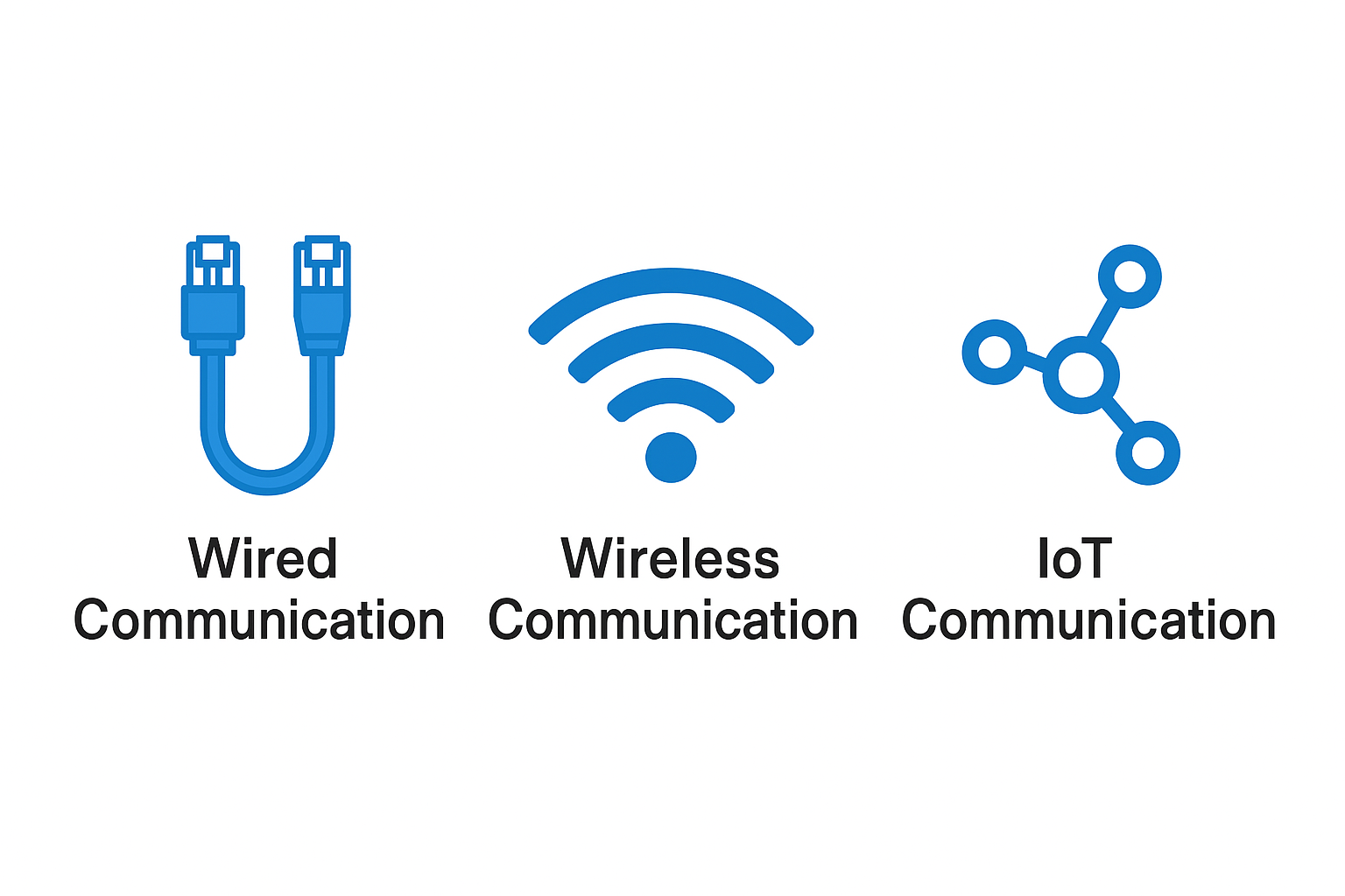
Embedded networking uses protocols like Wi-Fi, Bluetooth, I2C, and UART to help small devices—such as sensors and smart gadgets—share data. It powers smart systems in homes, businesses, and the Internet of Things (IoT). These systems need both hardware and software knowledge and must work fast, safely, and with low power. Embedded networking enables real-time communication between devices, making our lives smarter and more convenient.
Wire Communication
In embedded systems, wired communication means transferring data between devices using physical wires. Common protocols include UART, I2C, and SPI.
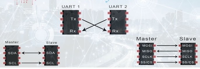
UART (Universal Asynchronous Receiver/Transmitter) uses two wires — TX (Transmit) and RX (Receive) — to connect microcontrollers with computers or Bluetooth modules.
I2C (Inter-Integrated Circuit) uses two wires — SDA (Data) and SCL (Clock) — to connect multiple devices like sensors and displays. Each device has a unique address.
SPI (Serial Peripheral Interface) is faster and uses four wires — MOSI (Master Out Slave In), MISO (Master In Slave Out), SCK (Clock), and SS (Slave Select). It’s often used with high-speed devices like SD cards.
Protocol
Speed
Main Use
Example
USB (Universal Serial Bus)
High
Transferring data and charging devices
Connecting Arduino to a computer using USB
Ethernet (LAN)
Very fast (up to 10 Gbps or more)
Internet access and sharing data between computers
Office computers connected to a router with Ethernet cables
SPI (Serial Peripheral Interface)
Very fast
Connecting microcontrollers to sensors, displays, or SD cards
Arduino connected to an OLED display using SPI
I2C (Inter-Integrated Circuit)
Moderate
Connecting multiple devices using fewer wires
Arduino connected to temperature and humidity sensors using I2C
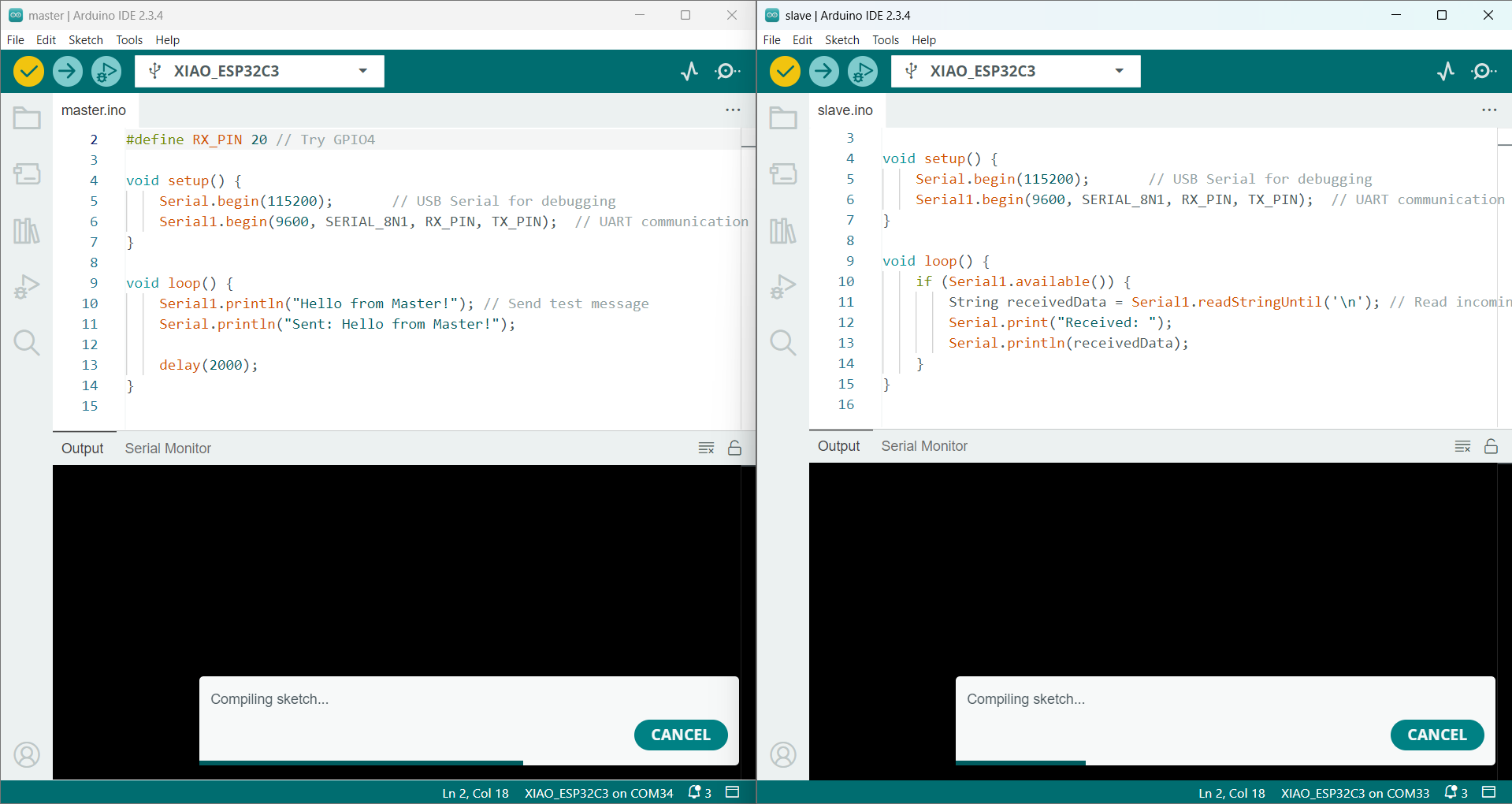
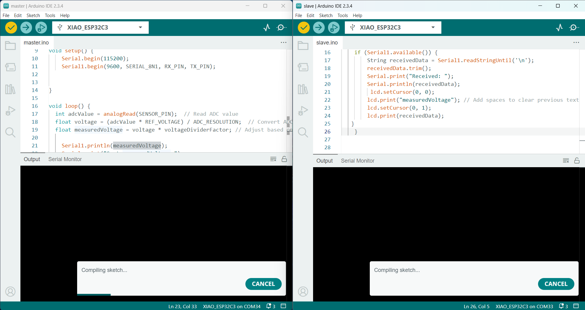
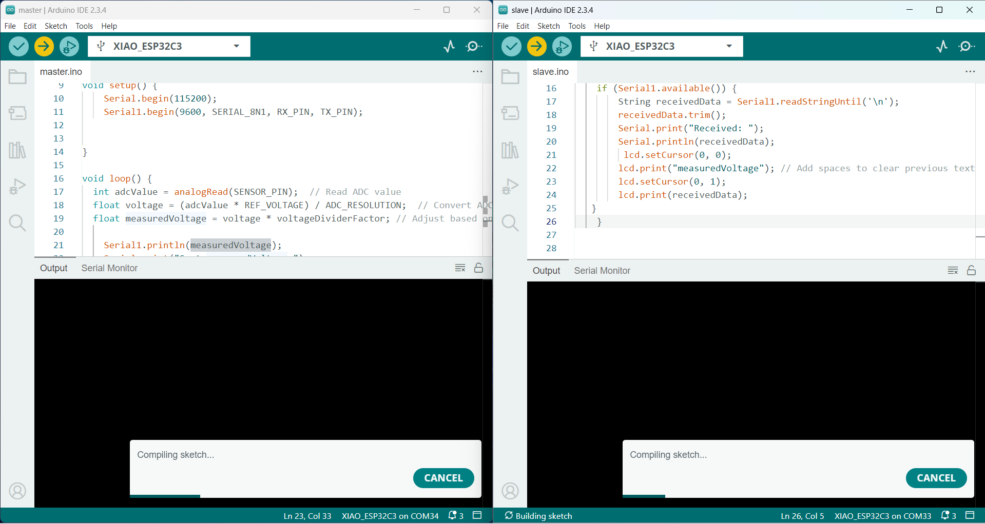
To transfer data between two boards, we need two separate programs — one for the sender and one for the receiver. We demonstrated this in our group assignment. The codes for both boards are provided below.
Testing Master Code
#define TX_PIN 5  // GPIO5 for TX
#define RX_PIN 4  // GPIO4 for RX

void setup() {
    Serial.begin(115200);       // USB Serial for debugging
    Serial1.begin(9600, SERIAL_8N1, RX_PIN, TX_PIN);  // UART communication
}

void loop() {
    Serial1.println("Hello from Master!"); // Send test message
    Serial.println("Sent: Hello from Master!");

    delay(2000);
}
Testing Slave Code
#define TX_PIN 5  // GPIO5 for TX
#define RX_PIN 4  // GPIO4 for RX

void setup() {
    Serial.begin(115200);       // USB Serial for debugging
    Serial1.begin(9600, SERIAL_8N1, RX_PIN, TX_PIN);  // UART communication
}

void loop() {
    if (Serial1.available()) {
        String received = Serial1.readStringUntil('\n');
        Serial.print("Received: ");
        Serial.println(received);
    }
}
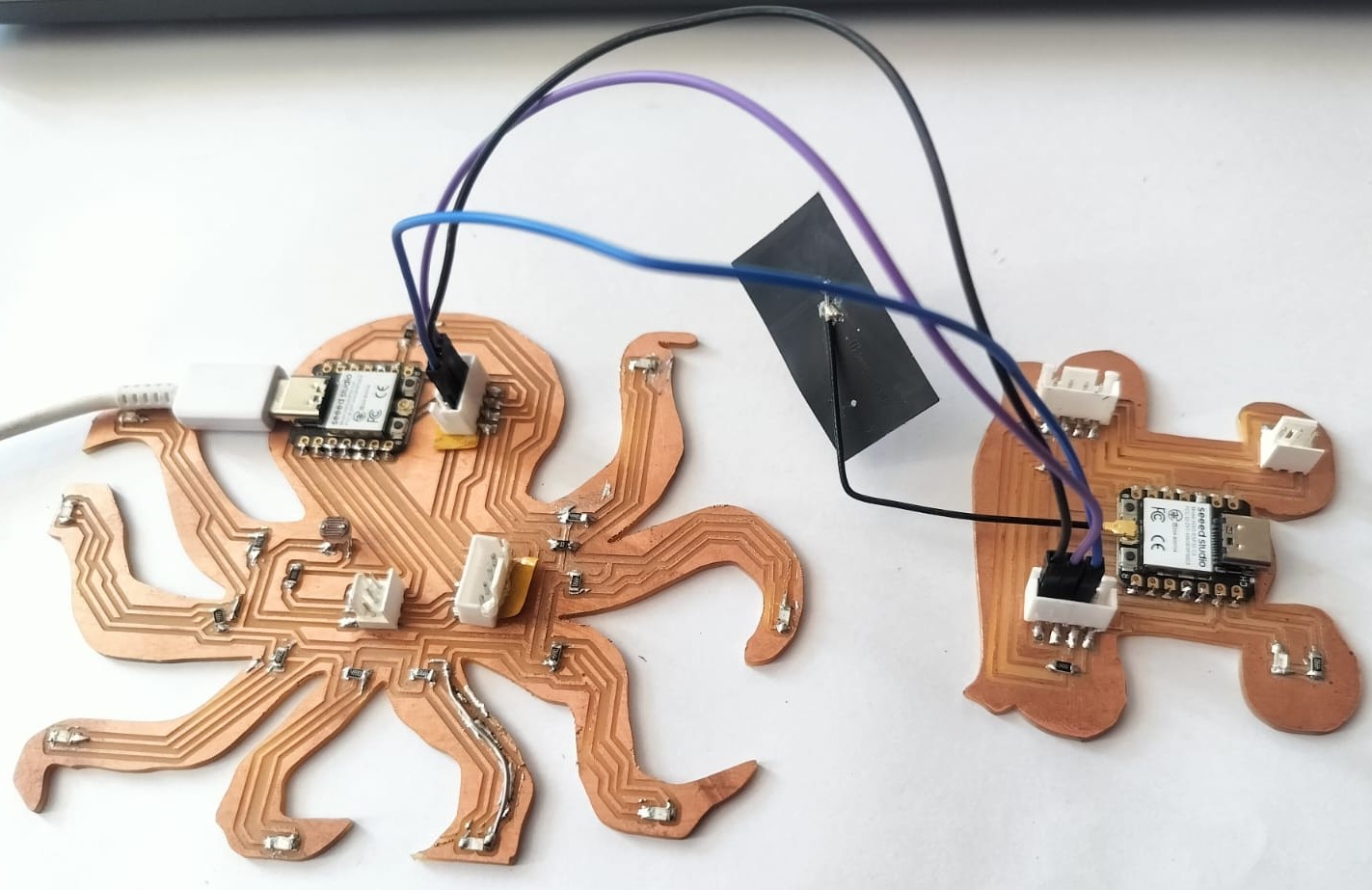
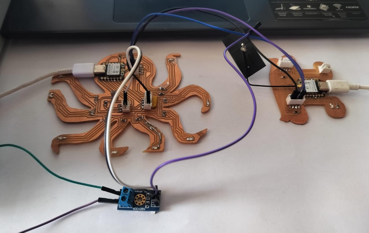
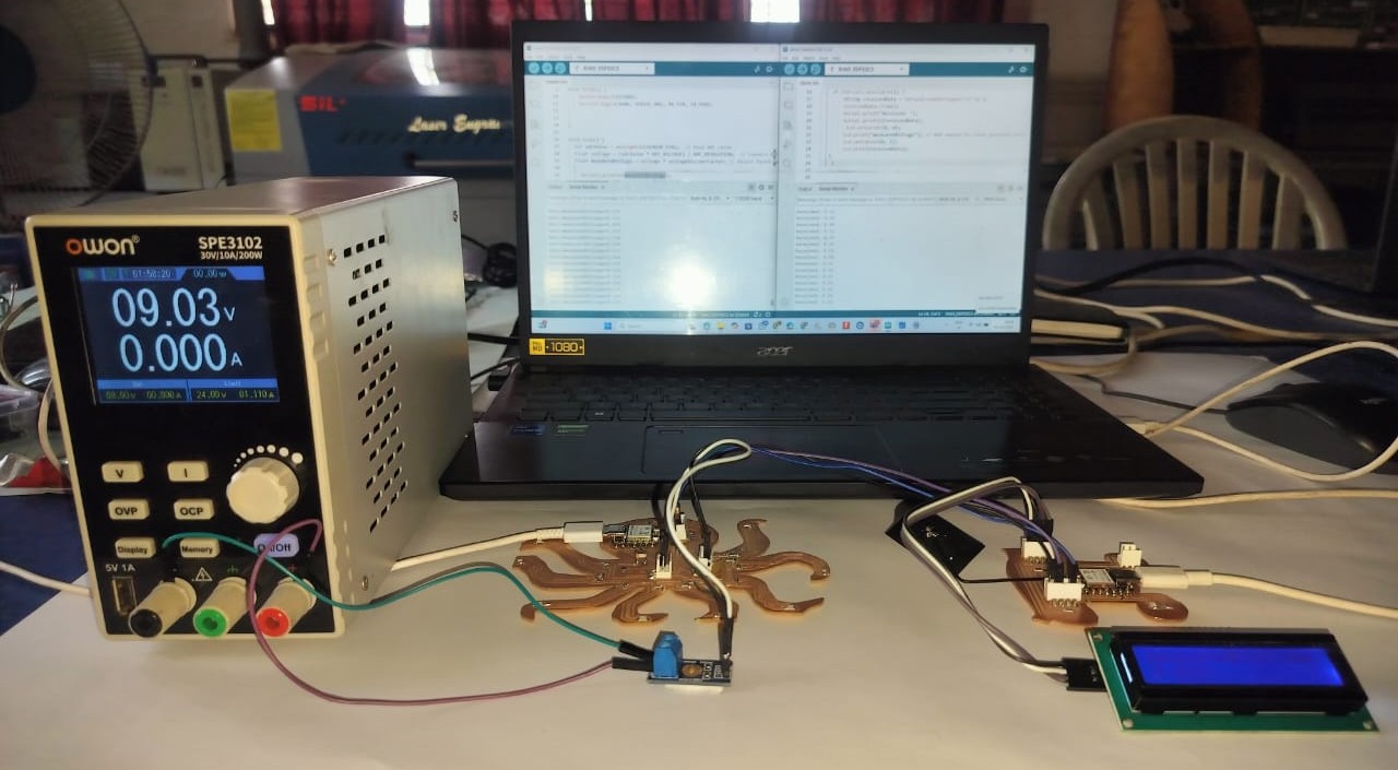
I used two ESP32 boards to establish serial communication. The boards were connected using jumper wires, where the TX (transmit) pin of the first board was linked to the RX (receive) pin of the second board, and vice versa. This configuration enabled proper data transmission between the two devices.
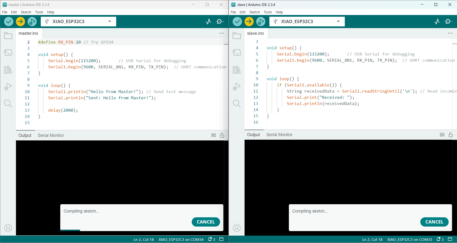
Once the circuit connections were complete, I launched the Arduino IDE, uploaded the code, selected the appropriate board and port settings, and verified the code to ensure it was free of errors before uploading it to the microcontroller.
The code upload process involves compiling the program, connecting the ESP32 board to the computer via a USB cable or programmer, and transferring the code using the Arduino IDE to enable execution on the device.
Data communication is handled using the I²C protocol through the Wire library, enabling efficient and reliable communication between the ESP32 microcontroller and connected peripheral devices.
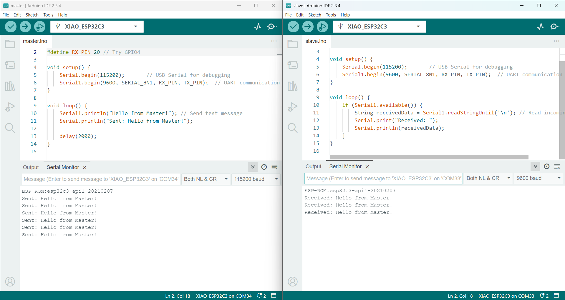
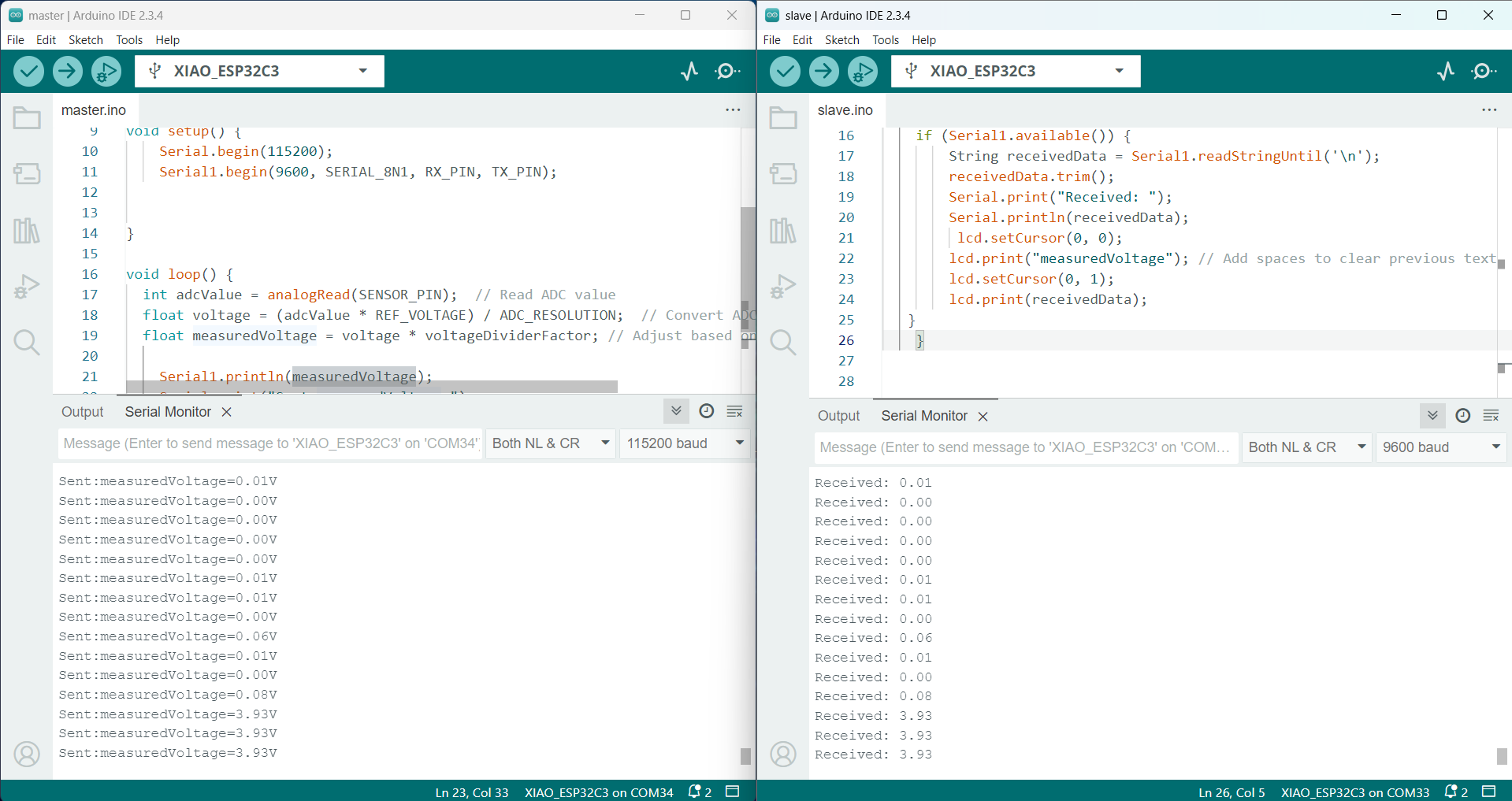
My test code is working successfully, and I have been able to transfer random data between the two boards. I can now integrate input and output devices into this setup and transmit data from Board A to Board B..
Voltage Sensor Testing
I began by testing the voltage sensor to understand how it functions with the code. The sensor was connected correctly, and power was supplied through an external power source. Once connected, I verified that the sensor was operating as expected.
I explored example codes online suitable for this voltage sensor. After configuring the pins according to my board setup, I successfully verified and uploaded the code to the microcontroller.
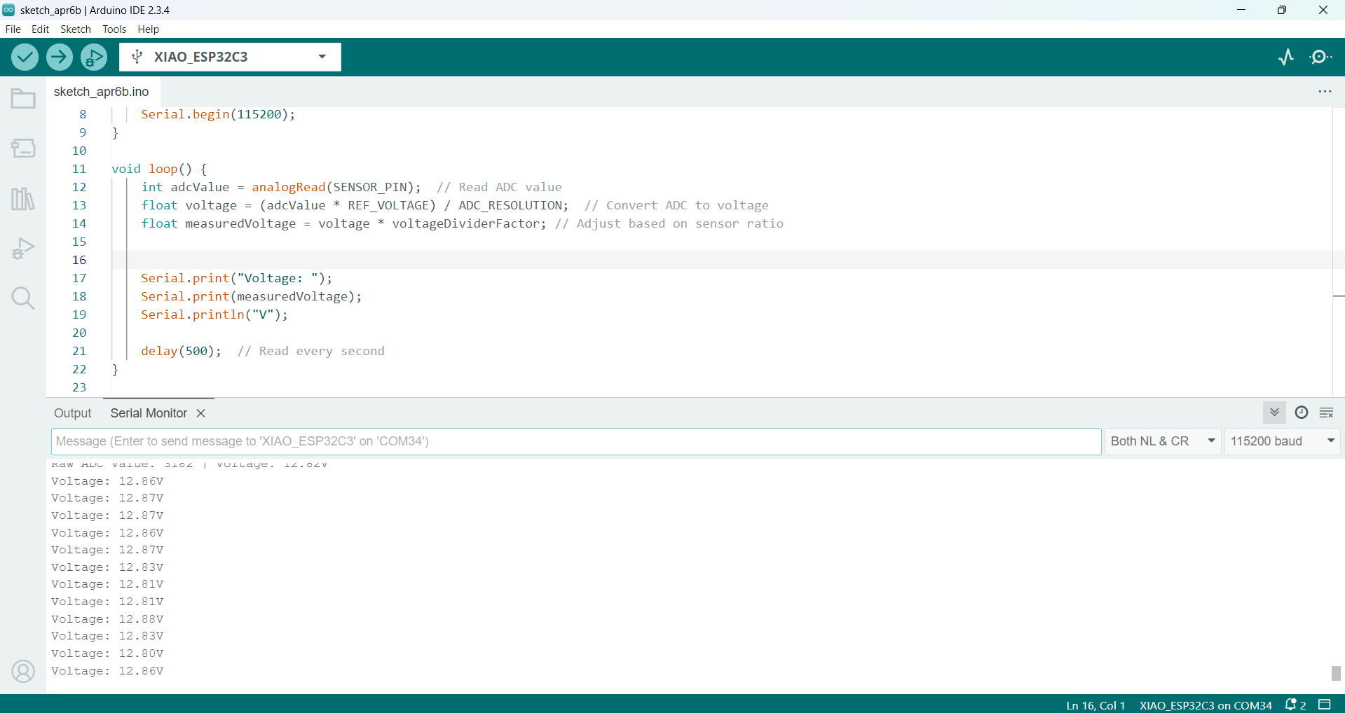
The voltage readings from the power supply started appearing on the Serial Monitor. However, the values were not accurate initially. To enhance accuracy, I adjusted the code and ensured proper sensor calibration. The revised setup allowed reliable data transmission using wired communication.
Wired Communication with Xio ESP32-C3 using Voltage Sensor and LED
For this assignment, I worked on wired communication using the Xio ESP32-C3 microcontroller. My goal was to send and receive signals between two boards through simple wired connections. I used a voltage sensor to read data on Board A and sent that data to Board B. The received voltage data was then displayed on an LCD,.
Components Used:
2x Xiao ESP32-C3 Boards
1x Voltage Sensor
1x LCD
Jumper Wires
Power Supply
Connection Table:
Component
Pin on Component
Pin on Xiao ESP32-C3
Description
UART Connection
TX (Board A)
RX (Board B - D7)
TX of Board A to RX of Board B
UART Connection
RX (Board A)
TX (Board B - D6)
RX of Board A to TX of Board B
Voltage Sensor
VCC
3.3V or 5V
Power supply to voltage sensor
Voltage Sensor
GND
GND
Common ground
Voltage Sensor
OUT
A2
Signal pin to analog input (A2)
LCD (I2C Device)
SDA
D4 (SDA)
I2C data line
LCD (I2C Device)
SCL
D5 (SCL)
I2C clock line
LCD (I2C Device)
VCC
3.3V
Power to I2C device
LCD (I2C Device)
GND
GND
Common ground
I connected two XIAO ESP32-C3 boards using UART communication. A voltage sensor is connected to analog pin A2, and an I2C LCD display is connected using the SDA and SCL pins, as shown in the connection table above.
Then, I opened the master and slave code and integrated the voltage sensor and LCD display code into it.
After uploading the updated code, the master began sending random data to the slave.
The voltage data was successfully sent to the slave's Serial Monitor and LCD, and the data transmission started as expected.
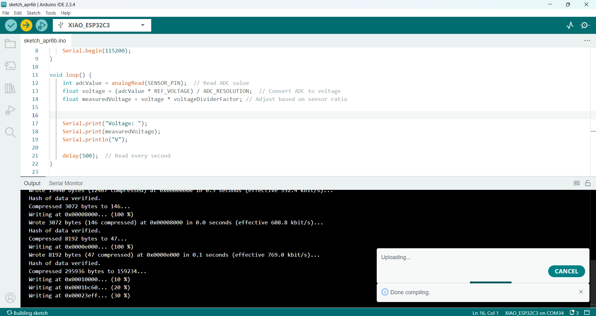
VoltageSensor Code
#define SENSOR_PIN 4   // Define the ADC pin (use a safe GPIO)
#define REF_VOLTAGE 3.3 // ESP32-C3 operates on 3.3V
#define ADC_RESOLUTION 4095 // 12-bit ADC resolution (0-4095)

float voltageDividerFactor = 4.3;  // Adjust based on the sensor calibration

void setup() {
    Serial.begin(115200);
}

void loop() {
    int adcValue = analogRead(SENSOR_PIN);  // Read ADC value
    float voltage = (adcValue * REF_VOLTAGE) / ADC_RESOLUTION;  // Convert ADC to voltage
    float measuredVoltage = voltage * voltageDividerFactor; // Adjust based on sensor ratio


    Serial.print("Voltage: ");
    Serial.print(measuredVoltage);
    Serial.println("V");

    delay(500);  // Read every second
}
Master Code
#define TX_PIN 21
#define RX_PIN 20
#define SENSOR_PIN 4   // Define the ADC pin (use a safe GPIO)
#define REF_VOLTAGE 3.3 // ESP32-C3 operates on 3.3V
#define ADC_RESOLUTION 4095 // 12-bit ADC resolution (0-4095)

float voltageDividerFactor = 4.3;  // Adjust based on the sensor calibration

void setup() {
    Serial.begin(115200);
    Serial1.begin(9600, SERIAL_8N1, RX_PIN, TX_PIN);


}

void loop() {
  int adcValue = analogRead(SENSOR_PIN);  // Read ADC value
  float voltage = (adcValue * REF_VOLTAGE) / ADC_RESOLUTION;  // Convert ADC to voltage
  float measuredVoltage = voltage * voltageDividerFactor; // Adjust based on sensor ratio

    Serial1.println(measuredVoltage);
    Serial.print("Sent:measuredVoltage=");
    Serial.print(measuredVoltage);
   Serial.println("V");
    delay(1000);
}
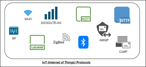
IoT communication refers to the exchange of data between smart devices that are connected to a local network or the internet. These devices send and receive data using different wired and wireless technologies such as Ethernet, Wi-Fi, Bluetooth, Zigbee, and LoRa.
IoT connectivity enables automation, remote monitoring, and control in various fields like industrial systems, smart homes, healthcare, and agriculture. It focuses on scalability, real-time data transfer, and low power usage. However, challenges like device compatibility, data security, and network congestion can arise.
Types of IoT Communication Models
Type
Medium/Technology
Key Features
Common Use Cases
Device-to-Device (D2D)
Bluetooth, Zigbee, Wi-Fi Direct
Direct local communication, low latency, energy-efficient
Smart lighting, motion-based automation
Device-to-Gateway
Wi-Fi Router, Mobile Phone, Smart Hub
Local filtering, protocol translation, enhanced security
Smart homes, industrial monitoring
Device-to-Cloud
Wi-Fi, Cellular (4G/5G), NB-IoT, LPWAN
Remote access, real-time data processing, high scalability
GPS tracking, remote health monitoring
Gateway-to-Cloud
Ethernet, Wi-Fi, Cellular
Aggregated data transmission, local decision-making
Smart agriculture, industrial IoT, smart cities
Back-End Communication
Cloud APIs, Analytics Platforms
Big data processing, visualization, ML integration
Alerts, insights, dashboards, system integration
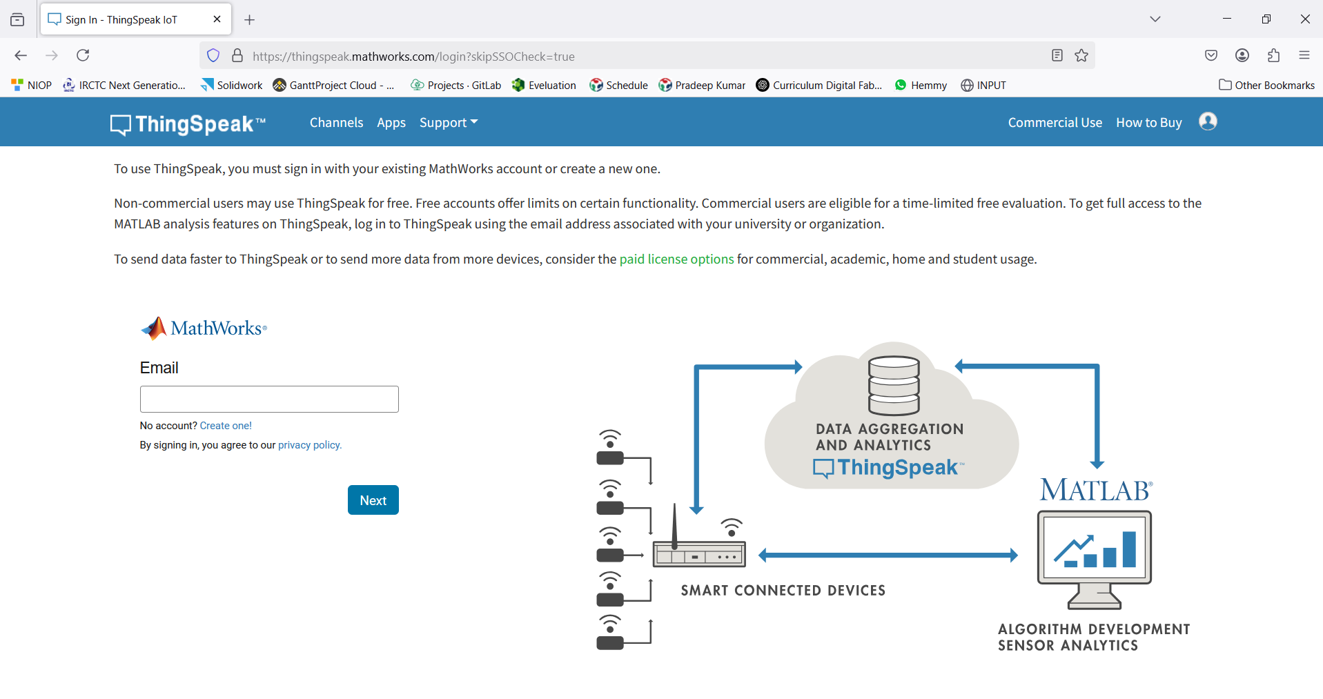
About ThingSpeak
ThingSpeak is a cloud-based IoT analytics platform that enables users to collect, visualize, and analyze live data online. It allows you to send data from IoT devices, such as the ESP32, to the cloud for real-time monitoring through interactive graphs and alerts.
For cloud-based communication in my project, I used the ThingSpeak platform.
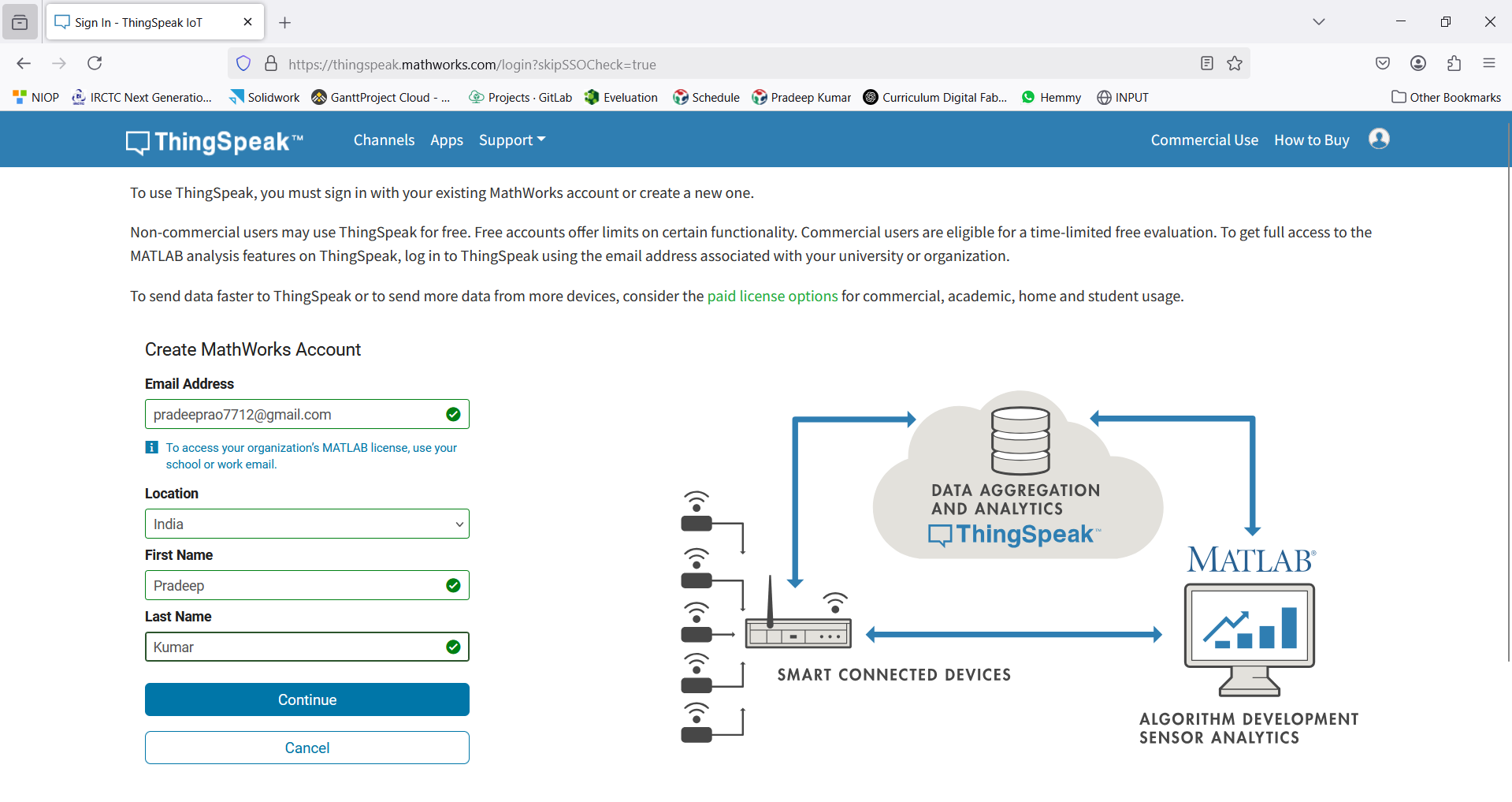
I started by creating an account on ThingSpeak. The process is illustrated in the steps below.
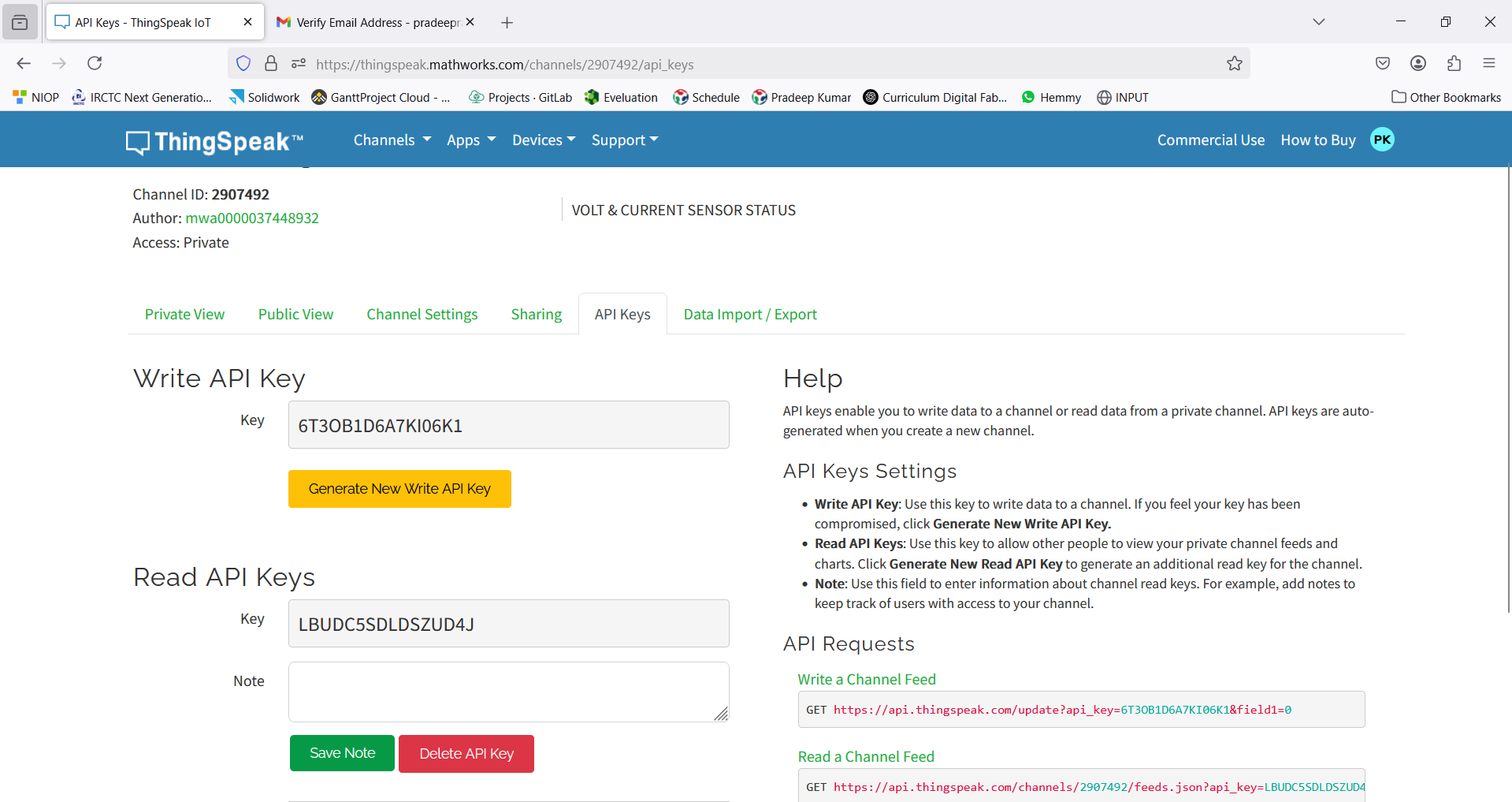
I also generated a Write API Key, which is essential for securely transmitting data from the microcontroller to the ThingSpeak server. This key uniquely identifies your channel and allows data uploads to it.
Visit the official ThingSpeak website.
Sign up by creating a new account, entering your details, and verifying your email address via the link sent to you.
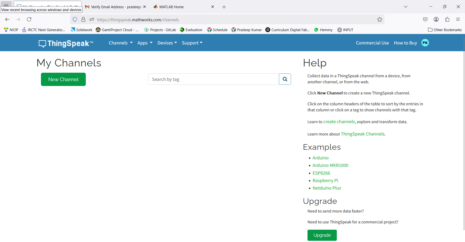
Click on “Add Channel” to create a new data channel.
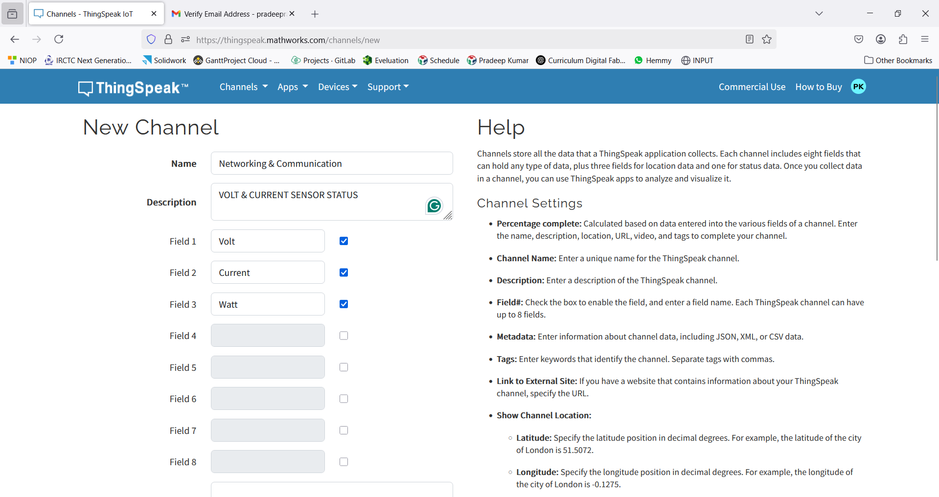
Enter the Name, Description, and required Fields for your channel.
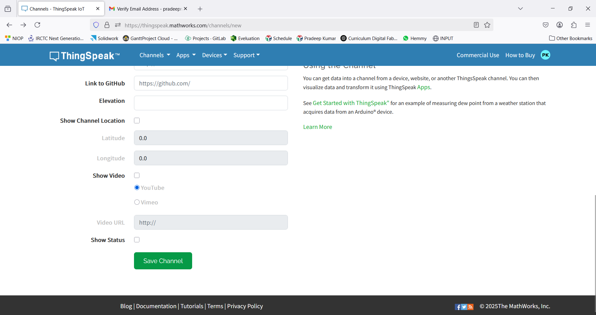
Click “Save Channel” to store your settings.
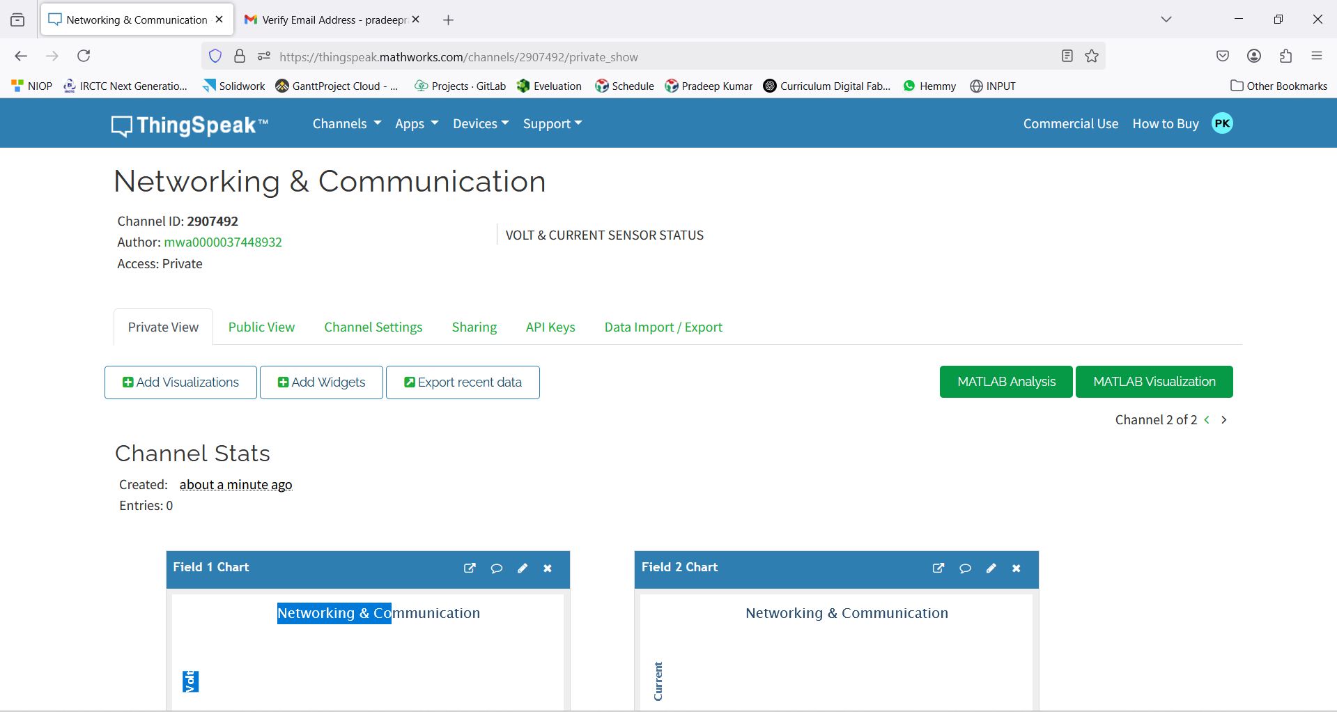
Navigate to the “Private View” tab to access your channel dashboard.
Go to the “API Keys” section and copy your Write API Key. This key will be used in your IoT code to upload data to ThingSpeak.
Testing-IOT_Code
#include WiFi.h
#include HTTPClient.h
// Replace with your WiFi credentials
const char* ssid = "FABLAB";
const char* password = "12345678";
// Replace with your ThingSpeak Write API Key
const char* apiKey = "15DBNHTNHL25YMYN";
// ThingSpeak API URL
const char* server = "http://api.thingspeak.com/update";
void setup() {
Serial.begin(115200);
WiFi.begin(ssid, password);
Serial.print("Connecting to WiFi...");
while (WiFi.status() != WL_CONNECTED) {
Serial.print(".");
delay(1000);
}
Serial.println("\nConnected to WiFi!");
}
void loop() {
if (WiFi.status() == WL_CONNECTED) {
HTTPClient http;
// Generate random values
int value1 = random(20, 40); // Example: Temperature
int value2 = random(30, 60); // Example: Humidity
int value3 = random(100, 500); // Example: Light Intensity
// Construct the request URL
String url = String(server) + "?api_key=" + apiKey +
"&field1=" + String(value1) +
"&field2=" + String(value2) +
"&field3=" + String(value3);
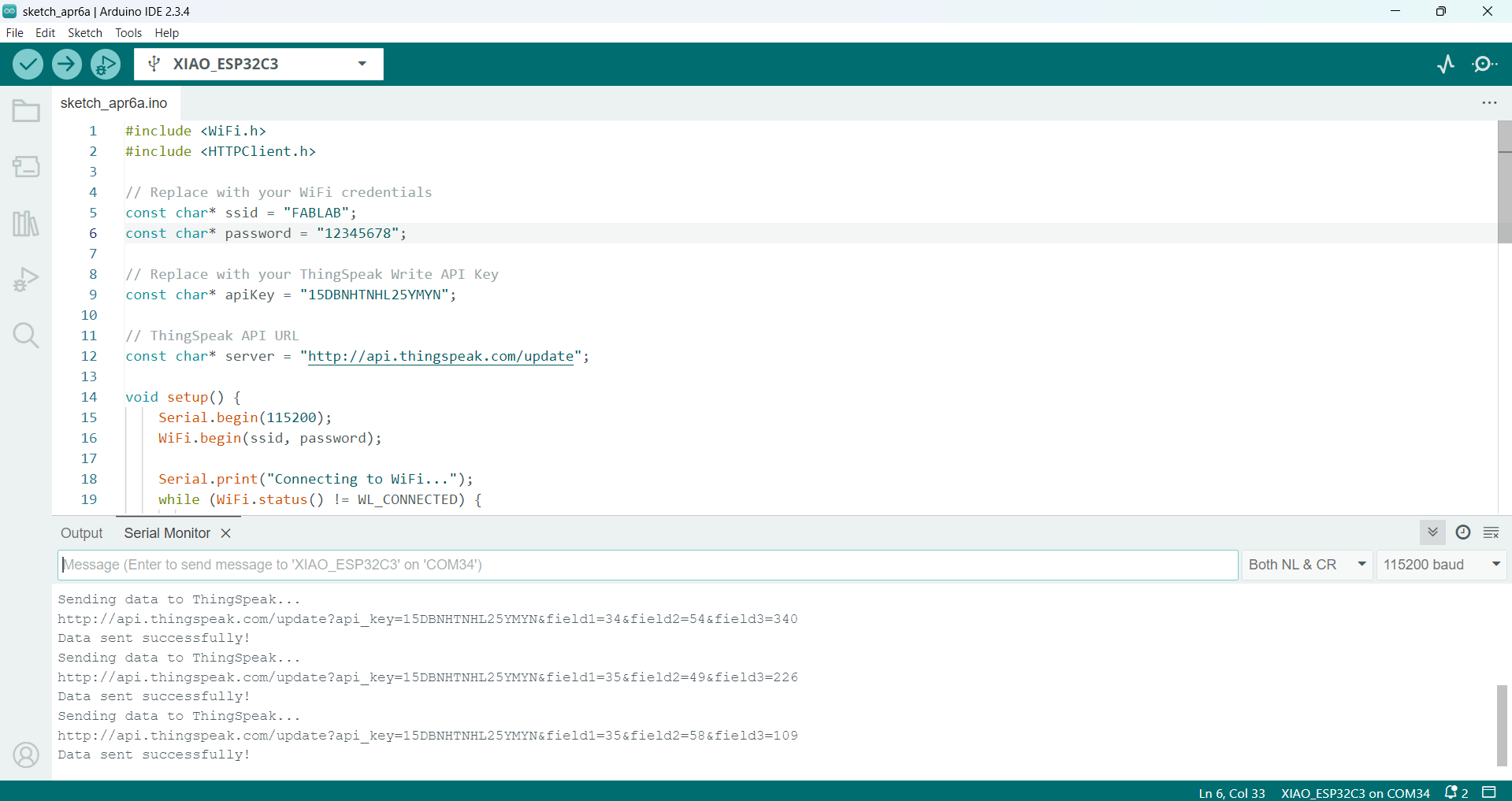
Serial.println("Sending data to ThingSpeak...");
Serial.println(url);
// Send data to ThingSpeak
http.begin(url);
int httpCode = http.GET();
if (httpCode > 0) {
Serial.println("Data sent successfully!");
} else {
Serial.println("Failed to send data.");
}
http.end();
} else {
Serial.println("WiFi Disconnected!");
}
delay(15000); // ThingSpeak allows updates every 15 seconds
}
I am now fully prepared to send data to the cloud, marking a significant step in my project.
The code was successfully verified in the Arduino IDE, ensuring that all functions are working as intended.
Uploaded the code to the ESP32-C3 board.
Before uploading the code, I entered the API Key, SSID, and password, which are essential for connecting the device to the network.
The board has successfully connected to both the internet and the cloud server, allowing seamless data transmission.
IoT Communication using Voltage Sensor + Current Sensor and OLED with Xiao ESP32-C3
"For my IoT communication project, I plan to combine both the voltage and current sensors to create a formula that will calculate the power. This will help me determine the power rating of both the system and the OLED, as well as measure how much power is being generated. I also want to display this data on my IoT cloud platform, where I can visualize it through graphs."
Components Used:
Voltage Sensor
Current Sensor
Power Supply
Xiao ESP32-C3 Board
OLED Display
Connection
S.No
Component
Pin on Component (Board A)
Pin on Xiao ESP32-C3 (Board A)
Description
1
Voltage Sensor
VCC
3.3V or 5V
Power supply for voltage sensor
2
Voltage Sensor
GND
GND
Common ground for Board A
3
Voltage Sensor
OUT
A2
Signal pin from voltage sensor to A2
4
Current Sensor
VCC
3.3V or 5V
Power supply for current sensor
5
Current Sensor
GND
GND
Common ground for Board A
6
Current Sensor
OUT
A0
Signal pin from current sensor to A0
7
Power Supply
-
+ (Power) and - (Ground)
Power supply for both sensors
S.No
Component
Pin on Component (Board B)
Pin on Xiao ESP32-C3 (Board B)
Description
1
OLED Display (I2C)
SDA
D4
I2C data line for OLED
2
OLED Display (I2C)
SCL
D5
I2C clock line for OLED
3
OLED Display (I2C)
VCC
3.3V
Power supply for OLED
4
OLED Display (I2C)
GND
GND
Common ground for Board B
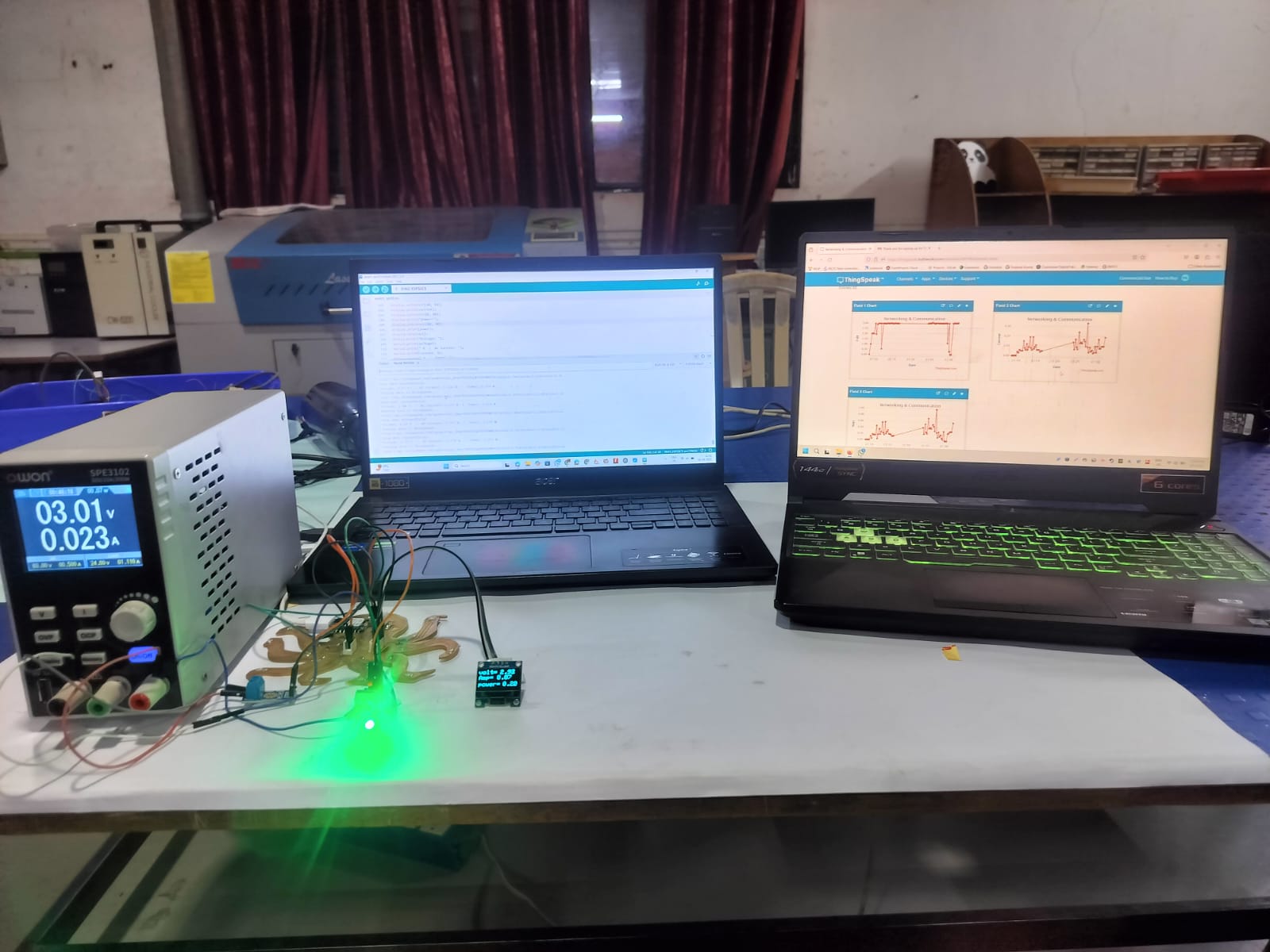
I created this code to monitor power generation by connecting both current and voltage sensors. This allowed me to display voltage, current, and power values on my dashboard to track energy consumption. Similarly, I used another code in which I included my Wi-Fi SSID, password, and API key to enable wireless data transmission to the cloud. With this setup, I can also view the main voltage, current, and power directly on the OLED display connected to the device
"According to the table, I have properly fixed the connections for both my boards. To run the project, I included the API key generated by ThingSpeak in my code."
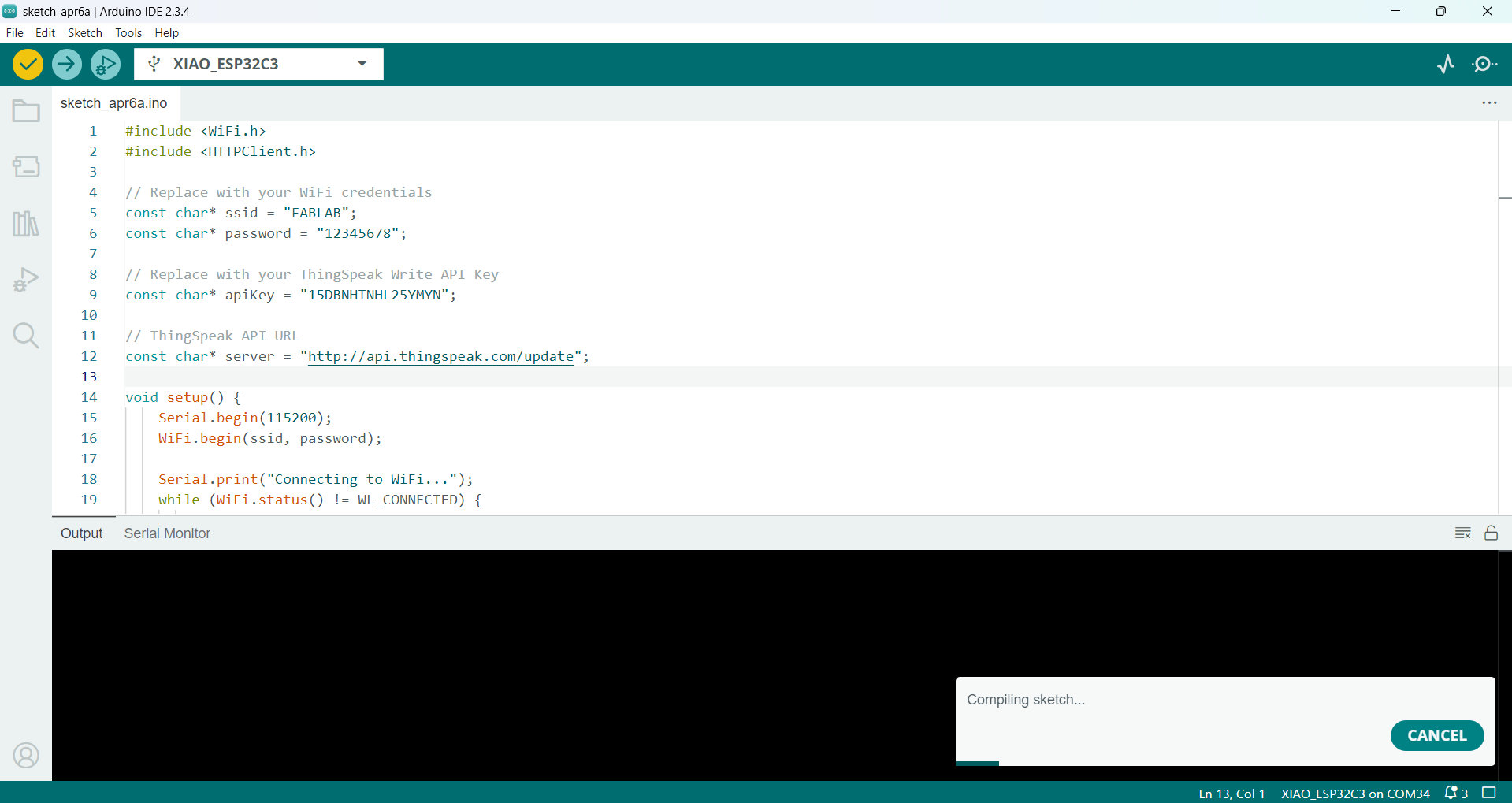
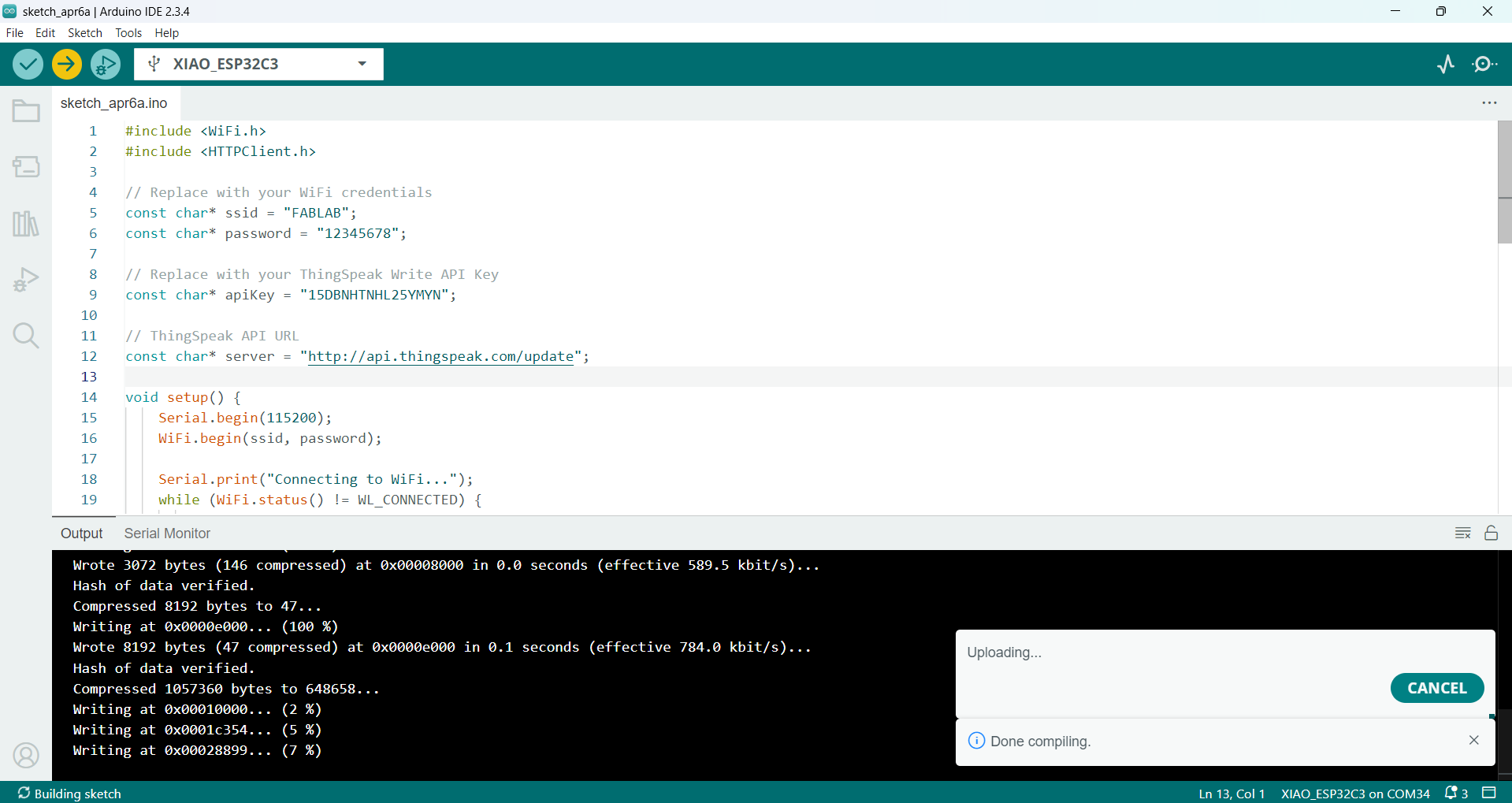
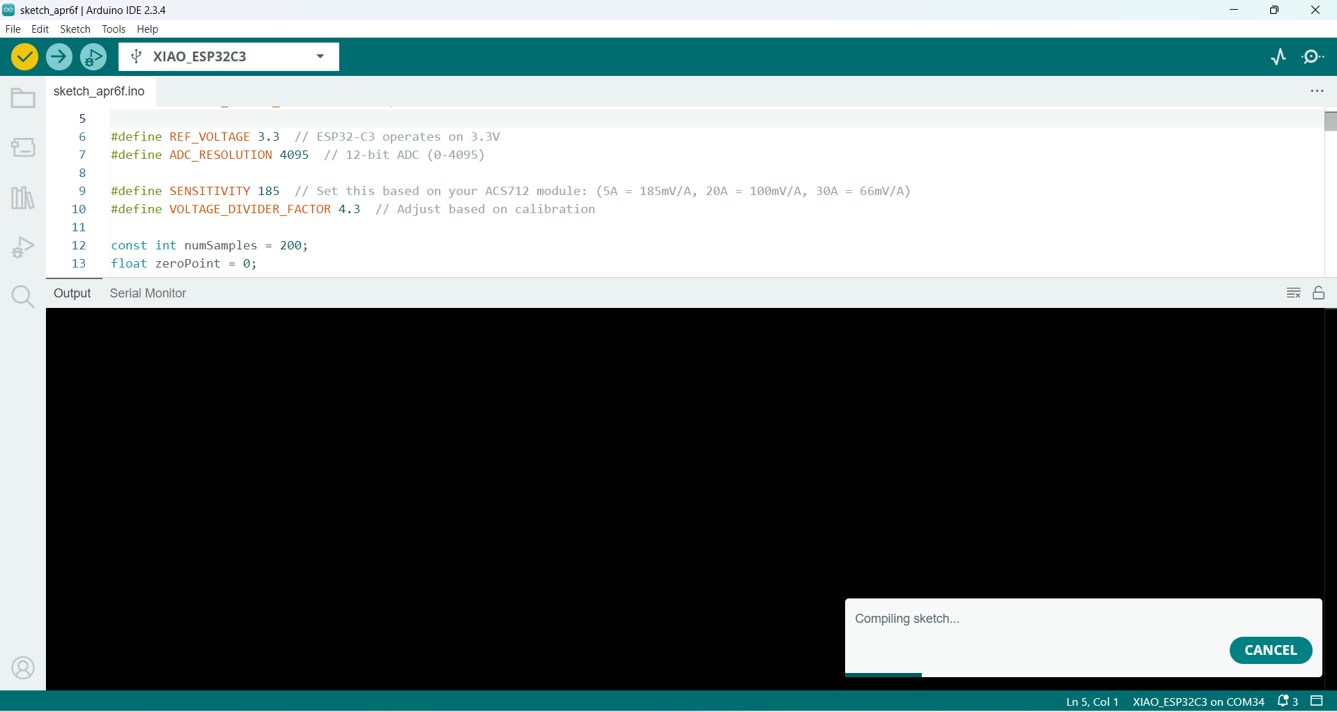
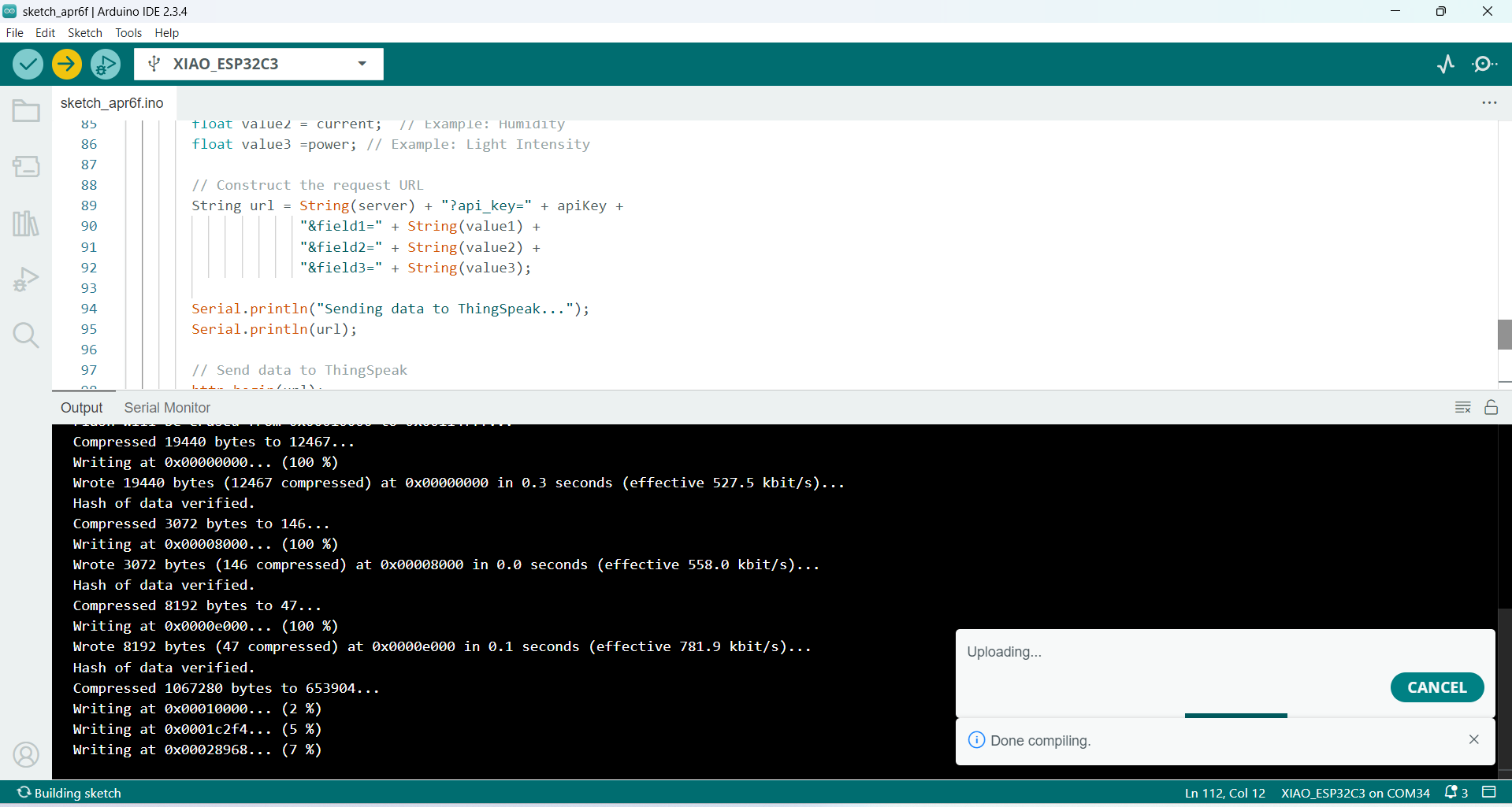
Code Verification and Upload:
Figure 1: Code successfully verified and uploaded to the board
After writing and verifying the code, I uploaded it to the ESP32-C3 board. The compilation was successful, and the code was uploaded without any errors.
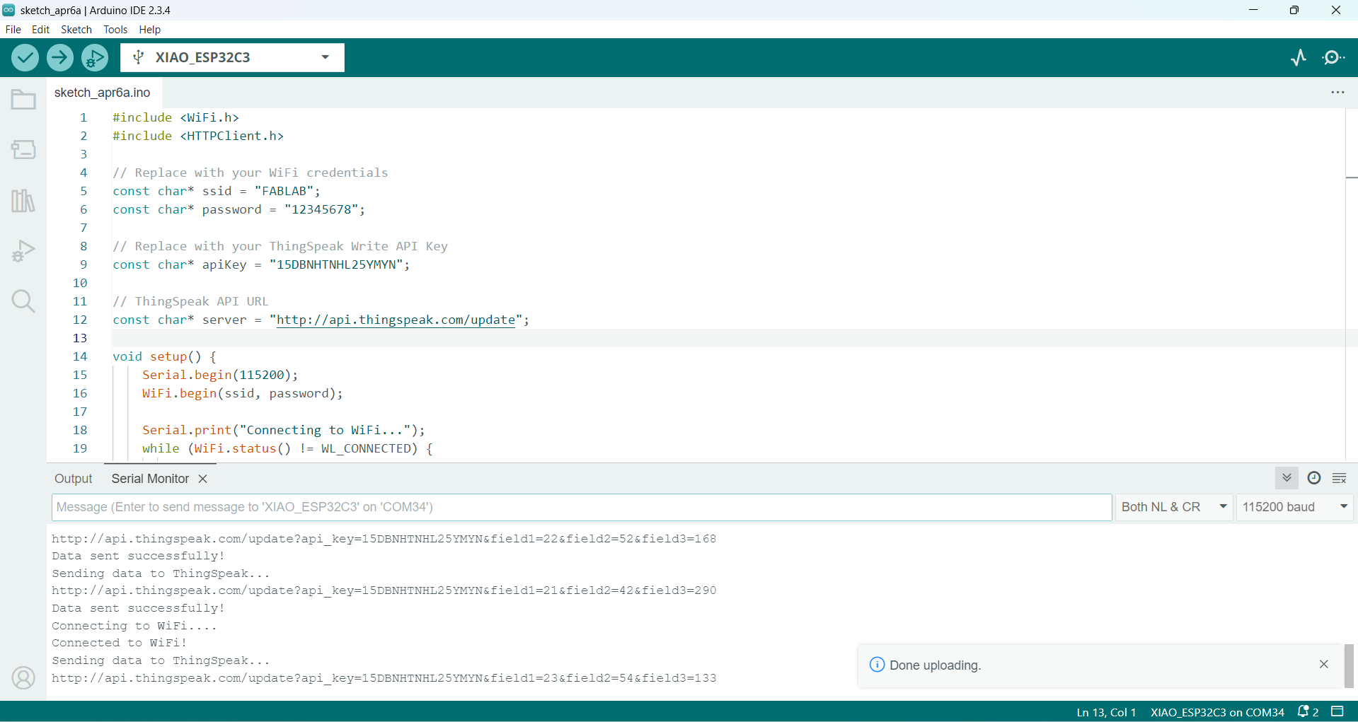
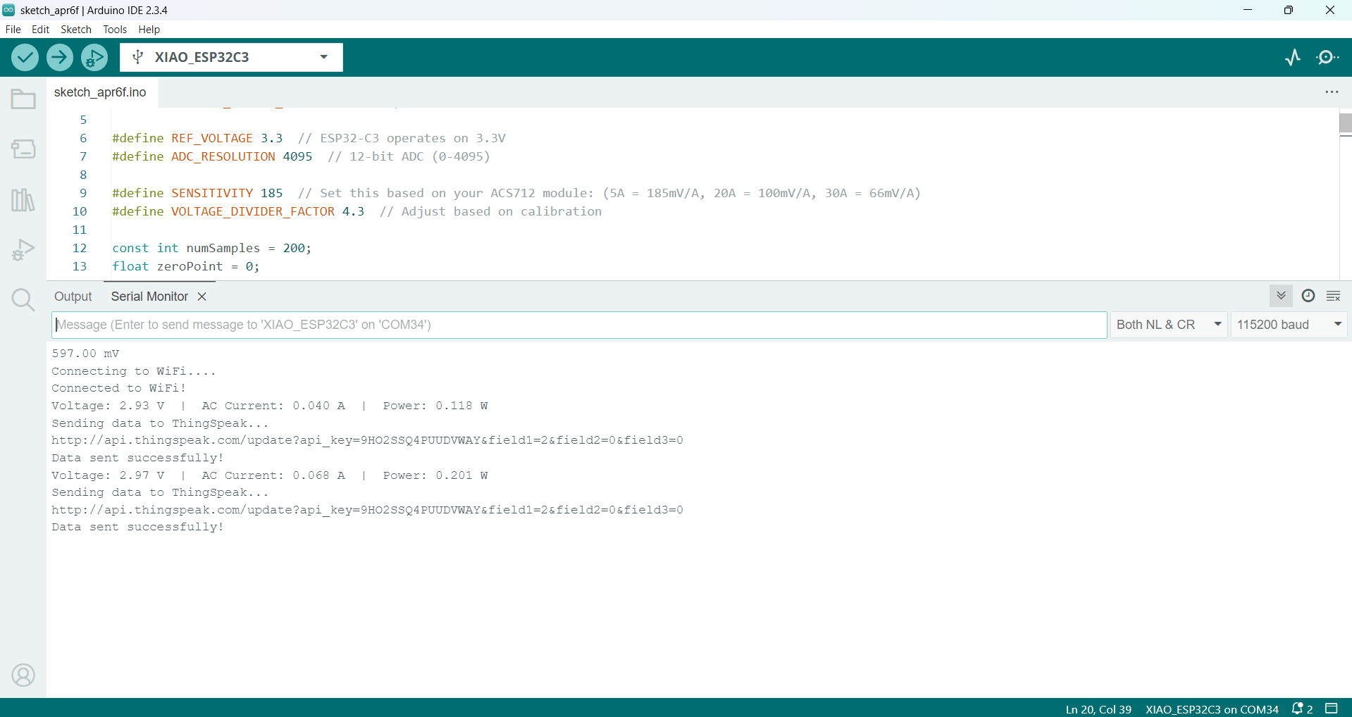
Wi-Fi Connection Established:
Figure 2: Device connecting to Wi-Fi as shown in the Serial Monitor
The Serial Monitor showed that the device was successfully connecting to my Wi-Fi network using the SSID and password provided in the code.
Cloud Connection:
Figure 3: Device successfully connected to the cloud platform
Along with the Wi-Fi connection, the device also connected to the cloud platform using the API key, confirming that the cloud communication setup was working properly.
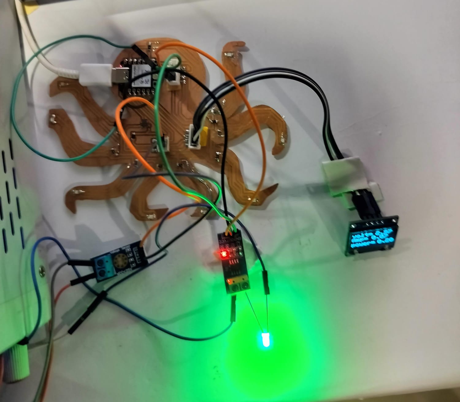
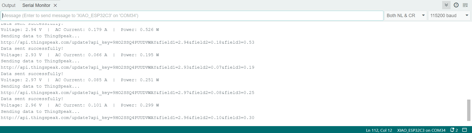
Data Transmission Success:
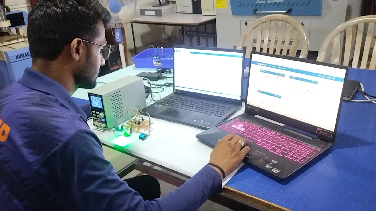
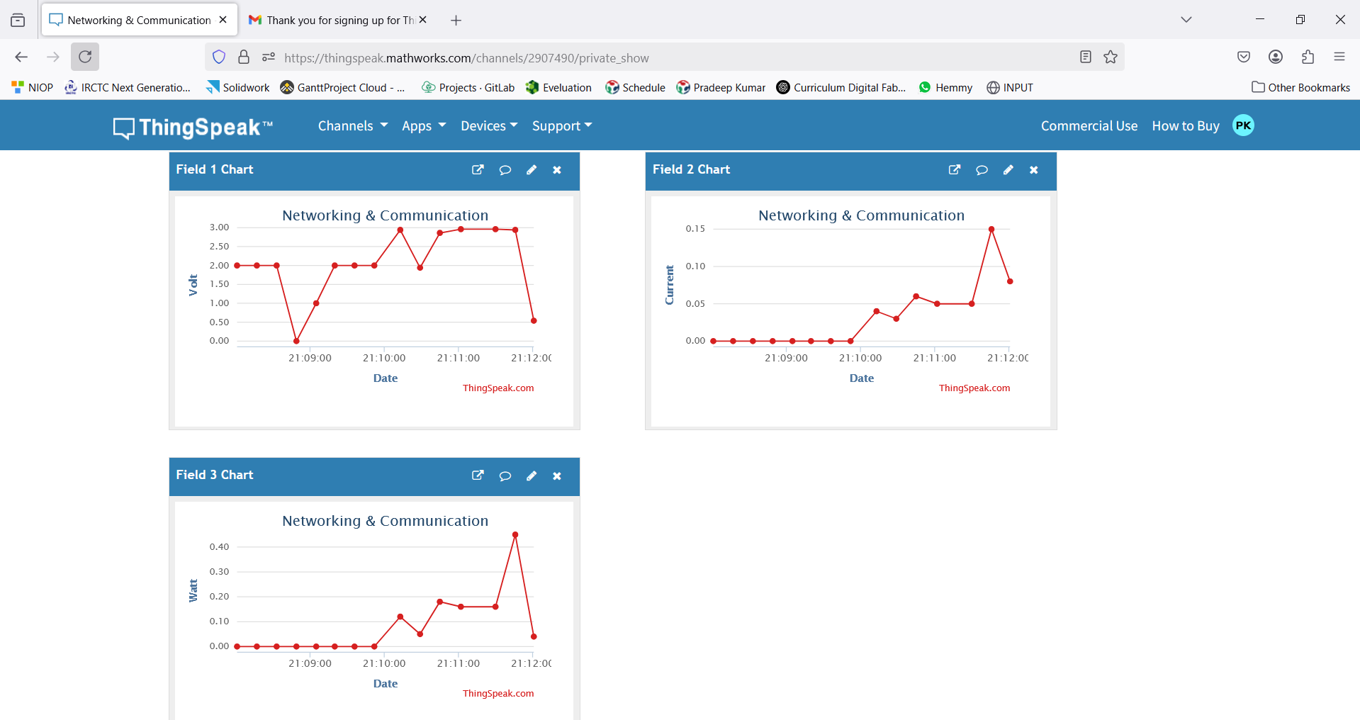
Figure 4: Real-time data monitoring and successful communication
The code was successfully transmitting data such as voltage, current, and power values, which were visible both on the OLED display and on the cloud dashboard.
Data is also going in the cloud dashboard.
Data is also going in the cloud dashboard.
ThingSpeak – Cloud Communication
IOT_Code
#include WiFi.h
#include HTTPClient.h
#include Wire.h
#include Adafruit_GFX.h
#include Adafruit_SSD1306.h

// OLED display width and height
#define SCREEN_WIDTH 128
#define SCREEN_HEIGHT 64

// Create display object
Adafruit_SSD1306 display(SCREEN_WIDTH, SCREEN_HEIGHT, &Wire, -1);
#define VOLTAGE_SENSOR_PIN A2   // ADC pin for voltage sensor
#define CURRENT_SENSOR_PIN A0  // ADC pin for ACS712 current sensor

#define REF_VOLTAGE 3.3  // ESP32-C3 operates on 3.3V
#define ADC_RESOLUTION 4095  // 12-bit ADC (0-4095)

#define SENSITIVITY 185  // Set this based on your ACS712 module: (5A = 185mV/A, 20A = 100mV/A, 30A = 66mV/A)
#define VOLTAGE_DIVIDER_FACTOR 4.3  // Adjust based on calibration

const int numSamples = 200;
float zeroPoint = 0;

// Replace with your WiFi credentials
const char* ssid = "FABLAB";
const char* password = "12345678";

// Replace with your ThingSpeak Write API Key
const char* apiKey = "9HO2SSQ4PUUDVWAY";

// ThingSpeak API URL
const char* server = "http://api.thingspeak.com/update";

void setup() {
Serial.begin(115200);
if (!display.begin(SSD1306_SWITCHCAPVCC, 0x3C)) { // 0x3C is the I2C address
Serial.println(F("SSD1306 allocation failed"));
while (1); // Halt execution
}

display.clearDisplay();
display.setTextSize(2);
display.setTextColor(SSD1306_WHITE);
pinMode(VOLTAGE_SENSOR_PIN, INPUT);
pinMode(CURRENT_SENSOR_PIN, INPUT);
delay(500);

// Calibrate Zero Point (Idle Voltage when NO Load)
long sum = 0;
for (int i = 0; i < numSamples; i++) {
sum += analogReadMilliVolts(CURRENT_SENSOR_PIN);
delay(5);
}
zeroPoint = sum / numSamples;
Serial.print("Zero Point (No Load): ");
Serial.print(zeroPoint);
Serial.println(" mV");


WiFi.begin(ssid, password);

Serial.print("Connecting to WiFi...");
while (WiFi.status() != WL_CONNECTED) {
Serial.print(".");
delay(100);
}
Serial.println("\nConnected to WiFi!");
}
// Function to measure AC Current RMS correctly
float readACCurrent() {
float sumSquared = 0;
for (int i = 0; i < numSamples; i++) {
float voltage = analogReadMilliVolts(CURRENT_SENSOR_PIN);
float current = (voltage - zeroPoint) / SENSITIVITY;
sumSquared += current * current;
delayMicroseconds(50);  // Sampling rate improvement
}
return sqrt(sumSquared / numSamples);  // RMS Current Calculation
}

// Function to measure Voltage
float readVoltage() {
int adcValue = analogRead(VOLTAGE_SENSOR_PIN);
float voltage = (adcValue * REF_VOLTAGE) / ADC_RESOLUTION;
return voltage * VOLTAGE_DIVIDER_FACTOR;  // Adjust with divider factor
}
void loop() {
if (WiFi.status() == WL_CONNECTED) {
HTTPClient http;
float voltage = readVoltage();
float current = readACCurrent();
float power = voltage * current;  // Power Calculation: P = V * I
display.clearDisplay();
display.setCursor(0, 0);
display.print("volt=");
display.setCursor(70, 0);
display.print(voltage);
display.setCursor(0, 18);
display.print("Amp=");
display.setCursor(60, 18);
display.print(current);
display.setCursor(0, 40);
display.print("power=");
display.setCursor(80, 40);
display.print(power);
display.display();
Serial.print("Voltage: ");
Serial.print(voltage);
Serial.print(" V  |  AC Current: ");
Serial.print(current, 3);
Serial.print(" A  |  Power: ");
Serial.print(power, 3);
Serial.println(" W");
// Generate random values
float value1 = voltage;  // Example: Temperature
float value2 = current;  // Example: Humidity
float value3 =power; // Example: Light Intensity

// Construct the request URL
String url = String(server) + "?api_key=" + apiKey +
            "&field1=" + String(value1) +
            "&field2=" + String(value2) +
            "&field3=" + String(value3);

Serial.println("Sending data to ThingSpeak...");
Serial.println(url);

// Send data to ThingSpeak
http.begin(url);
int httpCode = http.GET();

if (httpCode > 0) {
  Serial.println("Data sent successfully!");
} else {
  Serial.println("Failed to send data.");
}

http.end();
} else {
Serial.println("WiFi Disconnected!");
}

delay(500); // ThingSpeak allows updates every 15 seconds
}
I worked with all three types of communication, and I really enjoyed it. I was able to send the data successfully. I got help from a person named Ramesh, who supported me with the coding. Because of his help, there were very few errors. I also learned a lot from him.
Now, I have completed 50% of the coding for my final project.