In the Embedded Networking and Communications group assignment, we successfully demonstrated a wireless connection between two XIAO ESP32-C3 boards using ESP-NOW. The transmitter and receiver codes were configured, the MAC addresses were obtained, and communication between the current sensors was verified. The system's functionality was confirmed when the data was transmitted and displayed on an OLED panel. This project provided valuable hands-on experience in wireless communication, sensor integration, and real-time data visualization, which will be beneficial for future IoT applications.
Group assignment
Embedded Networking and Communications
Task: Embedded Networking and Communications
Group assignment:
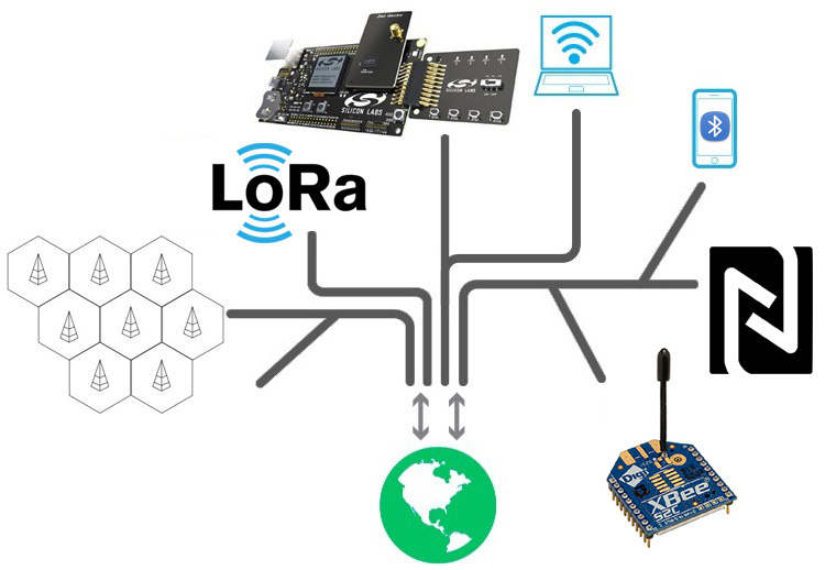
Devices can exchange data without physical wires by using radio waves. This allows for greater mobility, flexibility, and easier installation. Common wireless technologies include Wi-Fi, Bluetooth, Zigbee, and LoRa. Each technology has its own use based on data speed, battery usage, and range. While wireless systems are convenient, they may face challenges like security risks, limited range, and signal interference.
| Technology | Range | Frequency | Main Use | Example |
|---|---|---|---|---|
| Wi-Fi | Up to 100 meters | 2.4 GHz / 5 GHz | Internet access, local networking | Home/office wireless routers |
| Bluetooth | Up to 10 meters | 2.4 GHz | Short-range device connectivity | Wireless earphones, smartwatches |
| Zigbee | 10–100 meters | 2.4 GHz | Home automation, smart meters | Smart lighting, security systems |
| LoRa | Up to 15 kilometers | 433 MHz / 868 MHz | Long-range IoT communication | Smart agriculture, smart cities |
| NFC | Up to 4 cm | 13.56 MHz | Contactless payments, identity verification | Google Pay, metro cards |
| Infrared (IR) | Few meters (line-of-sight) | 850–950 nm (IR spectrum) | Short-range control signals | TV remotes, AC remotes |
| Cellular (3G/4G/5G) | Nationwide (via cell towers) | Varies (700 MHz to 2.6 GHz+) | Mobile data, voice calls, IoT | Smartphones, mobile broadband |
| Satellite Communication | Global (via orbiting satellites) | Varies (GHz range) | Remote connectivity, broadcasting | GPS, satellite TV, weather reports |
To begin communication between two XIAO ESP32-C3 boards, the initial step was to retrieve the MAC address of the receiver device. This process involved locating the MAC address of the receiver to establish a connection and enable communication between the two devices.
We compiled the code for the MAC address, verified it, and then uploaded it successfully
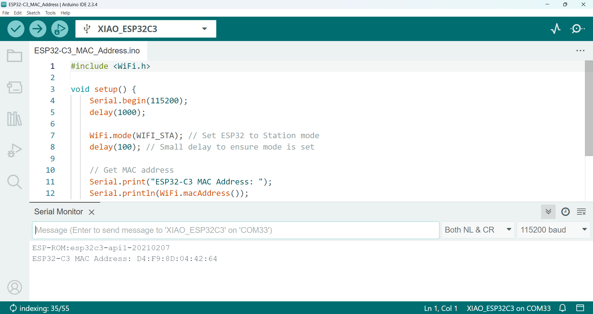
We researched online for an appropriate code to detect the MAC address. After successfully implementing and testing the code, I was able to retrieve the MAC address of the board."
#include WiFi.h

void setup() {
    Serial.begin(115200);
    delay(1000);

    WiFi.mode(WIFI_STA); // Set ESP32 to Station mode
    delay(100); // Small delay to ensure mode is set

    // Get MAC address
    Serial.print("ESP32-C3 MAC Address: ");
    Serial.println(WiFi.macAddress());
}

void loop() {
    // Do nothing
}
After obtaining the MAC address, I researched transmitter and receiver codes online. By using these codes, I was able to establish data communication between Board A and Board B.
The transmitter code is responsible solely for transmitting data. It can send various types of data, whether it's random information or sensor data, to a specific device. The main function of the transmitter code is to send this data. Once I include my MAC address in the code, it enables connection with other devices that also contain the same MAC address. Upon establishing the connection, the transmitter begins to send the data.
#include WiFi.h
#include esp_now.h


uint8_t receiverMAC[] = {0xD4, 0xF9, 0x8D, 0x04, 0x42, 0x64}; // Change to actual receiver MAC

// Data structure to send
typedef struct struct_message {
    int value;
} struct_message;

struct_message myData;

// Callback when data is sent
void onDataSent(const uint8_t *mac_addr, esp_now_send_status_t status) {
    Serial.print("Send Status: ");
    Serial.println(status == ESP_NOW_SEND_SUCCESS ? "Success" : "Fail");
}

void setup() {
    Serial.begin(115200);
    WiFi.mode(WIFI_STA); // Set ESP32 to Station mode

    // Initialize ESP-NOW
    if (esp_now_init() != ESP_OK) {
        Serial.println("ESP-NOW Init Failed!");
        return;
    }

    esp_now_register_send_cb(onDataSent);

    // Register peer
    esp_now_peer_info_t peerInfo = {};
    memcpy(peerInfo.peer_addr, receiverMAC, 6);
    peerInfo.channel = 0;
    peerInfo.encrypt = false;

    if (esp_now_add_peer(&peerInfo) != ESP_OK) {
        Serial.println("Failed to add peer");
        return;
    }
}

void loop() {
    myData.value = random(1, 100);;

    // Send data
    esp_err_t result = esp_now_send(receiverMAC, (uint8_t *)&myData, sizeof(myData));

    if (result == ESP_OK) {
        Serial.println("Sent successfully");
    } else {
        Serial.println("Error sending data");
    }

    delay(2000); // Send every 2 seconds
}
The function of the receiver code is to receive data and display it either on the serial monitor or any output device we are using.
#include WiFi.h
#include esp_now.h


uint8_t receiverMAC[] = {0xD4, 0xF9, 0x8D, 0x04, 0x42, 0x64}; // Change to actual receiver MAC

// Data structure to send
typedef struct struct_message {
    int value;
} struct_message;

struct_message myData;

// Callback when data is sent
void onDataSent(const uint8_t *mac_addr, esp_now_send_status_t status) {
    Serial.print("Send Status: ");
    Serial.println(status == ESP_NOW_SEND_SUCCESS ? "Success" : "Fail");
}

void setup() {
    Serial.begin(115200);
    WiFi.mode(WIFI_STA); // Set ESP32 to Station mode

    // Initialize ESP-NOW
    if (esp_now_init() != ESP_OK) {
        Serial.println("ESP-NOW Init Failed!");
        return;
    }

    esp_now_register_send_cb(onDataSent);

    // Register peer
    esp_now_peer_info_t peerInfo = {};
    memcpy(peerInfo.peer_addr, receiverMAC, 6);
    peerInfo.channel = 0;
    peerInfo.encrypt = false;

    if (esp_now_add_peer(&peerInfo) != ESP_OK) {
        Serial.println("Failed to add peer");
        return;
    }
}

void loop() {
    myData.value = random(1, 100);;

    // Send data
    esp_err_t result = esp_now_send(receiverMAC, (uint8_t *)&myData, sizeof(myData));

    if (result == ESP_OK) {
        Serial.println("Sent successfully");
    } else {
        Serial.println("Error sending data");
    }

    delay(2000); // Send every 2 seconds
}
In both codes, I included my own MAC address like this: uint8_t receiverMAC[] = {0xD4, 0xF9, 0x8D, 0x04, 0x42, 0x64}; // Replace with the actual receiver MAC address.
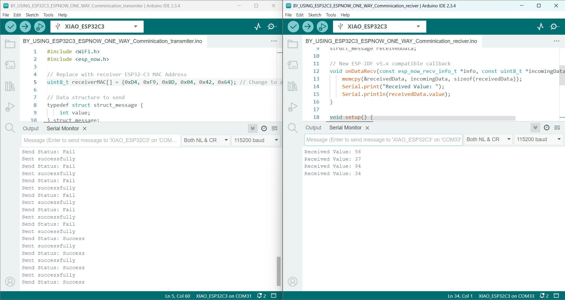
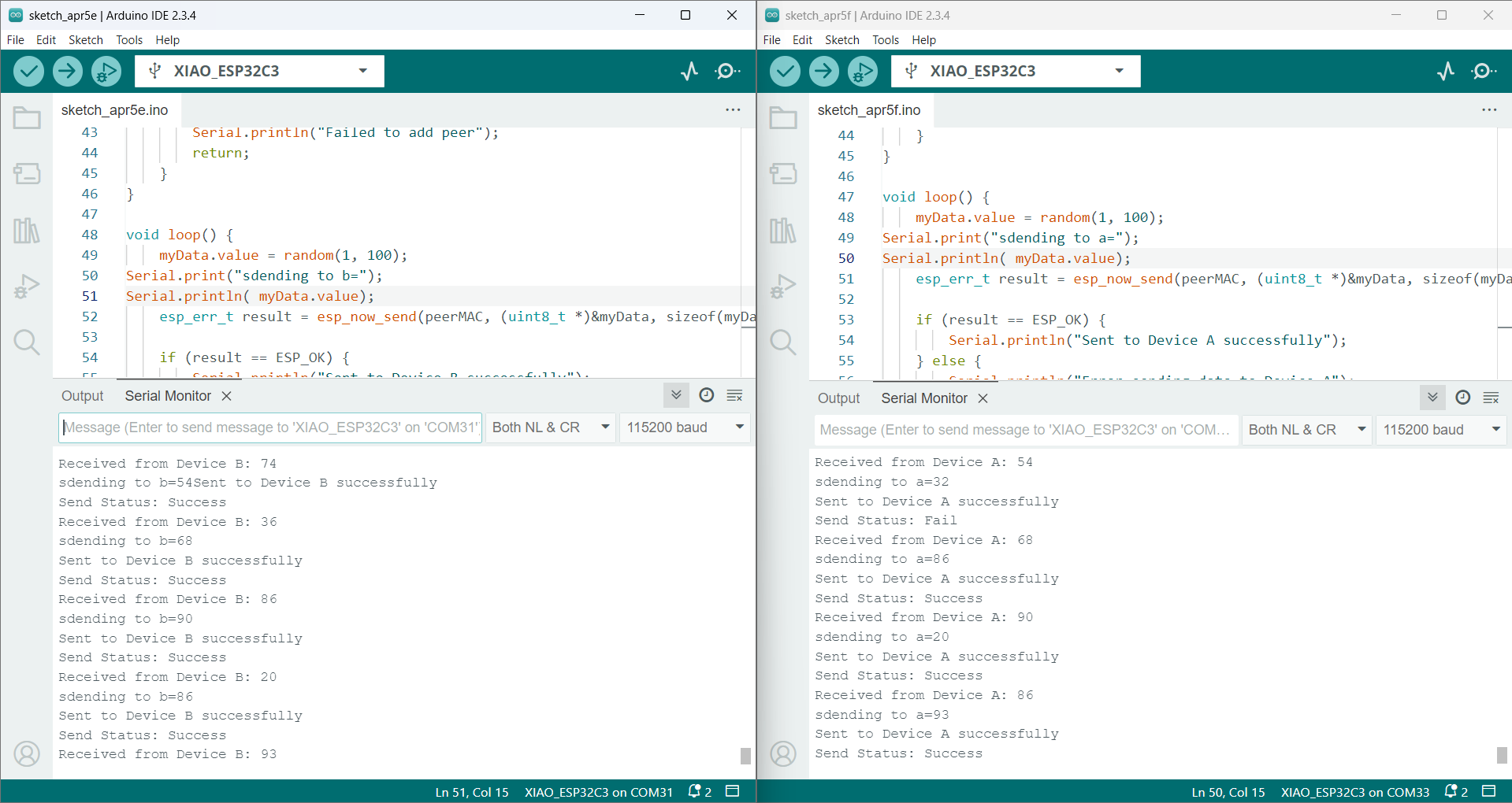
We successfully verified and uploaded the code. Both devices are now able to send random data to each other. Now, I can also send my sensor data from one device to another.
Testing the Current Sensor
In our group, we discussed the idea of transmitting data wirelessly using a sensor, with the goal of displaying or showing that the data had been successfully sent. We chose to use a current sensor to address this. Before implementing the sensor, we first researched its code, established the necessary connections, and then conducted tests to ensure everything worked correctly.
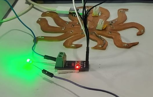
We connected the sensor with a power supply and added a 3.3V LED to help visualize the current flow.
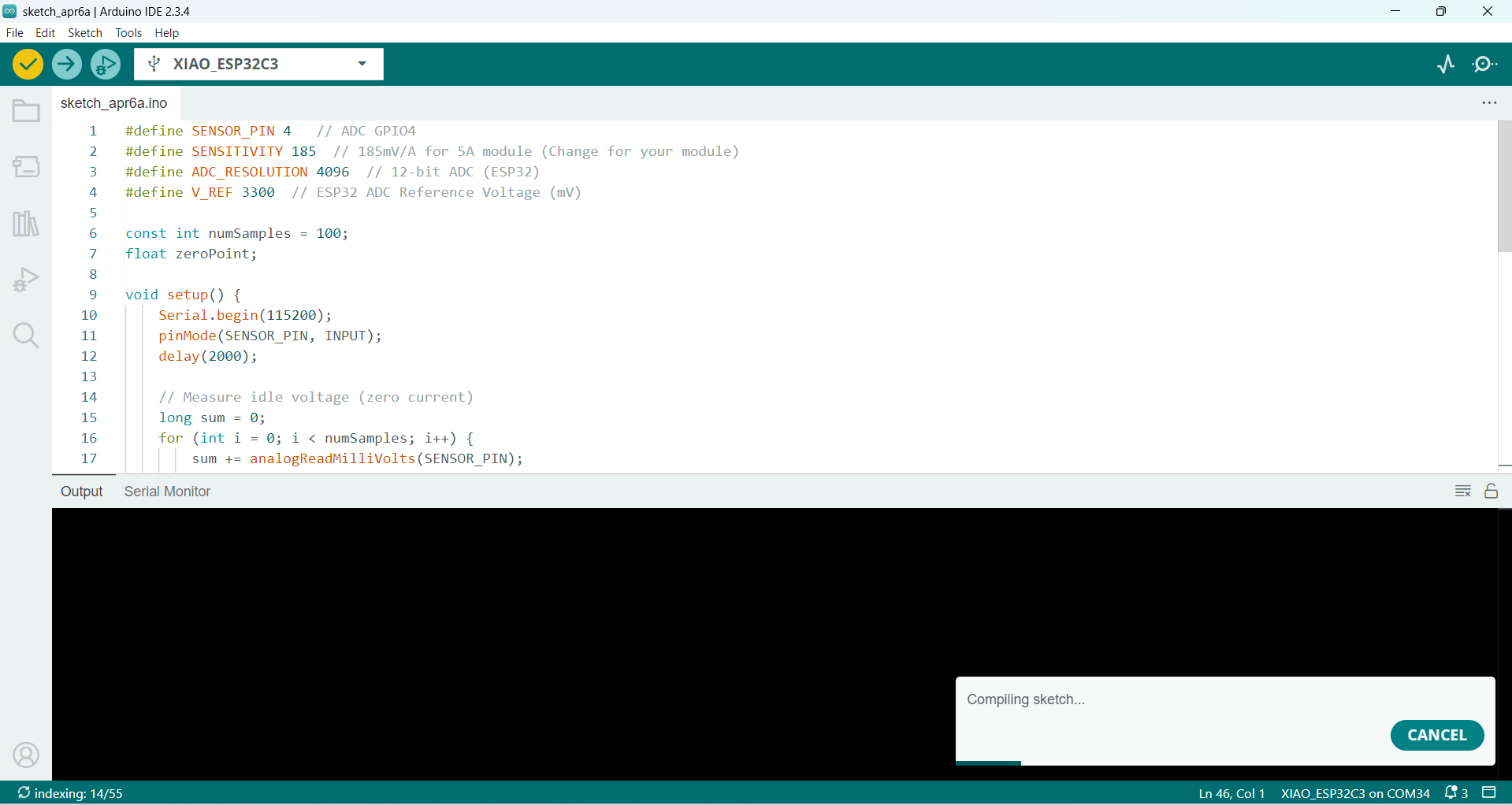
We verified the code successfully:
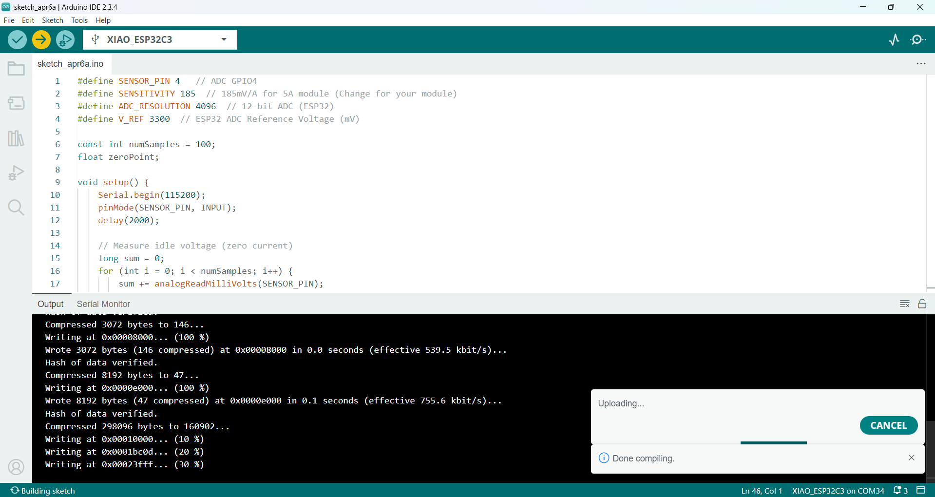
Then, We uploaded the code to the board:
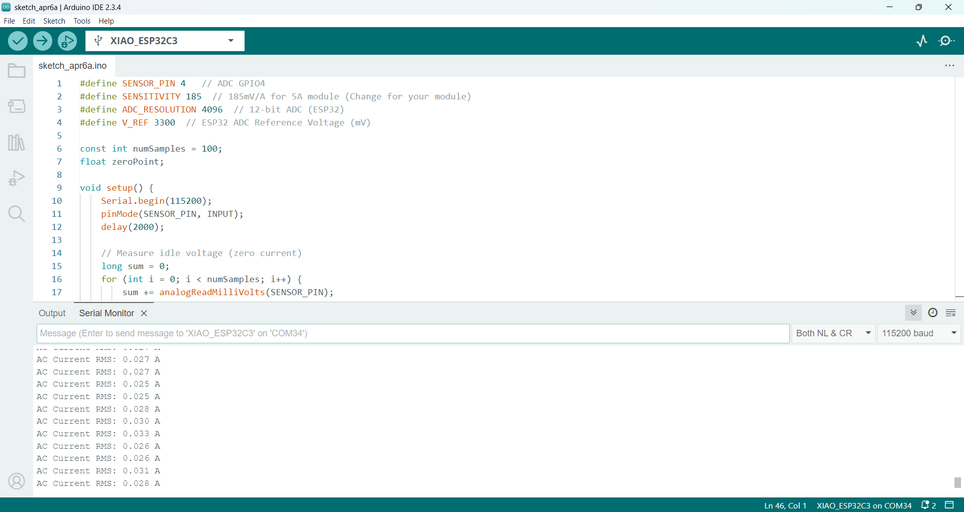
Once the code was uploaded, the current readings began to appear on the Serial Monitor. Initially, the current sensor did not provide accurate readings. we made some modifications in the code, which significantly improved the accuracy of the measurements.
#define SENSOR_PIN 4   // ADC GPIO4
#define SENSITIVITY 185  // 185mV/A for 5A module (Change for your module)
#define ADC_RESOLUTION 4096  // 12-bit ADC (ESP32)
#define V_REF 3300  // ESP32 ADC Reference Voltage (mV)

const int numSamples = 100;
float zeroPoint;

void setup() {
    Serial.begin(115200);
    pinMode(SENSOR_PIN, INPUT);
    delay(2000);

    // Measure idle voltage (zero current)
    long sum = 0;
    for (int i = 0; i < numSamples; i++) {
        sum += analogReadMilliVolts(SENSOR_PIN);
        delay(10);
    }
    zeroPoint = sum / numSamples;
    Serial.print("Zero Point (No Current): ");
    Serial.print(zeroPoint);
    Serial.println(" mV");
}

float readACCurrent() {
    float sumSquared = 0;

    for (int i = 0; i < numSamples; i++) {
        float voltage = analogReadMilliVolts(SENSOR_PIN);
        float current = (voltage - zeroPoint) / SENSITIVITY;
        sumSquared += current * current;
        delay(1);
    }

    return sqrt(sumSquared / numSamples);
}

void loop() {
    float acCurrent = readACCurrent();
    Serial.print("AC Current RMS: ");
    Serial.print(acCurrent, 3);
    Serial.println(" A");
    delay(1000);
}
For this group assignment, we focused on wireless communication using the Xiao ESP32-C3 microcontroller. Our objective was to transmit current sensor data from one board to another via basic wireless communication. Additionally, we displayed the received data on an OLED screen and evaluated the current sensor's response.
Components Used:
- 2x Xiao ESP32-C3 Boards
- 1x Current Sensor (D2)
- 1x OLED Display (SDA, SCL)
- Power Supply (for Current Sensor)
| S.No | Component | Pin on Component (Board A) | Pin on Xiao ESP32-C3 (Board A) | Description |
|---|---|---|---|---|
| 1 | Current Sensor | VCC | 3.3V or 5V | Power supply to current sensor on Board A |
| 2 | Current Sensor | GND | GND | Common ground for Board A |
| 3 | Current Sensor | OUT | A2 | Signal pin from current sensor to analog input (A2) on Board A |
| 4 | Wi-Fi Communication | - | - | Wireless communication via Wi-Fi (sends current sensor data) |
| S.No | Component | Pin on Component (Board B) | Pin on Xiao ESP32-C3 (Board B) | Description |
|---|---|---|---|---|
| 1 | OLED Display (I2C) | SDA | D4 | I2C data line for OLED on Board B |
| 2 | OLED Display (I2C) | SCL | D5 | I2C clock line for OLED on Board B |
| 3 | OLED Display (I2C) | VCC | 3.3V | Power to OLED on Board B |
| 4 | OLED Display (I2C) | GND | GND | Common ground for Board B |
| 5 | Wi-Fi Communication | - | - | Wireless communication via Wi-Fi (receives current sensor data) |
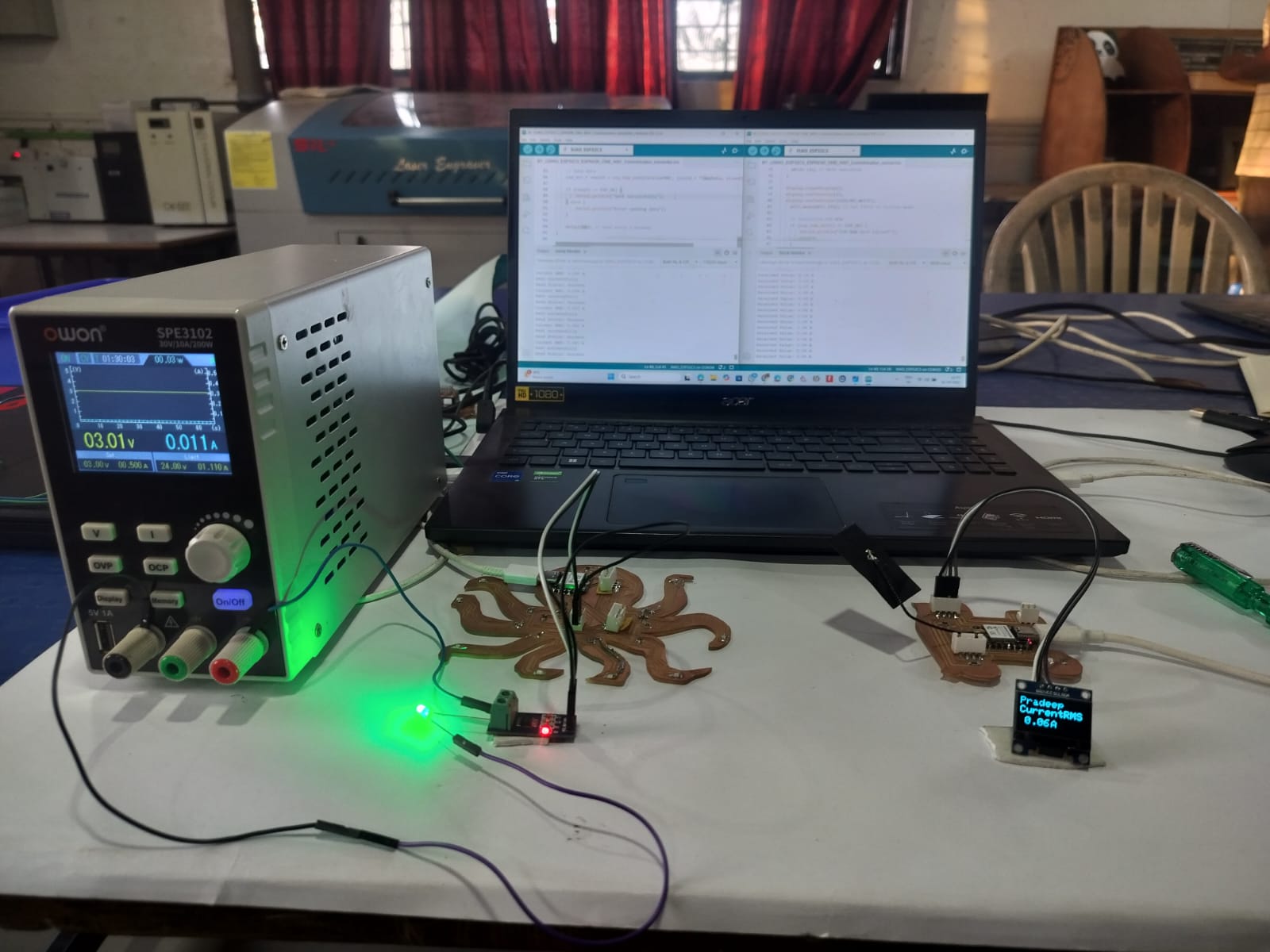
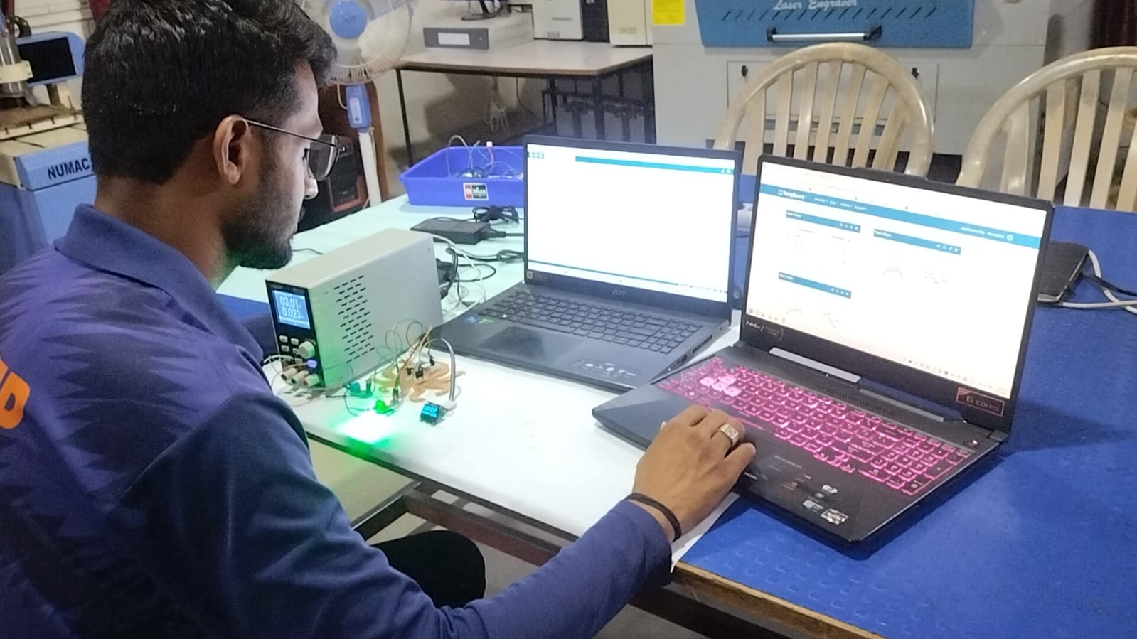
We connected two Xiao ESP32-C3 boards as per the provided connection table. The current sensor and OLED display were connected using the SDA and SCL pins. To test the system, a 3-watt LED was used. The current sensor was powered through the power supply.
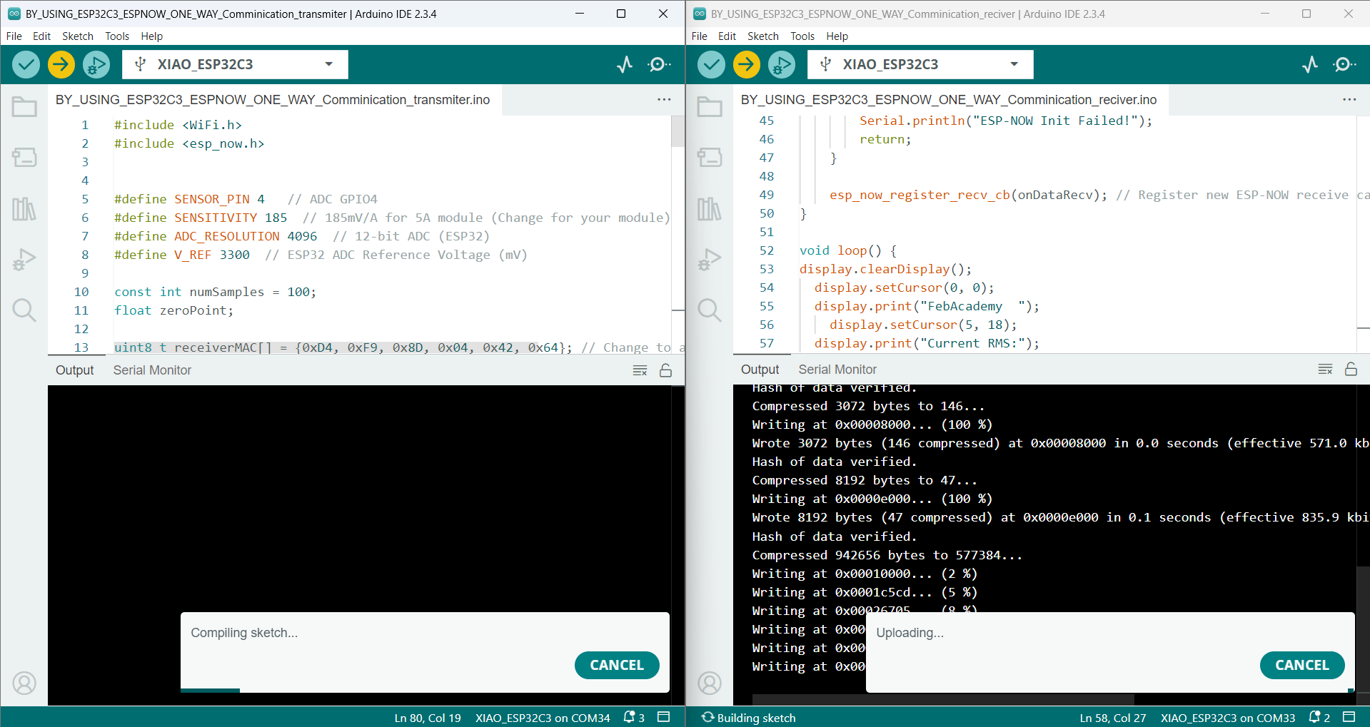
We included my current sensor and OLED code within the existing transmit and receive code. After adding the code, We verified and uploaded it to the board
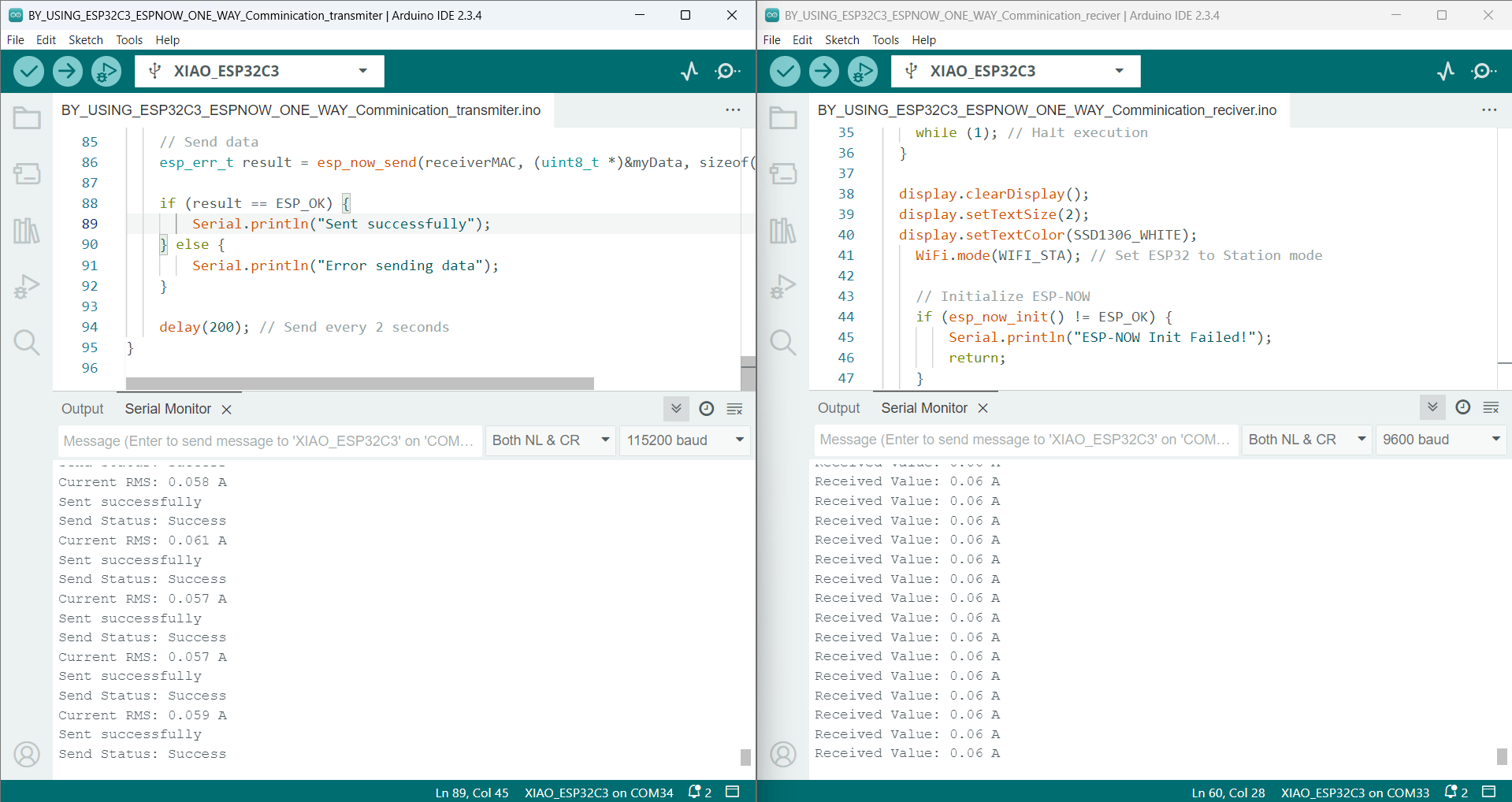
The current sensor data started transferring successfully to the other board, and the OLED indicated that the communication was working properly.
To check the current sensor readings, We used a 3-watt LED to measure the current flowing through it. This setup is shown in the video. The data is successfully transmitted from one device to another, and the LED output also reflects the data transfer.
#include WiFi.h
#include esp_now.h


#define SENSOR_PIN 4   // ADC GPIO4
#define SENSITIVITY 185  // 185mV/A for 5A module (Change for your module)
#define ADC_RESOLUTION 4096  // 12-bit ADC (ESP32)
#define V_REF 3300  // ESP32 ADC Reference Voltage (mV)

const int numSamples = 100;
float zeroPoint;

uint8_t receiverMAC[] = {0xD4, 0xF9, 0x8D, 0x04, 0x42, 0x64}; // Change to actual receiver MAC

// Data structure to send
typedef struct struct_message {
     float value;
} struct_message;

struct_message myData;

// Callback when data is sent
void onDataSent(const uint8_t *mac_addr, esp_now_send_status_t status) {
    Serial.print("Send Status: ");
    Serial.println(status == ESP_NOW_SEND_SUCCESS ? "Success" : "Fail");
}

void setup() {
    Serial.begin(115200);
  pinMode(SENSOR_PIN, INPUT);
    delay(500);

    // Measure idle voltage (zero current)
    long sum = 0;
    for (int i = 0; i < numSamples; i++) {
        sum += analogReadMilliVolts(SENSOR_PIN);
        delay(10);
    }
    zeroPoint = sum / numSamples;
    Serial.print("Zero Point (No Current): ");
    Serial.print(zeroPoint);
    Serial.println(" mV");
    WiFi.mode(WIFI_STA); // Set ESP32 to Station mode

    // Initialize ESP-NOW
    if (esp_now_init() != ESP_OK) {
        Serial.println("ESP-NOW Init Failed!");
        return;
    }

    esp_now_register_send_cb(onDataSent);

    // Register peer
    esp_now_peer_info_t peerInfo = {};
    memcpy(peerInfo.peer_addr, receiverMAC, 6);
    peerInfo.channel = 0;
    peerInfo.encrypt = false;

    if (esp_now_add_peer(&peerInfo) != ESP_OK) {
        Serial.println("Failed to add peer");
        return;
    }
}

float readACCurrent() {
    float sumSquared = 0;

    for (int i = 0; i < numSamples; i++) {
        float voltage = analogReadMilliVolts(SENSOR_PIN);
        float current = (voltage - zeroPoint) / SENSITIVITY;
        sumSquared += current * current;
        delay(1);
    }

    return sqrt(sumSquared / numSamples);
}

void loop() {
    float acCurrent = readACCurrent();
    Serial.print("Current R
    MS: ");
    Serial.print(acCurrent, 3);
    Serial.println(" A");
    myData.value =acCurrent;

    // Send data
    esp_err_t result = esp_now_send(receiverMAC, (uint8_t *)&myData, sizeof(myData));

    if (result == ESP_OK) {
        Serial.println("Sent successfully");
    } else {
        Serial.println("Error sending data");
    }

    delay(200); // Send every 2 seconds
}
 #include WiFi.h
#include esp_now.h
#include Wire.h
#include Adafruit_GFX.h
#include Adafruit_SSD1306.h

// OLED display width and height
#define SCREEN_WIDTH 128
#define SCREEN_HEIGHT 64

// Create display object
Adafruit_SSD1306 display(SCREEN_WIDTH, SCREEN_HEIGHT, &Wire, -1);

// Structure to receive data
typedef struct struct_message {
     float value;
} struct_message;

struct_message myData;

// New ESP-IDF v5.x compatible callback
void onDataRecv(const esp_now_recv_info_t *info, const uint8_t *incomingData, int len) {
    memcpy(&myData, incomingData, sizeof(myData));
    Serial.print("Received Value: ");
    Serial.print(myData.value);
    Serial.println(" A");

}

void setup() {
    Serial.begin(115200);
 // Initialize OLED display
  if (!display.begin(SSD1306_SWITCHCAPVCC, 0x3C)) { // 0x3C is the I2C address
    Serial.println(F("SSD1306 allocation failed"));
    while (1); // Halt execution
  }

  display.clearDisplay();
  display.setTextSize(2);
  display.setTextColor(SSD1306_WHITE);
    WiFi.mode(WIFI_STA); // Set ESP32 to Station mode

    // Initialize ESP-NOW
    if (esp_now_init() != ESP_OK) {
        Serial.println("ESP-NOW Init Failed!");
        return;
    }

    esp_now_register_recv_cb(onDataRecv); // Register new ESP-NOW receive callback
}

void loop() {
display.clearDisplay();
  display.setCursor(0, 0);
  display.print("Pradeep");
    display.setCursor(0, 18);
  display.print("CurrentRMS");
      display.setCursor(10, 40);
  display.print(myData.value);
        display.setCursor(60, 40);
  display.print("A");
  display.display();
    // Do nothing, waiting for ESP-NOW messages
}