Mini AgriSun Trap
Introduction
Mini – Indicates that the device is small, lightweight, and easy to carry or install, suitable for limited spaces like small farms or gardens.
Agri – Refers to agriculture, showing that the device is meant for use in farming or crop protection.
Sun – Highlights that the device runs on solar energy, making it eco-friendly and usable in off-grid rural areas.
Trap – Explains the function of the device: to capture or eliminate harmful insects that damage crops.
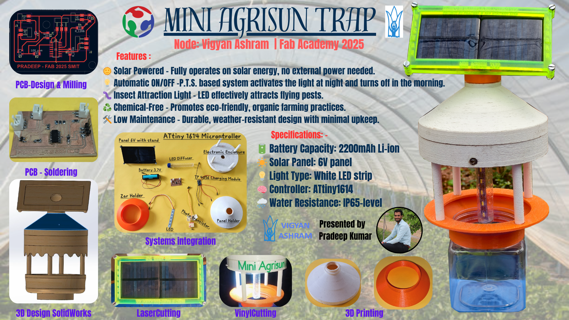
Final Product slide
An environmentally friendly and solar-powered device, the solar insect trap is designed to attract and capture flying insects using light. This innovative solution specifically targets harmful agricultural pests such as thrips, mites, whiteflies, and red spiders, which are known to cause significant damage to crops. By reducing the dependence on chemical pesticides, these traps offer a sustainable and eco-conscious alternative for pest control, helping to preserve soil health and protect biodiversity.
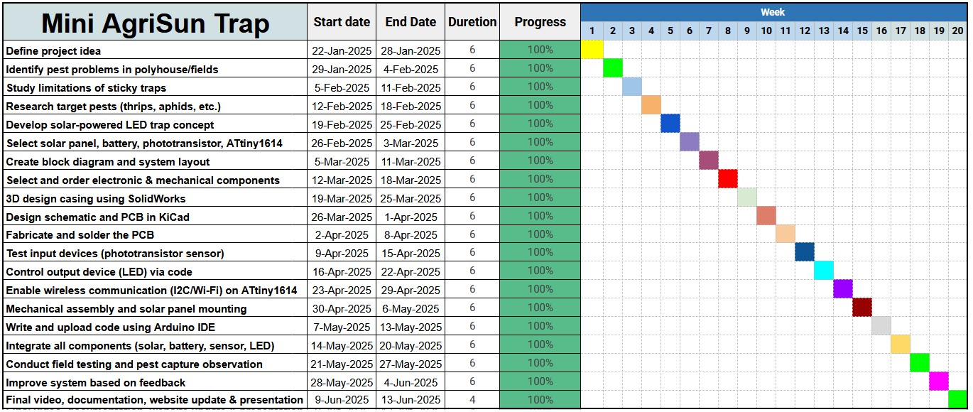
Gantt Chart
My final project was developed according to a well-defined Gantt chart, which guided the entire workflow and ensured systematic progress from the initial planning phase to the final execution
Problem Statement
At Vigyan Ashram, both polyhouses and open agricultural fields are severely affected by the uncontrolled spread of pests such as thrips, whiteflies, aphids, and fruit flies. This persistent infestation significantly lowers crop productivity and compromises the overall quality of the produce. Conventional pest control practices, which primarily rely on chemical pesticides, have several drawbacks. Not only do they contribute to the development of pesticide-resistant pest strains, but they also pose serious threats to the environment, beneficial insect populations, and human health.
In light of these challenges, there is an urgent need for an integrated, environmentally sustainable, and technologically advanced pest management system. Such a system should provide real-time monitoring and early detection capabilities, enabling farmers to manage pest populations more effectively and ensure long-term agricultural sustainability and profitability.
During a discussion with a staff member at Vigyan Ashram, I learned that their current approach involves the use of blue and yellow sticky traps, which attract and capture specific types of insects. Additionally, they occasionally apply pesticides, although this method offers only limited and temporary relief from pest problems. These insights further emphasize the necessity of developing an improved, data-driven, and eco-friendly solution to address pest-related issues in modern agriculture.
| S.N |
Name |
Scientific Name |
Description |
Link |
| 1 |
Thrips |
Frankliniella spp. |
Small insects that feed on plant tissues, causing silvering and distortion. |
Thrips |
| 2 |
Whiteflies |
Trialeurodes vaporariorum |
Tiny white insects that suck sap and can transmit plant viruses. |
Whiteflies |
| 3 |
Aphids |
Aphididae family |
Soft-bodied insects that feed on plant sap, leading to curled leaves and stunted growth. |
Aphids |
| 4 |
Leafhoppers |
Cicadellidae family |
Wedge-shaped insects that feed on plant sap and can transmit diseases. |
Leafhoppers |
| 5 |
Fruit Flies |
Tephritidae family |
Flies whose larvae infest fruits, causing decay and crop loss. |
Fruit Flies |
| 6 |
Moths |
Lepidoptera order |
Adult moths lay eggs; larvae (caterpillars) feed on plant foliage. |
Moths |
| 7 |
Leafminers |
Agromyzidae family |
Larvae create tunnels inside leaves, reducing photosynthetic ability. |
Leafminers |
| 8 |
Fungus Gnats |
Bradysia spp. |
Small flies; larvae feed on roots and organic matter in soil. |
Fungus Gnats |
| 9 |
Sciarid Flies |
Bradysia paupera |
Also known as fungus gnats; larvae damage roots and seedlings. |
Sciarid Flies |
| 10 |
Cucumber Beetles |
Diabrotica spp. |
Beetles that feed on leaves, stems, and roots, transmitting diseases. |
Cucumber Beetles |
Through this project, my goal was to explore innovative and eco-friendly methods to eliminate these pests and ensure better protection for the plants grown inside the polyhouse.
Online Survey on Insect Control Devices in India
To effectively address the challenges faced by farmers due to insect pests, I conducted an extensive survey focusing on the available insect control devices in the market. I carefully studied various products to understand their features, usability, and costs. The objective is not merely to create a prototype but to develop a fully operational, affordable research and development (R&D) product that farmers can purchase, assemble, and operate independently without requiring specialized technical skills. This approach aims to enhance accessibility and promote sustainable agricultural practices across India.
Popular Insect Control Devices Available Online
Market Analysis of Existing Solar Insect Traps in India
| Brand/Product |
Price (INR) |
Key Features |
Purchase Link |
| Chipku Mini Solar Insect Trap |
₹1,149 |
LED light, solar-powered, environmentally friendly |
Buy Here |
| Wavar Mini Solar Insect Light Trap |
₹1,419 |
3W solar panel, 2000 mAh battery, UV LEDs for insect attraction |
Buy Here |
| Ugaoo Mini Solar Light Insect Trap |
₹1,499 |
Effective coverage of 1 to 1.5 acres, eco-friendly design |
Buy Here |
| Farmroot Solar Insect Trap |
₹3,500 |
12V/10W solar panel with 12V–7AH battery, robust performance |
Buy Here |
| BuzzZap Mini Solar Light Insect Trap |
₹5,500 |
5W solar panel, 7.2V 2.5AH Li-Ion battery, portable design |
Buy Here |
Proposed Low-Cost Solar Insect Trap: Detailed Cost Analysis
| Component |
Estimated Cost (INR) |
Purpose / Description |
| Solar Panel (3W) |
₹120 |
Harnesses sunlight to recharge the battery |
| Rechargeable Battery (3.7V, 2000 mAh) |
₹55 |
Powers the UV LED lights throughout the night |
| LED Lights |
₹30 |
Attracts flying insects effectively |
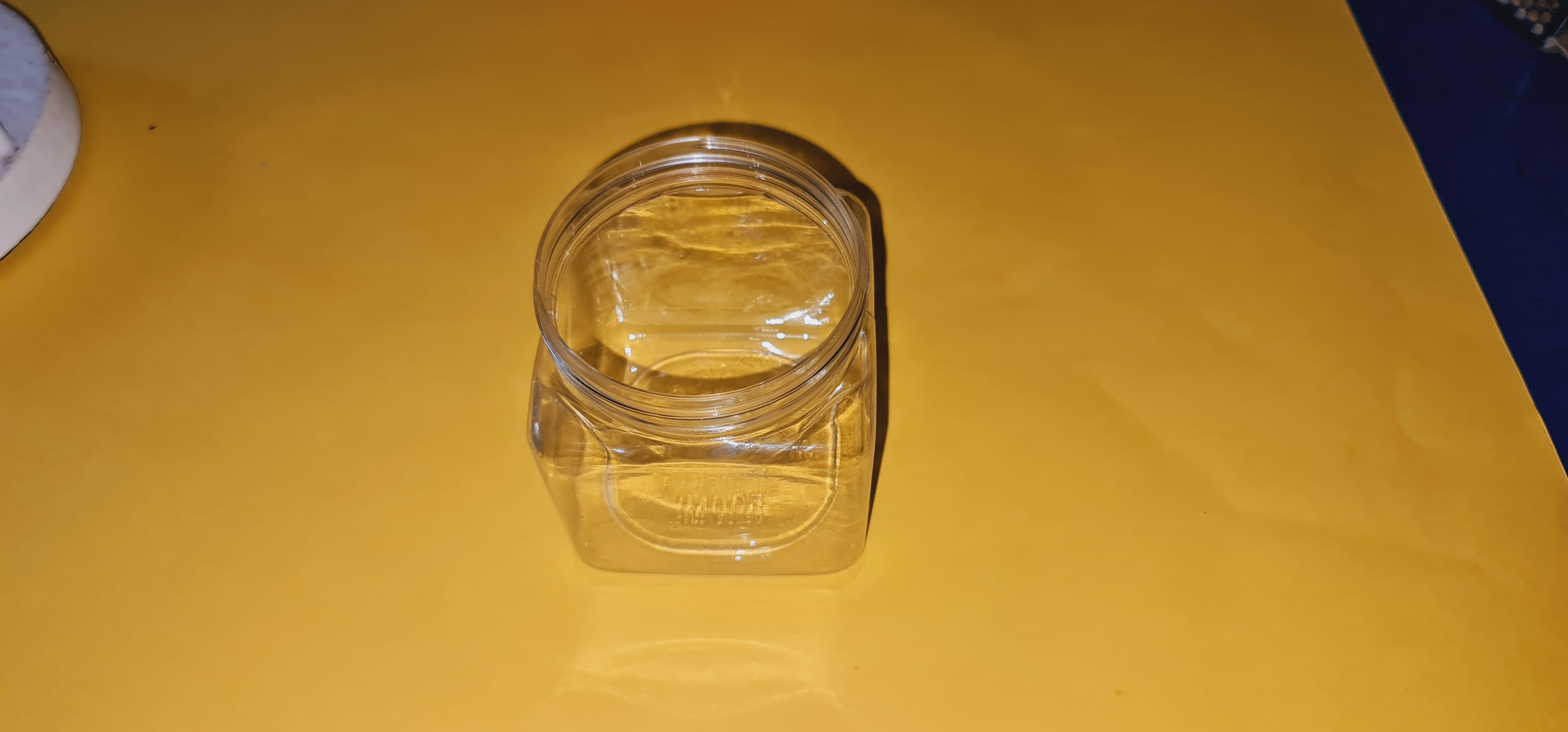
| Plastic Housing and Collection Tray |
₹150 |
Protective casing and insect trap container |
| Basic Circuit Components |
₹100 |
Includes resistors, wiring, switches for basic control |
| Assembly and Miscellaneous Expenses |
₹50 |
Labor, adhesives, and packaging costs |
| Total Estimated Cost |
₹505 |
— |
Justification for a ₹600 Price Point
- Affordable for Small Farmers: By sourcing components locally and maintaining a simple design, the product can be sold at ₹600 with a reasonable profit margin.
- Market Competitiveness: This price point fills a gap between low-cost ineffective options and high-end costly devices priced between ₹1,100 to ₹5,500.
- Eco-Friendly Technology: Operates entirely on solar power, eliminating the need for harmful chemicals and promoting sustainability.
- User-Centric Design: Easy to install, operate, and maintain, requiring no advanced technical knowledge from users.
Conclusion
Developing a solar insect trap priced under ₹600 is both practical and essential for empowering farmers in rural India. This product addresses pest control challenges sustainably and cost-effectively, providing a valuable tool to improve agricultural productivity and reduce dependency on chemical pesticides.
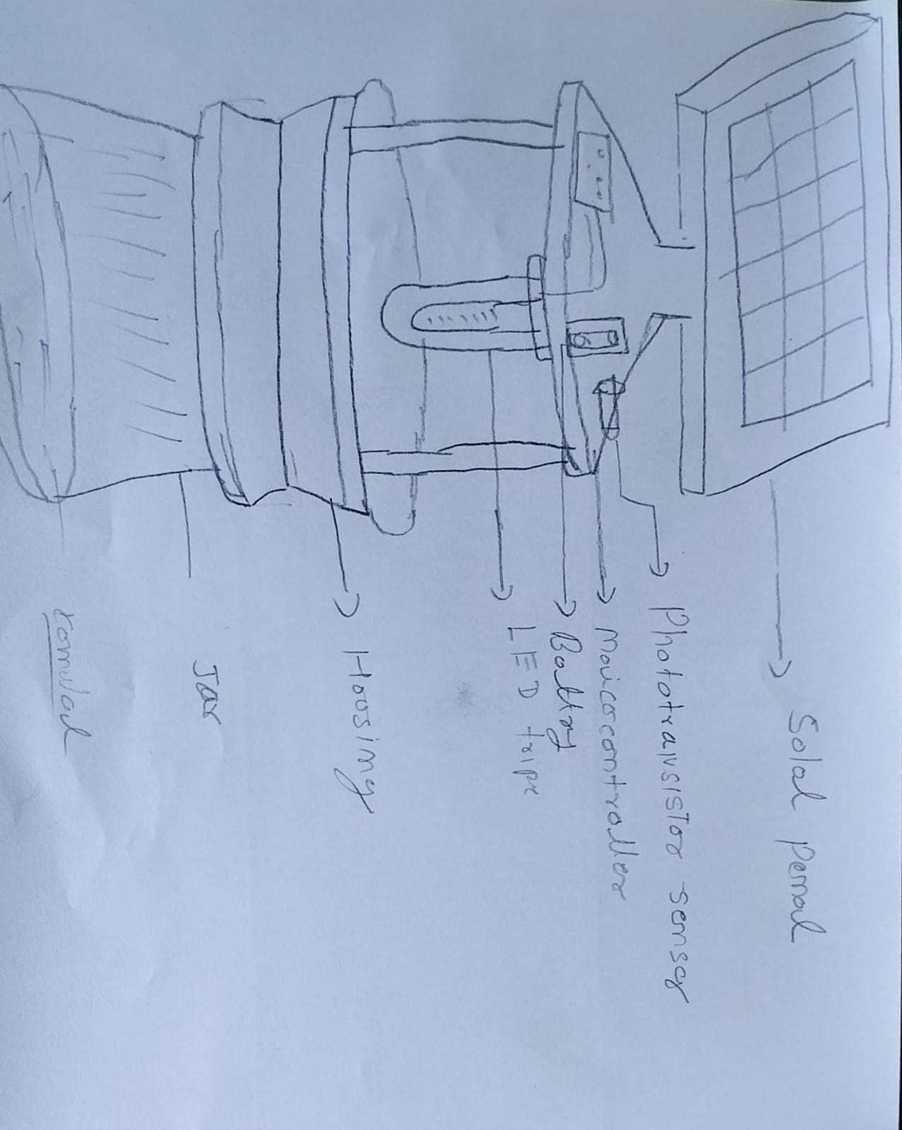
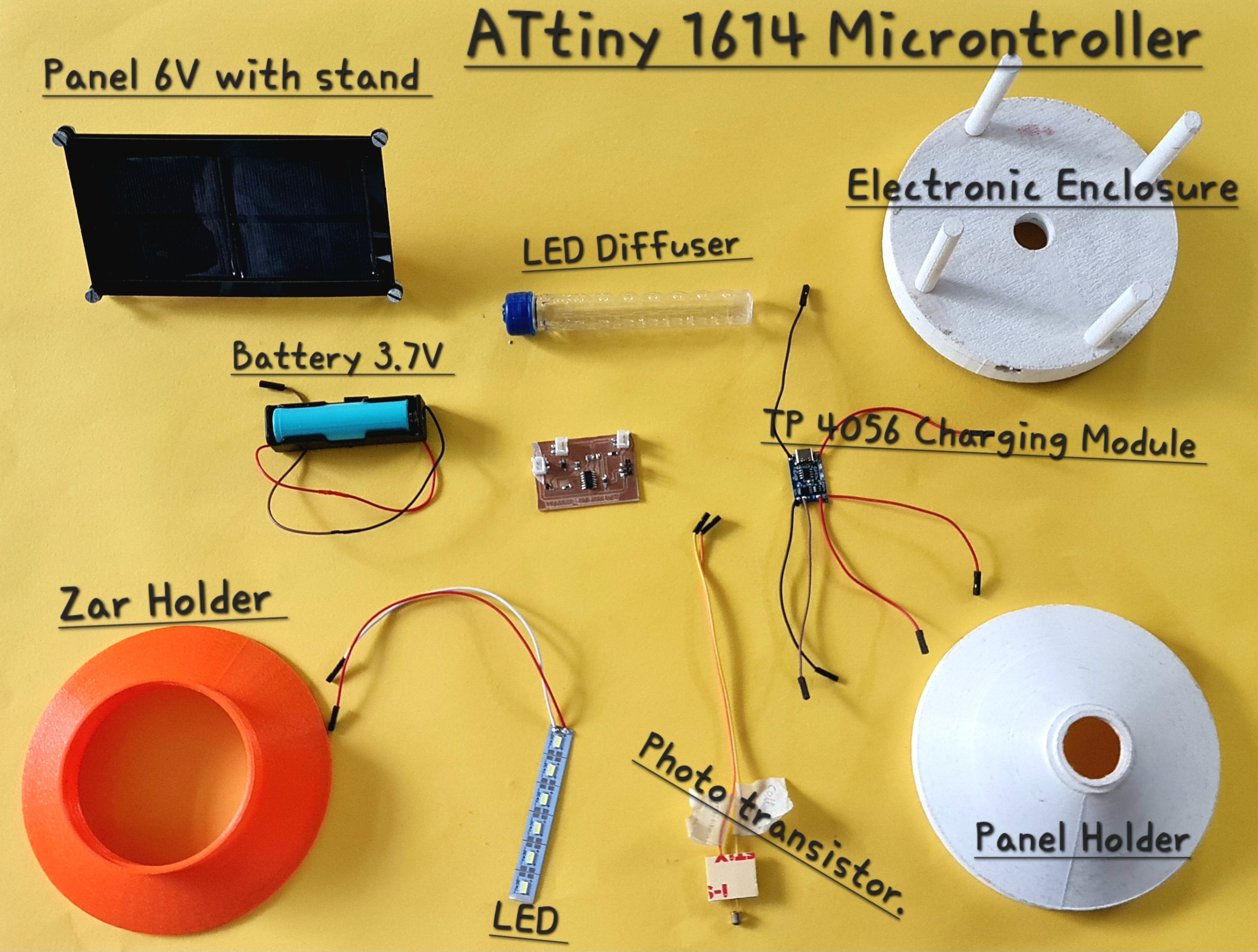
Solution with HandSketch
I have integrated various components such as a solar panel, LED strip, jar container, microcontroller, phototransistor sensor, and battery into a compact socket-based system. The entire setup has been carefully designed to fit within a small-sized enclosure, making it both efficient and space-saving.
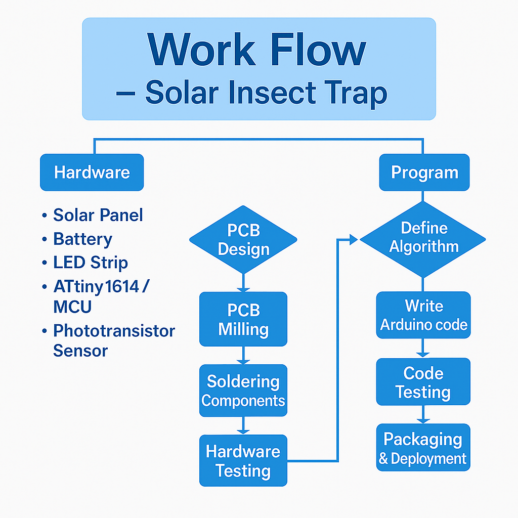
Work Flow – Mini AgriSun Trap (Solar Insect Trap)
The development of the Mini Aggression Trap (Solar Insect Trap) follows a structured and systematic workflow, divided into two main phases: hardware development and software programming.
In the hardware phase, the process begins with the collection of all essential components, such as the solar panel, rechargeable battery, LED strip, ATtiny1614 microcontroller, and a phototransistor sensor. Once the components are procured, the printed circuit board (PCB) is carefully designed, milled, and all components are soldered precisely onto the board. Detailed testing is then carried out to ensure all electrical connections and components are functioning correctly.
The software phase begins in parallel, starting with the development of a clear logic or algorithm that governs the operation of the insect trap. This logic is implemented using Arduino programming, followed by extensive testing to verify performance under various conditions.
After confirming the functionality of both the hardware and software, the final assembly of the device takes place. Each component is integrated into the final casing or housing, making the trap ready for real-world deployment.
This well-organized approach ensures the Mini Aggression Trap is efficient, durable, and suitable for practical use in outdoor environments.
| Hardware |
Mechanical Design |
Process Flow |
Program |
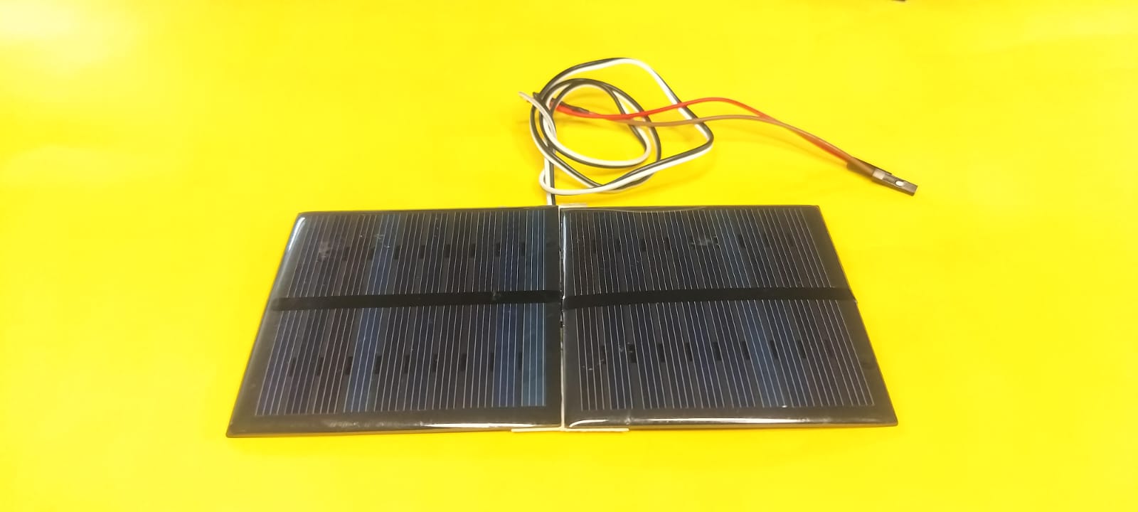
Solar Panel
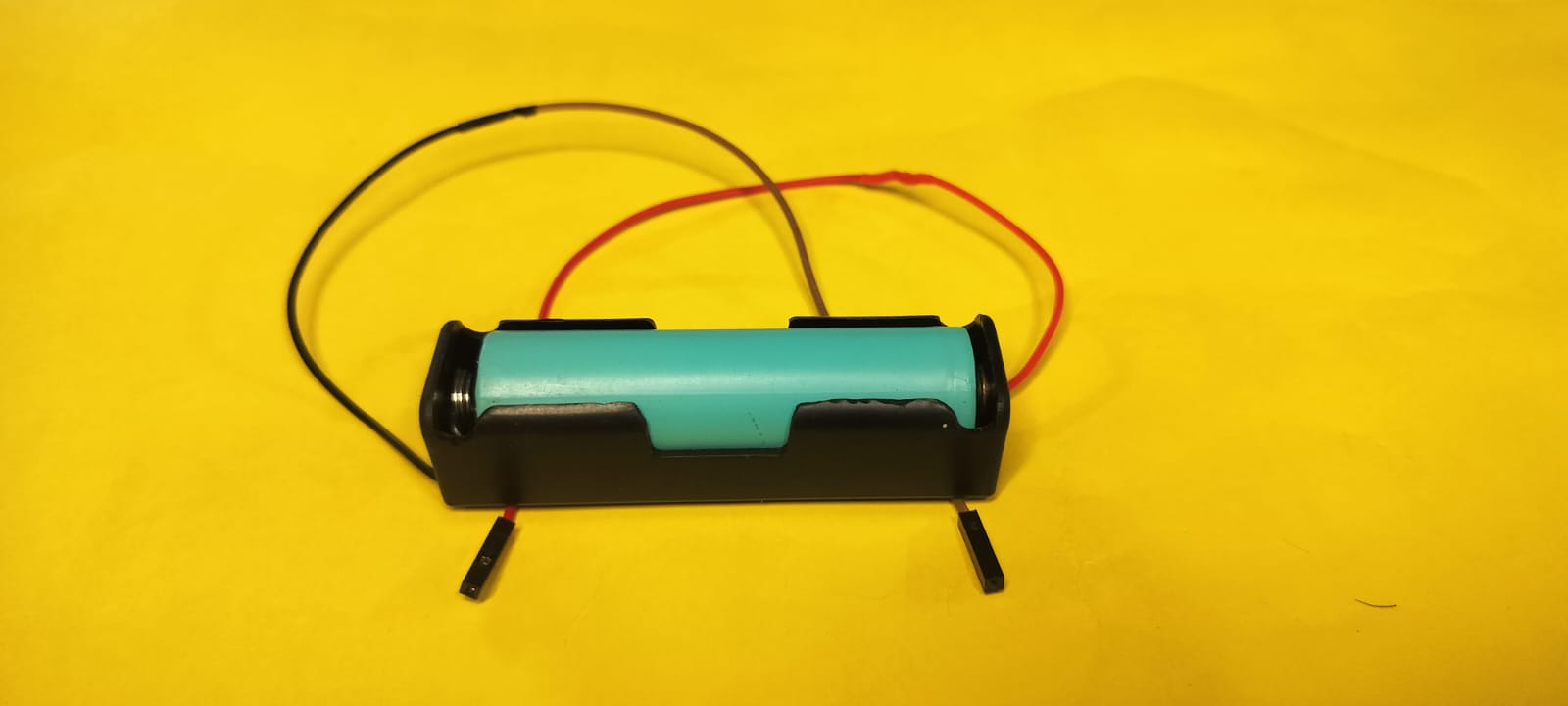
Battery
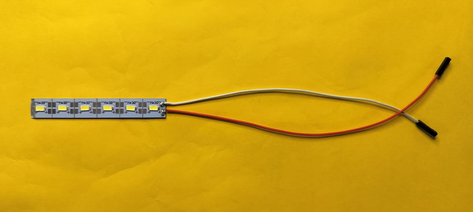
LED Strip
ATtiny1614 / Microcontroller
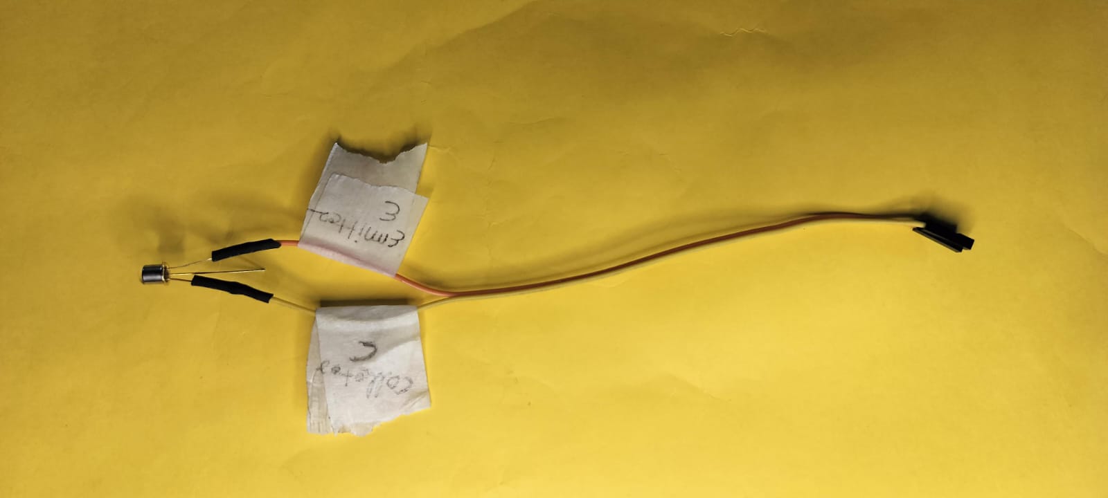
Phototransistor Sensor
|
3D Design of Components
3D Printing of Parts
|
PCB Design
PCB Milling
Soldering Components
Hardware Testing
|
Define Algorithm
Write Arduino Code
Code Testing
Packaging & Deployment
|
Hardware Assembly of My Project
The hardware assembly phase marked a critical milestone in my project development. It involved systematically organizing and integrating all essential components to ensure optimal functionality. I paid close attention to every connection, ensuring proper alignment, secure fittings, and full compatibility among the various parts.
Below is a list of the primary hardware components utilized in this project:
- Solar Panel – Captures solar energy to provide a renewable and eco-friendly power source for the system.
- Battery – Stores energy harvested from the solar panel, allowing the system to operate seamlessly even during periods without sunlight.
- LED Strip – Used for illumination or visual signaling, depending on the specific application requirements.
- ATtiny1614 Microcontroller – Functions as the brain of the system, executing programmed instructions and controlling peripheral devices.
- Phototransistor Sensor – Detects ambient light levels and sends input data to the microcontroller for responsive automation.
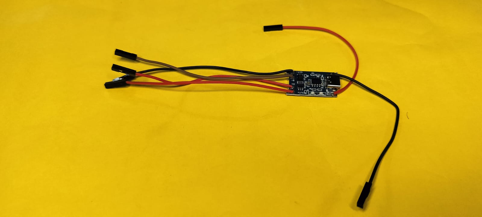
- TP4056 Module – A dedicated lithium battery charger that ensures safe, regulated charging from the solar input.
When integrated, these components form the backbone of my solar-powered solution. The combination of energy-efficient elements and intelligent control mechanisms supports both automation and sustainability. This assembly stage was essential in transforming the project's concept into a fully operational system.
I carefully assembled all the components, including the solar panel, battery, and charge controller, by following the circuit design. Special attention was given to proper soldering and insulation of the wires. After completing the assembly, I conducted multiple tests to confirm that each component was functioning as intended and that the system was stable under operating conditions.
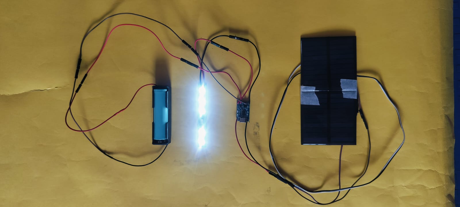
Once all the hardware elements were in place, I performed an individual test on each module to ensure correct behavior. After verifying the functionality of all components, I documented the entire process through a demonstration video. This video highlights the working setup and showcases the project in action.
After successfully completing the testing of all the components, I proceeded to develop the 3D design for my project.
PCB Design Process Using ATtiny1614
To design my PCB, I used the ATtiny1614 microcontroller, which is compact, efficient, and suitable for low-power embedded systems. Below is a step-by-step overview of my PCB fabrication process
Component list
ATtiny1614 IC
2× LED Pin Header
Phototransistor Sensor Pin Header
3-Pin Header for UPID
3-Pin Header for Extra Sensor
Resistor (10KΩ, 100Ω)
Diode
MOSFET
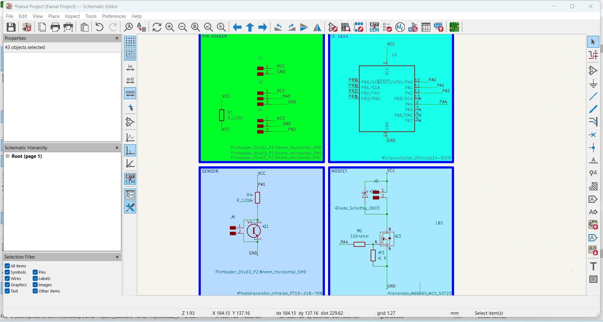
1. Created the Schematic Diagram:
I began by designing the complete schematic diagram of my circuit using KiCad. This step helped define all the electronic connections and components required.
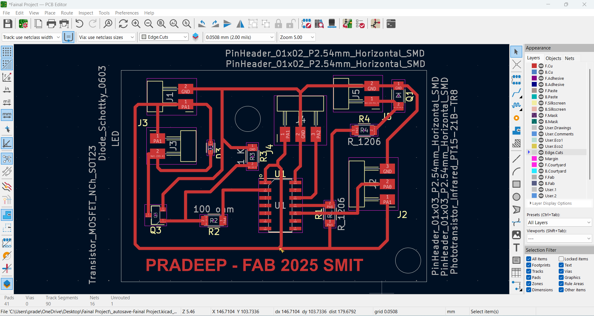
2. Performed PCB Routing in PCB Editor:
After finalizing the schematic, I moved to the PCB Editor to perform routing. I carefully routed all signal paths to avoid overlaps and ensured clean and efficient layout connections.
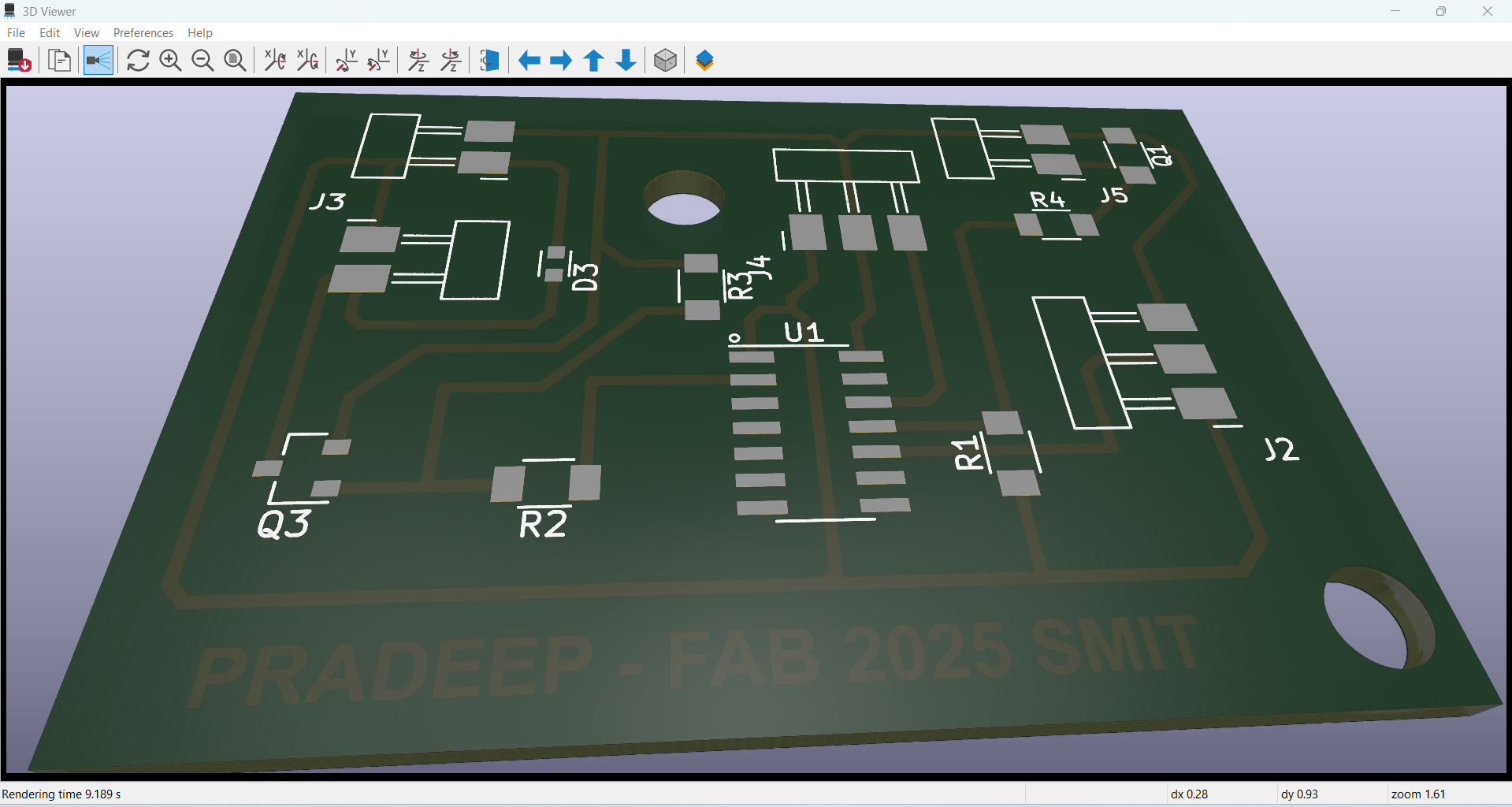
3. Viewed the 3D PCB Model:
Once the routing was complete, I generated a 3D view of the PCB. This allowed me to visually inspect component placements and ensure there were no conflicts or alignment issues.
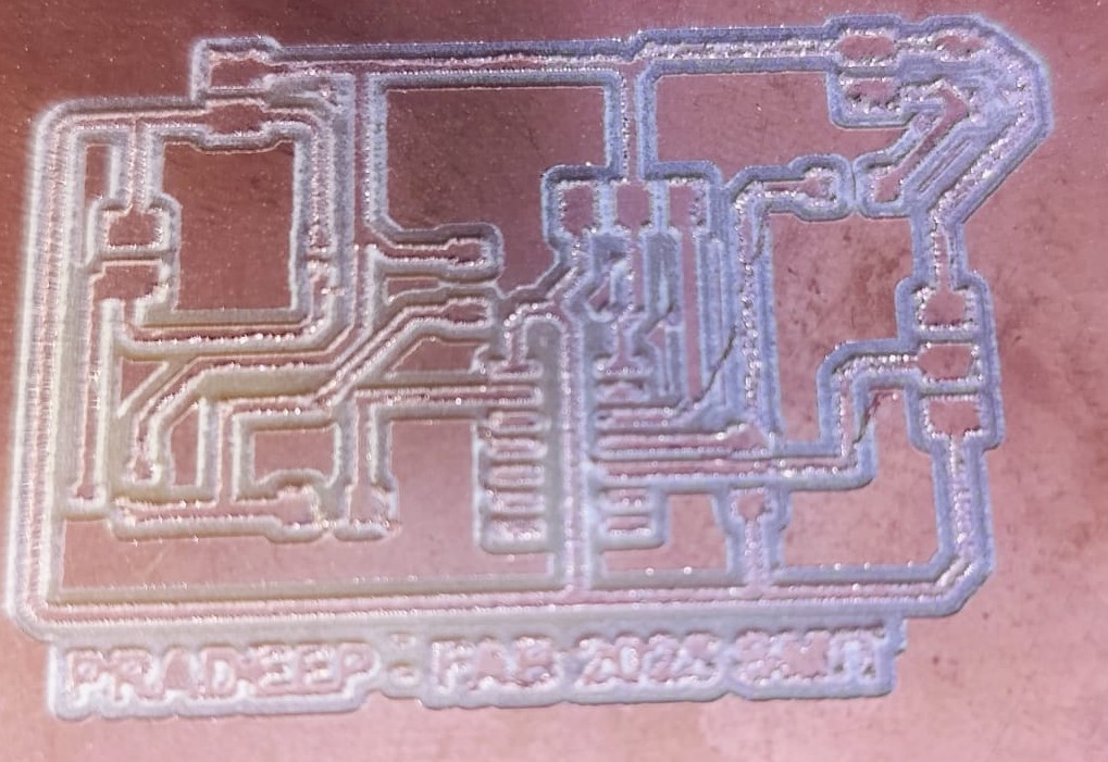
4. Performed Tracing with SRM-20 CNC Machine:
I used the SRM-20 CNC milling machine to trace the PCB layout onto the copper-clad board. The tracing process precisely carved out the paths required for the circuit.
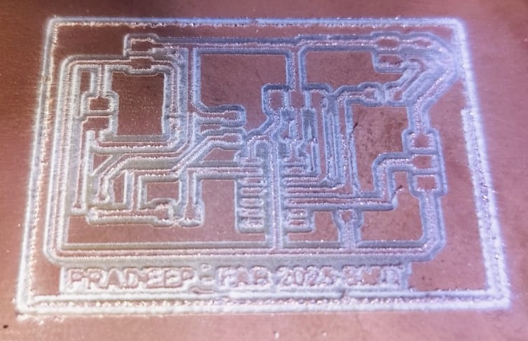
5. Applied Edge Cutting for Board Shaping:
To give the PCB its final shape and size, I used the edge-cutting feature. This step ensured the board was trimmed neatly and fit perfectly into its enclosure.
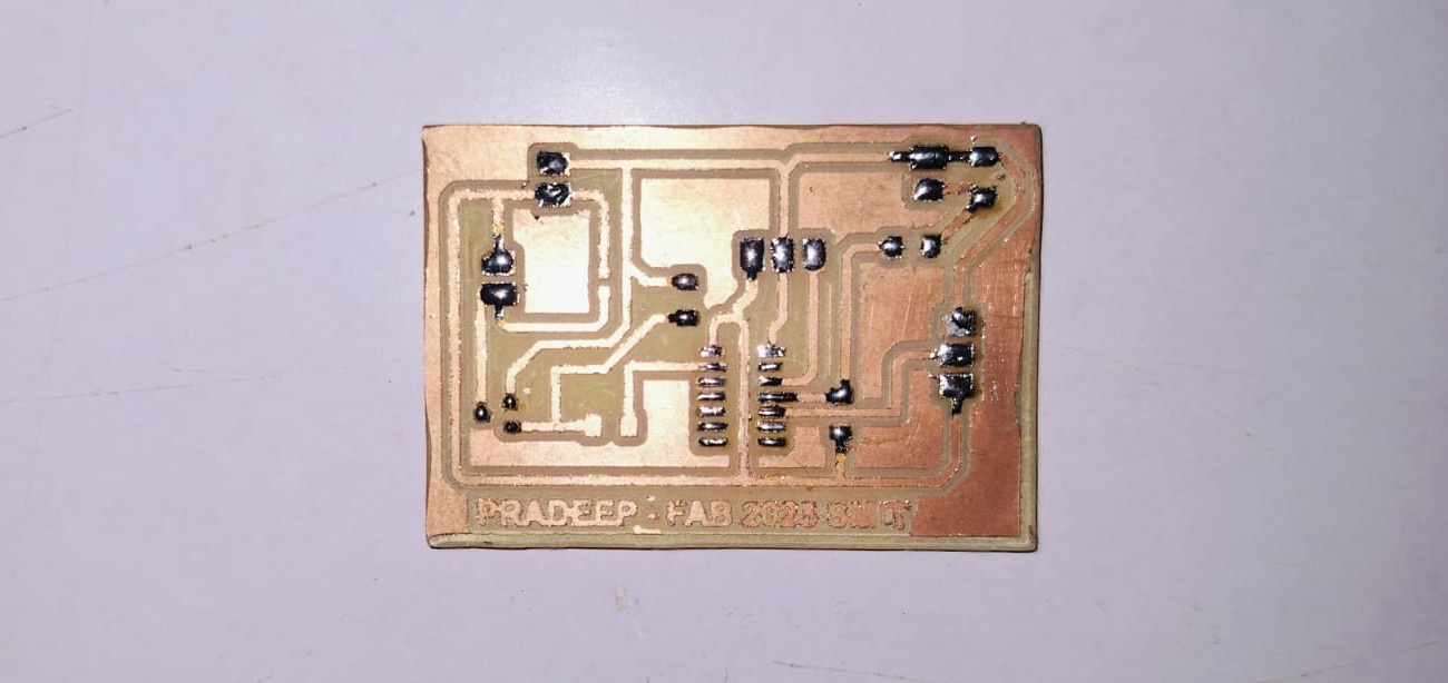
6. Applied Soldering Paste and Soldered the IC:
I applied soldering paste onto the PCB pads and then carefully placed and soldered the ATtiny1614 IC using a soldering iron.
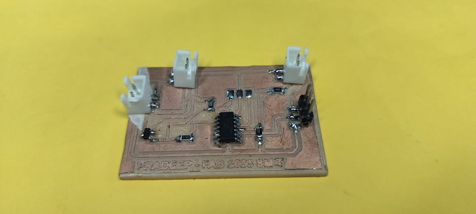
7. Soldered All Components to Complete the PCB:
Finally, I soldered all the remaining components onto the board. After checking all connections, my PCB was successfully completed and ready for testing.
Programming the Microcontroller Board
I successfully programmed the microcontroller board. The code was straightforward, and the programming process was completed smoothly. This step involved uploading the firmware to the custom board using the Arduino IDE and verifying that the board responded as expected.
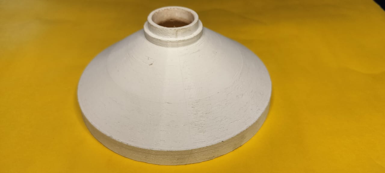
Final Product Design Thought Process
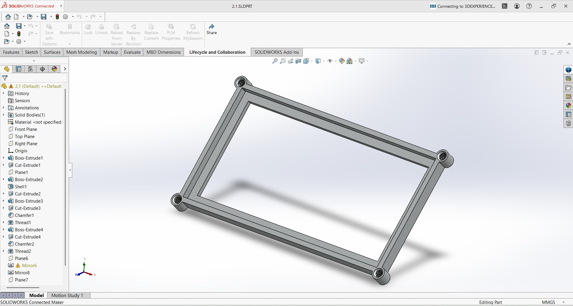
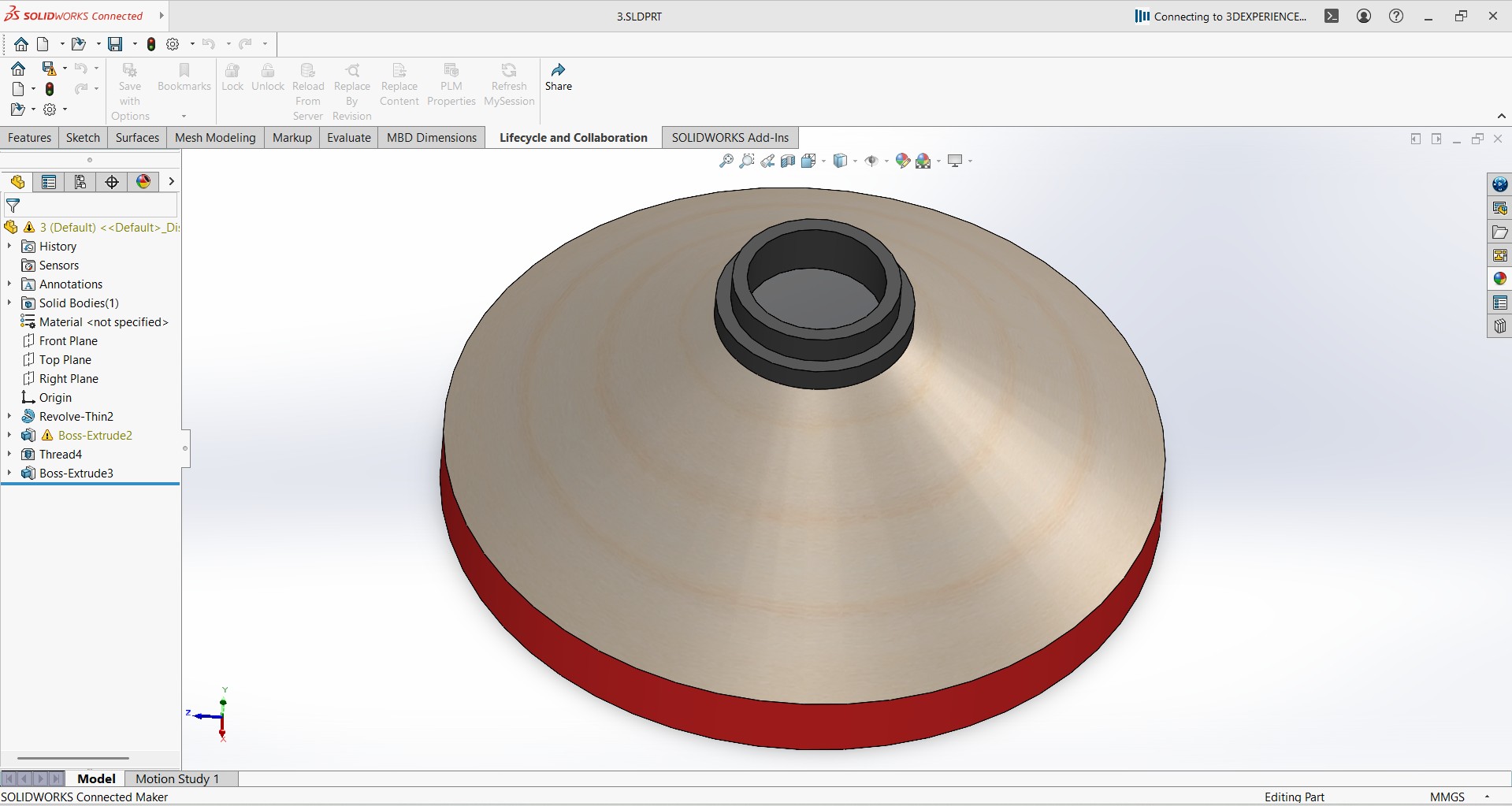
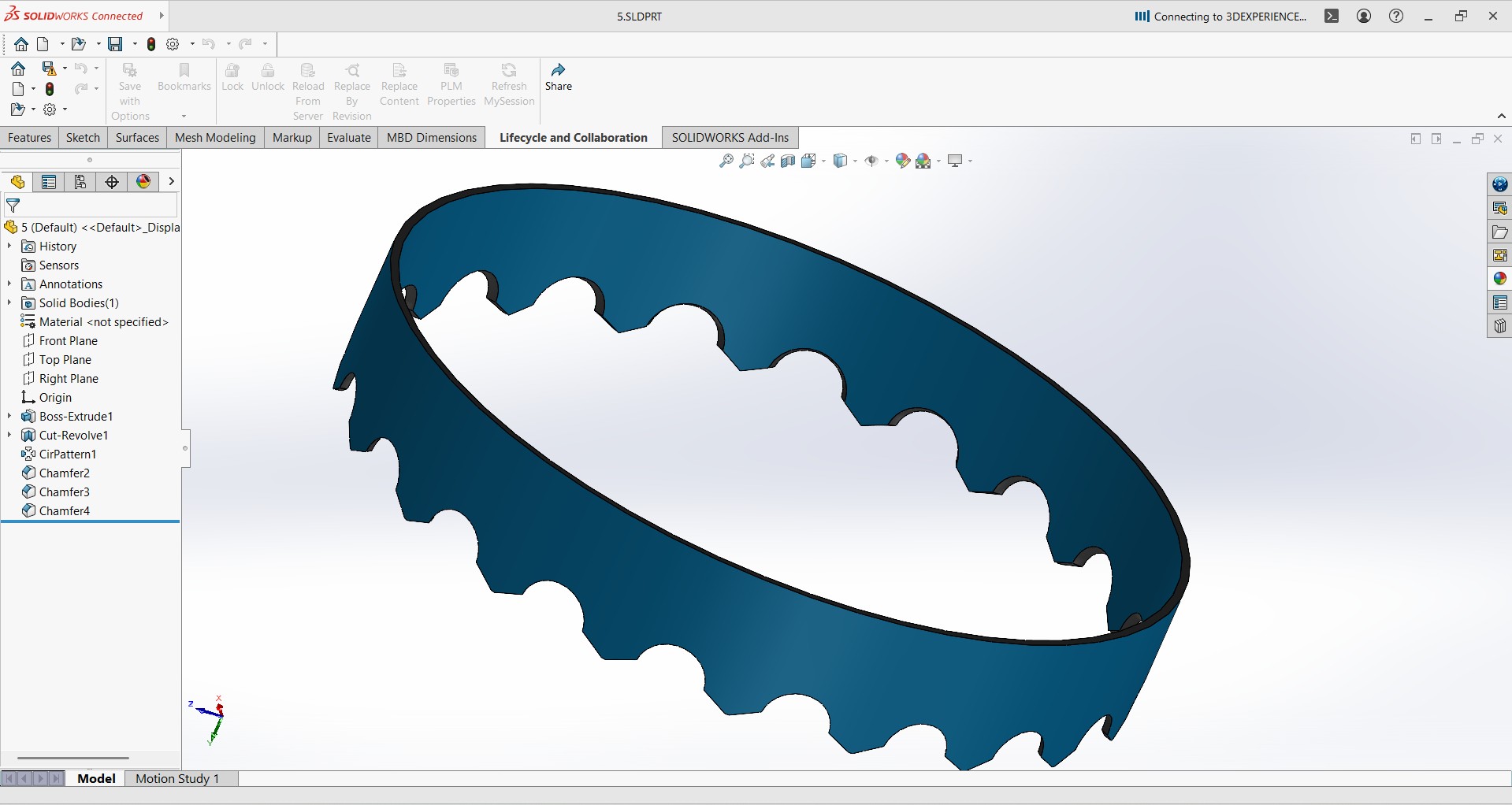
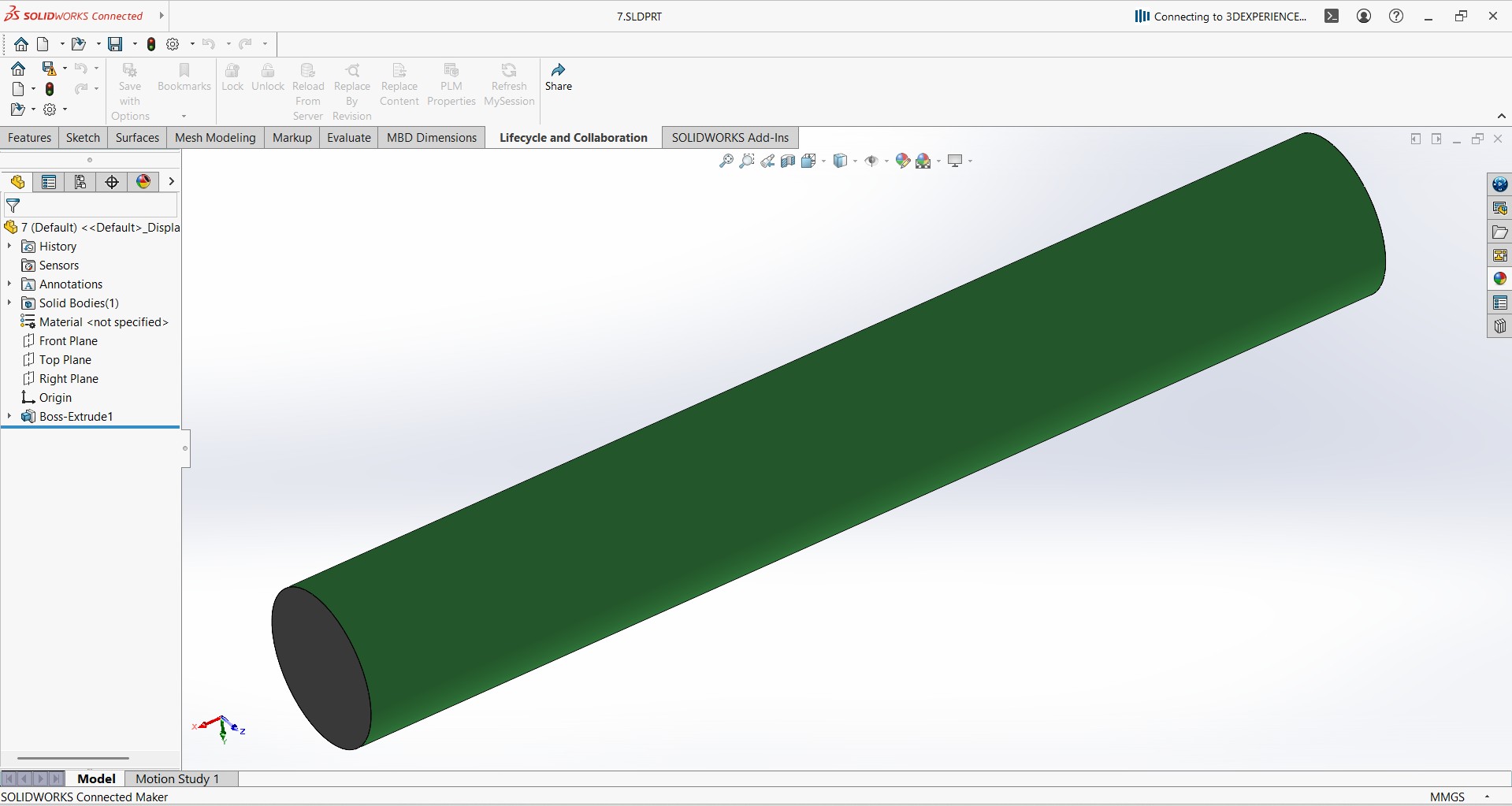
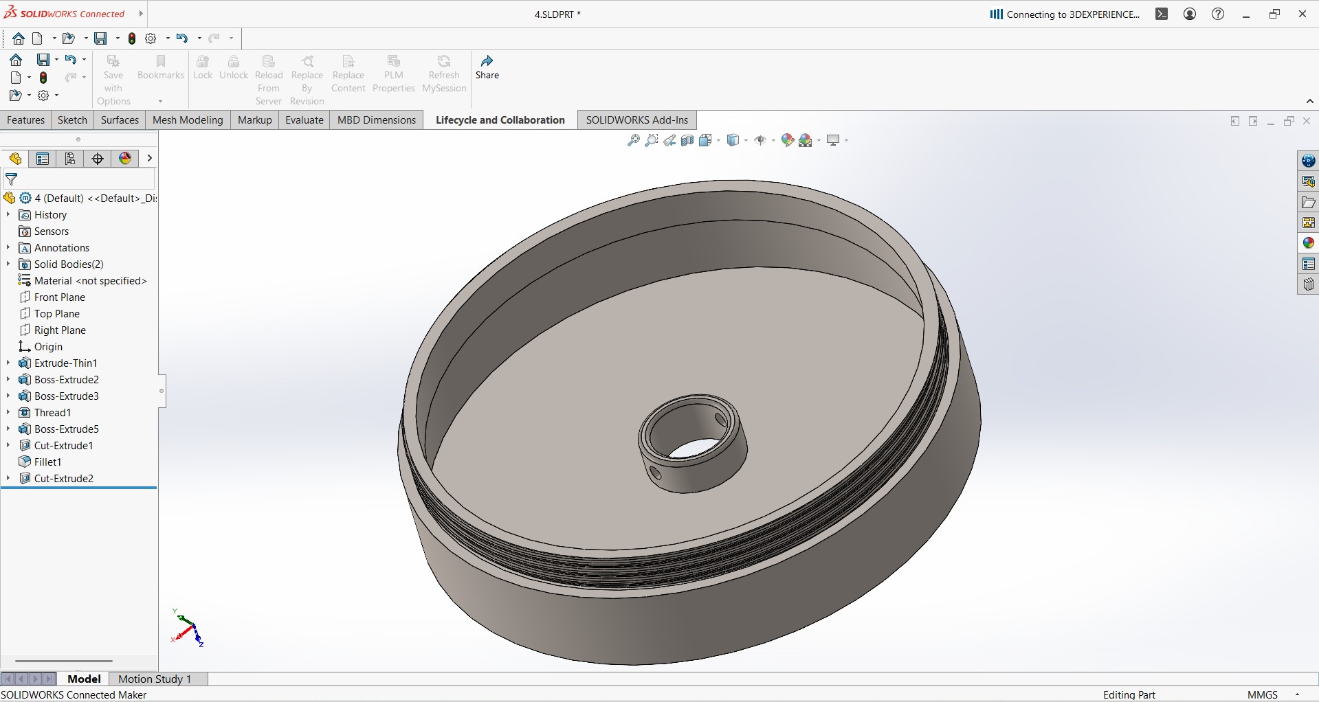
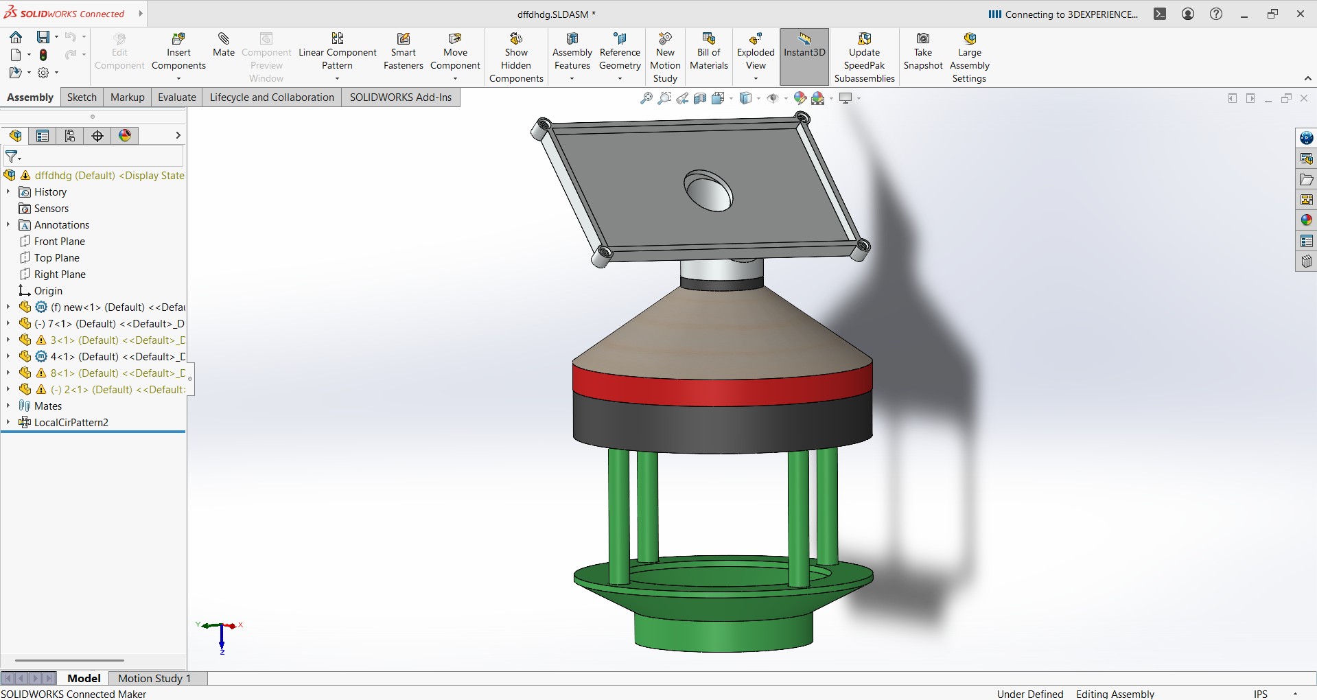
In the final stage of my project, I focused on designing the product with a clear vision. I carefully considered the manufacturing process and decided that most of the components should be 3D printed to ensure precision and ease of assembly. Some parts, however, were better suited for laser cutting due to their flat profiles, while others required the durability and strength provided by wood routing. Based on these considerations, I began designing the product accordingly.
My goal was to create a compact and cost-effective solution that could be mounted on a light pole or any standard vertical support structure. I aimed for a design that would be lightweight and aesthetically minimal, making it easy to install in polyhouses, farms, or any outdoor environment without requiring complex infrastructure.
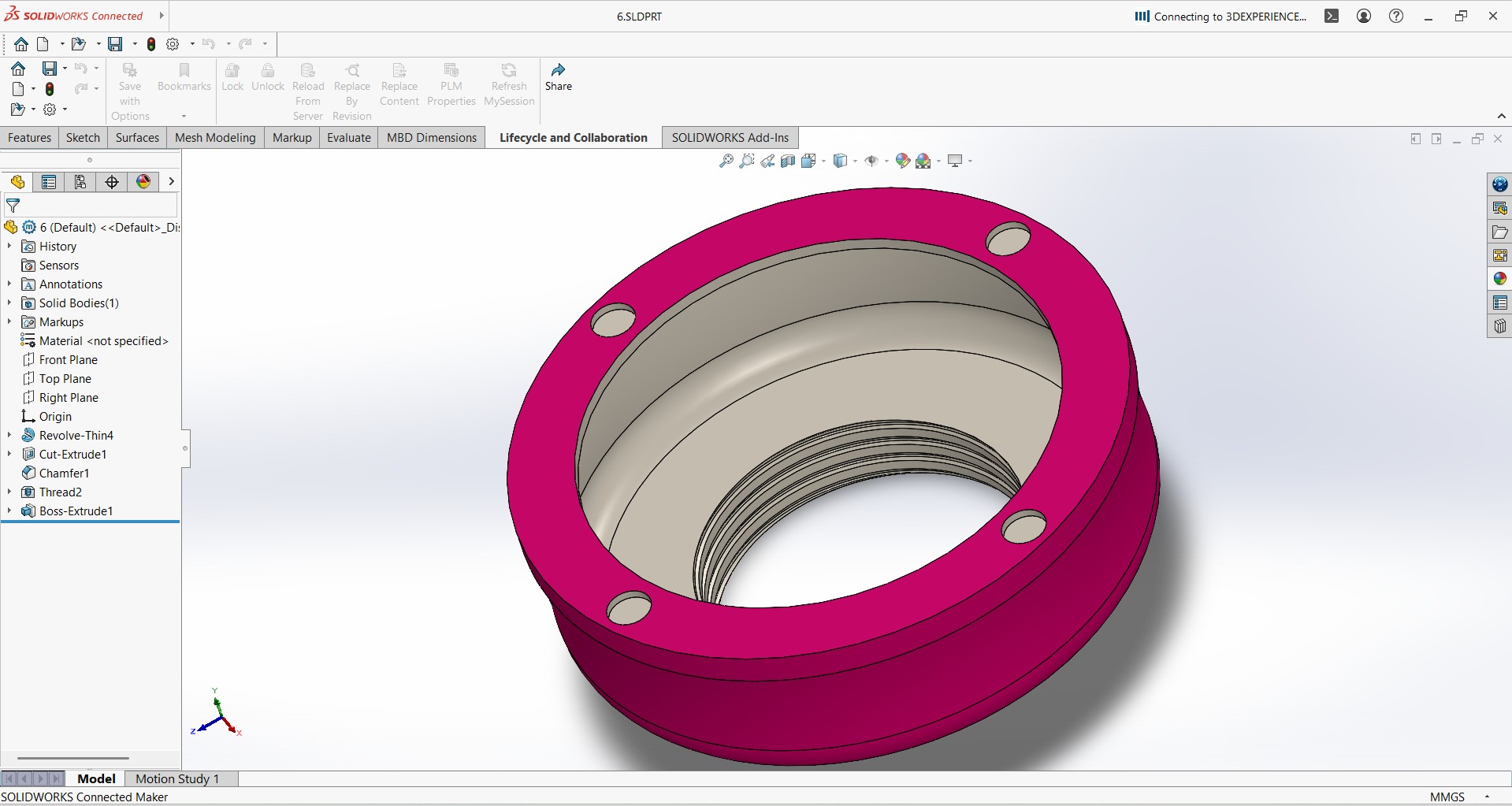
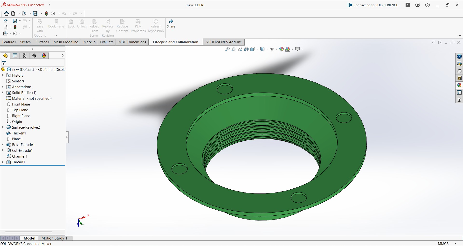
I designed all these components using SolidWorks, ensuring each part was accurately modeled according to the functional and manufacturing requirements of the final product.
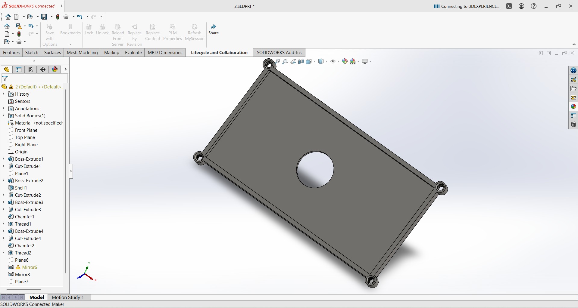
User-Centric Product Design with SolidWorks
I chose SolidWorks for creating the 3D design of my product. While designing in SolidWorks, I focused on making the product user-friendly, especially for rural communities. I ensured that each part of the product is easy to assemble and install by local users without requiring specialized skills. I also considered mobility and ease of handling and ensured that it can be serviced conveniently. Furthermore, I designed the product in such a way that users can rely on it with confidence. Each layer and component of the product was thoughtfully designed to ensure practical usability, durability, and local adaptability.
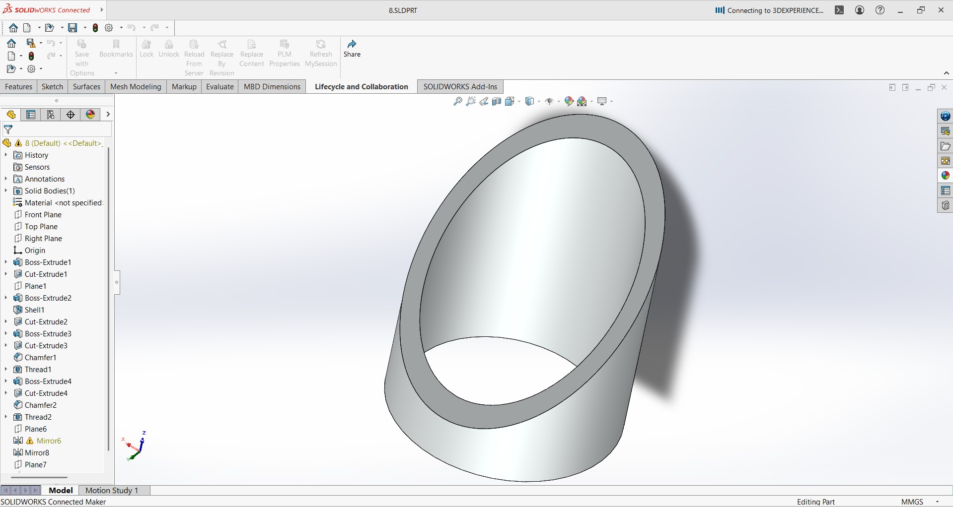
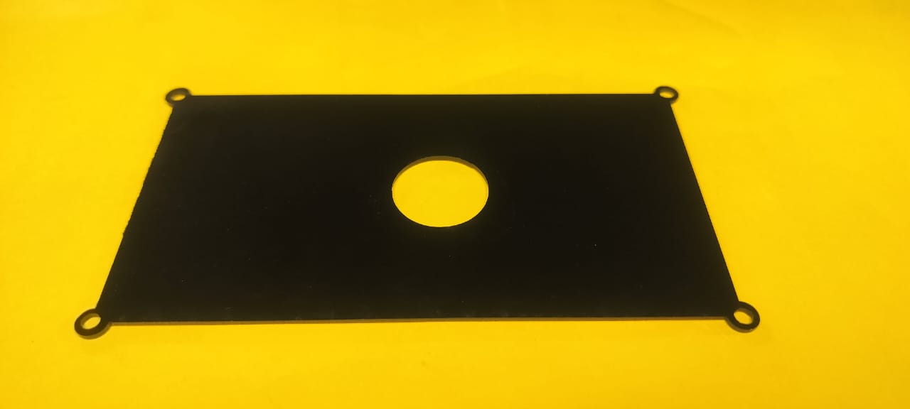
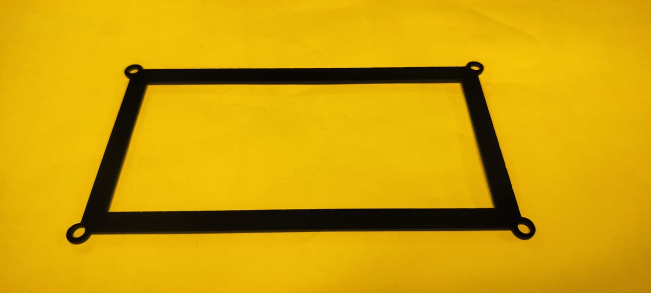
Fabrication Process: 3D Printing and Laser Cutting
To begin with, I performed the laser cutting process by precisely preparing the design and executing the cut on the selected material, ensuring accuracy and clean edges.
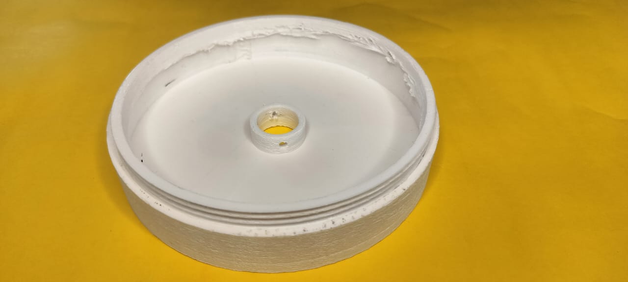
Assembling the Product
Once all the 2D and 3D components were fully designed, fabricated, and finalized, I proceeded with the assembly process. This stage involved carefully organizing each part and methodically putting them together according to the planned design structure. Special attention was given to alignment, fitting accuracy, and overall stability to ensure the product was assembled efficiently and functioned as intended.
Assembly & Testing Videos
|
Assembly of the electronic part
|
Assembly of the electronic part
|
|
Assembly the part
|
Final Testing
|
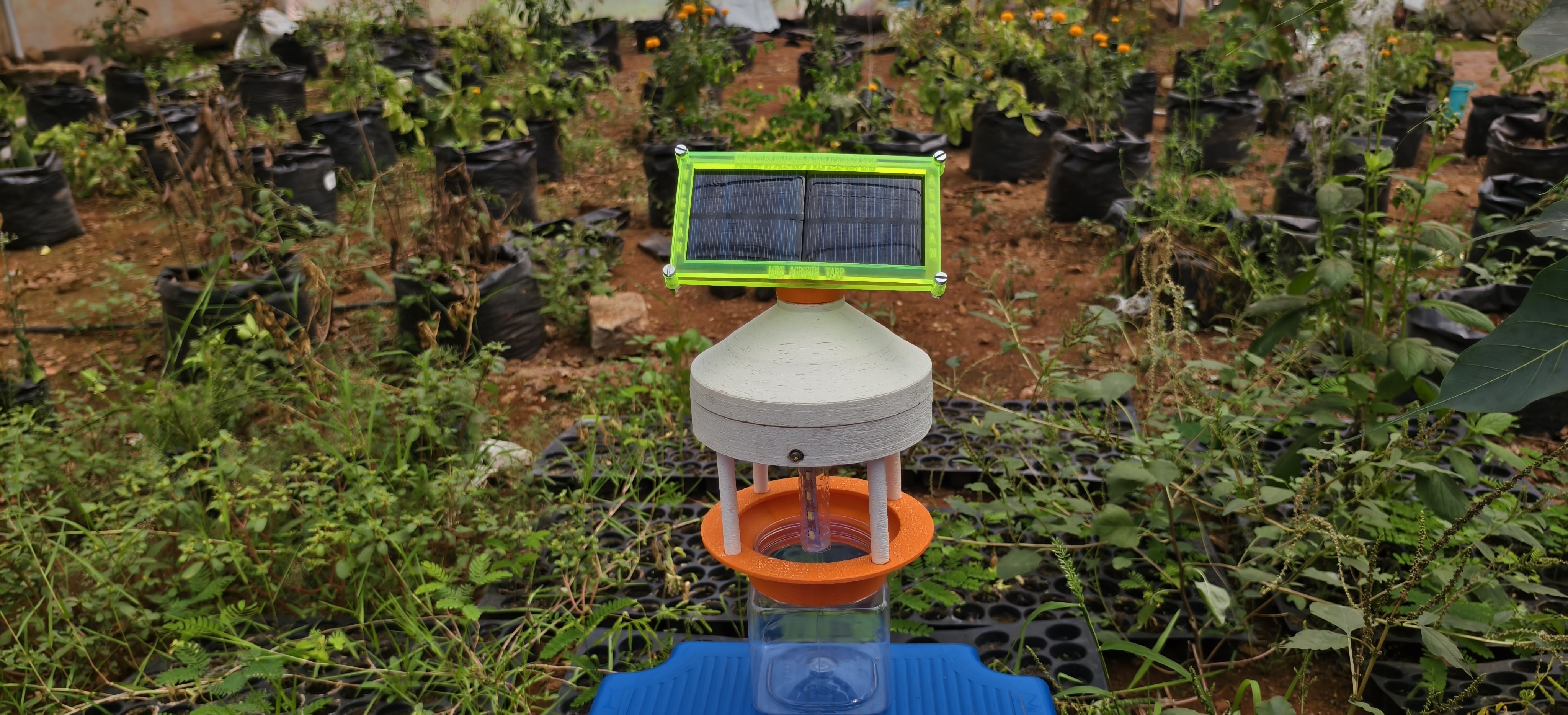
Final Product
My final product is ready for field testing.
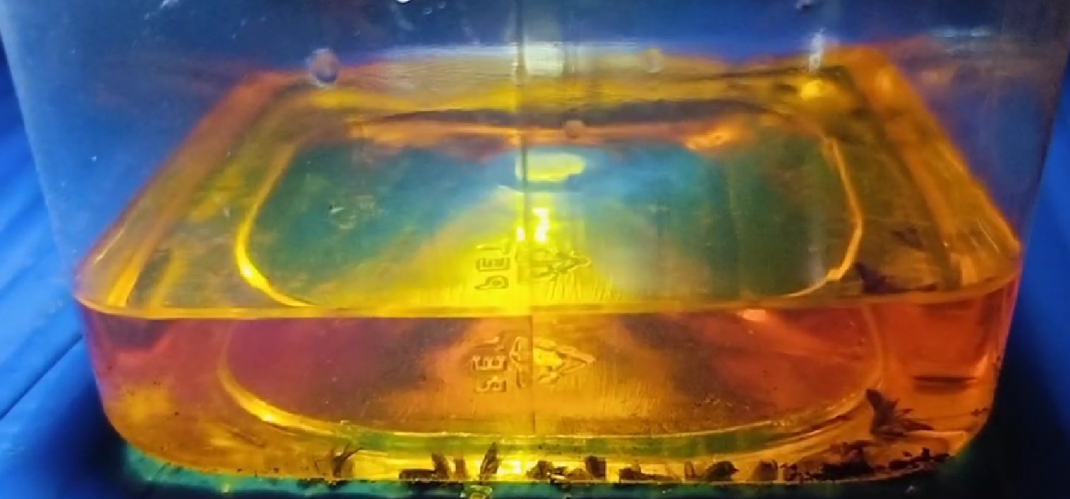
Field testing
For field testing, I installed my product inside a polyhouse, where there were dense trees and plants. As a result, the number of mosquitoes was quite high. I placed the product there in the evening, and as soon as it got dark, the LED of my product turned on. Gradually, mosquitoes started coming near it and buzzing around. After a while, I poured petrol into the jar. Due to the petrol, the mosquitoes flying near the trap fell into the jar and died. On monitoring the setup, I observed this result. There is still scope for improvement.
Integration of Fab Academy Assignments in Mini AgriSun Trap Development
| Assignment Name |
How It Was Used in My Final Project |
| 1. Principles and Practices / Project Management |
- Selected and planned the final project idea
- Created a timeline using Gantt chart
- Managed documentation through GitLab and website
|
| 2. Computer-Aided Design (CAD) |
- Designed 3D models using SolidWorks and FreeCAD
- Created the project logo in Fusion 360
- Edited images using GIMP and Inkscape
|
| 3. Computer-Controlled Cutting |
- Used laser cutter to make casing and mounting plates
- Achieved precise and clean parts for the structure
|
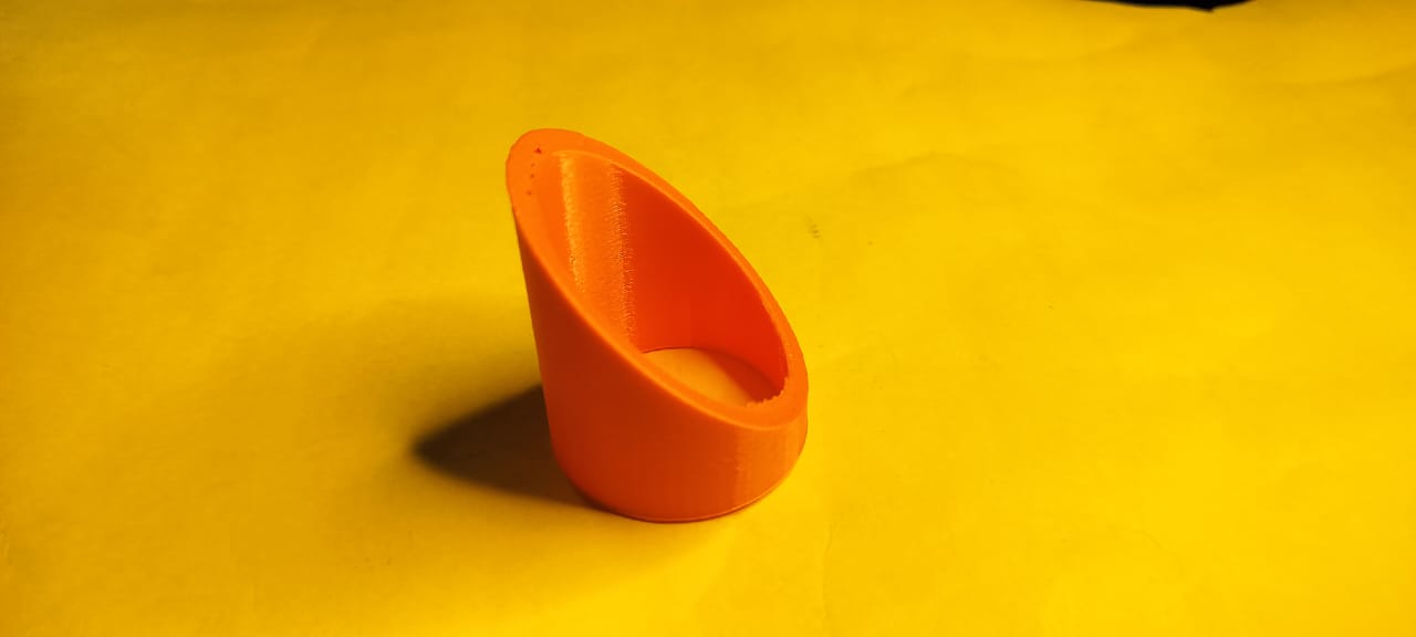
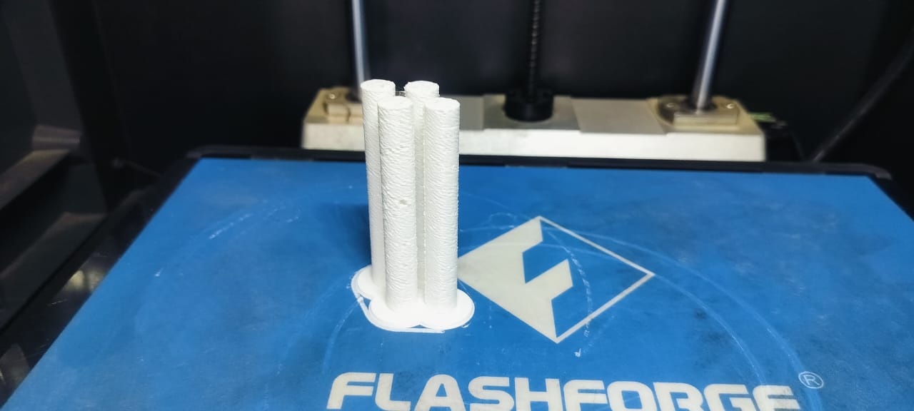
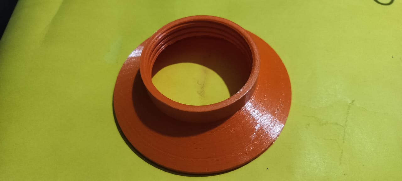
| 4. 3D Scanning and Printing |
- Printed casing components like top cover and entry tube using a 3D printer
- Generated G-code using FlashPrint 5
|
| 5. Electronics Design |
- Designed custom PCB using KiCad
- Included ATtiny1614, phototransistor sensor, LED, and battery connections
|
| 6. Electronics Production |
- Milled and soldered PCB using lab machines
- Assembled and tested all electronic components
|
| 7. Embedded Programming |
- Programmed ATtiny1614 to read sensor data and control LED
- Implemented power-saving features for solar usage
|
| 8. Input Devices |
- Used phototransistor to detect light levels
- Enabled system to work automatically based on day-night sensing
|
| 9. Output Devices |
- Connected a UV LED strip to attract insects at night
- Controlled output based on sensor input
|
| 10. Project Development |
- Integrated all parts: 3D printed body, PCB, wiring, and solar panel
- Conducted testing and finalized documentation, photos, and videos
|
| 11. Applications and Implications |
- Designed a solar-powered, chemical-free insect trap for farmers
- Helps reduce pesticide use and supports sustainable agriculture
|
System Integration
As part of the final project development, I completed the system integration assignment.
You can view the full documentation here.
- Integrated 3D printed casing, PCB electronics, solar power system, and embedded programming into a complete working system.
- Designed all hardware components and established physical connections between them.
- Created PCB design in KiCad, connecting ATtiny1614 microcontroller with phototransistor sensor and LED.
- Fitted all electronic parts into the 3D printed casing to make the system sturdy and portable.
- Ensured continuous power supply by connecting solar panel and battery.
- Developed embedded code to read sensor inputs and control the LED output accordingly.
- Tested the entire system thoroughly to confirm smooth coordination between all components.
- Faced challenges during 3D printing as some parts did not print perfectly; overcame these through multiple trials and adjustments.
- Calibrated the sensor after repeated testing to achieve accurate results.
- Uploaded photos, code, design files, and testing videos of every step on GitLab for proper documentation.
- Documented the complete project process and detailed explanation on the project website for easy understanding by others.
Credits
I express my heartfelt gratitude to the following individuals from Vigyan Ashram, whose guidance, support, and collaboration were instrumental in the successful completion of my final project:

Subhash Labade
For sharing the initial concept and inspiring the foundation of this project.

Dipali Kamble
For motivating and guiding the project from its early stages.

Pranit Kamble
For identifying technical challenges and helping resolve the polyhouse drying issue.

Chadwik
For his expert help in 3D designing and visualization.
Umesh Imphal
For actively supporting the field testing and validation of the system.
Aarti Bhosale
For assisting in component assembly and ensuring smooth integration.

Parnit Sankpal
For technical support in coding and programming aspects of the project.

Shivraj Singh
For providing continuous mentoring and valuable feedback throughout development.
📁 Original Files
🛠 Tools I Used
⚙️ Fabrication Tools