Electronics Production
Learning Experience
During this week, my primary focus was on designing, fabricating, and assembling a custom microcontroller development board to gain a deeper understanding of the electronics production process. I utilized the MonoFab SRM-20 milling machine to precisely mill the PCB, converting Gerber files into G-code using the Mods software platform. Furthermore, I delved into surface preparation methods, carefully selected suitable cutting tools, and operated the CNC machine using V-Panel to ensure accurate and high-quality PCB output. This hands-on experience significantly enhanced my skills in electronics design and manufacturing.
Key Accomplishments
✅The XIAO ESP32-C3 was used to design a microcontroller development board.
✅Mods were used to generate Gerber files and convert them to G-code.
✅ Used the SRM-20 to mill a PCB with accurate cuts and traces.
✅ Managed toolpaths and set origins while operating the V-Panel CNC milling program.
✅ The PCB was cleaned and prepared to guarantee a solderable surface.
✅ Acknowledged the significance of feeds, speeds, and bit selection in PCB manufacture.
Task: Electronics Production
Group assignment:
Characterize the design rules for your in-house PCB production process: document feeds, speeds, plunge rate, depth of cut (traces and outline) and tooling.
Document the workflow for sending a PCB to a boardhouse
Document your work to the group work page and reflect on your individual page what you learned
Individual assignment:
Make and test a microcontroller development board that you designed
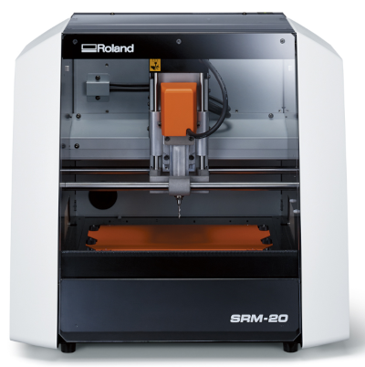
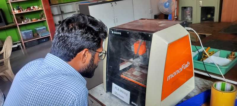
MonoFab SRM-20
As a small milling machine, the SRM-20 offers compact size and powerful functionality at an affordable price. Production of realistic parts and prototypes is made simple and convenient with a device that fits into any office, studio, or classroom environment. For users looking for advanced milling capabilities without the need for expert operating skills, the SRM-20 is one of the easiest and most precise CNC mills in its class.
Specifications
| Model |
SRM-20 |
| Cuttable Material |
Modelling Wax, Chemical Wood, Foam, Acrylic, Poly acetate, ABS, PC board |
| X, Y, and Z Operation Strokes |
203.2 (X) x 152.4 (Y) x 60.5 (Z) mm |
| Workpiece table size |
232.2 (X) x 156.6 (Y) mm |
| Distance From Collet Tip to Table |
Max, 130.75mm (5.15 in) |
| Loadable Workpiece Weight |
2 kg (4.4 lb) |
| X-, Y-, and Z-Axis Drive System |
Stepping motor |
| Operating Speed |
6 - 1800mm/min (0.24 - 70.87 inch/min) |
| Software Resolution |
0.01 mm/step (RML-1), 0.001mm/step (NC code) |
| Mechanical Resolution |
0.000998594 mm/step (0.0000393 inches/step) |
| Spindle Motor |
DC motor Type 380 |
| Spindle Rotation Speed |
Adjustable 3000 - 7000 rpm |
| Cutting Tool Chuck |
Collet method |
| Interface |
USB |
| Control Command Sets |
RML-1, NC code |
| Power Requirements |
Machine: DC24V, 2.5A, Dedicated AC adapter: AC 100-240 V ±10%, 50/60 Hz |
| Power Consumption |
Approx. 50 W |
| Operating Noise |
During operation: 65 dB (A) or less (when not cutting), During standby: 45 dB (A) or less |
| External Dimensions |
451.0 (W) x 426.6 (D) x 426.2 (H) mm |
| Weight |
19.6 kg (43.2 lb) |
| Installation Environment |
Temperature of 5 to 40°C (41 to 104 °F), 35 to 80% relative humidity (no condensation) |
| Included Items |
USB cable, AC adapter, Power cable, Cutting tool, Collet, Set screw, Spanners (7,10mm), Hexagonal wrench (size 2,3 mm), Positioning pins, Double-sided tape, Start-up page guidance card |
monoFab SRM-20 Accessories
| Category |
Item |
Model |
Description |
| End-mills |
Square end-mills |
ZHS-100 |
High speed steel dia. 1 3(l)×6(d)×50(L)×2NT |
| Square end-mills |
ZHS-200 |
High speed steel dia. 2 6(l)×6(d)×50(L)×2NT |
| Square end-mills |
ZHS-300 |
High speed steel dia. 3 10(l)×6(d)×50(L)×2NT |
| Square end-mills |
ZHS-400 |
High speed steel dia. 4 12(l)×6(d)×50(L)×2NT |
| Square end-mills |
ZHS-500 |
High speed steel dia. 5 15(l)×6(d)×55(L)x2NT |
| Square end-mills |
ZHS-600 |
High speed steel dia. 6 15(l)×6(d)×55(L)x2NT |
| Square end-mills |
ZHS-3015 |
High speed steel dia. 3 15(l)x6(d)x50(L)x2NT; 2 piece |
| Ball end-mills |
ZCB-150 |
Cemented Carbide R1.5 25(l)×2.4(Lc)×65(L)×6(d)×2NT |
| Ball end-mills |
ZCB-200 |
Cemented Carbide R2 25(l)×3.2(Lc)×70(L)×6(d)×2NT |
| ZCB-300 |
Cemented Carbide R3 30(l)×4.8(Lc)×80(L)×6(d)×2NT |
| Engraving cutter |
ZEC-100 |
Engraving cutters (for plastic) Cemented Carbide dia. 6×50 (L)×0.225 (W) |
| Collets |
ZC-20-30 |
Collet (for end-mills), dia. 3mm |
| ZC-20-32 |
Collet (for end-mills), dia. 3.175mm |
| ZC-20-40 |
Collet (for end-mills), dia. 4mm |
| ZC-20-60 |
Collet (for end-mills), dia. 6mm |
| Others |
SM-20 |
Replacement spindle motor |
| SS-20 |
Replacement spindle unit |
Reference Website Mono FAB
Equipment Used in Operating the SRM-20 Milling Machine

1. 1/64 Inch End Mill: This is a small-diameter tool specifically designed for precise engraving, detailed cuts, and creating isolation traces or fine trenches on a PCB during the milling process.

2. 1/32 Inch End Mill: Slightly larger than the 1/64 end mill, this bit is ideal for general engraving, precision milling, and for cutting along the edges or shaping the outline of a PCB board.

3. V Bit: A V-shaped cutting tool commonly used for engraving, chamfering, and producing sharp, clean edges on various materials.
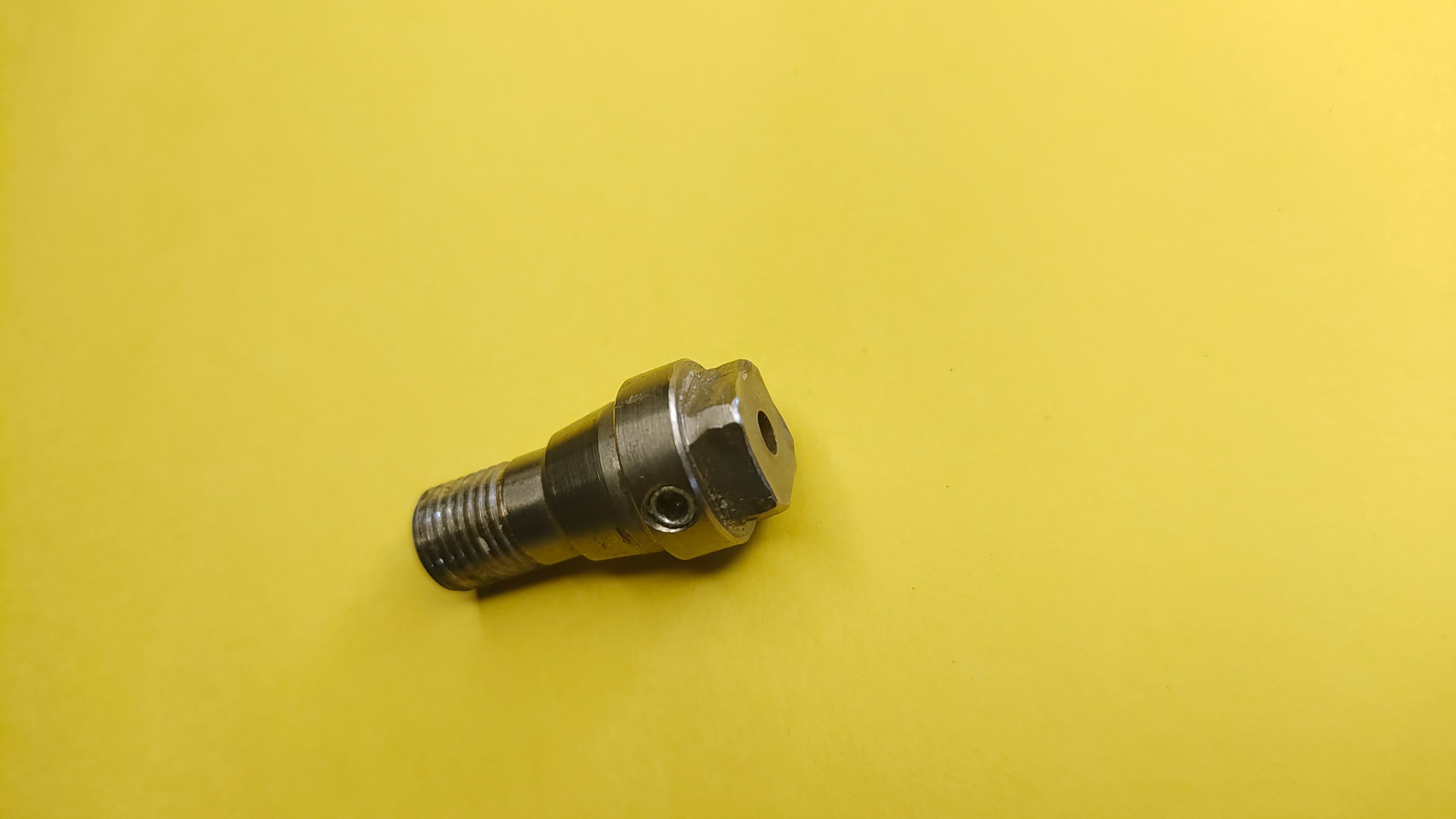
4. Collet: A cylindrical clamping device that securely holds the end mill in place within the spindle of the milling machine, ensuring accurate operation.
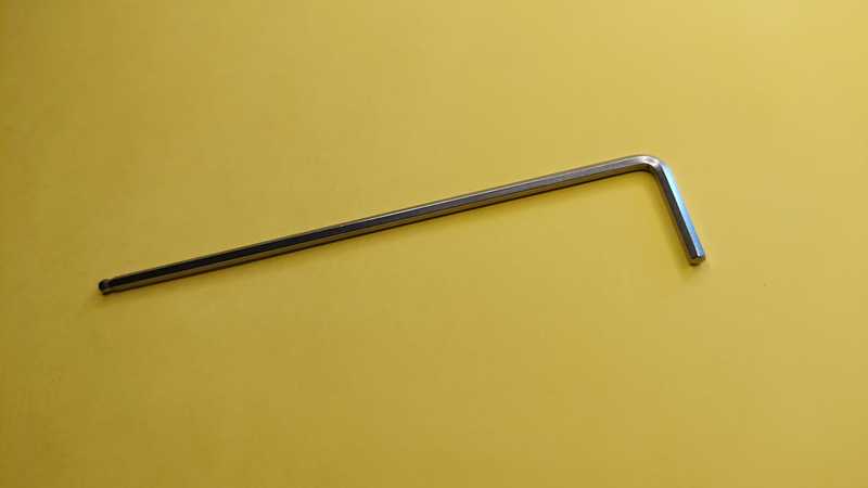
5. Allen Key (LNKEY): A handheld tool used for tightening or loosening screws and bolts on tool holders or CNC machine components, aiding in tool installation and adjustment.
6. FR1 (PCB Material): A flame-retardant material widely used in the fabrication of printed circuit boards (PCBs), offering a stable base for circuit design and milling operations.
Electronics Production
The process of electronics production involves transforming design concepts into fully functional electronic devices. This comprehensive procedure includes several key stages such as circuit design, sourcing electronic components, assembling the hardware, conducting performance tests, fabricating enclosures, implementing quality control measures, and finally, packaging the finished product for delivery.
Electronics Designing Process
For my electronic design, I have selected the XIAO ESP32-C3 board due to its built-in Wi-Fi and Bluetooth capabilities, which are critical for the wireless communication needs of my project. This board also supports easy integration with various sensors and a display unit, making it a highly efficient and compact choice for my embedded system design.
Components Used for the PCB Device
The following surface-mount components were used to complete the custom PCB design:
- 3 SMD Resistors (1001, 1001, 4990 values)
- 1 SMD Green LED
- 1 SMD Omron 5-pin Switch
- 3 SMD Three-pin Connectors
- 1 SMD Four-pin Connector
- 1 XIAO ESP32-C3 Development Board
By utilizing the XIAO ESP32-C3 module, this PCB enables robust wireless connectivity via Wi-Fi and Bluetooth. It is well-suited for applications in smart systems such as IoT devices, automation solutions, and real-time data monitoring platforms. The board's compact size and efficient performance contribute significantly to the overall reliability and scalability of the project.
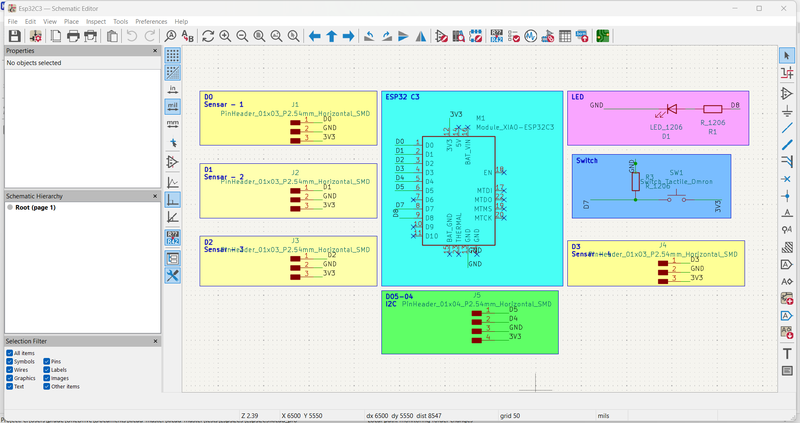
Schematic design of the PCB circuit
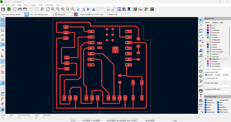
PCB layout with routed tracks. I also downloaded the Gerber files for fabrication.
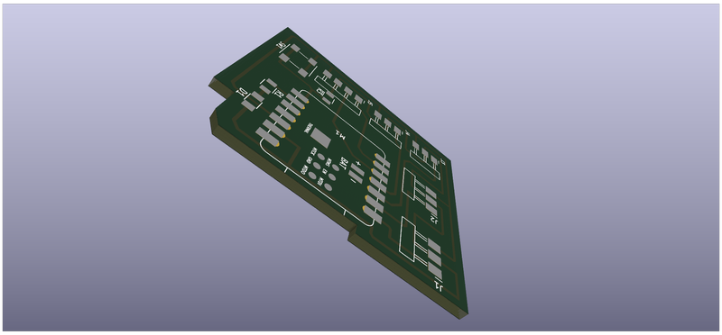
3D visualization of the PCB using KiCad's viewer
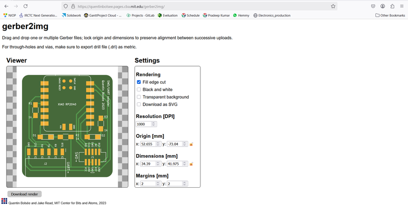
I used the Gerber2Image tool, as recommended during our Fab Academy session, to convert the Gerber files into PNG format by simply dragging and dropping the files into the tool.
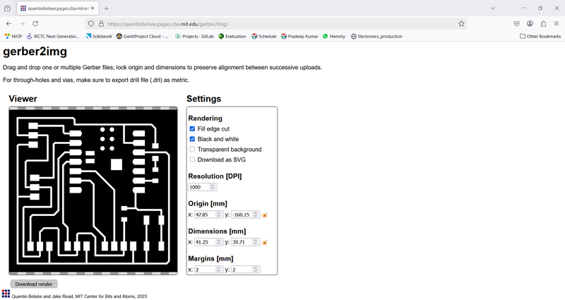
Downloaded PNG image of the inner PCB layer
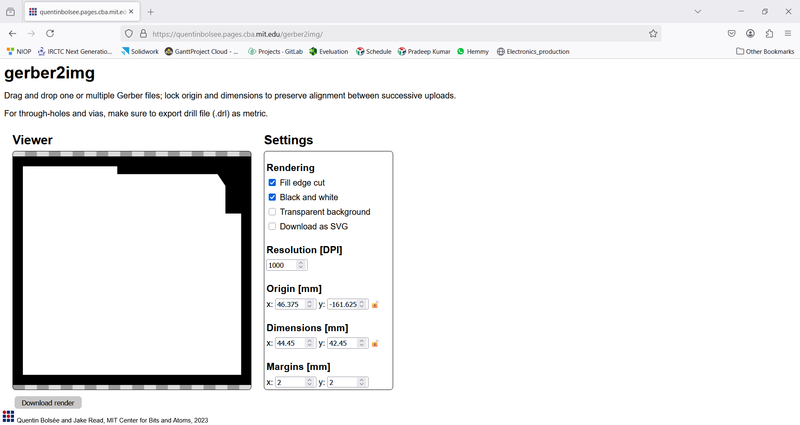
Downloaded PNG image of the outer PCB layer
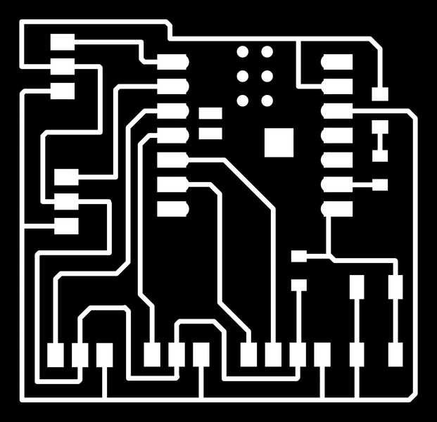
Rendered image showing the inner PCB design

Rendered image showing the outer PCB design
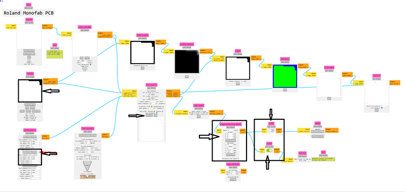
Using Mods for G-Code Generation
What are Mods?
Mods is an open-source, browser-based, node-oriented visual programming platform designed specifically for digital fabrication workflows. Instead of manually writing complex G-code, users can generate machine instructions through an intuitive drag-and-drop interface, making the fabrication process more accessible and efficient.
Key Features of Mods:
- Web-Based Interface: Runs directly in your browser with no installation required.
- Modular Workflow: Users can create customized workflows by connecting modular blocks called "nodes."
- Multi-Machine Support: Compatible with various digital fabrication machines including ShopBot, Roland, and others.
- Real-Time Response: Automatically updates toolpaths based on real-time user inputs.
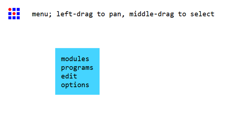
I started by navigating to https://modsproject.org/. Upon loading, the homepage redirected me to the dashboard interface.
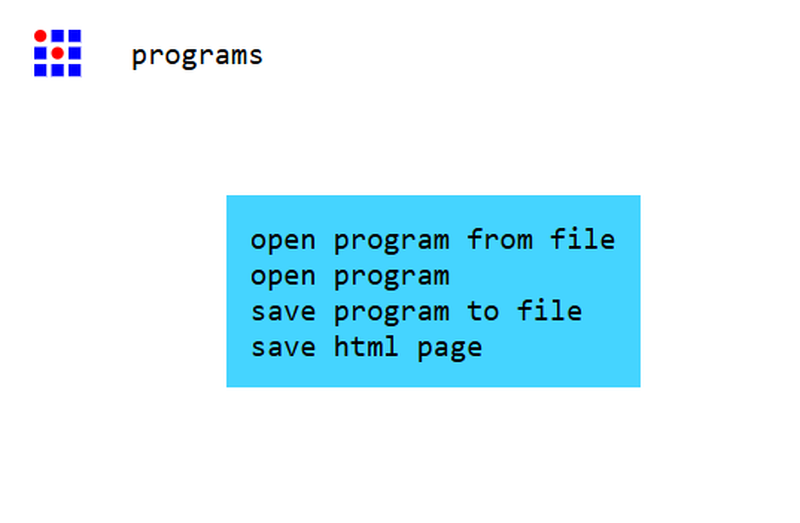
From the dashboard, I proceeded to open the appropriate program for PCB milling.
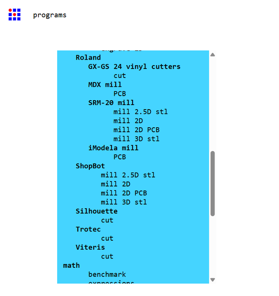
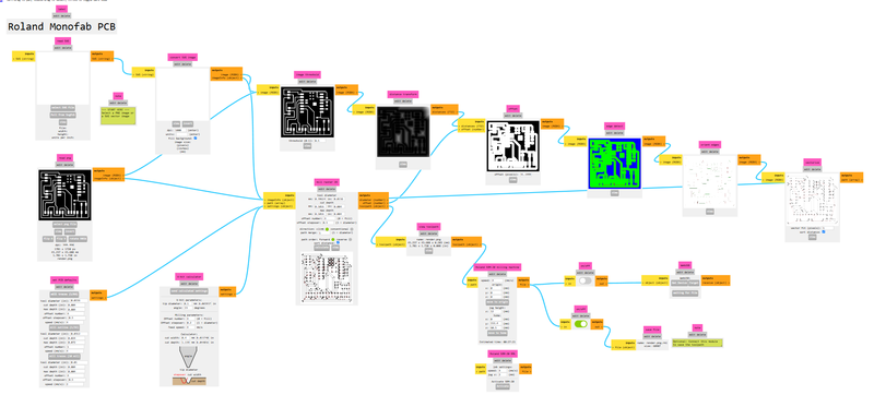
I selected the "Mill 2D PCB" workflow, which is designed for generating G-code for two-dimensional PCB milling operations.
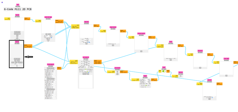
The dashboard remains visible throughout the process, allowing easy access to different modules and parameters.
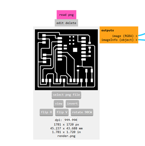
I then uploaded the PNG image of the PCB layout that I wanted to mill.
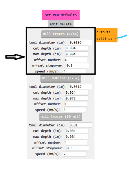
For the milling process, I chose a 1/64-inch end mill to ensure fine detail in the traces.
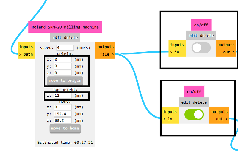
I configured the settings by disabling the top button, enabling the bottom one to prepare for saving the G-code, and set the XYZ origin to 0-0-0. The jog height was adjusted to 12 mm for safe movement of the tool head.
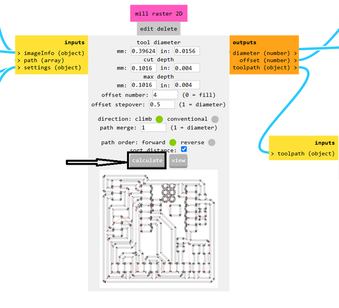
After verifying all settings, I clicked the "Calculate" button. Once the calculation completed, the G-code was successfully generated.
This image shows the internal routing of the PCB during the processing phase.
This image displays the external routing path that defines the board's outline.
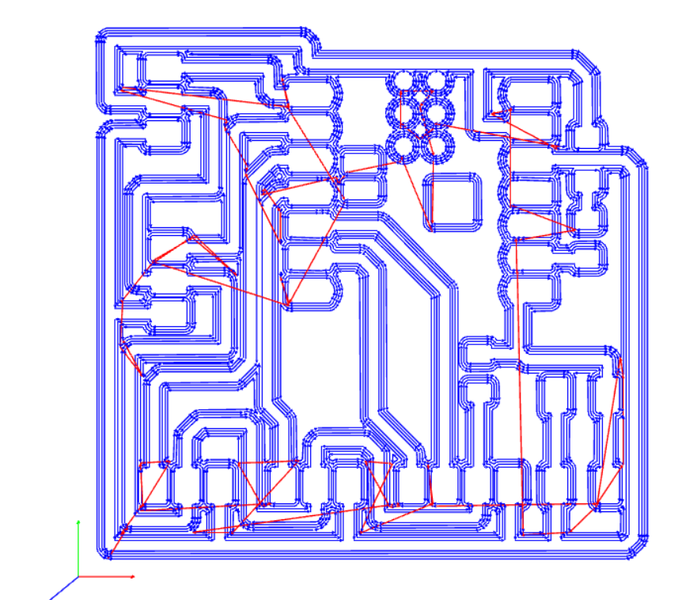
Here is a preview of the toolpath generated using the 1/64-inch milling bit, optimized for detailed circuit traces.
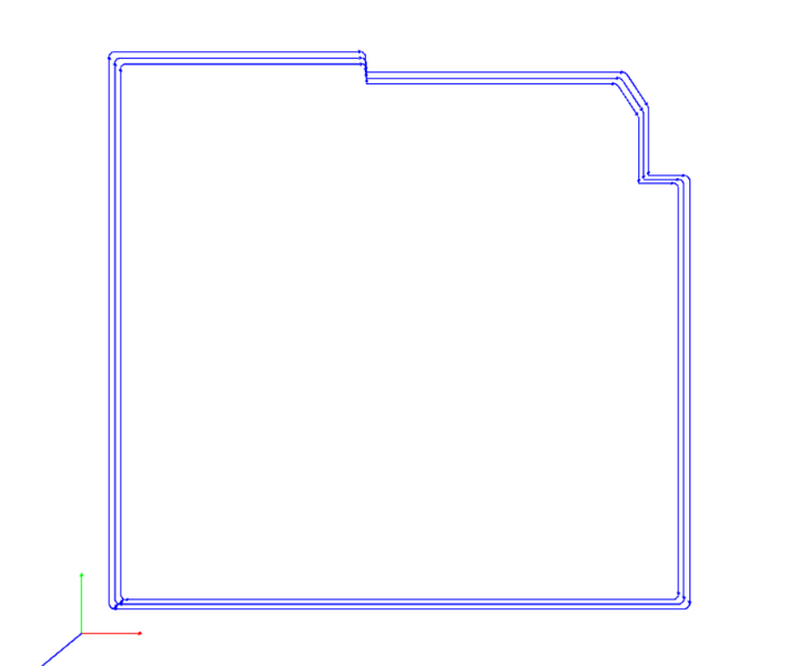
This is the toolpath preview for a 1/32-inch bit, typically used for cutting the PCB's outer contour.
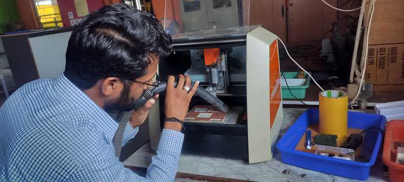
Operating the V-Panel for PCB Cutting and Milling
The Roland SRM-20 and similar CNC milling machines are operated using V-Panel software. This application provides a user-friendly interface that allows precise control over machine parameters such as spindle speed, origin settings, and milling commands. It simplifies the overall process of PCB fabrication, making it accessible even to beginners.
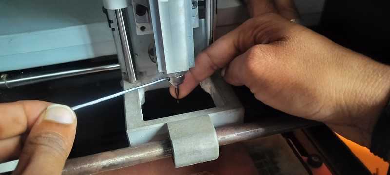
I began by installing the 1/64 inch milling bit into the spindle of the machine.
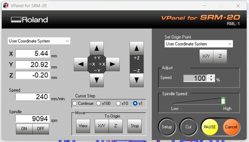
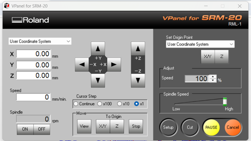
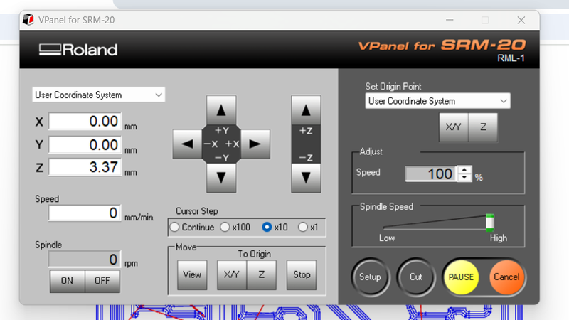
Next, I launched the V-Panel software and carefully moved the milling bit to the starting origin on the PCB surface.
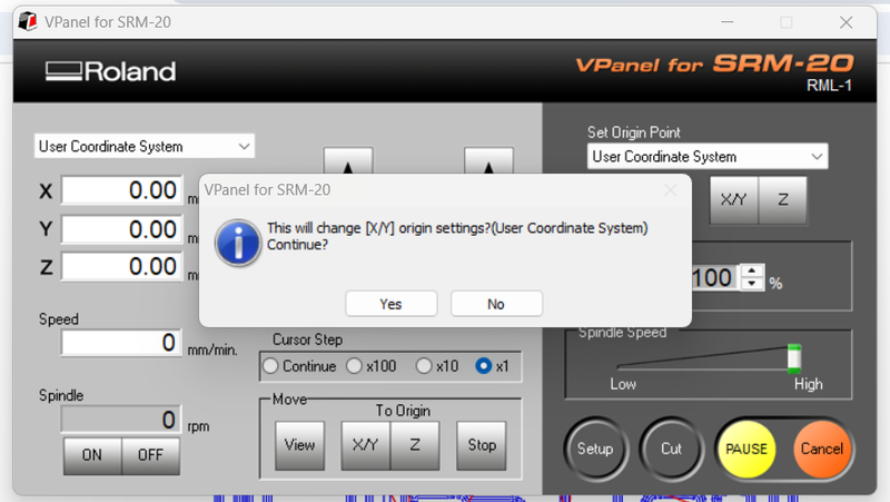
Then, I accurately set the XY-axis origin to ensure correct cutting depth.
After loosening the bit slightly, I allowed it to gently touch the PCB surface under gravity before tightening it again.
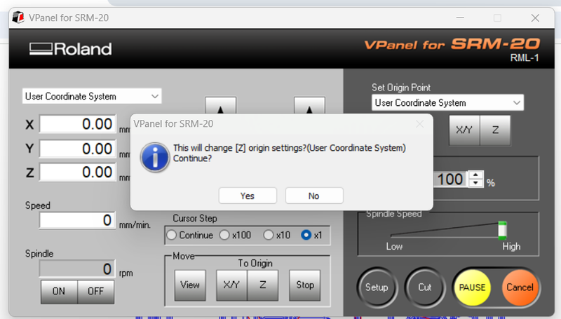
I reconfirmed the Z origin setting to match the new bit position.
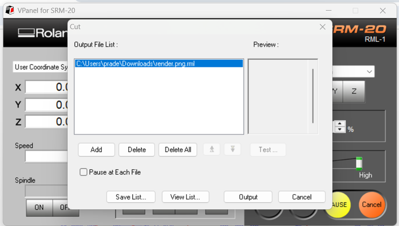
I selected the 'Cut' option from the V-Panel interface to begin preparing the file for milling.
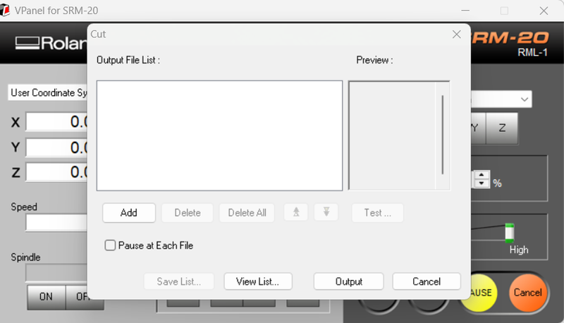
By clicking on the 'Add' button, I was able to upload the milling file to the software.
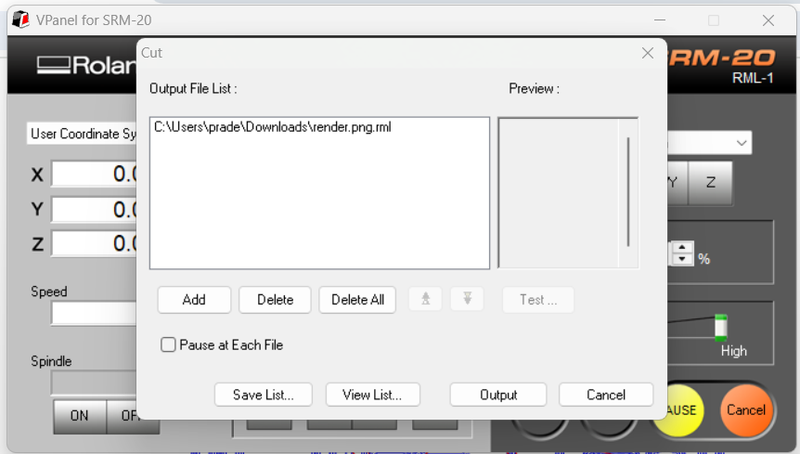
After choosing the appropriate trace file, I clicked on the 'Output' button to start the milling process.
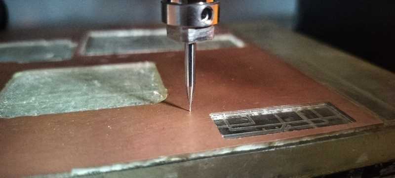
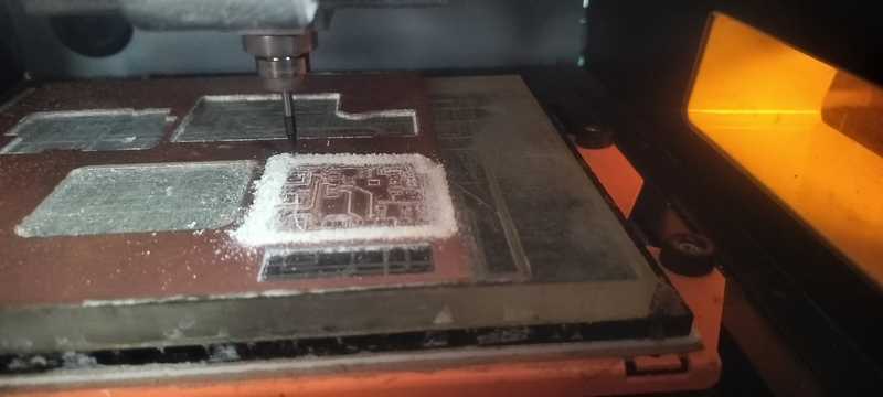
Once initiated, the machine began the milling operation automatically.
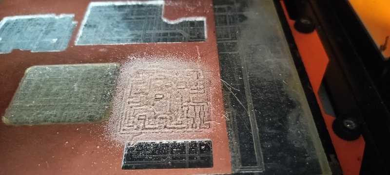
The trace pattern was successfully milled onto the PCB surface as per the design.
I cleaned the surface of the PCB using a vacuum cleaner to remove the milling dust and ensure clarity of the traces.
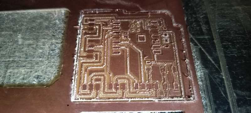
The traces appeared sharp and well-defined after the cleaning process.
Since a different bit was required for edge cutting, I raised the Z-axis to make the replacement.

I replaced the previous bit with a 1/32 inch bit for performing the edge cut operation.
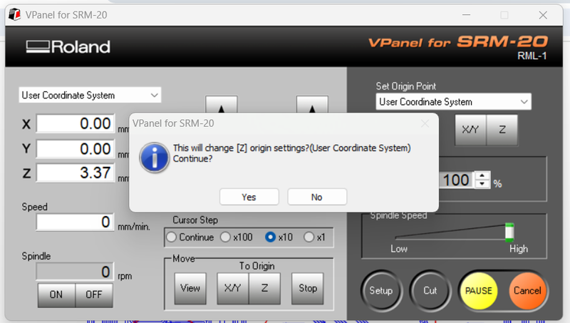
Only the Z origin was reset to match the length of the new bit.
After selecting the edge cut file, I clicked on 'Output' to begin the process.
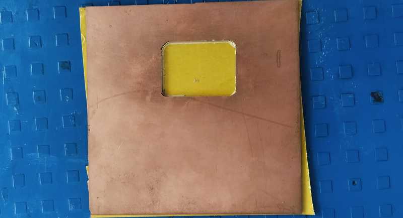
The edge cutting process completed successfully, separating the PCB from the substrate.
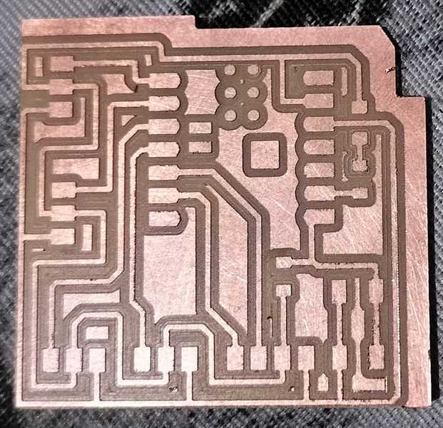
At this stage, the PCB was completely milled and ready for the soldering of components.
This comprehensive procedure outlines how I carefully mounted the milling bit, set the machine's origin points, milled the PCB traces, and performed the final edge cut. After cleaning the board, it was fully prepared for the next phase—soldering the electronic components.
Soldering Process
The soldering process is used to establish both electrical and mechanical connections between metal components. This is typically achieved by melting a low-melting-point alloy (solder), which is then applied to the metal parts that need to be joined. Once the solder cools and hardens, it forms a solid connection between the components.
To perform soldering effectively, specific tools are required. A professional-level setup includes a temperature-controlled soldering station with a fine-tipped iron, a hot air rework station, and ideally, a set of soldering tweezers. For precision work, a binocular microscope is also recommended for enhanced visibility.
Tools
- Temperature-Controlled Soldering Station
- Hot Air Rework Station
- SMD Tweezer and Soldering Iron
- Preheater Plate
- Microscope or Magnifier
- Solder Paste Dispenser
- Reflow Oven
- Vacuum Pickup Tool
- ESD Mat and Wrist Strap
- Fume Extractor
Components
- 3 Resistors (1001, 1001, 4990 SMD)
- 1 Green LED (SMD)
- 1 Omron 5-Pin Switch (SMD)
- 3 Three-Pin Connectors (SMD)
- 1 Four-Pin Connector (SMD)
- 1 XIAO ESP32-C3 IC
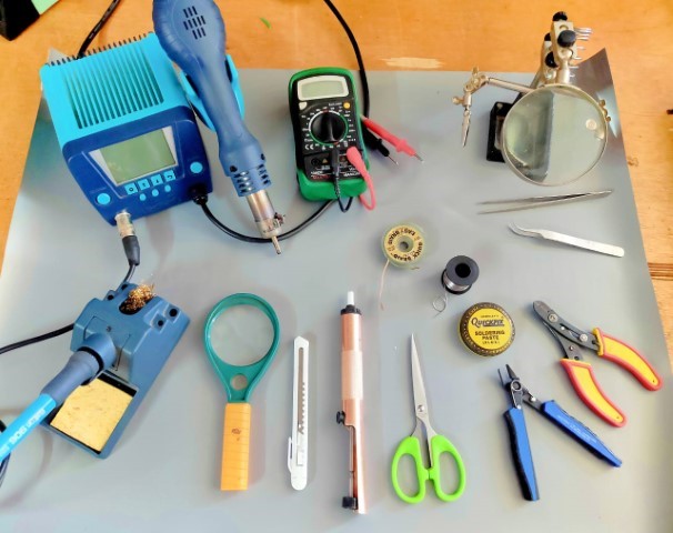
Tools used for the soldering station
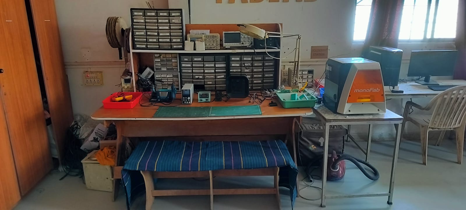
The soldering station setup
Blank PCB before soldering
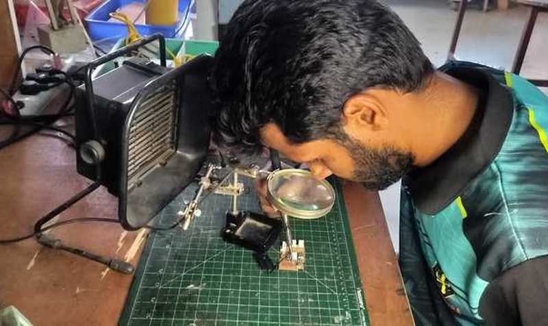
Starting the soldering process with guidance from Subhash Sir
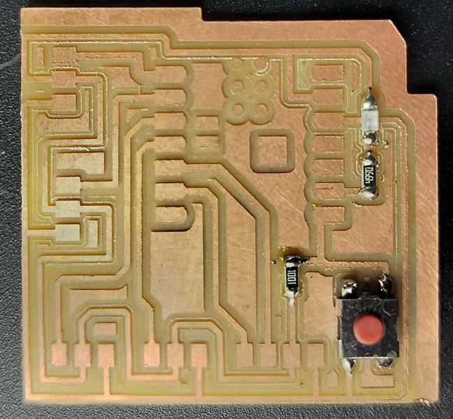
The first step was to solder the smaller components
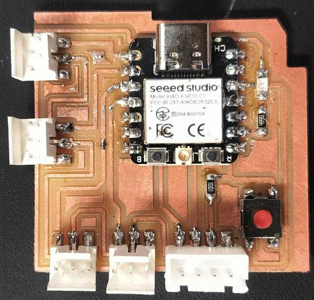
Next, I soldered the IC and connectors, completing the PCB which is now ready for programming
Testing the Microcontroller Board
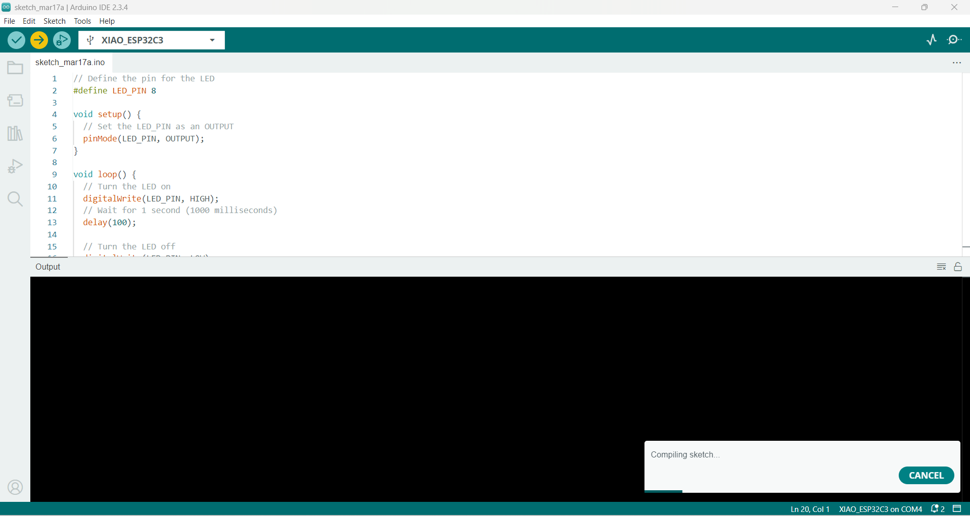
In order to program and test the custom microcontroller board I created, I used the Arduino IDE to ensure everything was functioning as expected.
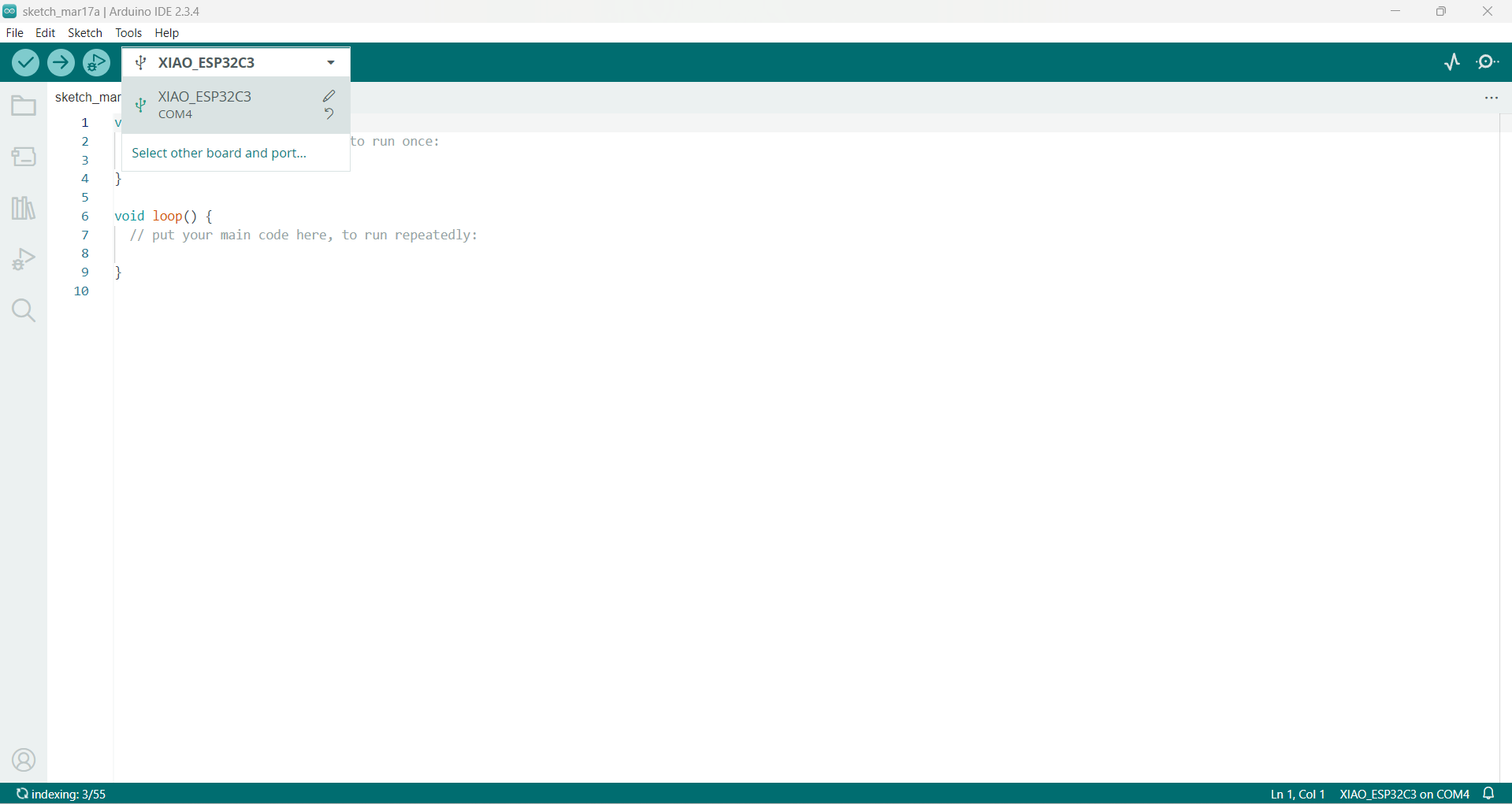
To begin, I launched the Arduino IDE and selected the XIAO ESP32C3 as the target board. I also set the port to COM4 for proper communication.
|
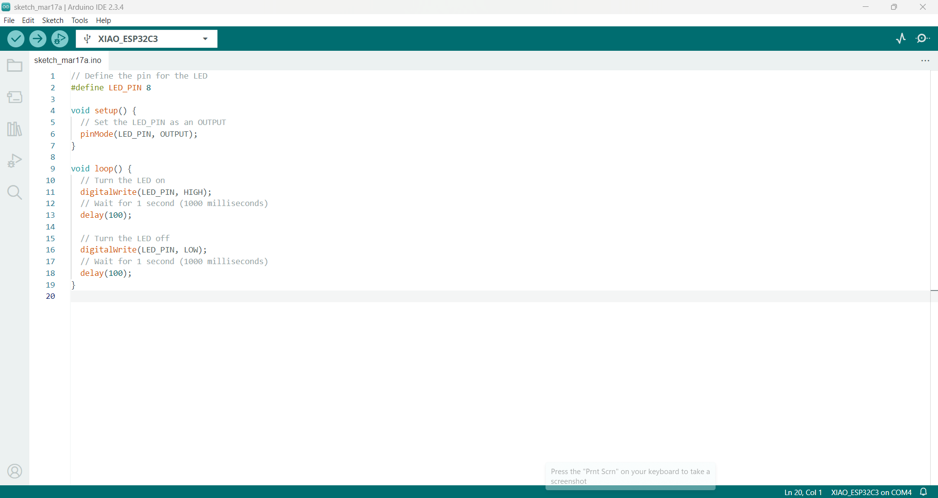
Next, I inserted the Blink code and assigned Pin 8 to control the LED.
|
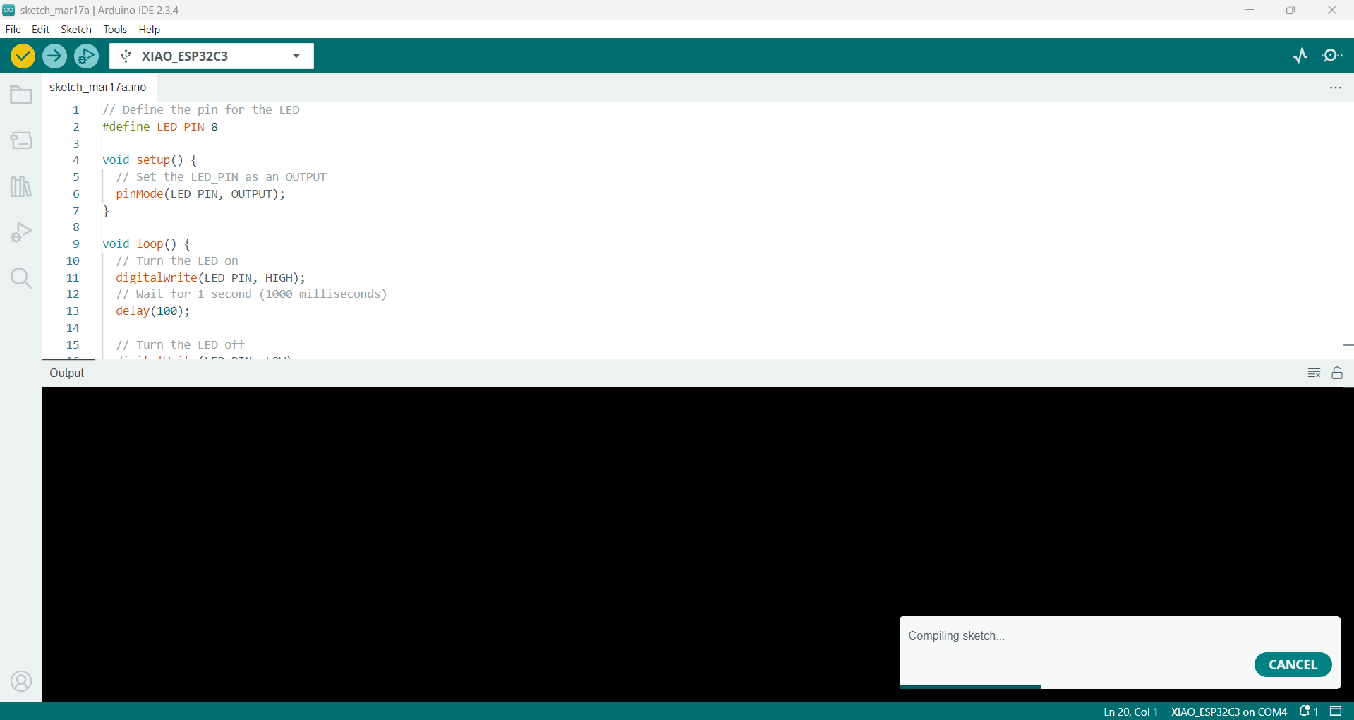
I proceeded to verify the code to ensure there were no errors or issues.
|
After successful verification, I uploaded the code to the microcontroller board.
|
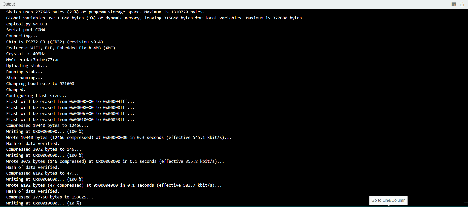
Currently in the process of uploading...
|
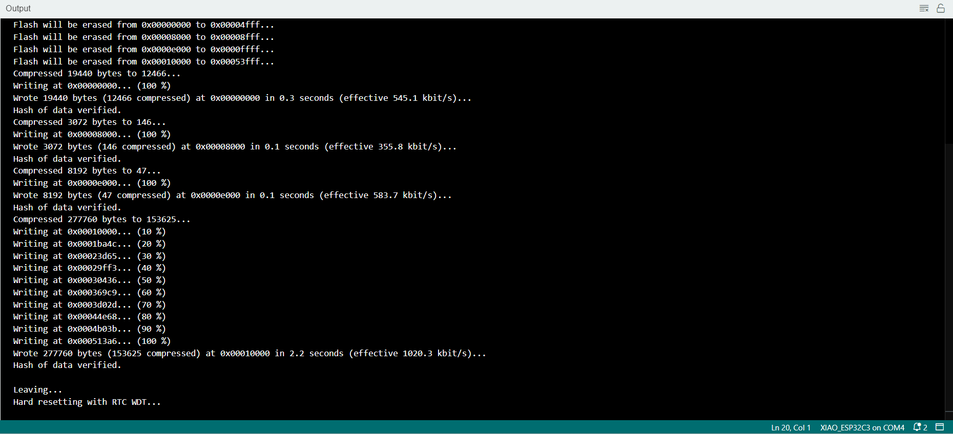
Upload in progress...
|
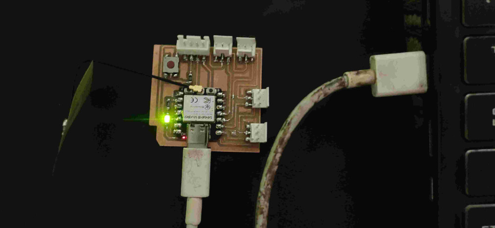
Here’s a photo of the LED in the blinking state, confirming the upload was successful.
|
Below is a video demonstration showing the LED blinking, as programmed.
|
📂 Original Files are Here
Tools Used in My Assignment