brief Insight of this week
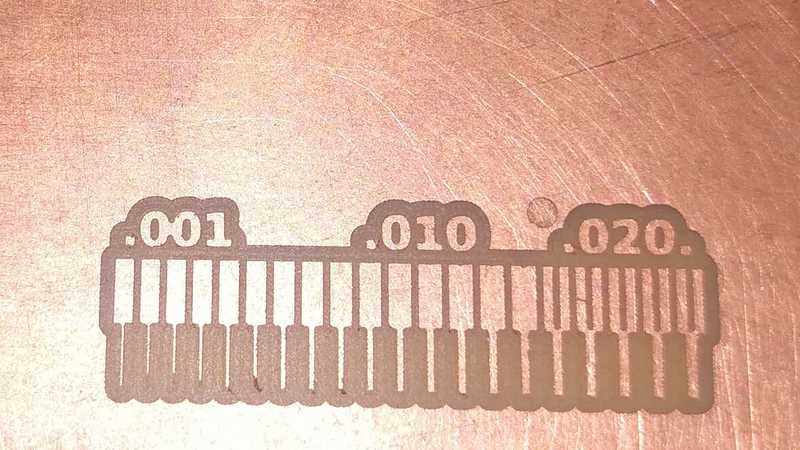
This week, we learned about electronics production. First, we understood the test rules required before PCB milling. To do this, we downloaded a test rule PNG file suggested by Neil from the Fab Academy website. Then, we used the Mods Online website to generate the toolpath. After completing these steps, we downloaded the necessary software for the PCB milling machine, connected it, and set the origin. Finally, we started the machine and initiated the cutting process using the generated toolpath file. Once the final print was completed, we analyzed and understood the test rules.
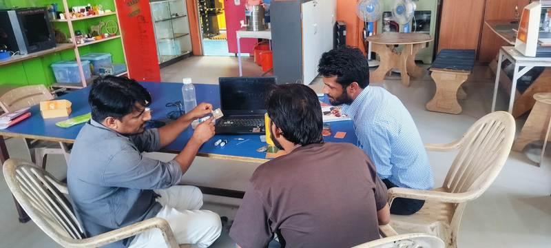
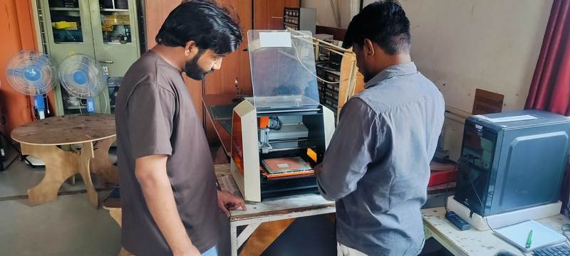
Heroshot of the Grop assignment
 |
.jpeg) |
|
|
|
 |
 |
|
|
|
About Electronics Production
Electronic production involves designing and manufacturing small electronic components such as resistors, transistors, and PCBs. This process includes designing the PCB, printing it, and assembling all the necessary components onto the board. Additionally, it is essential to ensure that all components are functioning correctly. Once the entire circuit is built, it undergoes thorough testing to verify its performance.
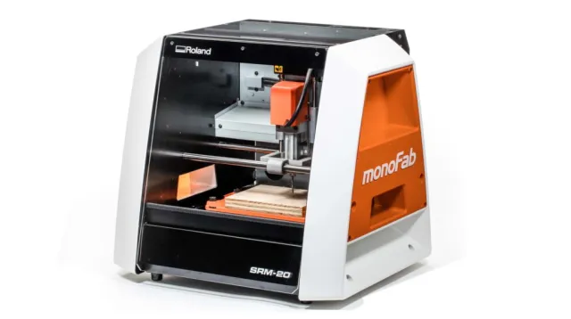
PCB Milling Machine SRM 20
PCB milling machine allows us to print a designed PCB by precisely cutting the circuit layout onto the board. Before milling, it is essential to generate a "toolpath file" for the PCB design. Once the toolpath is created, it can be loaded into the milling machine for the cutting process. This machine is used for engraving and cutting the PCB layout, ensuring accurate circuit traces. Different cutting bits can be used in the machine to perform various milling operations as required.
Roland MonoFab SRM-20 -
Key Features: -
 |
.jpg) |
|
|
|
Photos reference here
Specitaficion Sheet of the SRM20
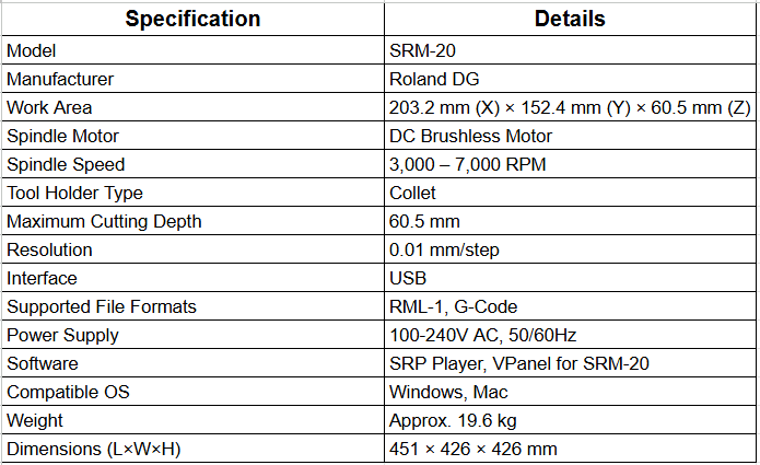 |
|
| Download PDF file here |
|
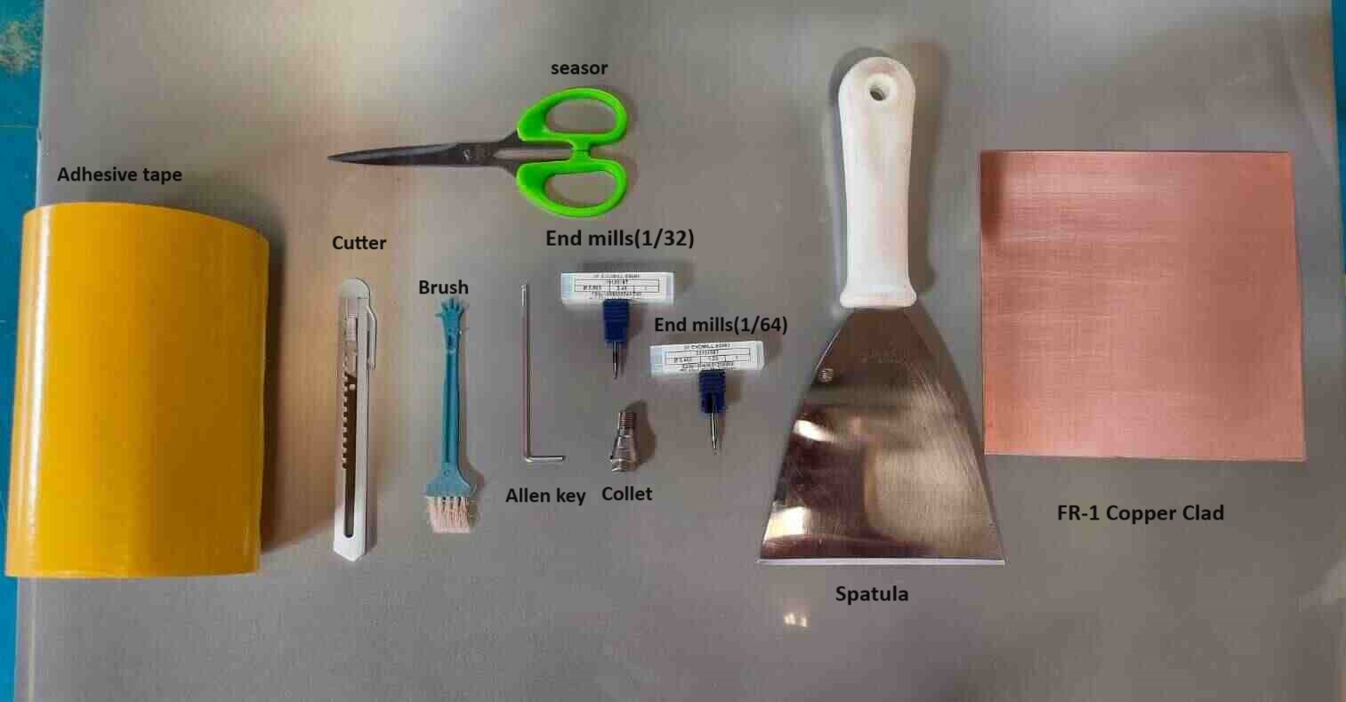
SRM-20 Machine Components
 |
 |
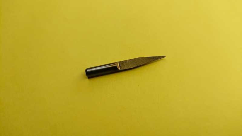
| V- Bit Used for engraving and fine detailing on PCB surfaces. |
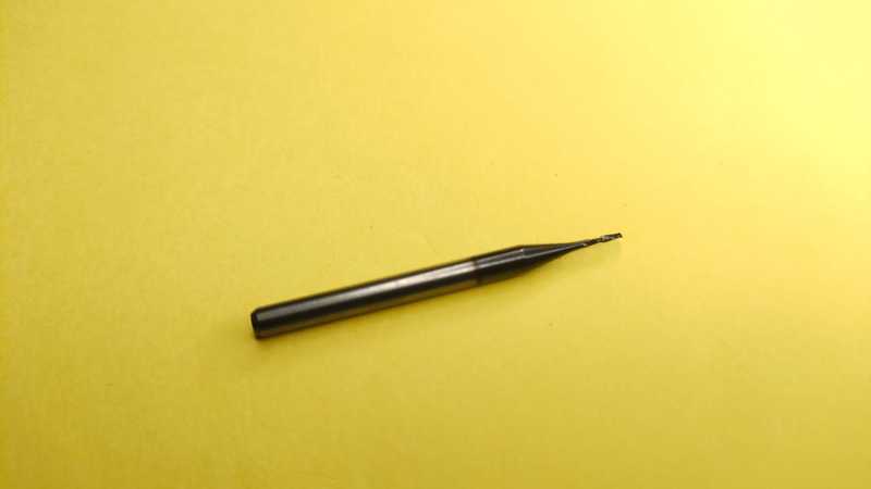
1/32 bitt Used for milling and cutting the outer profile of the PCB. |
 |
 |
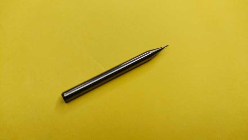
| 1/64 bitt Used for tracing fine circuit paths and creating precise traces on the PCB. |
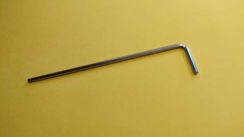
Allenkey Used for tightening and loosening screws on the spindle and collet holder. |
 |
|
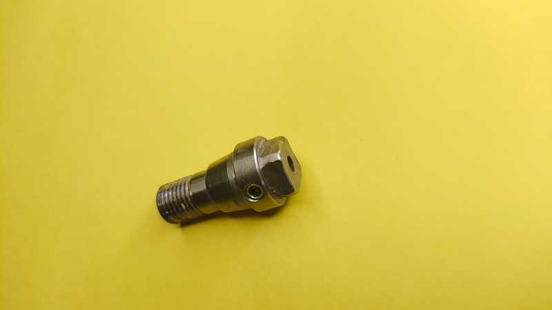
| Collet Holder Holds the milling bit securely in the spindle. Ensures the bit stays in place during the milling process for accurate cutting. |
|
PCB (Printed Circuit Board) Fabrication
PCB fabrication includes the entire process from designing the PCB to the final cutting and assembly. First, the PCB is designed, and then it undergoes various processes like printing, drilling, and etching using a milling machine. After that, a solder mask is applied to protect the copper traces. The milling machine is also used to create small holes in the PCB for component assembly. Once these steps are completed, the electronic components are mounted onto the PCB to form a complete circuit, followed by thorough testing to ensure proper functionality.
Type of PCB
Mods CE
"Mods CE" is an online platform used for generating toolpaths from "SVG files" for PCB milling and other fabrication processes. It allows users to convert design files into machine-readable formats, ensuring precise cutting and engraving. This platform supports various customizable settings such as tool diameter, cutting depth, and speed, making it highly useful for PCB fabrication, engraving, and other CNC-based applications.
Website link is here
Toolpath Generate Process
 |
 |
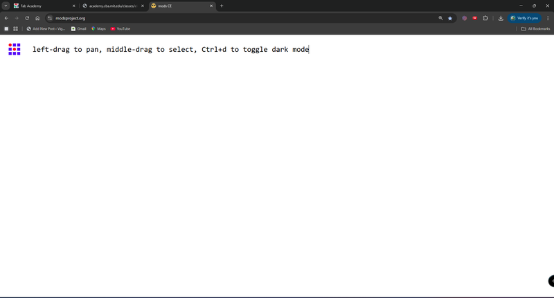
| First, visit the "MODS CE" website. |
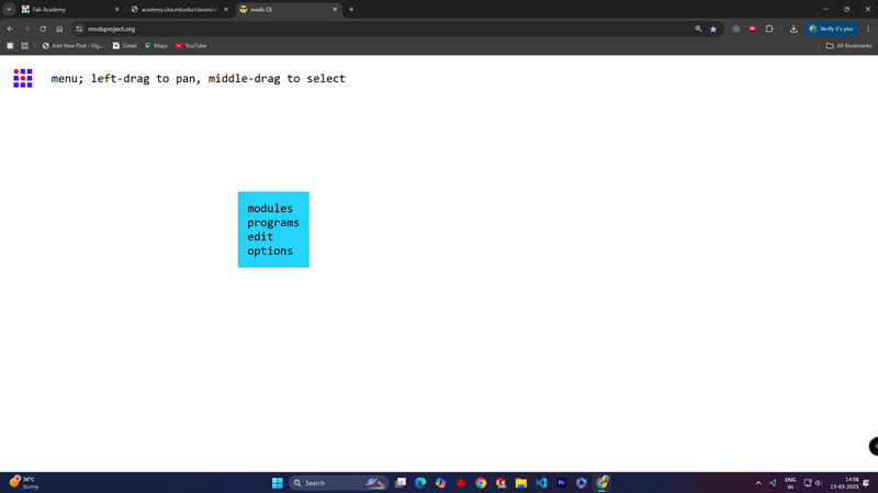
Next, "right-click" and select the programs from the menu. |
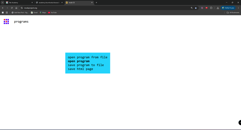 |
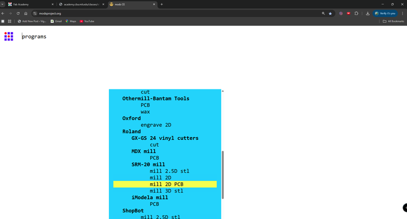 |
| Then, click on "Open Program." Ensure that PCB milling machine is properly connected with the device |
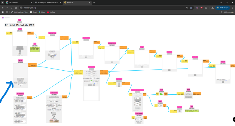
Now, go to the File menu, locate SRM-20 mill, and click on Mill 2D PCB. |
 |
 |
| After that, the process flow diagram will open. |
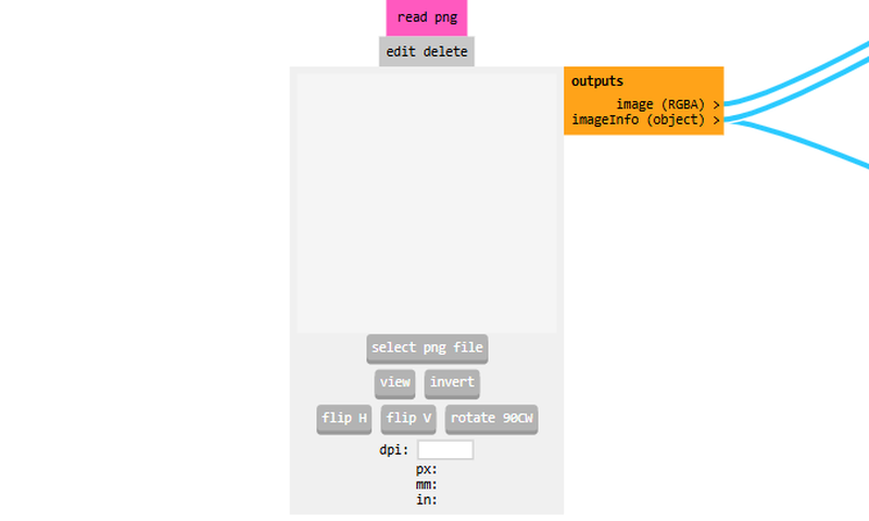
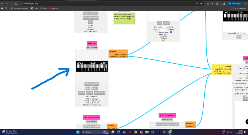
Now, load the PCB PNG file into the system clicking on "select png file". |
 |
 |
| Once the file is loaded, it will be visible on the interface. |
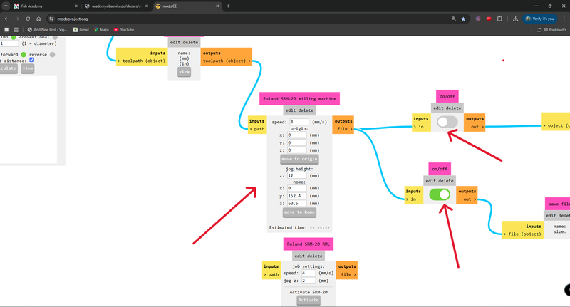
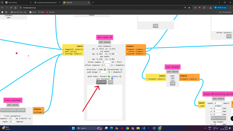
Now, set the XYZ origin to 0, as the machine will be operated through V Panel software. Adjust the settings accurately as per the reference in the provided image. |
 |
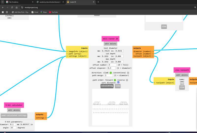 |
| After completing all the settings, click on Calculate to proceed. |
Now, the calculation process will begin. |
After all thease a .rml file will be downloaded. This file contains the toolpath data required for the SRM-20 PCB milling machine to execute the cutting or engraving operation.
Tools
 |
|
|
|
|
fixturing
We used FR1 (Coper Clad) PCB for tracing circuit paths during the milling process. FR1 is a cost-effective, heat-resistant material commonly used for prototyping and single-layer PCBs. It provides good mechanical strength and electrical insulation, making it ideal for rapid PCB fabrication.
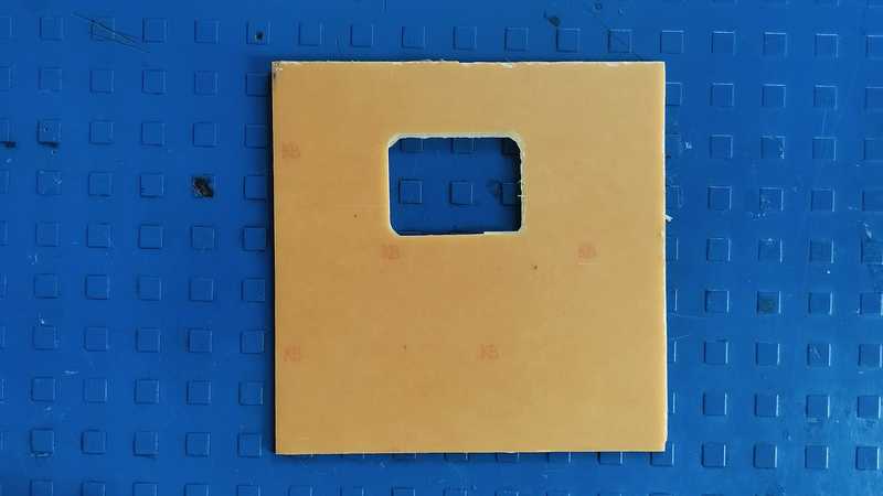 |
 |
| FR-1 Copper Clad PCB |
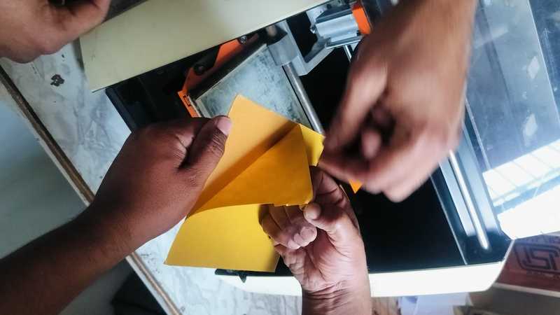
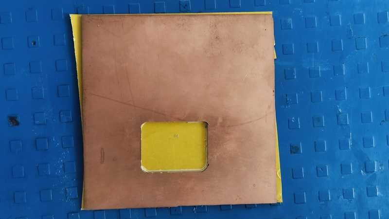
Applying double-sided tape to the "FR-1 Copper Clad PCB" ensures that it is securely fixed in place on the milling machine for precise and stable milling. |
 |
 |
| The tape has been properly applied, and any excess tape extending from the edges has been trimmed off. |
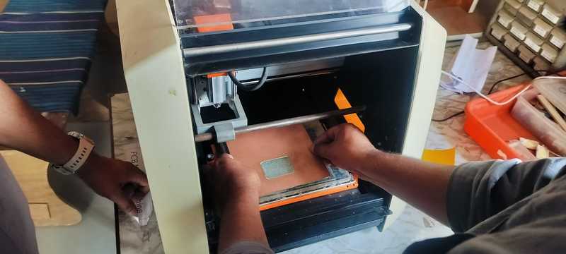
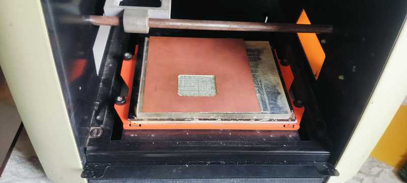
Placing the PCB in the milling machine properly and ensuring it is securely positioned. |
 |
|
| Now, the PCB is properly fitted in the milling machine's work area. |
|
V Panel Software
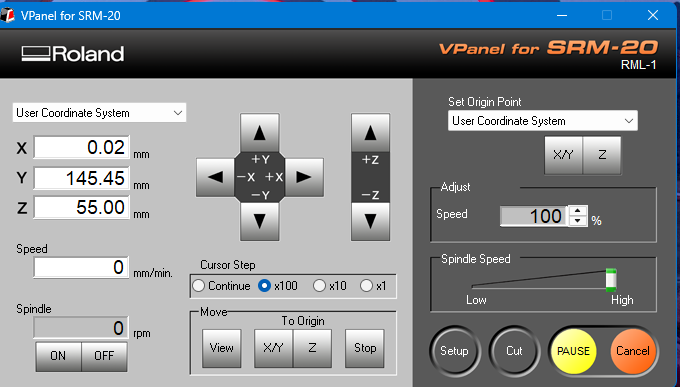
VPanel (Virtual Panel) is the control software used for operating the Roland MonoFab SRM-20 CNC milling machine. It provides a user-friendly interface to manage and control the milling process.
Key Features
 |
 |
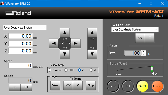
| First, open the V-Panel software. |
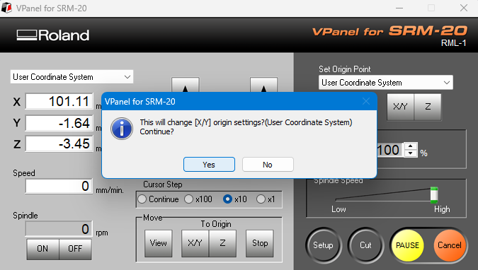
Setting the machine's origin point. |
 |
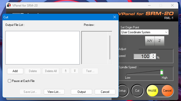 |
| Now, the machine's XYZ origin has been successfully set. |
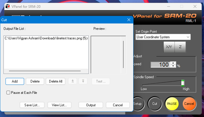
Now, click on the Cut option and load the file. |
 |
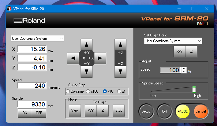 |
| Now, the file has been successfully loaded. Click on the "Output" option to start the cutting process. |
Now, the milling machine has started operating. |
Cutting and Drilling
Cutting File
 |
 |
| Exterior |
Interior |
 |
%20Assignment%208_result.jpg) |
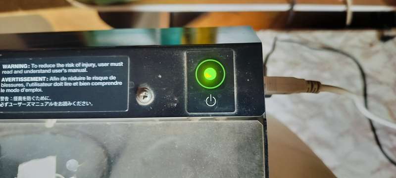
| First, turn on the milling machine and connect it through cable to device |
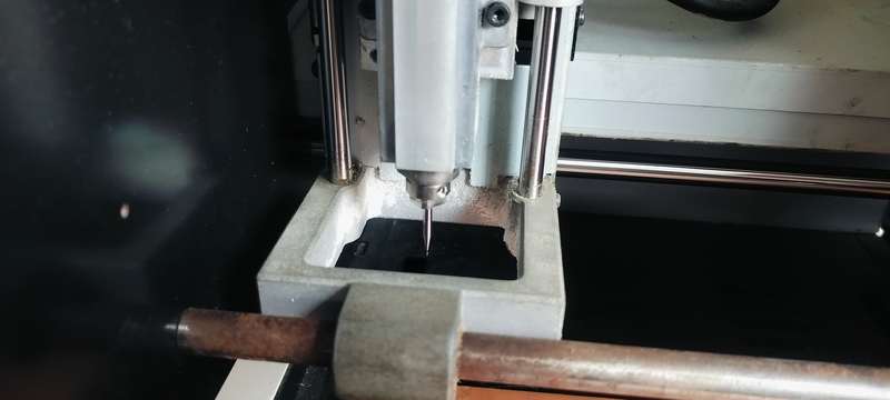
After that, securely tighten the end mill. |
 |
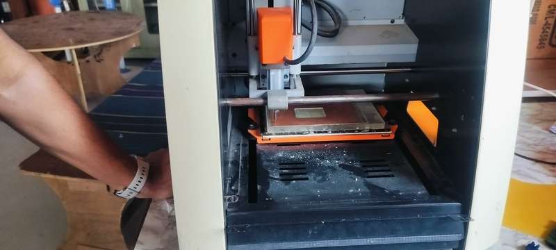 |
| After securely tightening the end mill, accurately set the origin for the FR1 PCB and the end mill, then perform the gravity adjustment. |
Now started the milling Exterior file. |
 |
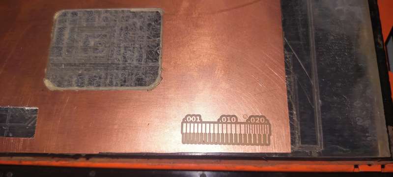 |
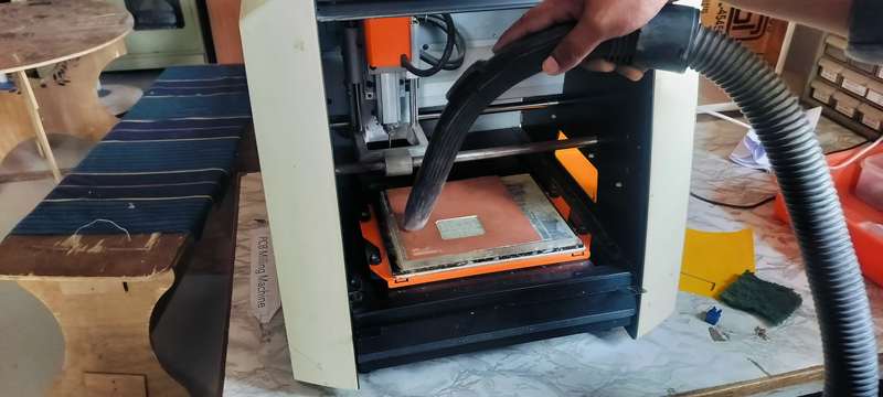
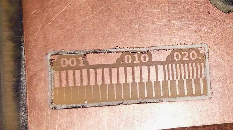
| After the Exterior milling is complete, clean the FR1 PCB using a vacuum cleaner. |
Properly cleaned. |
 |
.jpeg) |
| After that, start the milling of the interior file. |
After the final cutting is complete, remove it from the workspace and clean it. |
|
|
|
Conclusaion
This week, we successfully completed the PCB milling process while learning about important tools and software. We explored "Mods CE", an online tool for generating toolpaths, and installed "VPanel software" to operate the milling machine. During this assignment, we understood the different parts of the milling machine and their functions, such as end mills, collets, Allen keys, and double-sided masking tape. After that, we set up the machine, secured the end mill, and accurately set the origin for the FR1 PCB. We then performed gravity adjustments before starting the cutting process. Once the cutting was complete, we cleaned the PCB properly using a vacuum cleaner. After that, we milled the interior file and finally removed the PCB from the workspace for a final cleaning. Overall, this week helped us improve our understanding of PCB milling, machine operation, and essential tools, making the process smoother and more efficient.