Output Devices
Learning Experience
During this week, I gained extensive hands-on experience in hardware interfacing, microcontroller programming, and printed circuit board (PCB) design. After designing the circuit using KiCad, I successfully fabricated the PCB with the SRM-20 milling machine, which enhanced my understanding of the fabrication workflow. I programmed the ATtiny1614 microcontroller using the Arduino IDE and integrated it with various output devices, such as servo motors, LEDs, and an I2C LCD display. Throughout the process, I encountered and resolved several technical challenges, including missing ground connections and issues related to programming without the UPDI (Unified Program and Debug Interface) pin. These debugging and troubleshooting activities significantly deepened my understanding of embedded systems. Additionally, I explored techniques for efficient power management and implemented real-time monitoring solutions to optimize system performance. This comprehensive learning experience has significantly strengthened my foundation in electronics and embedded system design, preparing me for more advanced projects in automation and the Internet of Things (IoT).
Key Accomplishments
✅PCB Design & Fabrication: Using KiCad and an SRM-20 milling machine, a bespoke PCB was designed and machined.
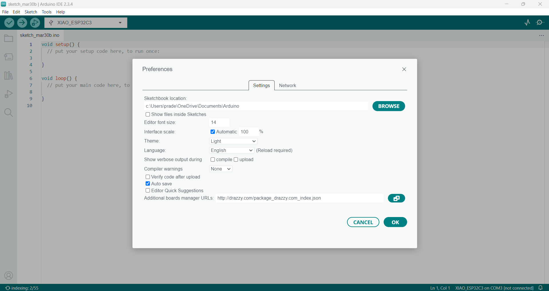
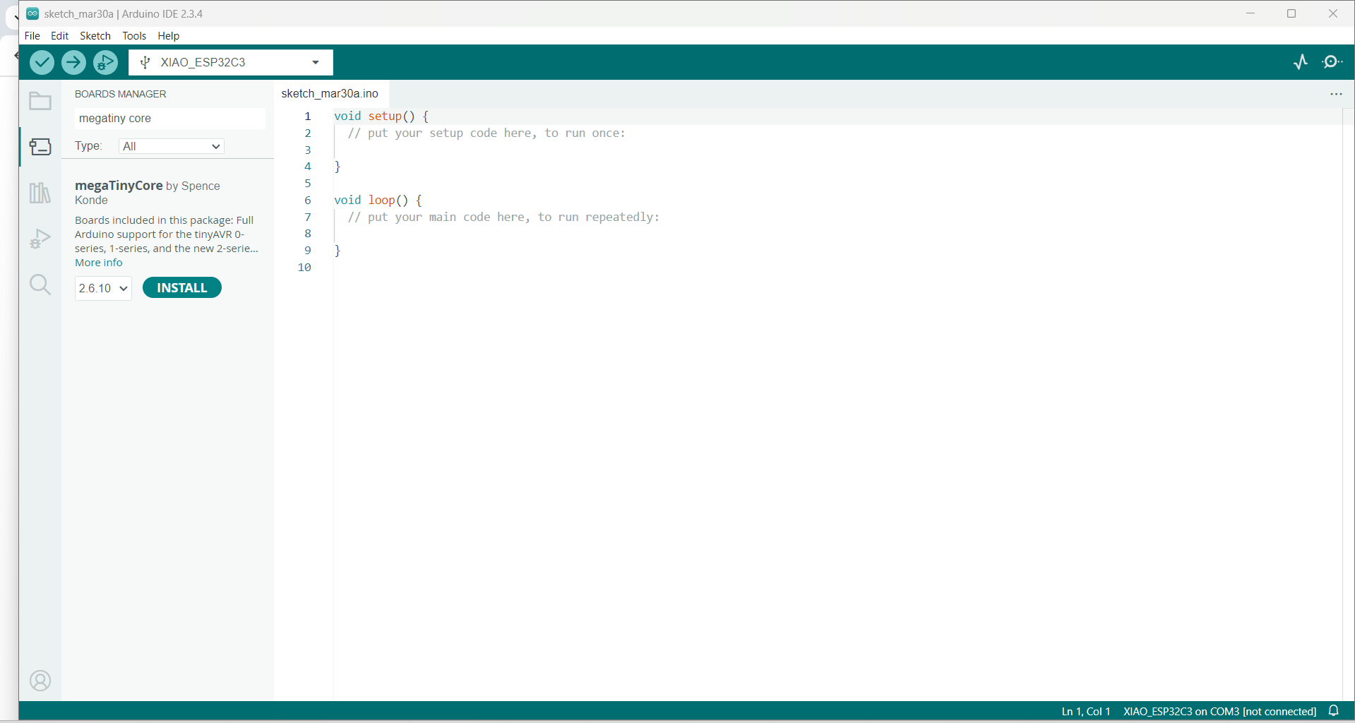
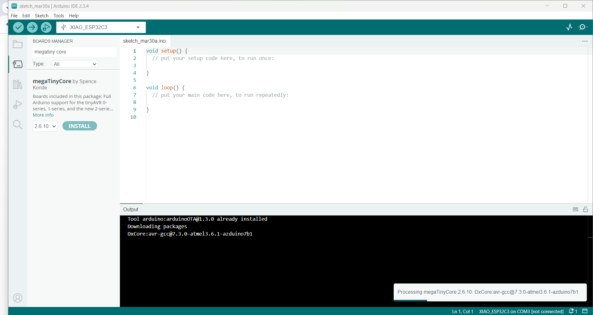
✅Programming Microcontroller: The ATtiny1614 was successfully programmed using the Arduino IDE and MegaTinyCore.
✅The ATtiny1614 was used to interface the SG90 servo motor, MG996R servo motor, and 16x2 I2C LCD display as output devices.
✅Debugging and troubleshooting: Fixed problems such as UPDI pin bypassing for programming and missing ground connections.
✅Power Management: To effectively operate servo motors, an external 5V power source was optimized.
✅Real-time Monitoring: While operating, the servo motor angles were dynamically displayed on an I2C LCD.
✅Understanding of Embedded Systems: Acquired practical knowledge of firmware development, circuit routing, and electronics design.
Task: Output Devices
Group assignment:
Measure the power consumption of an output device.
Document your work on the group work page and reflect on your individual page what you learned.
Individual project:
Add an output device to a microcontroller board you’ve designed and program it to do something.
Individual Assignment
During this week’s assignment, I have chosen to work with a servo motor and an LCD display.
I plan to design and fabricate a custom PCB that includes the ATtiny1614 microcontroller.
In addition to building the board, I will explore and document detailed information about various output devices.
Output Devices
Output devices are essential components in any embedded or computer-based system. These devices convert electrical signals into human-perceivable outputs such as light, sound, motion, or display. Their primary function is to provide feedback or perform specific tasks in response to system commands. Commonly used output devices include LEDs, LCDs, buzzers, speakers, motors, and relays. These are widely applied in fields like automation, robotics, and embedded systems to deliver visual or auditory feedback, execute mechanical operations, and signal system alerts.
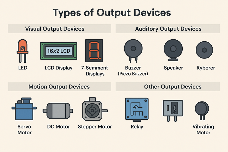
Types of Output Devices
Visual Output Devices
- LEDs (Light Emitting Diodes): Commonly used to indicate status, power, or alerts by emitting light in various colors.
- LCD Displays: These include 16x2 alphanumeric displays, OLEDs, and TFT screens, which are used to show both text and graphical information.
- Seven-Segment Displays: Ideal for displaying numeric values, often found in meters, digital clocks, and counters.
- RGB LEDs: Used in decorative lighting and color-coded indicators to convey different statuses through color variations.
Auditory Output Devices
- Buzzers: These are typically piezoelectric devices used to generate beeping sounds for alerts, alarms, and notifications.
- Speakers: Employed for playing recorded or synthesized audio, such as voice prompts or sound effects.
Motion-Based Output Devices
- Servo Motors: These provide precise angular control and are extensively used in robotic arms, actuators, and automated mechanisms.
- DC Motors: Commonly used to generate rotary motion in applications like fans, small vehicles, and appliances.
- Stepper Motors: Ideal for precision motion control in devices such as 3D printers and CNC machines.
Other Output Devices
- Relays: Electromechanical switches that allow low-power circuits to control higher voltage devices like lights, fans, or motors.
- Vibration Motors: These are small motors that produce vibration and are typically used in mobile devices for tactile feedback.
Reference: Original explanation created for this project using insights from general electronics and embedded systems knowledge.
PCB Design
For designing the Printed Circuit Board (PCB) in KiCad, I used the following components:
- ATtiny1614 microcontroller
- Two 4-pin connectors
- One 3-pin connector
- Two Light Emitting Diodes (LEDs)
- Two resistors
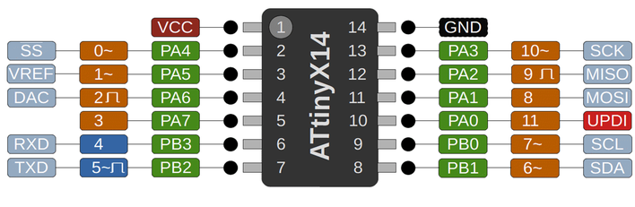
ATtiny1614 Pin Diagram and Datasheet
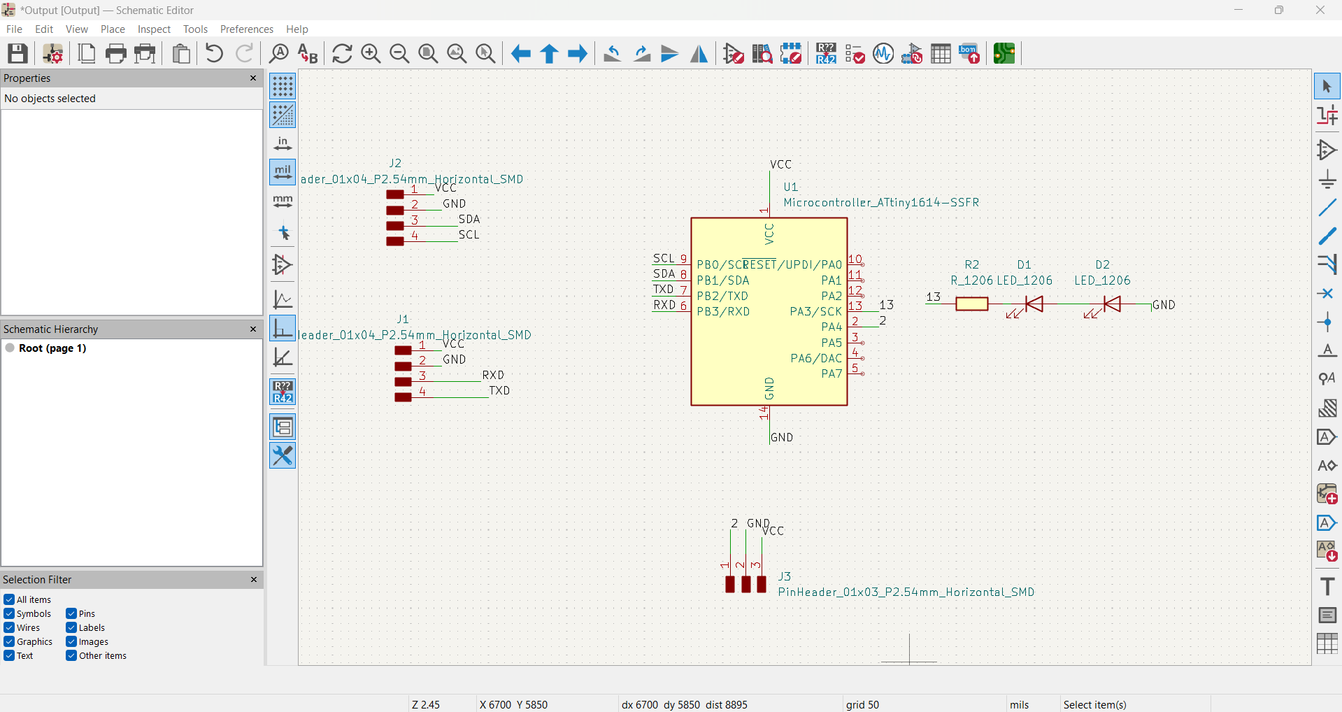
Schematic Diagram Created in KiCad
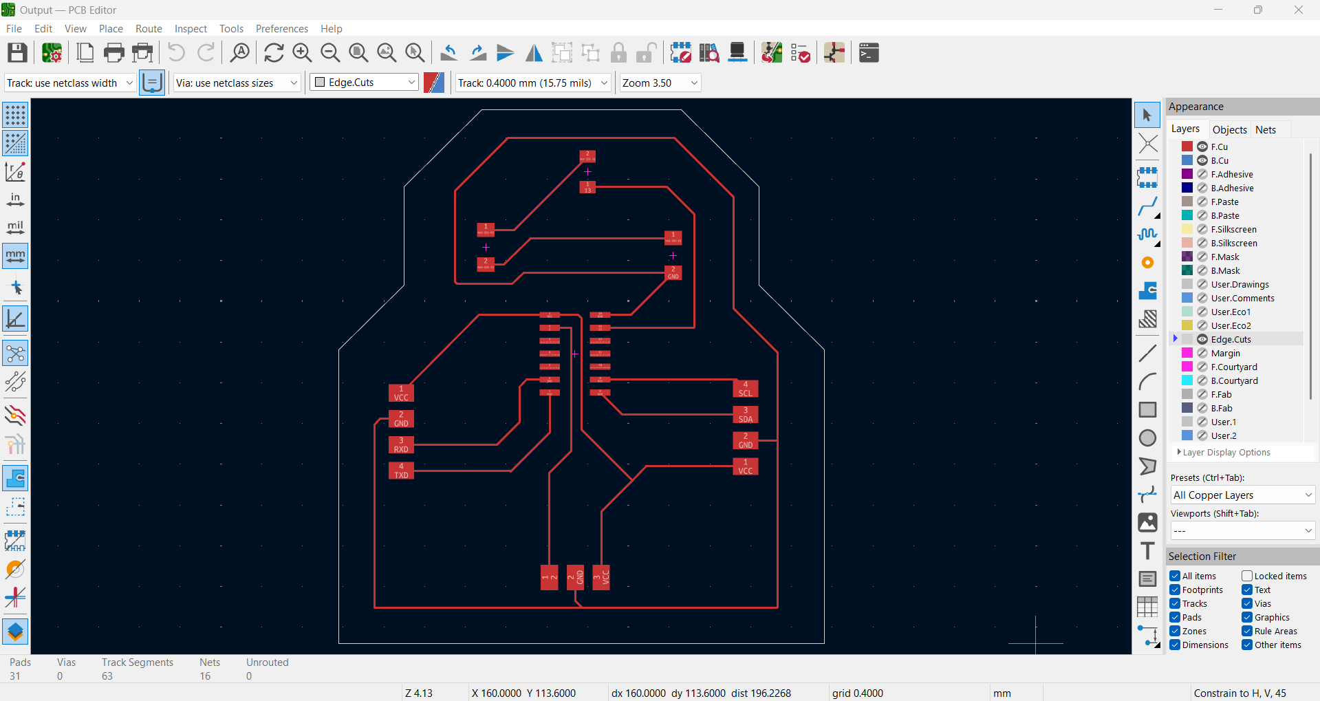
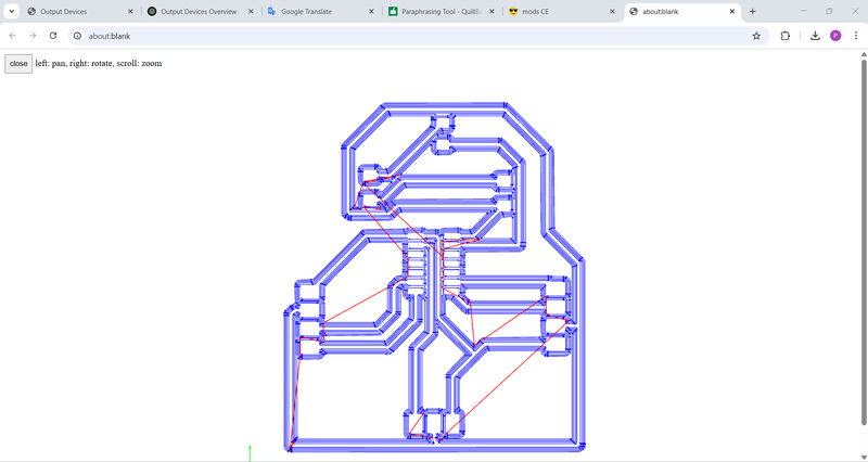
PCB Routing and Edge Cut View
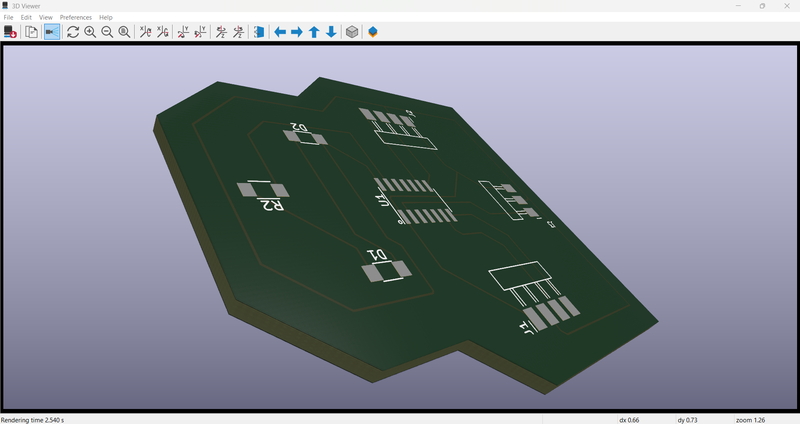
3D View of the Designed PCB
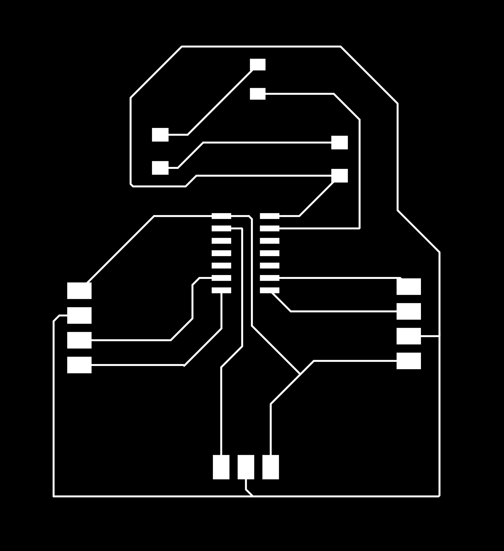
Traces Layout

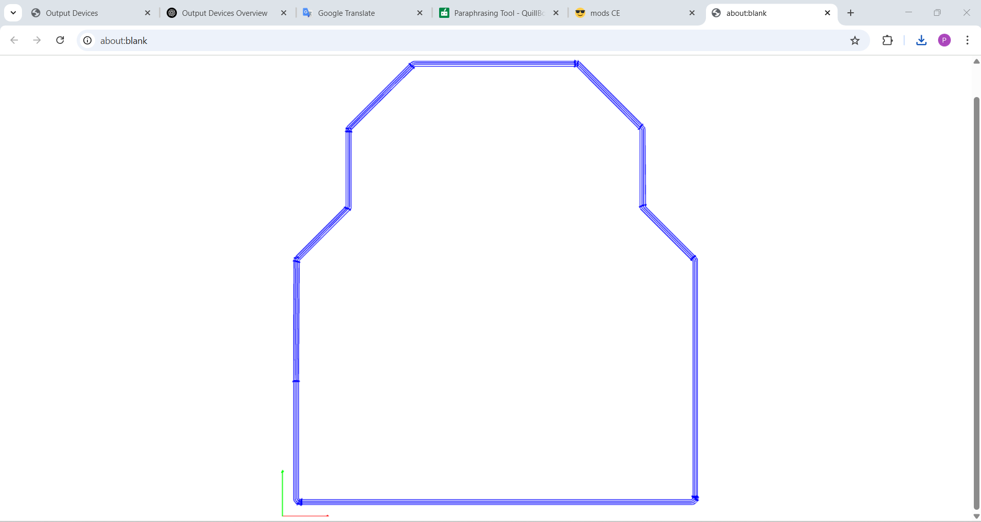
Edge Cut Path
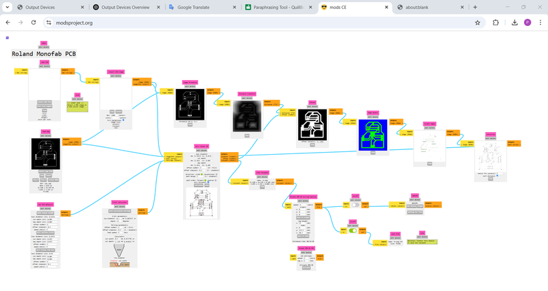
G-Code Process for Traces
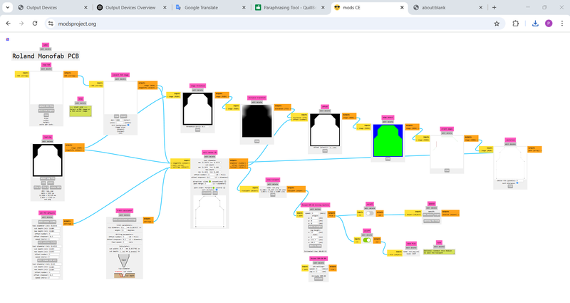
G-Code Process for Edge Cut
Final G-Code for Traces
Final G-Code for Edge Cut
To explore the entire design workflow, including schematic creation, footprint assignment, routing, and generating fabrication files, please visit my
Electronics Design Assignment page, where I have documented the process in detail.
PCB Milling, Cutting, and Soldering Process
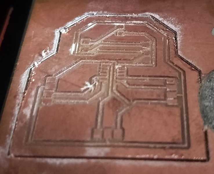
To carry out the PCB milling and cutting process, I utilized the SRM-20 milling machine. I began by generating the required G-code files, which allowed me to successfully mill and fabricate my custom-designed PCB.
The first step involved engraving the internal traces of the PCB. This ensured accurate circuit paths were etched onto the board according to my design specifications.
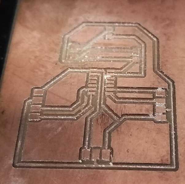
In the next stage, I performed the outline cutting of the PCB to give it the desired shape by trimming the edges cleanly and precisely.
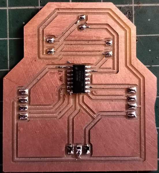
After the milling and cutting were complete, I proceeded with the soldering process. I carefully placed and soldered the Integrated Circuit (IC) and other necessary components onto the board using a soldering iron.
This marked the completion of my PCB, with all components properly soldered and the board ready for testing and further integration.
Testing the Microcontroller Board
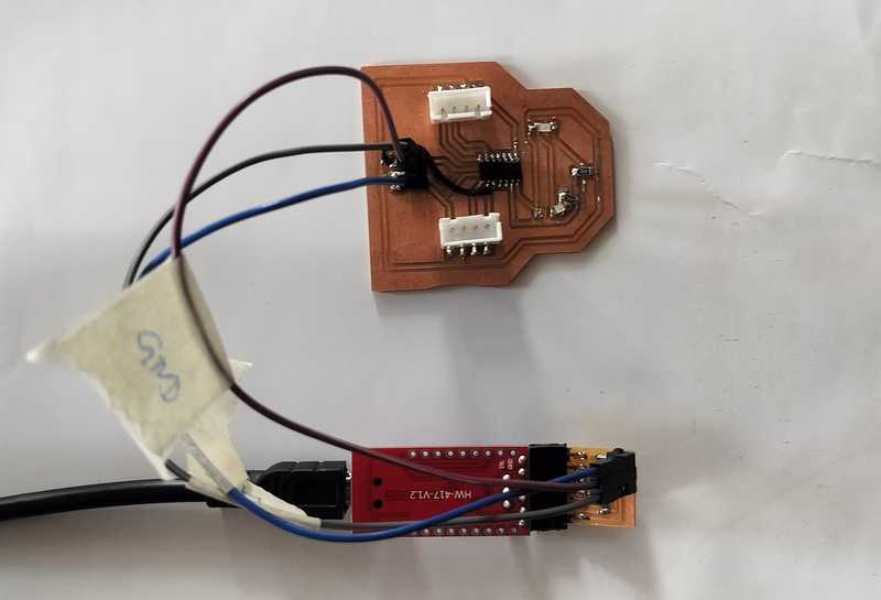
To begin with, I tested my custom microcontroller board. Initially, I realized that I had not added the UPDI (Unified Program and Debug Interface) pin to the board layout. As a result, I had to manually bypass this pin and connect my sensor pin directly in order to program the board using my external programmer.
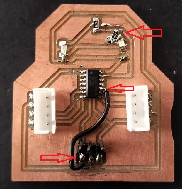
- PA0 - Pin 11 - UPDI - 0 iN0
- I had also connected two LEDs for output testing. However, one of the LEDs was not functioning because it was not properly connected to the ground. After identifying this issue, I corrected the connection, and the LED started working as expected.
TTL Converter and Programming Setup
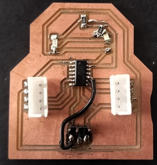
For programming the board, I used a TTL (Transistor-Transistor Logic) converter. To facilitate the connection between the programmer and my microcontroller board, I designed a compact custom circuit. This circuit acts as an interface that allows seamless communication during the uploading of the firmware.
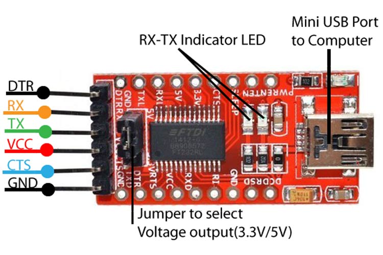
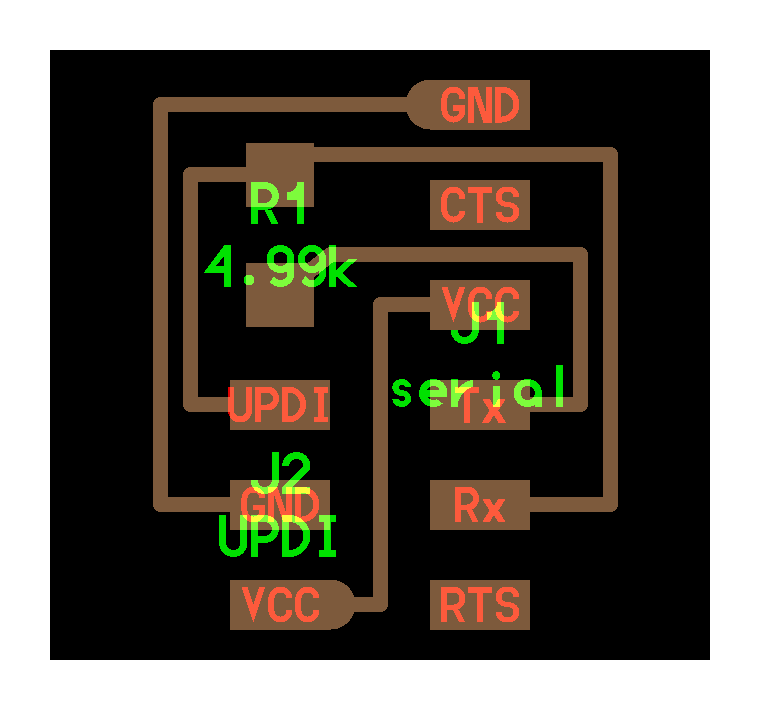
Serial UPDI 3-Pin Interface Board
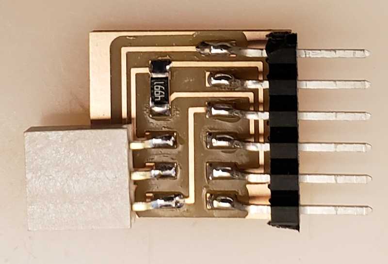
Component Placement

PCB Traces

Internal Layout
Pin Mapping Overview
| ATtiny1614 Pin |
TTL Converter Pin |
3-Pin UPDI Programmer |
| VCC (Pin 1) |
VCC (3.3V / 5V) |
VCC |
| GND (Pin 14) |
GND |
GND |
| UPDI (Pin 11) |
TX of TTL (via 4.7kΩ resistor) |
UPDI |
For more technical details and reference, you can visit the official Fab Academy page on embedded programming:
Reference Website – Embedded Programming – Serial UPDI 3-Pin
Re-Testing the Board
Once all connections were verified, I re-tested the board by following a step-by-step process to upload the program using the TTL-UPDI interface. The images below show each step of the process:
Step 1: Connecting the board to the programmer
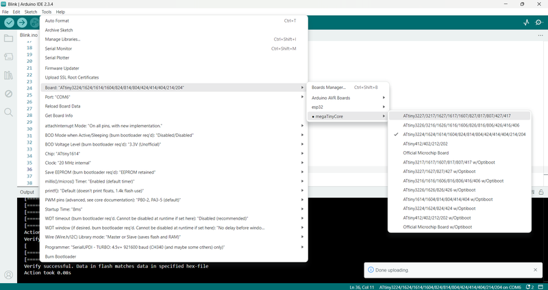
Step 2: Verifying board recognition
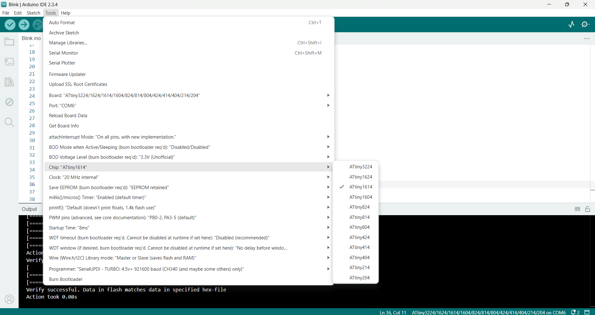
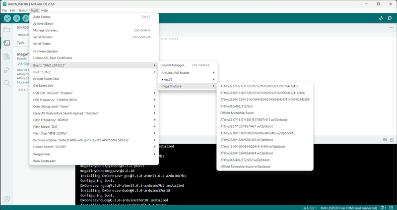
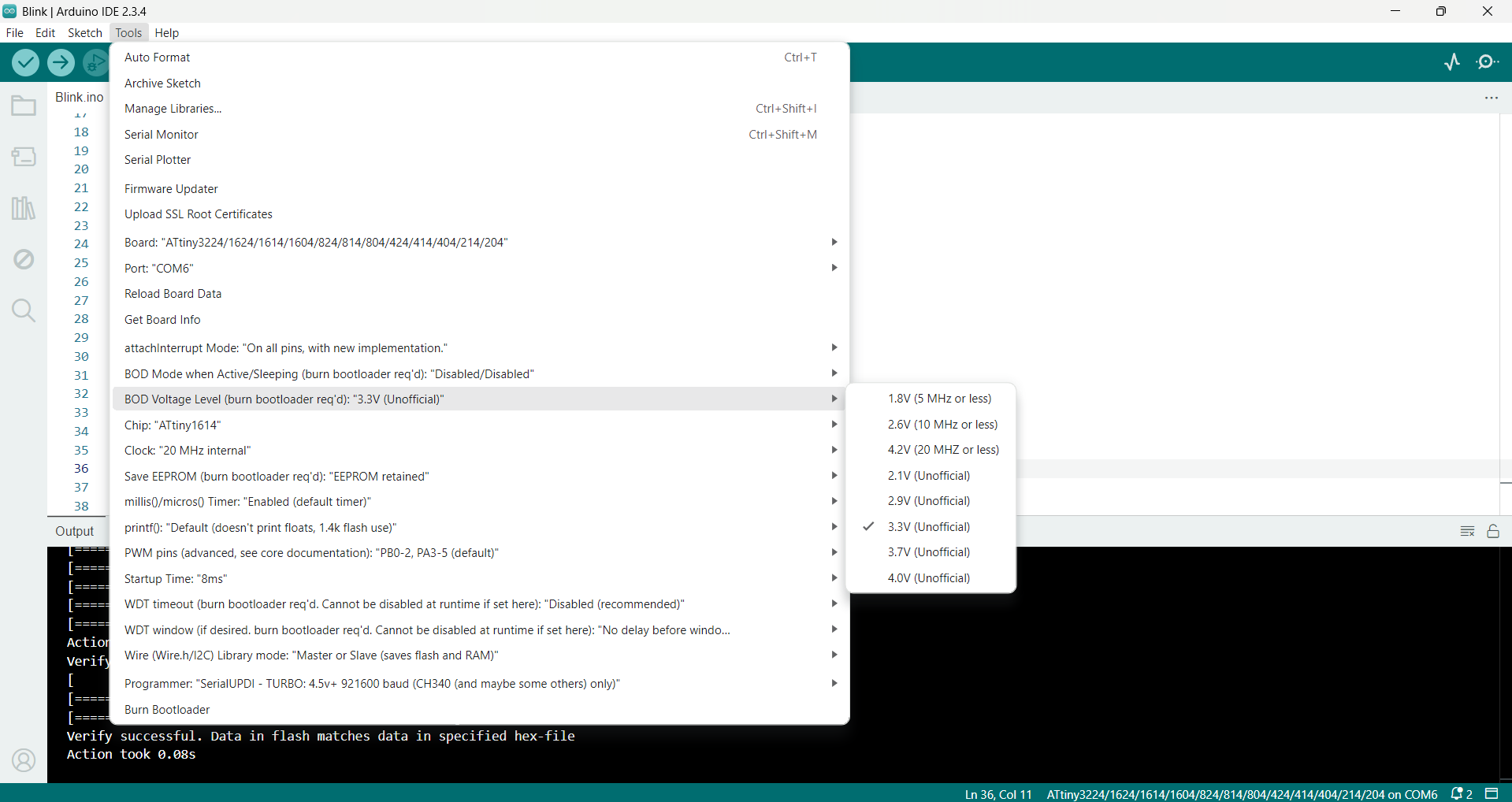
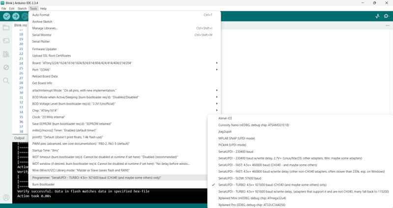
Step 3: Selecting the correct port and board
Step 4: Compiling the code
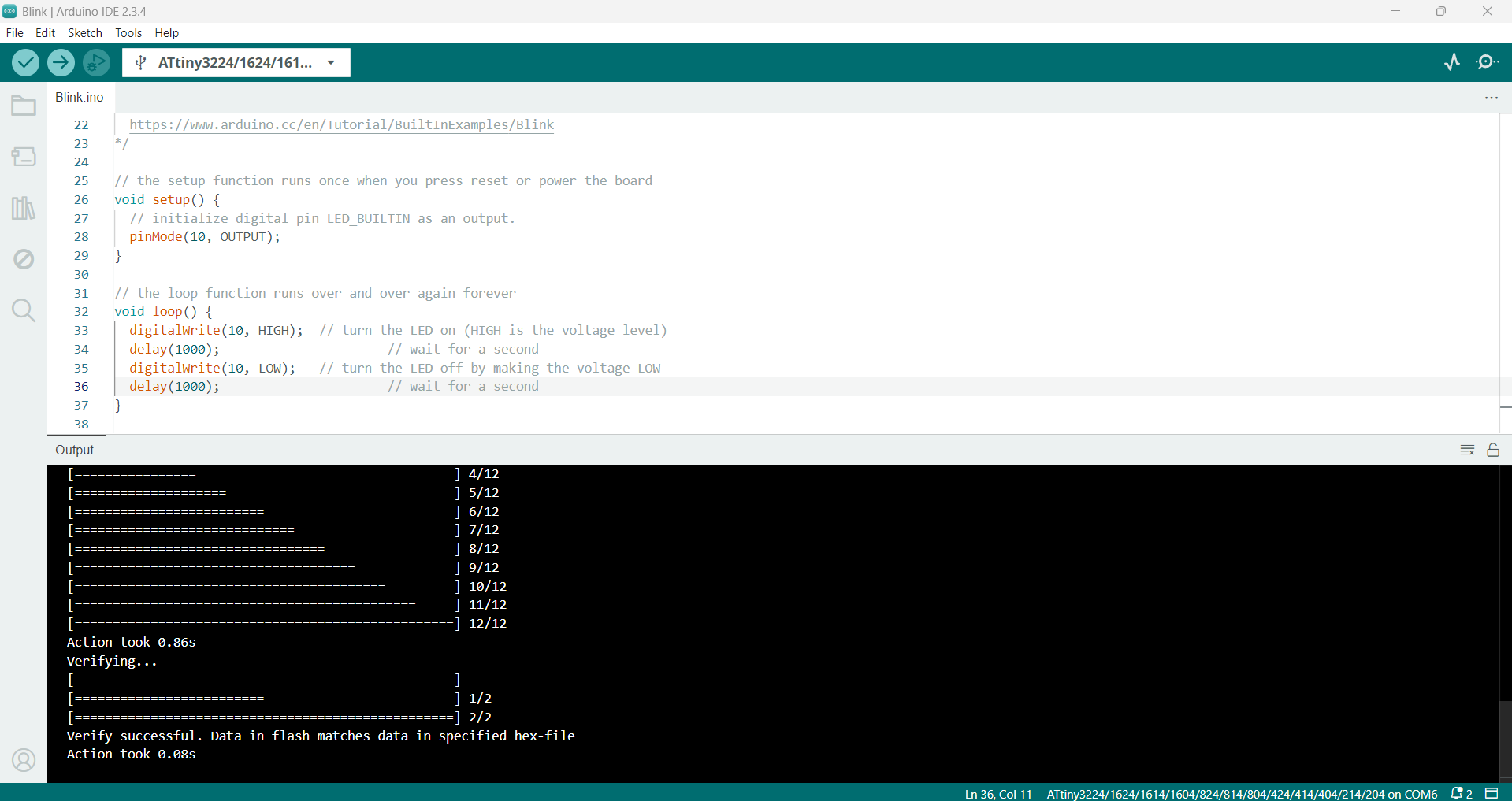
Step 5: Uploading the firmware
Uploading the Code
If the onboard LED is blinking after the upload, it confirms that the board is successfully programmed and working properly.
About the Servo Motor
A servo motor is an advanced rotary or linear actuator specifically designed to accurately control position, speed, and acceleration. It functions using a closed-loop system, which incorporates a feedback mechanism—typically a potentiometer or encoder—to maintain high precision and responsiveness. Due to their exceptional control and reliability, servo motors are widely used in fields such as robotics, industrial automation, CNC (Computer Numerical Control) machinery, and remote-controlled vehicles. Each servo motor generally consists of a motor unit, control circuitry, drive mechanism, and a feedback system. Depending on the application, various types of servo motors—such as DC servo motors, AC servo motors, and stepper-based servo systems—can be selected for optimal performance.
Key Features of a Servo Motor:
- Closed-Loop Control: Utilizes a feedback system (encoder or potentiometer) to continuously adjust motor output for maximum accuracy.
- High Precision: Offers fine control over parameters like torque, speed, and angular position.
- Compact Design: Available in small form factors, making them ideal for embedded or space-constrained applications.
- Torque at Low Speeds: Capable of delivering substantial torque even when operating at low rotational speeds.
- Quick Response: Provides rapid reaction to control signals, ensuring timely and smooth operation.
Types of Servo Motors:
- DC Servo Motor: Commonly used in hobby electronics and small devices, these motors run on direct current power sources.
- AC Servo Motor: Preferred in industrial and commercial settings for their efficiency and power, these motors operate on alternating current.
- Positional Rotation Servo: Designed to rotate only within a fixed angle range, typically from 0° to 180°.
- Continuous Rotation Servo: Functions like a standard DC motor and is capable of rotating continuously in either direction.
Servo Motor Pinout
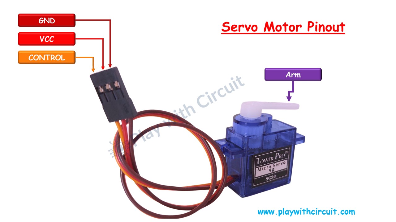
SG90 Servo Motor with ATtiny1614
The following table shows the proper pin connections between the SG90 servo motor and the ATtiny1614 microcontroller:
| Servo Motor Pin |
ATtiny1614 Connection |
Description |
| VCC (Red) |
External 5V Power Supply |
Provides the necessary operating voltage to the servo motor. Avoid powering directly from the ATtiny1614. |
| GND (Black/Brown) |
GND (Shared Ground) |
Establishes a common ground connection between the servo and microcontroller. |
| Signal (Yellow/White) |
PA3 (Pin 6) |
Sends the PWM signal to control the servo’s rotation. |
Arduino Code:
 #include <Servo.h>

Servo myServo;

void setup() {
  myServo.attach(6); // Connects the servo to pin PA3 (pin 6)
}

void loop() {
  myServo.write(0);     // Move to 0 degrees
  delay(1000);          // Wait 1 second
  myServo.write(90);    // Move to 90 degrees
  delay(1000);          // Wait 1 second
  myServo.write(180);   // Move to 180 degrees
  delay(1000);          // Wait 1 second
}
Explanation of the Code:
- #include <Servo.h>: This line imports the Servo library required for controlling servo motors in Arduino.
- Servo myServo;: Creates an object named
myServo which will be used to control the servo.
- myServo.attach(6);: Attaches the servo motor’s signal pin to pin 6 (PA3) on the ATtiny1614.
- myServo.write(angle);: Commands the servo to rotate to specified angles: 0°, 90°, and 180°, with a 1-second delay between each movement.
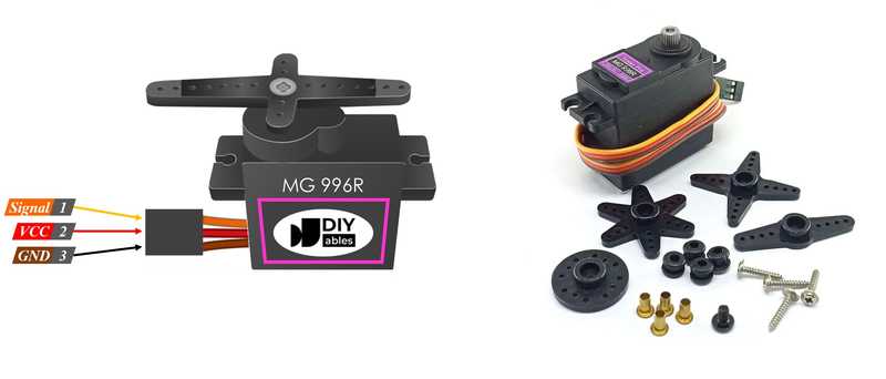
MG996R Servo Motor Interface with ATtiny1614
The table below shows the correct wiring connections between the MG996R Servo Motor and the ATtiny1614 microcontroller:
| Servo Motor Pin |
ATtiny1614 Connection |
Description |
| VCC (Red) |
External 5V Power Source |
This pin should be connected to an external 5V power supply. The servo motor requires more current than the ATtiny1614 can provide directly. |
| GND (Black/Brown) |
GND (Common Ground) |
This is the ground connection, which should be shared between the ATtiny1614 and the external power supply. |
| Signal (Yellow/White) |
PA3 (Pin 6 on ATtiny1614) |
This pin receives the PWM (Pulse Width Modulation) signal used to control the servo motor’s position. |
Arduino Code:
#include <Servo.h>

Servo myServo;

void setup() {
  myServo.attach(6); // Attach servo signal to pin PA3 (pin 6 on ATtiny1614)
}

void loop() {
  myServo.write(0);     // Move to 0°
  delay(1000);          // Wait for 1 second
  myServo.write(90);    // Move to 90°
  delay(1000);          // Wait for 1 second
  myServo.write(180);   // Move to 180°
  delay(1000);          // Wait for 1 second
}
Code Explanation:
#include <Servo.h> – This line includes the Servo library, which simplifies controlling servo motors in Arduino.Servo myServo; – Declares an object of the Servo class named myServo.myServo.attach(6); – Attaches the servo control pin to PA3 (pin 6) of the ATtiny1614.myServo.write(angle); – Sends commands to rotate the servo to specific angles (0°, 90°, and 180°) with a 1-second delay between movements.
This code and setup were implemented with the help of ChatGPT and guidance from Ramesh.
16x2 LCD Display Module + ATtiny1614
About the 16x2 LCD Display Module
The 16x2 LCD display module is widely used in electronic projects for its ability to display 16 characters per line over two lines. It is commonly employed in projects involving microcontrollers such as Arduino, ESP32, Raspberry Pi, and PIC. The module operates based on the Hitachi HD44780 controller, making it easy to integrate into various systems.
Key Features of the 16x2 LCD
- Display Size: 16 characters × 2 lines
- Operating Voltage: 4.7V – 5.3V (Typically 5V)
- Controller IC: HD44780
- Interface: Parallel (4-bit or 8-bit mode), or I2C (with an adapter)
- Backlight: LED backlight (available in blue or green)
- Contrast Adjustment: Controlled via a potentiometer
- Character Font: 5×8 or 5×10 dot matrix
- Power Consumption: Low
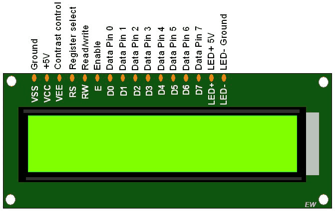
Pin Configuration of the 16x2 LCD
| Pin No. |
Name |
Function |
| 1 |
VSS |
Ground (0V) |
| 2 |
VCC |
Power Supply (5V) |
| 3 |
VEE |
Contrast Control (Connect to Potentiometer) |
| 4 |
RS |
Register Select (0: Command, 1: Data) |
| 5 |
RW |
Read/Write (0: Write, 1: Read) |
| 6 |
E |
Enable Signal |
| 7 |
D0 |
Data Pin 0 |
| 8 |
D1 |
Data Pin 1 |
| 9 |
D2 |
Data Pin 2 |
| 10 |
D3 |
Data Pin 3 |
| 11 |
D4 |
Data Pin 4 |
| 12 |
D5 |
Data Pin 5 |
| 13 |
D6 |
Data Pin 6 |
| 14 |
D7 |
Data Pin 7 |
| 15 |
LED+ |
Backlight Positive (5V) |
| 16 |
LED- |
Backlight Ground (0V) |
First, Add the Library
To include the necessary library, navigate to: Sketch → Include Library → Manage Libraries → Search for "LiquidCrystal_I2C"
Connections for I2C LCD with ATtiny1614
| LCD (I2C) Pin |
ATtiny1614 Pin |
| VCC (5V) |
VCC (5V) |
| GND |
GND |
| SDA |
6 (SDA) |
| SCL |
7 (SCL) |
Code
#include <Wire.h>
#include <LiquidCrystal_I2C.h>

LiquidCrystal_I2C lcd(0x27, 16, 2);

void setup() {
    Wire.begin(7, 6);  // SDA on Pin 7, SCL on Pin 6
    lcd.init();
    lcd.backlight();
    lcd.setCursor(0, 0);
    lcd.print("Hello World");
}

void loop() {
    // No action needed
}
Code Explanation:
- #include <Wire.h> → Initializes I2C communication.
- #include <LiquidCrystal_I2C.h> → Includes the LCD library for I2C communication.
- Wire.begin(7, 6); → Configures SDA on Pin 7 and SCL on Pin 6.
- lcd.init(); → Initializes the LCD display.
- lcd.print("Hello World"); → Displays the message "Hello World" on the LCD screen.
This code was developed with the assistance of ChatGPT and Ramesh.
SG90 Servo Motor, LCD, and ATtiny1614 Integration
Pinout Configuration for SG90 Servo and I2C LCD with ATtiny1614
| Component |
Connection |
ATtiny1614 Pin |
Pin Number |
| SG90 Servo Motor |
Signal |
PA5 |
Pin 5 |
| I2C LCD |
SDA |
PA6 |
Pin 6 |
|
SCL |
PA7 |
Pin 7 |
Code
#include <Wire.h>
#include <LiquidCrystal_I2C.h>
#include <Servo.h>

LiquidCrystal_I2C lcd(0x27, 16, 2);
Servo myservo;
int pos = 0;

#define SERVO_PIN 5

void setup() {
  lcd.begin();
  lcd.backlight();
  myservo.attach(SERVO_PIN);
  Wire.begin();
}

void loop() {
  // Sweep servo from 0 to 180 degrees
  for (pos = 0; pos = 180; pos += 5) {
    myservo.write(pos);
    delay(15);
    lcd.backlight();
    lcd.setCursor(0, 0);
    lcd.print("Pradeep Kumar");
    lcd.setCursor(0, 1);
    lcd.print("Servo angle=");
    lcd.setCursor(12, 1);
    lcd.print(pos);
    delay(200);
  }

  // Sweep servo back from 180 to 0 degrees
  for (pos = 180; pos >= 0; pos -= 5) {
    myservo.write(pos);
    delay(15);
    lcd.backlight();
    lcd.setCursor(0, 0);
    lcd.print("Pradeep Kumar");
    lcd.setCursor(0, 1);
    lcd.print("Servo angle=");
    lcd.setCursor(12, 1);
    lcd.print(pos);
    delay(200);
    lcd.clear();
  }
}
Code Explanation:
- Combines the functionality of a Servo motor and an LCD screen to display the servo angle in real-time.
myservo.attach(5); connects the servo to PA5 (Pin 5) on the ATtiny1614.lcd.print("Servo angle="); displays the current servo angle on the LCD dynamically.lcd.clear(); clears the LCD after each loop iteration for a fresh display.
📂 KiCad Origin File
📥 Download PCB File