Embedded Programming
Experience of Learning
During this assignment, I gained a solid understanding of the fundamentals of programming, component interfacing, and microcontrollers. Working with the Arduino Uno and ESP32 enhanced my knowledge of their features, how to program them, and how to apply them in practical projects. I also learned to perform circuit simulations using Tinkercad. Whenever I encountered coding issues, I researched solutions using online resources, particularly Google. Additionally, I became familiar with two programming languages and explored the functionality of various sensors in greater depth.
Key Accomplishments
✅Programming Microcontrollers: Developed, uploaded and tested code for ESP32 and Arduino Uno.
✅ Sensor and Actuator Control: RGB LEDs, ultrasonic sensors, traditional LEDs and servo motors have all been successfully integrated and controlled.
✅ Communication Protocols: Serial communication (wired) and Wi-Fi (ESP32) were implemented.
✅ Debugging and Troubleshooting: Enhanced capabilities to identify and fix software and hardware issues.
Task: Embedded Programming
Group Assignment:
Demonstrate and compare toolchains and development workflows for available embedded architectures.
Document the work on the group work page and reflect on individual learning on a personal page.
Individual Assignment:
Review the datasheet of the assigned microcontroller.
Write a program, simulate its operation, and interact with local input/output devices.
Enable communication via wired or wireless connections.
Microcontroller Selection & Datasheet Review
For my project, I have chosen to work with both the Arduino Uno and the ESP32 microcontroller boards. To identify which board is more suitable for specific functions, I will analyze and compare their specifications, features, and overall performance.
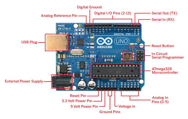
Arduino Uno
DataSheet
Processor: ATmega328P (8-bit, 16MHz)
Flash Memory: 32 KB
SRAM (RAM): 2 KB
GPIO Pins: 14 Digital, 6 Analog
Operating Voltage: 5V
Interface Support: SPI, I2C, UART
Main Use: Sensor interfacing, basic control tasks, 5V logic devices
Pin Out
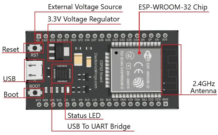
ESP32 Dev Module (ESP32-WROOM-32)
Data Sheet
Processor: Xtensa Dual-Core (32-bit, 240MHz)
Flash Memory: 4MB
SRAM (RAM): 512 KB
GPIO Pins: 34+ (Multifunctional)
Operating Voltage: 3.3V
Interface Support: SPI, I2C, UART, WiFi, Bluetooth
Main Use: IoT applications, wireless communication, high-performance processing
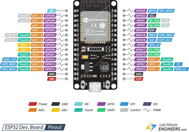
Pin Out: (Include Pinout Diagram or Details)
Here is a comparison sheet of the Arduino Uno and ESP32 microcontrollers:
| Feature |
Arduino Uno |
ESP32 Dev Module (ESP32-WROOM-32) |
| Processor |
ATmega328P (8-bit, 16MHz) |
Xtensa Dual-Core LX6 (32-bit, up to 240MHz) |
| Flash Memory |
32 KB |
4MB (external SPI flash) |
| SRAM (RAM) |
2 KB |
520 KB internal SRAM |
| GPIO Pins |
14 Digital, 6 Analog |
34+ GPIOs, multifunctional with input/output capabilities |
| WiFi / Bluetooth |
❌ No |
✅ Yes (WiFi 802.11 b/g/n, Bluetooth v4.2 BR/EDR and BLE) |
| Operating Voltage |
5V |
3.3V |
| Power Consumption |
High (No Low Power Mode) |
Low Power Modes: Light Sleep, Deep Sleep |
| SPI / I2C / UART |
Yes (Limited ports) |
Yes (Multiple SPI, I2C, UART interfaces) |
| Advanced Features |
No |
✅ Touch sensor, PWM, DAC, ADC (12-bit), Hall sensor, Temperature sensor, IoT support |
Program Development & Simulation (Arduino Uno)
The Arduino Uno is a widely used microcontroller board for embedded system automation, based on the ATmega328P. It operates at 5V and can be powered via USB or an external 7–12V power supply. Key features include a 16 MHz crystal oscillator, 6 analog inputs, and 14 digital input/output pins (6 of which support PWM). It is programmed using the Arduino IDE in C/C++.
Embedded Programming with Arduino
I wrote and uploaded the code using the Arduino IDE, which provides a user-friendly programming interface for microcontrollers.
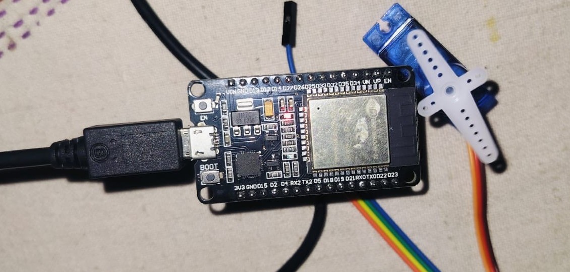
Components and Sensors Used
I worked with four different components and sensors: RGB LED, servo motor, ultrasonic sensor, and LED. Implementing these projects helped me develop a deeper understanding of various aspects of Arduino programming.
Step-by-Step Guide
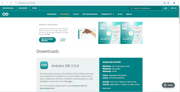 Step 1: Download Arduino IDE from the official website. |
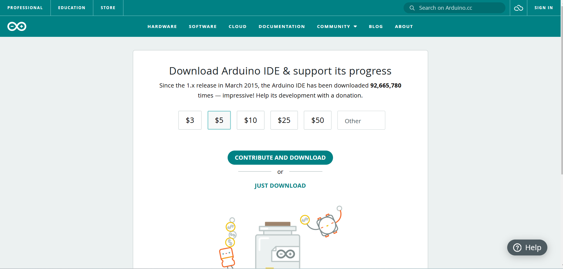 Step 2: Click "Just Download" to proceed without donating. |
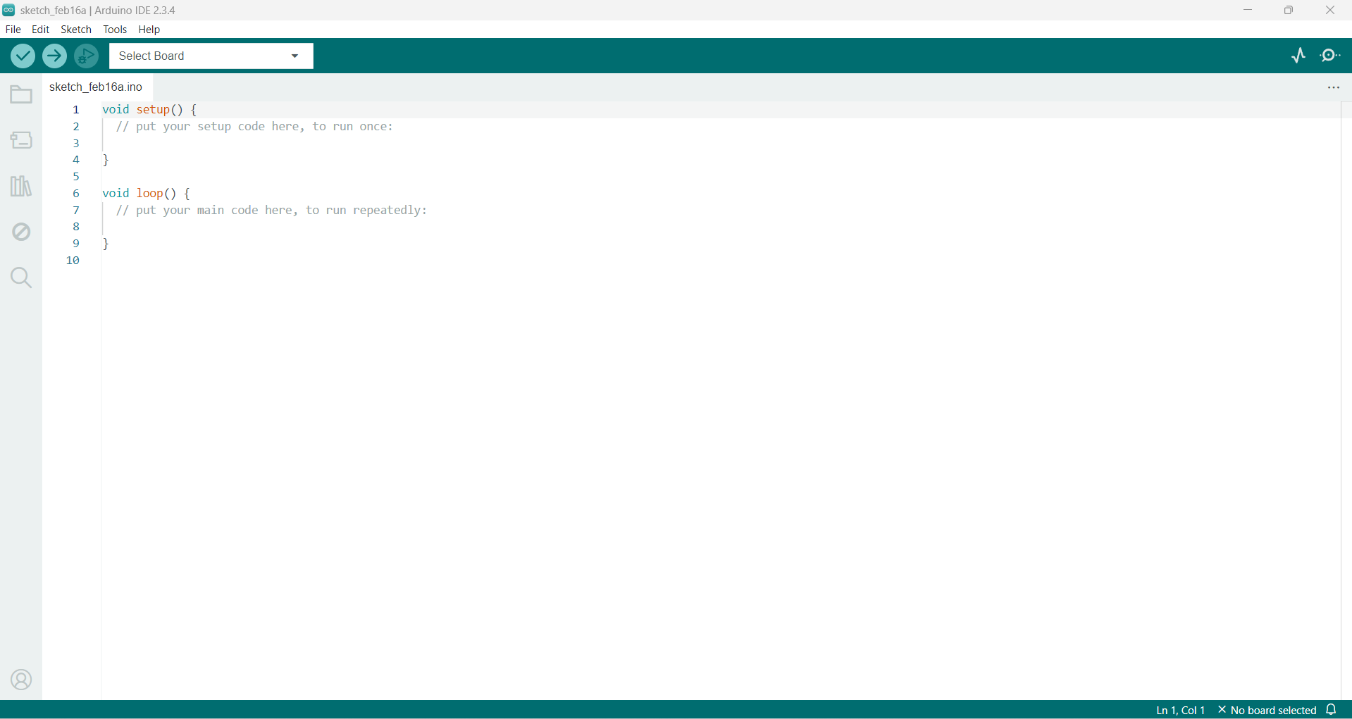 Step 3: Open Arduino IDE, where the default sketch appears.
|
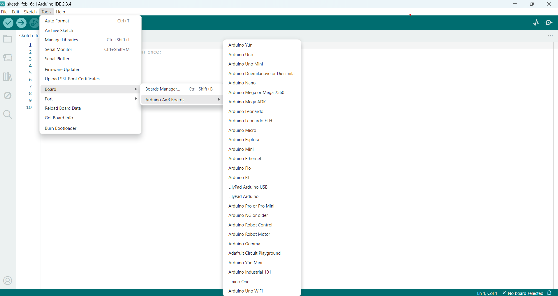 Step 4: Select your board from Tools > Board menu. |
 |
 |
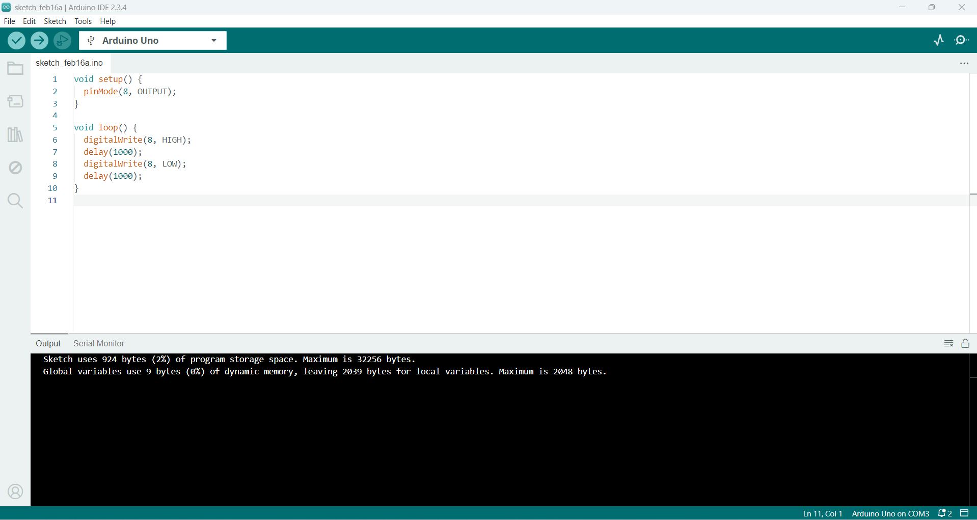
LED Blinking
I learned how to define pins and set their outputs for LED blinking.
I turned LEDs on and off to understand the basics of digital output.
| |
 |
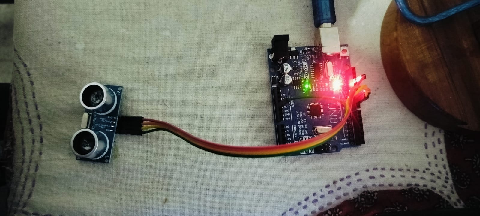 |
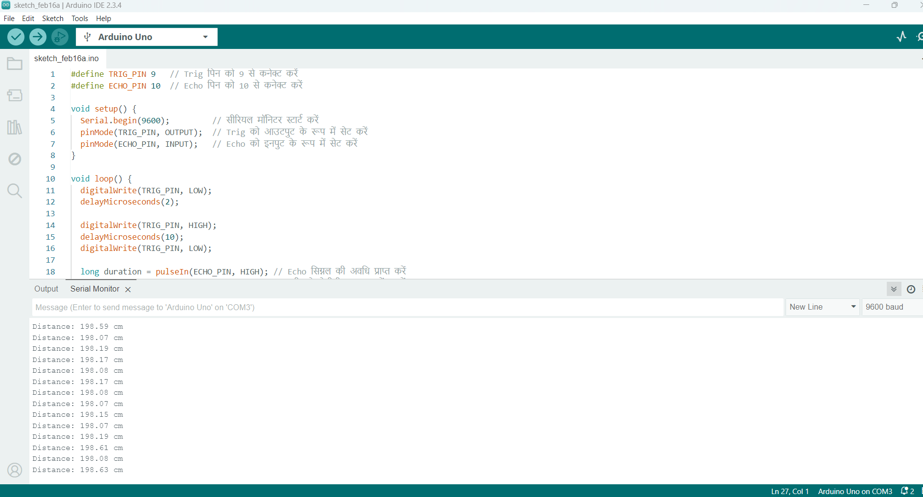
2. Ultrasonic Sensor
Gained knowledge of input and output pin operations.
learned how to broadcast and receive echo signals using the sensor.
Used the pulseIn() method to calculate distance and time duration.
|
|
 |
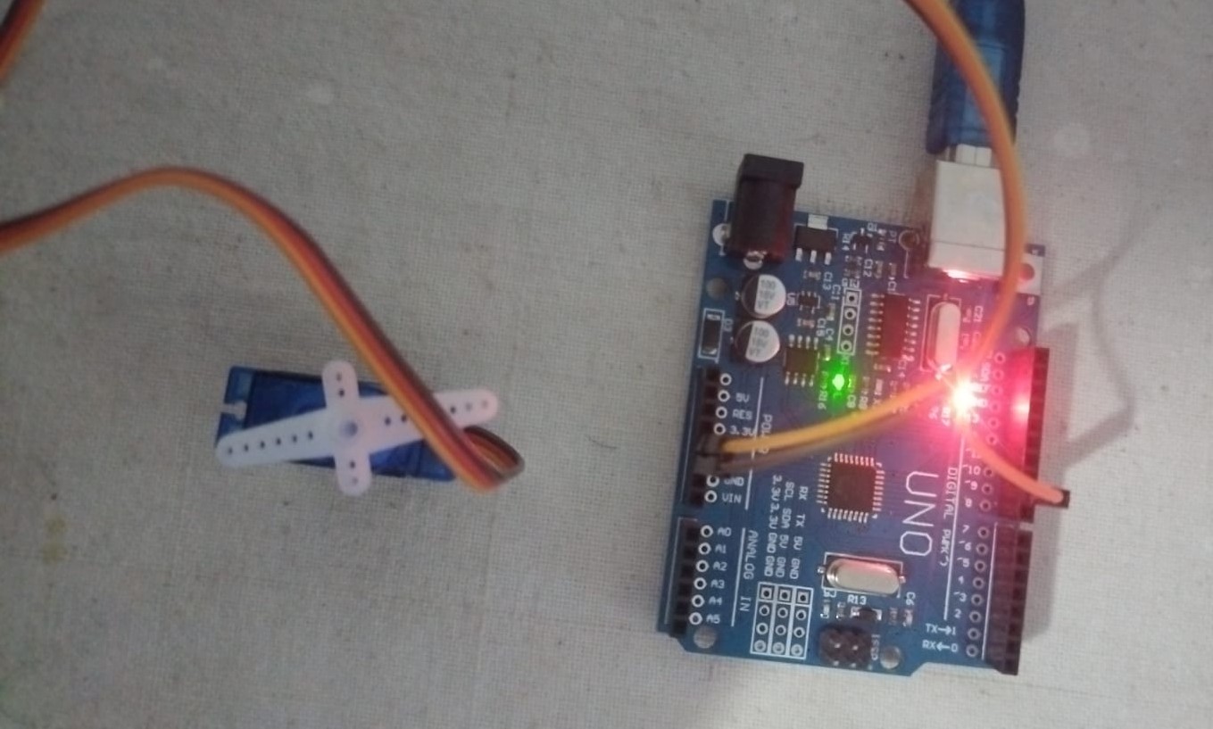 |
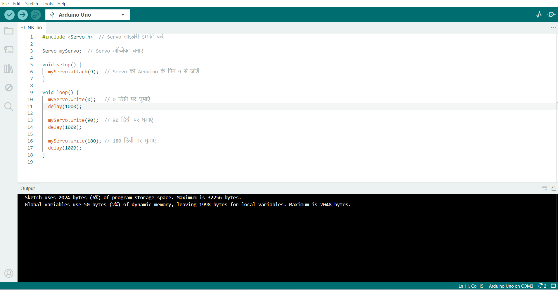
| 3. Servo Motor
A servo motor learned how to use a servo motor to control motor angles.
Gained the ability to rotate smoothly for precise motor control.
|
|
 |
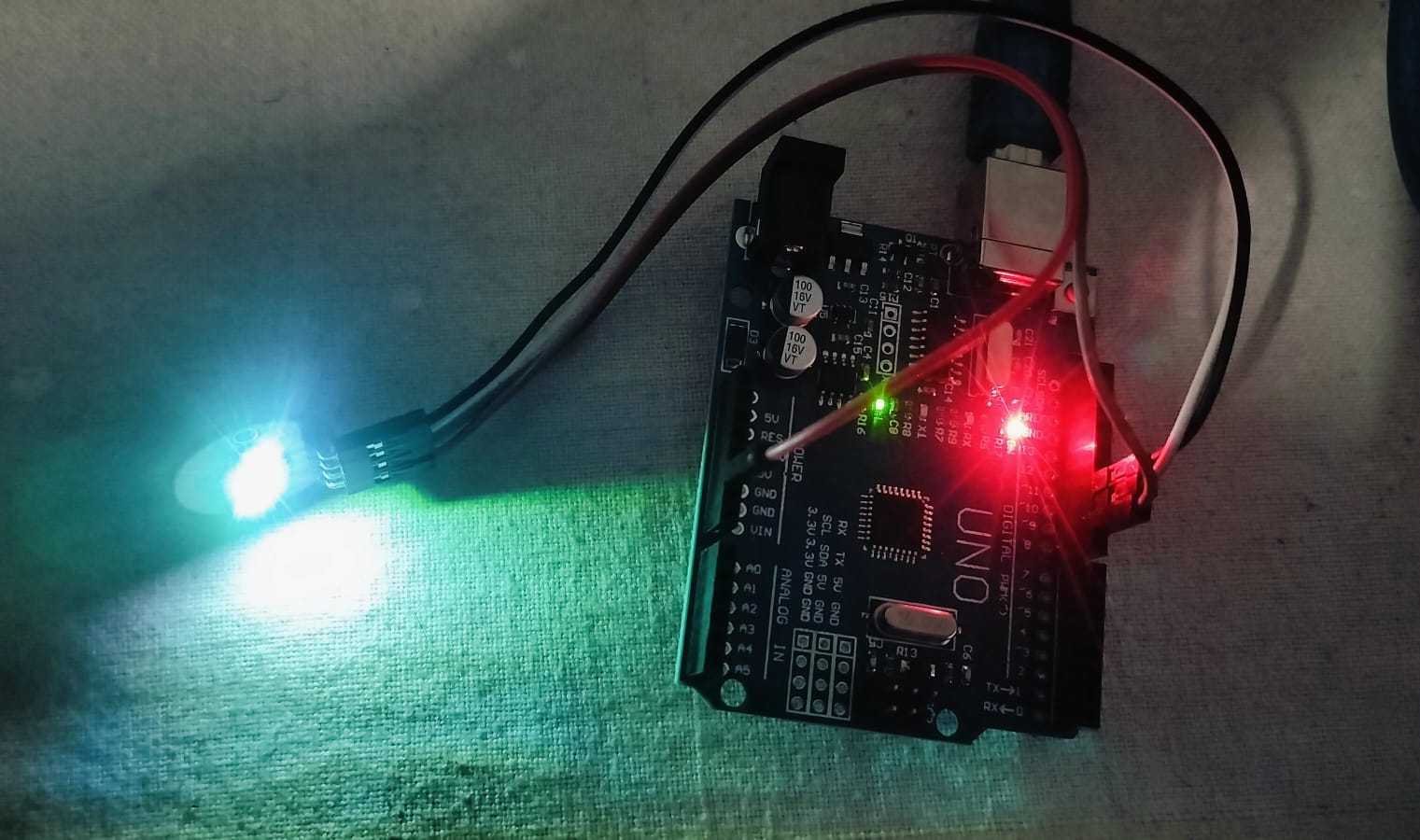 |
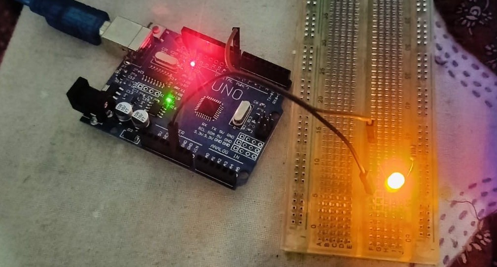
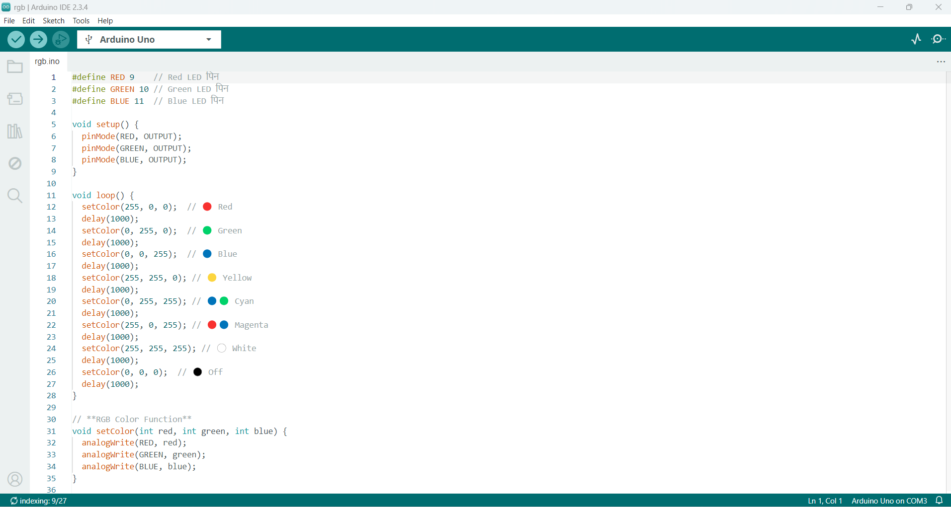
4. RGB LED
Learned how to control multiple LEDs within a single sensor.
Discovered how to use programming logic to mix colors and create visual effects.
|
|
I also learnt how to use program files, add libraries, and configure programming in the Arduino IDE with all of these projects. My knowledge of the Arduino platform and the useful applications of these components in actual projects has significantly increased as a result of this assignment.
Program Development & Simulation (ESP32)
The MicroPython Another programming language made especially to operate on microcontrollers and embedded systems is called Python. Simple communication with sensors and other components is made possible by this.. MicroPython has built-in libraries for controlling hardware, including GPIO, I2C, SPI, and PWM, and it offers an interactive mode through the REPL (Read-Eval-Print Loop). Its mobility and simplicity make it perfect for quick prototyping and teaching. When combined with devices like the ESP32, which has built-in Bluetooth and Wi-Fi,
Exploring Embedded Programming with MicroPython on ESP32
Development Environment
I wrote, compiled, and uploaded code using Thonny. This software provides a user-friendly microcontroller programming interface.
Sensors and Components Used
I worked with four sensors and parts: RGB LED, servo motor, ultrasonic sensor, and LED. I developed a thorough understanding of many facets of Arduino programming by putting these projects into practice.
Step-by-Step Guide
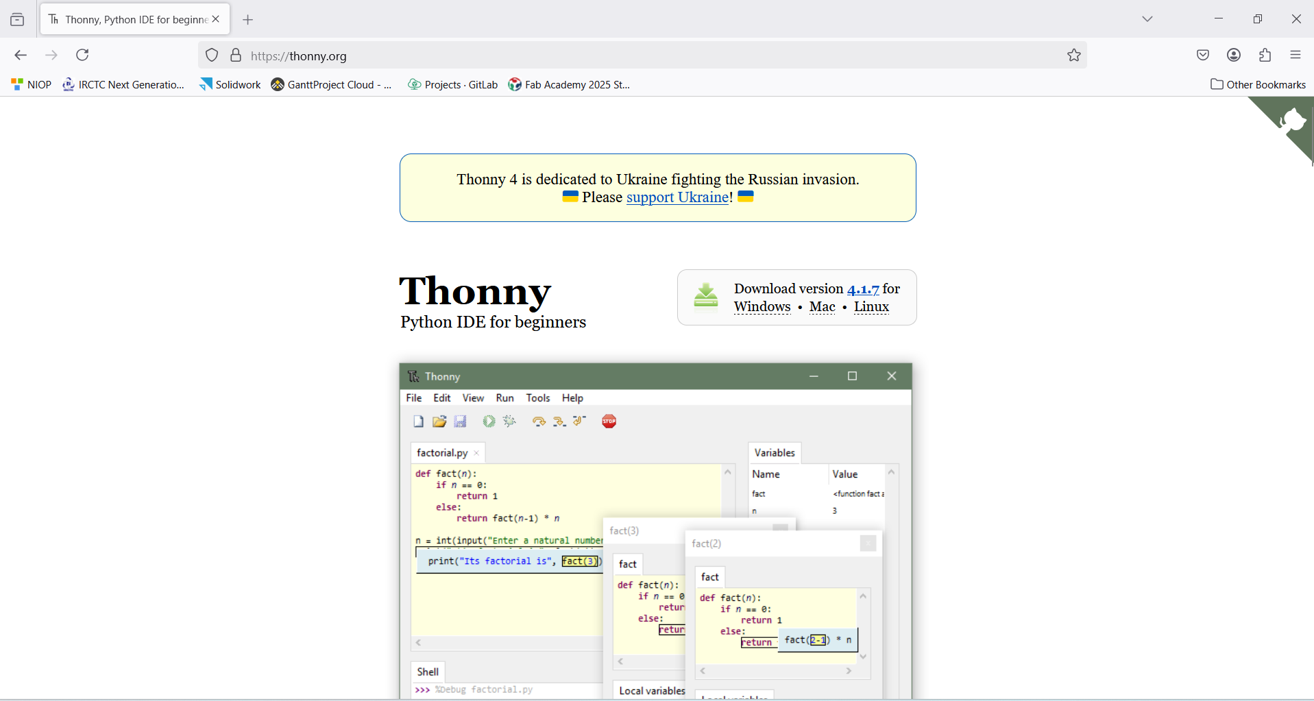
Downloading Thonny IDE:
This screenshot shows the official Thonny.org website, where you can download the Thonny IDE suitable for your operating system (Windows, Mac, Linux).
|
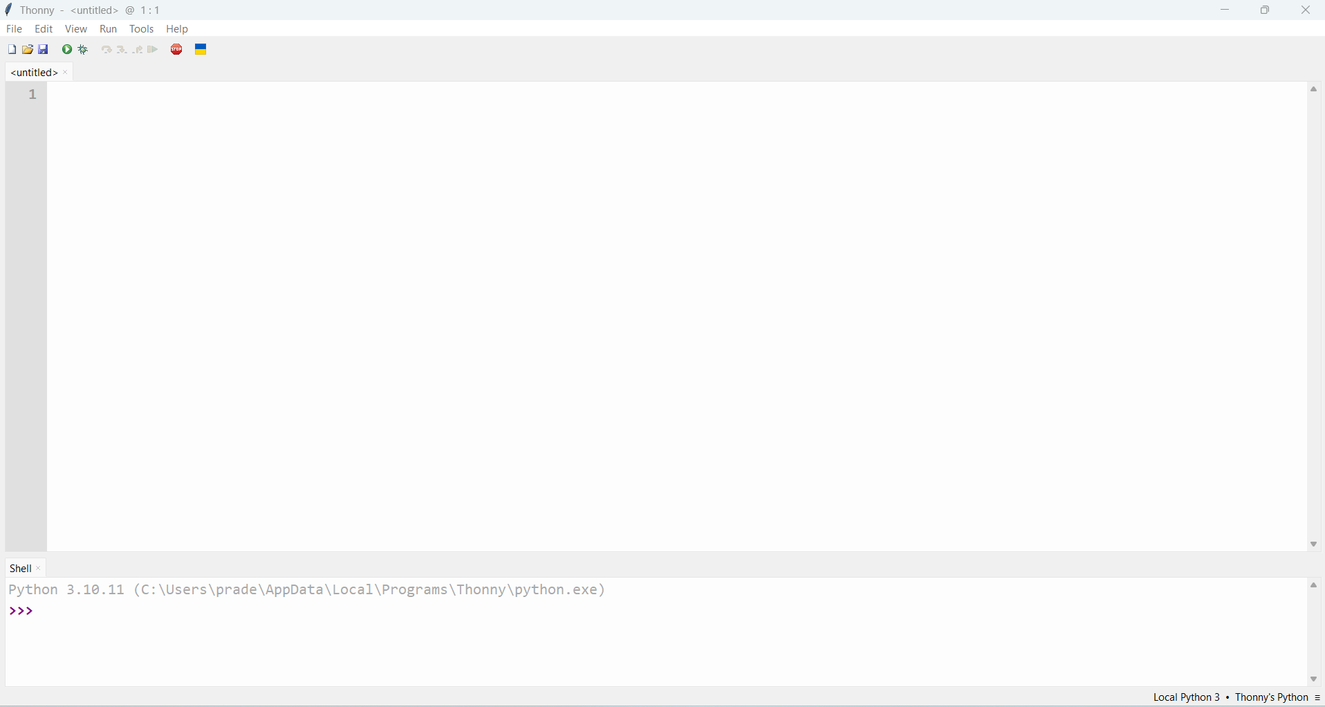
Launching Thonny IDE:
Thonny opens with a clean and simple interface. This screenshot shows the main editor and shell, ready to write Python code.
|
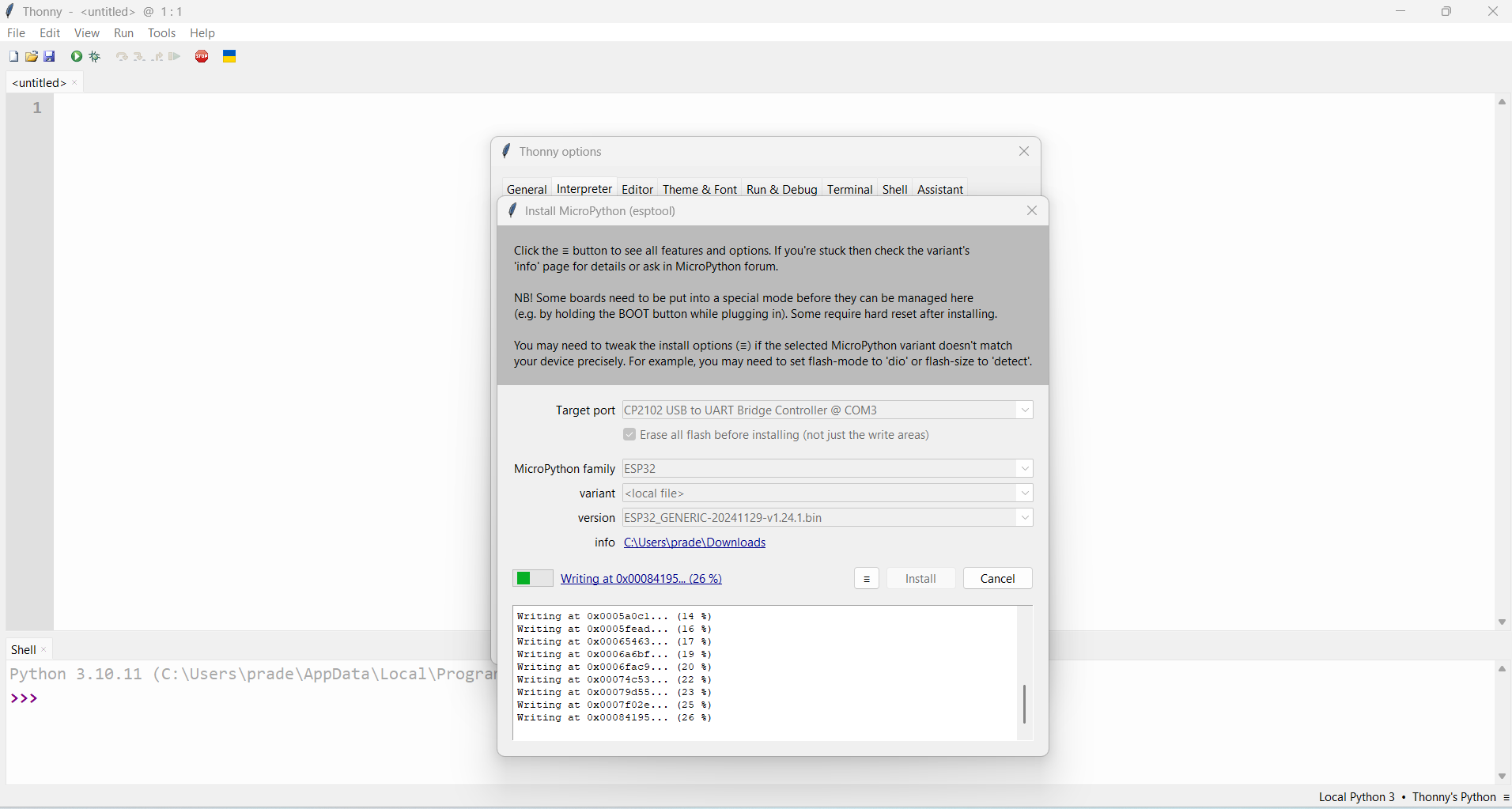
Installing MicroPython (ESP32) Support:
In this image, the Thonny options window is open, where MicroPython firmware is being installed for the ESP32 board. This step is essential to program ESP32 using Thonny.
|
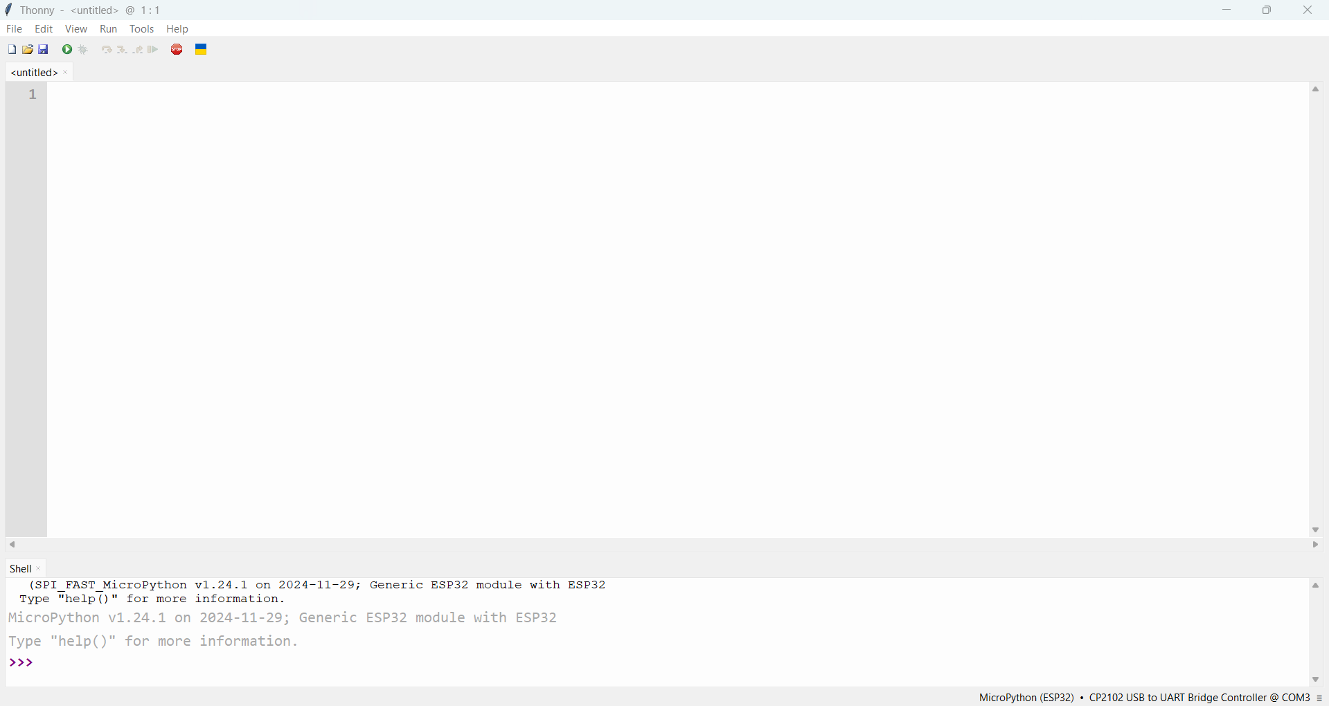
ESP32 Connected and Ready:
This screenshot shows that the ESP32 is successfully connected via COM port and running MicroPython. You can now upload and run code on the board.
|
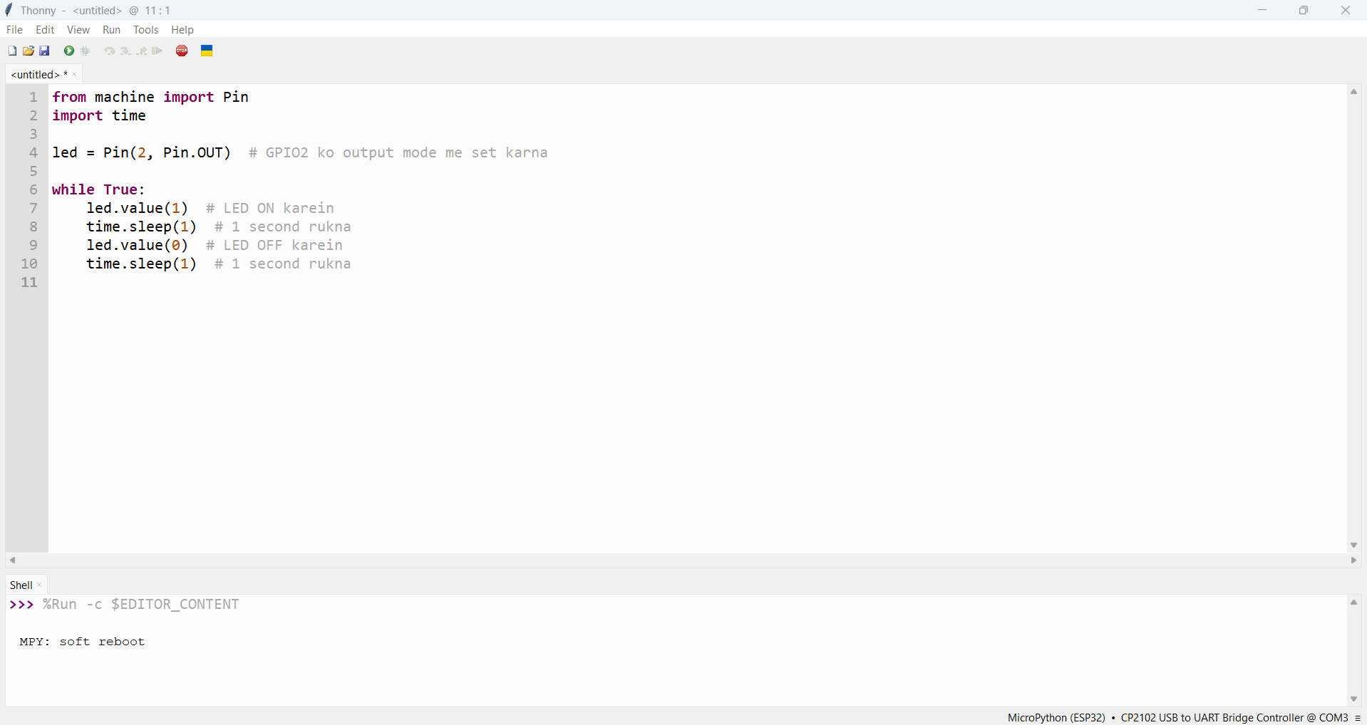
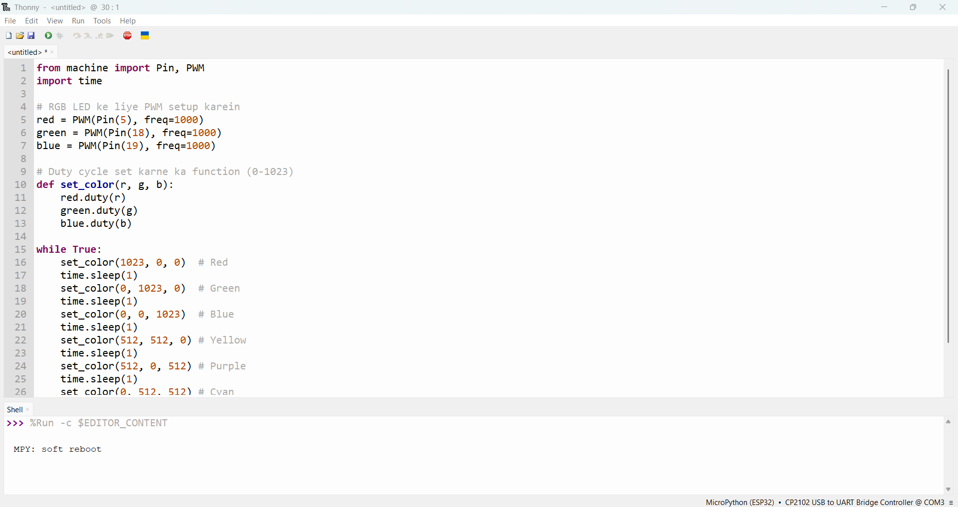
LED Blinking Code:
In this code example, GPIO2 is set as an output pin to blink an LED. The while True loop turns the LED ON and OFF at 1-second intervals using time.sleep(1).
|
|
|
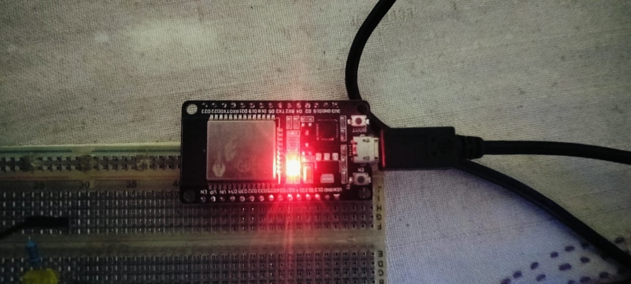
LED Blinking:
I gained knowledge about defining pins and setting them as outputs. I learned how to use MicroPython to interact with simple digital outputs by turning the LED on and off.
|
|
 |
 |
|
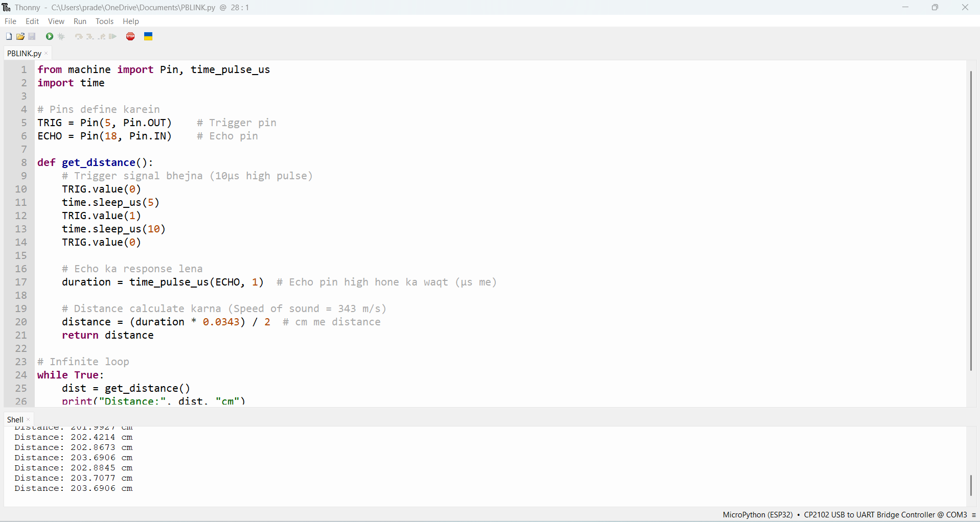
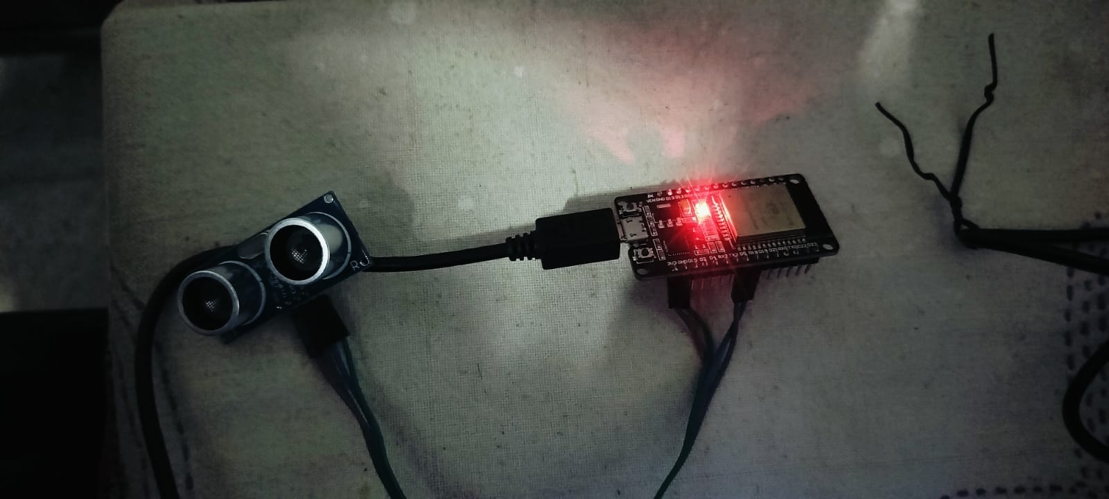
Ultrasonic Sensor:
I learned how to use the ultrasonic sensor's input and output pins, how to send and receive an echo from it, and how to use the pulse time to determine distance. Additionally, I learned how to measure the time period of the sensor's echo using the pulse_time() method.
|
|
 |
 |
|
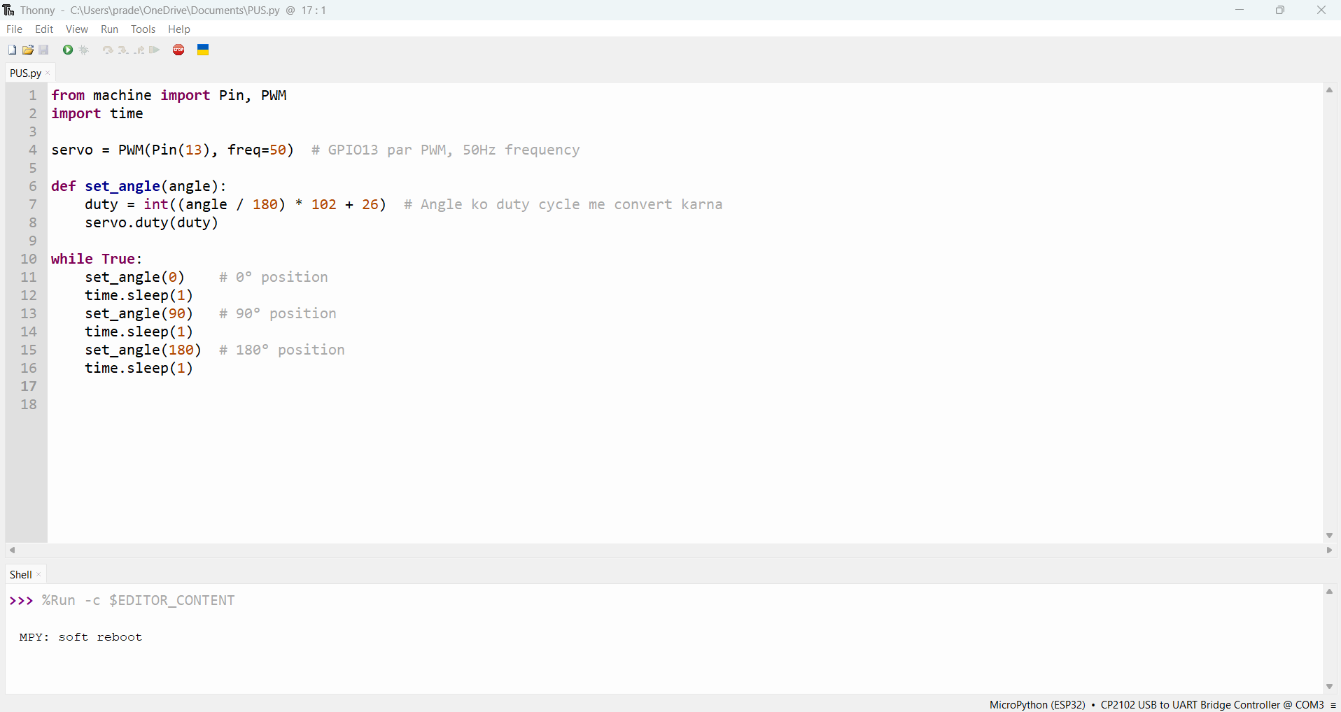
Servo Motor:
Through the servo motor project, I learned how to control the motor by adjusting its angle and using the library to adjust its position. I learned how to quickly regulate motor rotation and became familiar with the MicroPython servo library.
|
|
 |
 |
|
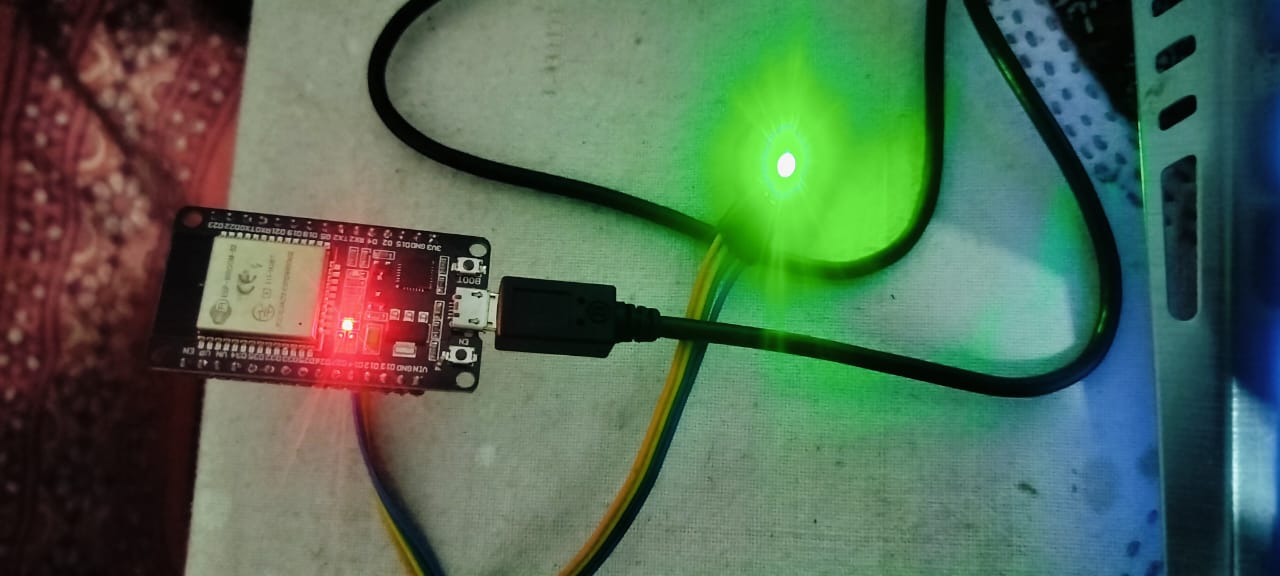
RGB LED:
Working with RGB LEDs taught me how to define the pins of each color and change their states in order to control many LEDs within a single component.
|
|
I also learned how to use program files, add libraries, and build up a MicroPython programming environment through all of these tasks. I now have a much better understanding of MicroPython programming on the ESP32 thanks to this assignment.
Servo Motor Simulation in Tinkercad
Users can design and model electronic circuits using the online simulation program TinkerCAD. It offers a straightforward and user-friendly interface for building circuits using a variety of parts, including as motors, sensors, LEDs, and microcontrollers. TinkerCAD features drag-and-drop capability, making it easier for users to construct and test circuits in a virtual environment, so enabling testing and debugging of projects before implementing them with physical hardware. TinkerCAD offers a hands-on learning experience in electronics and circuit design, which is particularly helpful for novices.
 I ahve to sarch in Sarch engisan Ardiono IDF |
 Clik on the just dwonlodr |
 opne the Aridno Sftwerew
|  i have to slackt the bord and do and some seting of the bord inthe toolsd |
1. Create an account or sign in
1. First, visit the Tinkercad website and register or log in.
Use your Google account or email address to create an account.
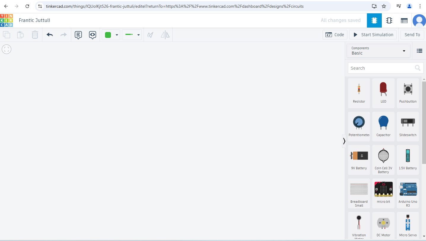
2. Begin a fresh endeavor,
Click the "Create new design" option on your dashboard after logging in. This will create a fresh workspace for you to begin circuit design and simulation.
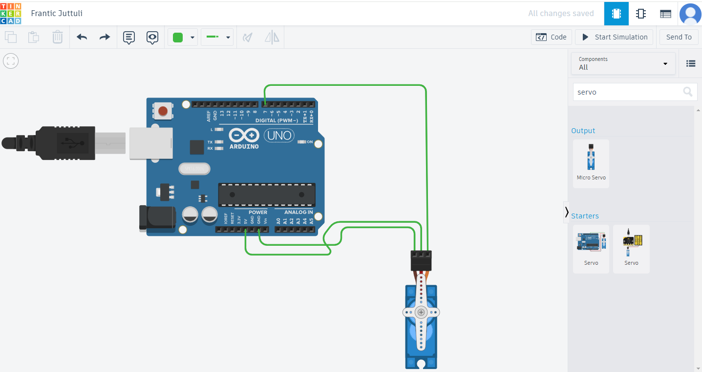
4. The servo motor is added
Find "servo motor" under the "Components" menu, then drag it to the workspace. The workspace will display the servo motor. Typically, it contains three pins: signal (PWM), ground (GND), and power (VCC).
5. Attach the Arduino to the servo motor.
Drag the Arduino Uno board from the Components tab onto the workspace..
Attach the servo motor's VCC pin to the Arduino's 5V pin.
Connect the GND pin of the servo motor to the GND pin of the Arduino.
A PWM-capable Arduino pin, like pin 9, is connected to the servo motor's signal pin.
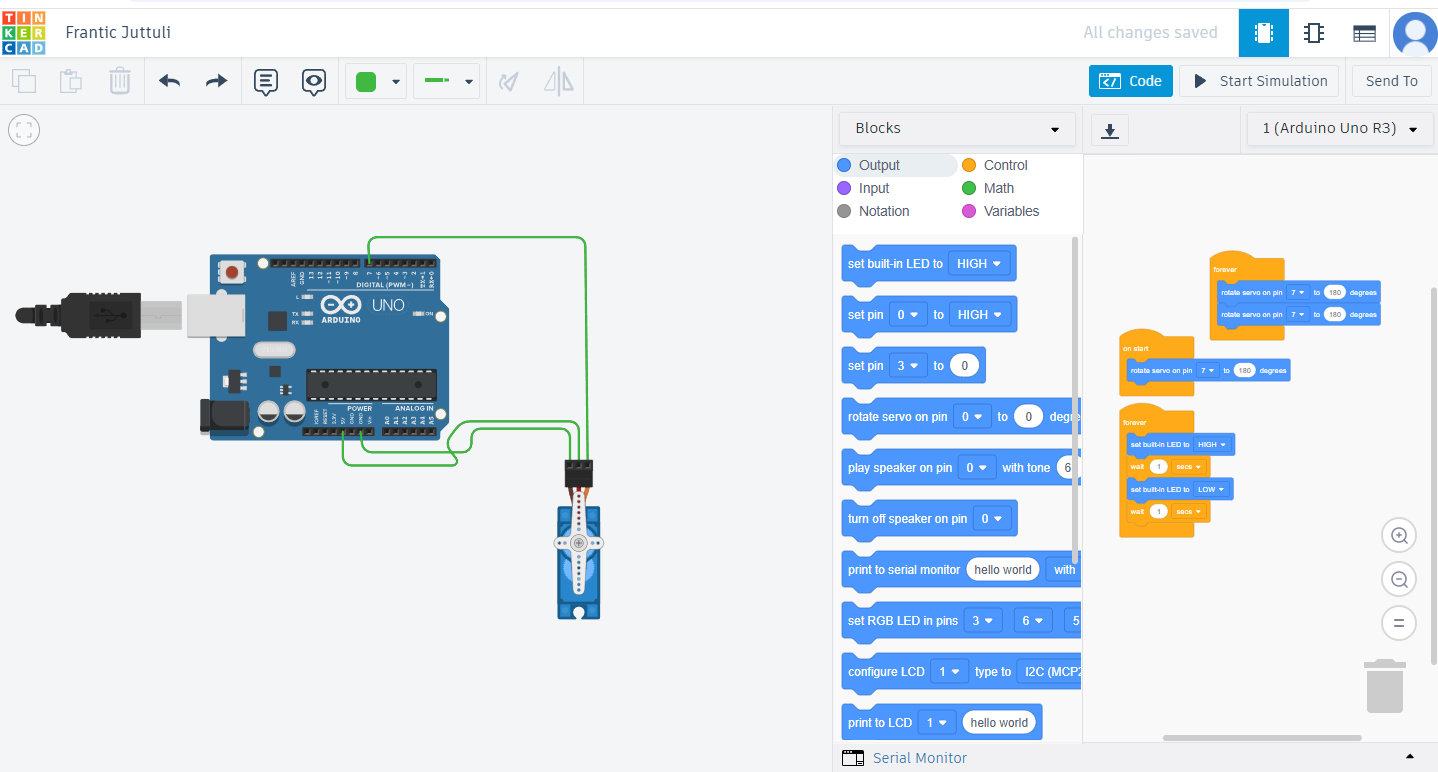
6. Test, Debug, and Simulate
After adjusting the perpetual block and adjusting the servo motor's degree from 90 to 180, I ran the simulation. At last, we place the block within the block.. Additionally, the motor began to move automatically after the simulation was finished.
Tools I Used for This Assignment
- Microcontrollers:Arduino Uno , ESP32
- Software & IDEs:
- Simulation Tools: Tinkercad (for Arduino Uno)
- Programming Languages:
- Components Used:
Concept by me structured by ChatGPT.
Original File is Here